


WR8
6 720 607 884 (2009/05) GB
WR8..P...
WR11..P...
With piezo ignition and double safety system
consisting of flue gas monitor and heat
exchanger temperature sensor.
Safety instructions:
If you smell gas:
- Do not operate any electrical switches.
- Do not telephone from inside the danger area.
- Turn off the gas cock.
- Open windows and ventilate room.
- From outside, call the gas company and your approved
installer.
Do not use or store easily combustible materials in the vicinity
of the appliance.
Gas Instantaneous Water Heater
Installation Manual and Operating Instructions
Installation and servicing of the appliance may only be
carried out by an approved technician.
The appliance should be regularly serviced in order to ensure
that it remains in perfect and safe working order.
If there is a risk of freezing, the appliance must be switched
off and drained. If the appliance has not been drained during
a cold spell, when it is switched on again check that it
produces hot water. If problems occur, contact your installer
2 6 720 607 884
2.5 Gas connection ................................................................. 5
2.6 Flue....................................................................................... 6
2.7 Commissioning .................................................................. 6
3. Operation and maintenance
3.1 Function .............................................................................. 7
3.2 Water temperature control.............................................. 7
3.3 Appliance adjustments .....................................................7
3.4 Maintenance ...................................................................... 7
3.5 Purge the appliance ......................................................... 7
3.6 Flue gas safety device ..................................................... 7
3.7 Converting to a different gas type ................................8
3.8 Troubleshooting ................................................................. 8
4. Operation ............................................................................... 12
1. Technical Characteristics and Dimensions
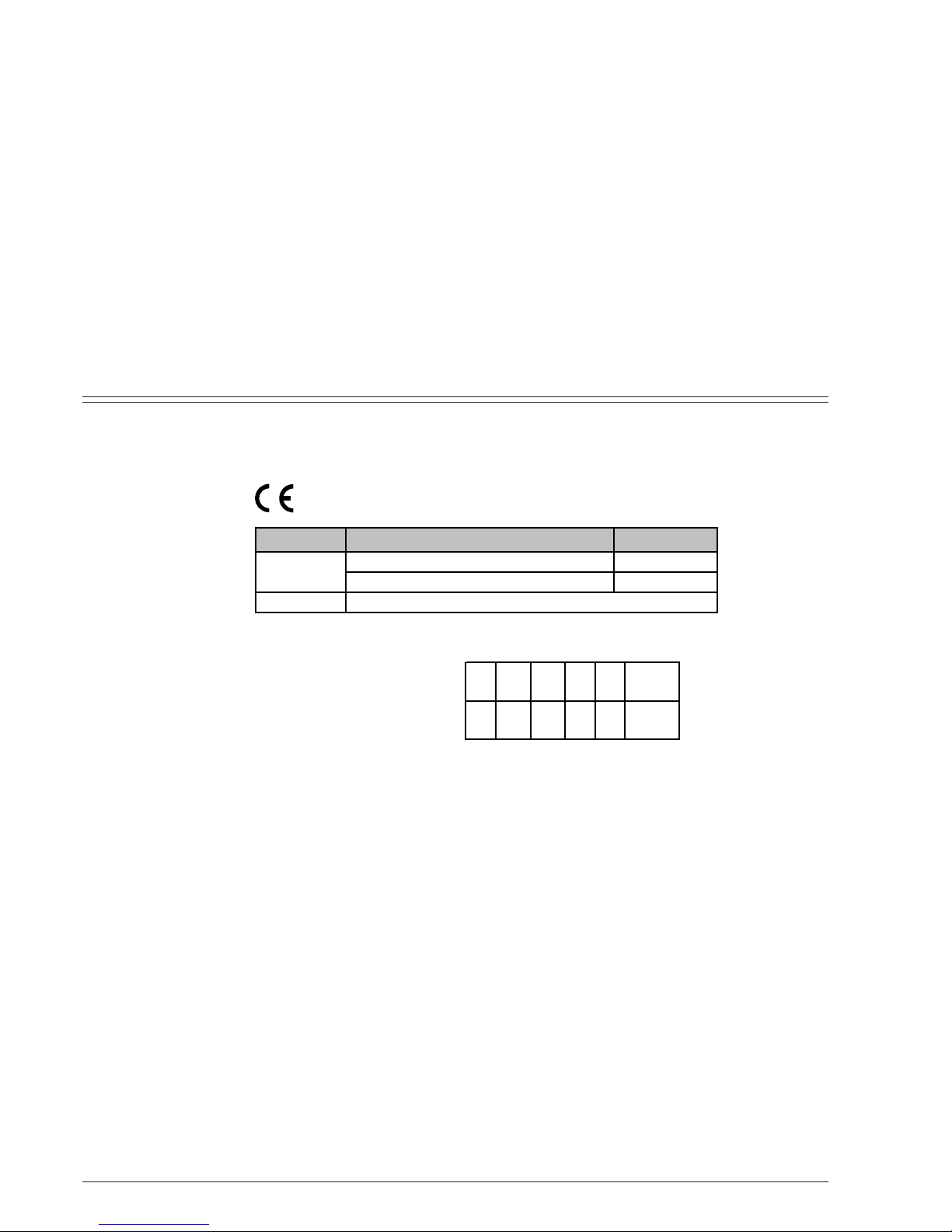
1.1 Category, Appliance Type and Approval Number
1.2 General Description
This water heater is fitted with a piezo system.
Guaranteed safety provided by:
- Gas-tight ionisation detector that prevents escape of gas
if there is no flame.
- Flue gas safety device that switches off the appliance if
the flue is not functioning properly.
- Temperature limiter which protects the heat exchanger
against overheating.
Heat exchanger has no tin/lead lining.
Automatic water valve made of glass-fibre reinforced
polyamide, 100% recyclable.
Automatic control of water flow maintains constant flow rate
even with fluctuating supply pressure.
Proportional adjustment of gas and water flow rates in order
to ensure an even temperature gradient.
Gas valve with adjustable output via a slide control.
1.3 Explanation of Model Code
Contents
W Gas instantaneous water heater
R Proportional output control
8 Flow rate (l/min)
P Piezo ignition
31 LPG (butane/propane)
S... Country code
1. Technical Characteristics and Dimensions
1.1 Category, Appliance Type and Approval Number ...... 2
1.2 General Description ......................................................... 2
1.3 Explanation of Model Code ............................................ 2
1.4 Dimensions ......................................................................... 3
1.5 Appliance design ............................................................... 3
1.6 Technical characteristics................................................. 4
2. Preconditions for installation
2.1 Regulations .........................................................................5
2.2 Location .............................................................................. 5
2.3 Fixing the appliance .......................................................... 5
2.4 Water connection ............................................................. 5
0464 BQ 20
W R 8 P 31 S…
W R 11 P 31 S…
MODEL COUNTRY CATEGORY
BE, CH, ES, FR, GB, IT, PT, LU, HR
I
3+
NL, DE
I3B/P
TYPE
WR8/11 P…
B
11BS

36 720 607 884
1.4 Dimensions
Fig. 2
1.5 Appliance design
Fig. 3
1. Heat exchanger
2. Main burner
3. Injector
4. Slow ignition valve
5. Temperature control
6. Venturi
7. Adjusting screw for min. water flow rate
8. Water valve
9. Water throttle
10. Water filter
11. Membrane
12. Cold water pipe
13. Magnetic unit
14. Gas supply pipe
15. Gas filter
16. Regulating screw
17. Pilot filter
18. Piezo
19. Hot water pipe
20. Output control
21. Igniter button
22. Main gas valve
23. Gas valve for pilot burner
24. Pilot burner injector
25. Gas valve
26a. Testing point for supply pressure
26b. Testing point for burner pressure
27. Thermocouple
28. Igniter electrode
29. Temperature limiter
30. Flue gas safety device
1. Front cover
2. Hole for fixing to wall
3. Observation window
4. Temperature control
5. Output control
6. Gas connection
7. Exhaust pipe union
8. Draught diverter with flue
gas monitor
9. Heat exchanger
10. Automatic gas valve
11. Piezo
12. Water valve
Dimensions
A B C D E F G H (Ø)
(mm)
WR8..P...
WR11..P...
LPG
580310 3/4"60463112,5228 25

4 6 720 607 884
1.6 Technical characteristics
* Hi 15°C - 1013 mbar - dry : LPG: Butane 45.7 MJ/kg (12.7 kWh/kg) Propane 46.4 MJ/kg (12.9 kWh/kg)
** This figure must not be exceeded taking account of water expansion
*** At maximum rated heat output
Technical Data Symbol Unit WR8 WR11
Rated max. heat output
P
n
kW 11.8 19.2
Rated min. heat output
P
min
kW 7.0 7.0
Output (modulation range)
kW 7.0 - 11.8 7.0 - 19.2
Rated max. heat input
Q
n
kW 13.5 21.8
Rated min. heat input
Q
min
kW 8.1 8.1
Supply pressure
LPG (butane/propane)
G30/G31
mbar
28-30/37 28-30/37
Consumption
LPG (butane/propane)
G30/G31 kg/h 1 1.6
Number of injectors
12 12
Max. water pressure**
p
w
bar 12 12
Temperature control at maximum setting
Temperature increase
°C 50 50
Flow rate
l/min 3.5 5.5
Min. operating pressure
p
wmin
bar 0.1 0.1
Temperature control at minimum setting
Temperature increase
°C 25 25
Flow rate
l/min 7 11
Min. operating pressure
bar 1 1
Draught requirement
mbar 0.015 0.015
Flow rate
g/s 13 13
Temperature
°C 170 170
Output and heat
demand
Gas supply
specifications *
Flue
specifications***
Water system specifications
 Loading...