


Worcester 14/19CBI
Bosch Worcester 14/19CBI, 19/24CBI, Worcester 9/14CBI, Worcester 19/24CBI Installation And Servicing Instructions
9/14CBi, 14/19CBi, 19/24CBi
WALL MOUNTED BOILERS FOR CENTRAL HEATING
AND INDIRECT SUPPLY OF DOMESTIC HOT WATER
INSTALLATION AND
SERVICING INSTRUCTIONS
This appliance is for use with Natural Gas or LPG (Cat II 2H3P).
9/14CBi GC NUMBER 41 311 50 (N.G.) 9/14CBi GC NUMBER 41 311 51 (LPG)
14/19CBi GC NUMBER 41 311 52 (N.G.) 14/19CBi GC NUMBER 41 311 53 (LPG)
19/24CBi GC NUMBER 41 311 54 (N.G.) 19/24CBi GC NUMBER 41 311 55 (LPG)
APPLIANCE OUTPUTS
IMPORTANT: THESE INSTRUCTIONS APPLY IN THE UK ONLY
AND MUST BE LEFT WITH THE USER OR AT THE GAS METER
Read the instructions before starting work - they have been written to make
the installation easier and prevent hold-ups.
9/14CBi N.G.
Minimum 9.0 kW
Maximum 14.0 kW
9/14CBi LPG
Minimum 10.0 kW
Maximum 14.0 kW
14/19CBi N.G.
Minimum 14.0 kW
Maximum 19.1 kW
14/19CBi LPG
Minimum 14.0 kW
Maximum 19.1 kW
19/24CBi N.G.
Minimum 19.1 kW
Maximum 23.5 kW
19/24CBi LPG
Minimum 19.1 kW
Maximum 23.5 kW
Worcester supports the
Benchmark code of practice

1.1 Gas Safety (Installation & Use) Regulations 1998.
It is the law that all gas appliances are installed by a competent
person in accordance with the above regulations. Failure to
install appliances correctly could lead to prosecution. It is in
your interest, and that of safety, to ensure compliance with the
law.
1.2 The manufacturers notes must not be taken, in any way, as
overriding statutory obligations.
1.3 The compliance with a British Standard or European Norm
does not, in itself, confer immunity from legal obligations.
1.4 The installation of the appliance must be in accordance with
the relevant requirements of the Gas Safety Regulations, current
IEE Regulations, Building Regulations, Building Standards
(Scotland) and local water bye-laws.
1.5 The installation should follow the recommendations of the
following British Standards unless otherwise indicated and to
any other relevant standards.
BS5440:1 - Flues and ventilation for gas appliances: Flues
BS5440:2 - Flues and ventilation for gas appliances: Air supply.
BS5449 - Central heating for domestic premises.
BS5546:1 - Installation of gas hot water supplies.
BS5482 - Domestic Propane Gas Burning Installations.
BS6700 - Domestic water supply (when relevant).
BS6798 - Installation of gas fired hot water boilers.
BS6891 - Low pressure gas pipework installations up to 28mm
(R1).
BS7593 - Water treatment.
1.6 The appliance and/or components must conform, where
applicable, to all relevant Directives.
1.7 In accordance with COSSH the appliance does not contain
any substances which are harmful to health.
1.8 Product Liability regulations indicate that, in certain
circumstances, the installer can be held responsible, not only for
mistakes on his part but also for damage resulting from the use
of faulty materials. We advise that to avoid any risk, only
quality approved branded fittings are used.
1.9 These instructions cover, as far as possible, the foreseeable
situations which may arise. Contact The Worcester Technical
Department, Telephone: 08705 266241, for advice on specific
installations.
1.10 The appliance shall not be installed into a room or internal
space below ground level when it is intended for use with LPGpropane (G31). This does not preclude the installation into a
room or space which are basements with respect to one side of
the building but are open to the ground on the opposite side.
The Benchmark initiative is the new code of practice to
encourage the correct installation, commissioning and servicing
of domestic central heating boilers and system equipment.
The ‘checklist’ is a vital document that must be completed by
the installer at the time of installation and handed to the
householder. It confirms that the boiler has been installed and
commissioned according to the manufacturers instructions.
Without the completion of the checklist, manufacturers may refuse
to respond to a call-out from a householder, who will be advised
that he or she must call back the installer, who has not fulfilled his
obligations to record the information required by the initiative.
2.1 General Information
The Worcester boilers provide a heat output of between 9-14kW
(9/14CBi), 14-19kW (14/19CBi) & 19-24kW (19/24 CBi) factory set at
mid-range and contain a temperature control and all the appropriate
safety controls. They are suitable for fully pumped open vent or
sealed systems.
They can be connected to a domestic hot water supply system
through an external S or Y plan system.
2.2 Electrical Supply
230V - 50Hz. Load 125 watts. External fuse 5A to BS 1362, Internal
fuse F1 - 4A.
IP Rating: IP 20.
2.3 Gas supply
The 19/24CBi appliance requires a maximum of 2.72 m
3
/h of
natural gas (G20), 1.05 m
3
/h propane (G31).
The 14/19CBi appliance requires a maximum of 2.18 m
3
/h of
natural gas (G20), 0.84 m
3
/h propane (G31).
The 9/14CBi appliance requires a maximum of 1.62 m
3
/h of
natural gas (G20), 0.63 m
3
/h propane (G31).
The installation and the connection of the gas supply to the
appliance must be in accordance with BS6891or BS5482 for LPG.
The meter or regulator should deliver a dynamic pressure of 20
mbar for natural gas (G20) at the appliance, which is equivalent
to about 19.0 mbar at the gas valve inlet pressure test point, or a
dynamic pressure of 37 mbar for propane (G31) - equivalent to
36.0 mbar at gas valve inlet pressure test point.
2.4 Installation
The appliance is suitable for indoor installation only and for use
with a fully pumped open vent or sealed system with an indirect
cylinder. It is not suitable for use with a direct cylinder.
If the appliance is fitted in a cupboard or a compartment is built
around it after installation, then the structure must conform with
the requirements of BS6798. The spaces specified for servicing
must be maintained. Refer to Section 6.
2.5 System
All dirt and system cleanser must be fully flushed from
any system to be connected to the appliance. Refer to Fig. 5,6 and 7.
A system by-pass maybe required dependent on the system which can
take the form of a single uncontrolled radiator located at least 2m from
the boiler - usually in the bathroom. See Section 7 for more details.
The connections in any system must withstand a pressure of up to 3 bar..
Radiator valves must conform to BS2767:10.
2.6 Domestic Hot Water
Single feed direct cylinders are NOT suitable and must not be used.
A HW cylinder must be of the indirect coil type and suitable for
2. Introduction1. Installation Regulations
2
1. Installation Regulations . . . . . . . . . . . . . . . . . . . . . . . . . . Page 2 11. Installing the Appliance . . . . . . . . . . . . . . . . . . . . . . . . . . Page 15
2. Introduction . . . . . . . . . . . . . . . . . . . . . . . . . . . . . . . . . . . . Page 2 12. Commissioning the Appliance . . . . . . . . . . . . . . . . . . . . Page 23
3. Technical Data . . . . . . . . . . . . . . . . . . . . . . . . . . . . . . . . . . Page 4 13. Instructions to the User. . . . . . . . . . . . . . . . . . . . . . . . . . Page 24
4. Siting the Appliance . . . . . . . . . . . . . . . . . . . . . . . . . . . . . Page 6 14. Inspection and Service. . . . . . . . . . . . . . . . . . . . . . . . . . . Page 24
5. Flue Terminal Positions. . . . . . . . . . . . . . . . . . . . . . . . . . . Page 7 15. Replacement of Parts . . . . . . . . . . . . . . . . . . . . . . . . . . . . Page 26
6. Air Supply . . . . . . . . . . . . . . . . . . . . . . . . . . . . . . . . . . . . . . Page 7 16. Conversion Instructions. . . . . . . . . . . . . . . . . . . . . . . . . . Page 32
7. System. . . . . . . . . . . . . . . . . . . . . . . . . . . . . . . . . . . . . . . . . Page 8 17. Component Parts List. . . . . . . . . . . . . . . . . . . . . . . . . . . . Page 33
8. Domestic Hot Water . . . . . . . . . . . . . . . . . . . . . . . . . . . . . Page 8 18. Operational Flow Diagram . . . . . . . . . . . . . . . . . . . . . . . Page 34
9. Gas Supply . . . . . . . . . . . . . . . . . . . . . . . . . . . . . . . . . . . . . Page 10 19. Fault Finding . . . . . . . . . . . . . . . . . . . . . . . . . . . . . . . . . . . Page 35
Contents
10. Electrical. . . . . . . . . . . . . . . . . . . . . . . . . . . . . . . . . . . . . . . Page 10
working at a gauge pressure of at least 0.35bar above the relief
valve setting if on a sealed system.
Where a storage system will not have a vent to atmosphere the
installation must comply with Building Regulations and Water
Company bye-laws. If connecting to an existing system the local
authority should be informed.
2.7 Flue
There are 3 fluing options available.
(i) Rear Only Flue Kit.
(ii)
Multi-Directional Horizontal Flue Kit.
(iii) Vertical Flue Kit
A vertical flue option is also available with flue lengths from
1.1m (without cutting) to a maximum of 3.35m (19/24CBi) or
4.1m (9/14 and 14/19CBi). Optional 45° and 90° bends are
available with this option. NOTE: When using flue bends the flue
length is reduced (see Section11.2.8).
2.8 Controls
A control knob adjusts the boiler temperature, switches the
boiler ON or to STANDBY and acts as a lock-out reset.
2.9 Safety
The appliance must not be operated with the inner casing cover removed.
The gas and electricity supplies must be turned off before
servicing or working on the appliance.
The casing is earthed through a push-on connector at the base.
When the casing is refitted this connection MUST be remade.
3
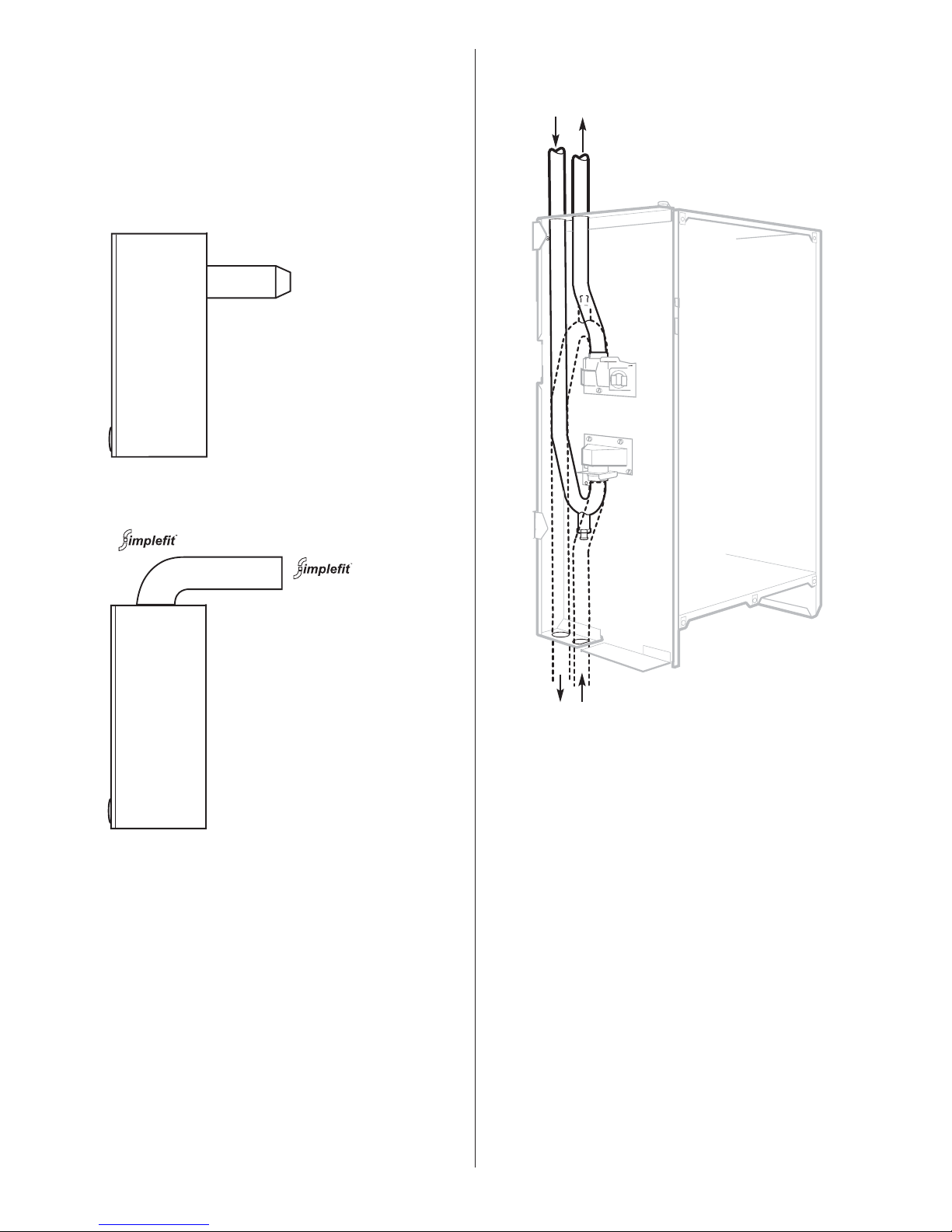
Fig. 1. Water flow diagram.
Pipes
Return Flow
Alternative position
of Flow and Return pipes
NOTE: Flow pipe is at the rear
in the alternative position.
2.10 Operation
Central Heating
A demand for heat will ignite the burner. The temperature is
controlled by the integral sensor. At the end of the demand the
burner will go out and the pump will continue to run for up to 4
minutes and the fan for 1 minute to dissipate the residual heat.
Domestic Hot Water:
The supply of domestic hot water depends upon the type of hot
water equipment installed and the control system.
The use of unvented cylinders must be in accordance with the
manufacturers instructions and relevant to British Standards.
The boiler is despatched from the factory with the flow and
return pipework prepared for top outlet connection.
The pipework can be orientated to allow connection from the
bottom by simply unplugging the bayonet style pushfit connections.
NOTE: When changing from a top connection to one at the bottom the pipe functions are reversed.
Top flow pipe becomes the bottom return pipe.
Top return pipe becomes the bottom flow pipe.
The drain off point on the return pipe becomes an air vent if the
pipes are reversed. In this case a drain point should be fitted
close to the appliance.
Flue can be fitted within
the height of the casing from
220mm to 375mm without
cutting.
The minimum length is
100mm with cutting.
No flue bends or extensions
can be fitted to this system.
Side view
Side view
Flow Return
Standard Flue Kit
can be adjusted from
425mm to 725mm without
cutting.
The minimum length is 250
mm with cutting.
Extended flue lengths upto
a maximum of 2.5m
(19/24CBi) and 3.0m (9/14
and 14/19CBi) are available.
Optional 45° and 90° flue
bend kits are available
NOTE: When using flue
bends the maximum flue
length is reduced (see
Section 11.2.8).
If access to the flue is a
problem then this option
combined with an internal
flue fixing kit should be
used.
The data plate is fixed to the inner casing cover.
4
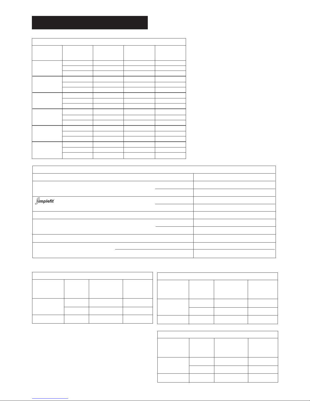
3. Technical Data
HYDRAULIC RESISTANCE
BOILER OUTPUT RESISTANCE MIN. FLOW RATE
kW Metres L/min. °C
0.06 6.5 20
0.13 11.7 11
14.0 0.28 18.2 11
Table 3 9/14CBi
FLUE DETAILS
HORIZONTAL FLUE mm
WALL HOLE DIAMETER EXTERNAL FIX 110
INTERNAL FIX 150
MINIMUM LENGTH 425
MAXIMUM LENGTH 725
EXTENDED FLUE MAXIMUM LENGTH
2.5m (19/24CBi) or 3.0m (9/14 and 14/19CBi)
INTERNAL FLUE - REAR ONLY WITHIN CABINET MINIMUM LENGTH 220
MAXIMUM LENGTH 375
FLUE ASSEMBLY DIAMETER 100
VERTICAL FLUE MINIMUM LENGTH 1100
MAXIMUM LENGTH INCLUDING TERMINAL
3.35m (19/24CBi) or 4.1m (9/14 and 14/19CBi)
Table 2.
FLOW/RETURN
DIFFERENTIAL
NOMINAL BOILER RATINGS (10 Minutes After Lighting)
OUTPUT INPUT (Net) GAS RATE
kW kW m bar. m
3
/h
14.00 15.28 11.0 1.62
11.50 12.70 7.3 1.41
9.00 10.11 4.5 1.07
19.05 20.57 11.5 2.18
16.52 17.96 8.5 1.90
14.00 15.38 6.0 1.63
23.45 25.74 12.0 2.72
21.25 23.35 9.8 2.47
19.05 21.16 7.8 2.24
14.00 15.28 27.2 0.63
12.00 13.18 20.4 0.54
10.00 11.17 15.4 0.45
19.05 20.57 25.4 0.84
16.52 17.96 19.0 0.73
14.00 15.38 13.9 0.63
23.45 25.74 29.9 1.05
21.25 23.35 24.6 0.96
19.05 21.16 20.2 0.87
Table 1. Factory set at maximum input
BURNER
PRESSURE
Natural Gas: Net Input = Gross Input x 0.901
Propane: Net Input = Gross Input x 0.921
NOTE: Pump is fitted externally
9.0
HYDRAULIC RESISTANCE
BOILER OUTPUT RESISTANCE MIN. FLOW RATE
kW Metres L/min. °C
0.09 10 20
0.26 18.2 11
19 .05 0.52 24.8 11
Table 3 14/19CBi
FLOW/RETURN
DIFFERENTIAL
14.0
NOTE: FOR VERTICAL FLUE REFER TO A SEPARATE LEAFLET FOR INFORMATION
HYDRAULIC RESISTANCE
BOILER OUTPUT RESISTANCE MIN. FLOW RATE
kW Metres L/min. °C
0.15 13.7 20
0.52 24.8 11
23.44 0.73 30.5 11
Table 3 19/24CBi
FLOW/RETURN
DIFFERENTIAL
19.05
9/14CBi NG
14/19CBi NG
19/24CBi NG
9/14CBi LPG
14/19CBi LPG
19/24CBi LPG
APPLIANCE
STANDARD TELESCOPIC FLUE KIT
5
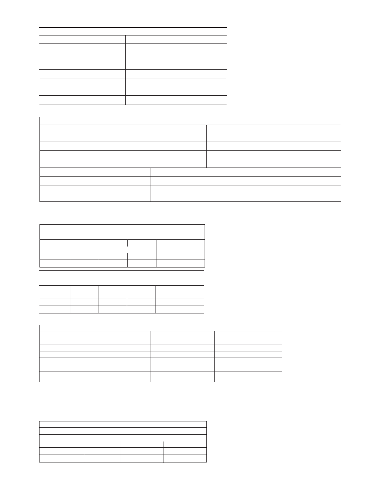
GAS SUPPLY SYSTEM - BASED ON NG (G20)
TOTAL LENGTH OF GAS SUPPLY PIPE (COPPER) metres
3 6 9 12
MAXIMUM GAS DISCHARGE RATE - PRESSURE DROP 1mbar. m3/h PIPE DIAMETER mm
8.7 5.8 4.6 3.9 22
18.0 12.0 9.4 8.0 28
Table 6
CLEARANCES (mm)
INSTALLATION SERVICE
ABOVE APPLIANCE - INTERNAL REAR FLUE 30 30
ABOVE APPLIANCE - EXTERNAL FLUE TURRET 180 180
IN FRONT OF APPLIANCE 600 600
BENEATH APPLIANCE 200 200
RIGHT HAND SIDE 5 5
LEFT HAND SIDE 5 5 *
**
Table 7
SEALED SYSTEM CAPACITY - 10 litre vessel
TOTAL SYSTEM VOLUME litres
INITIAL INITIAL CHARGE PRESSURE bar
PRESSURE bar 0.5 1.0 1.5
1.0 72 92 N/A
1.5 39 53 64
Table 8
PERFORMANCE SPECIFICATIONS
PRIMARY WATER CAPACITY 9/14CBi 1.6 litres 14/19 & 19/24CBi 2.1 litres
STATIC HEAD MINIMUM 1.2M MAXIMUM 30M
MAXIMUM FLOW TEMPERATURE 82°C (nom)
MAXIMUM CENTRAL HEATING SYSTEM OPERATING PRESSURE (Sealed System) 2.5 bar
MINIMUM CENTRAL HEATING SYSTEM SET PRESSURE (Sealed System) 0.12 bar
OUTPUT TO CENTRAL HEATING 9/14CBi 9.0 - 14.0kw 14/19CBi 14.0 - 19.05kw 19/24CBi 19.05 - 23.45kw
NOx CLASSIFICATION FOR CBi APPLIANCES Class 1
SEDBUK NUMBER AND BAND* 9/14CBi NG 78.5 D 14/19CBi NG 79.4 D 19/24CBi NG 78.4 D
9/14CBi LPG 81.0 D 14/19CBi LPG 81.7 D 19/24CBi LPG 80.8 D
Table 5
The appliance can be installed on the above clearance dimensions however, for improved access the following is suggested:
* Improved access - 50mm is recommended
** For improved access minimum clearance when fitted to an adjacent LHS wall is 100mm
NOTE: It is possible to fit the appliance in an unventilated compartment. Refer to Section 6 for details.
MECHANICAL SPECIFICATIONS
FLOW - COPPER TAILS 22mm
RETURN - COPPER TAILS 22mm
GAS INLET 15mm COMPRESSION
CASING HEIGHT 600mm
CASING WIDTH 390mm
CASING DEPTH 260mm
WEIGHT - LIFT 9/14CBi 28kg 14/19 & 19/24CBi 33.5kg
WEIGHT - PACKAGED 9/14CBi 41kg 14/19 & 19/24CBi 47kg
Table 4
GAS SUPPLY SYSTEM - BASED ON PROPANE (G31)
TOTAL LENGTH OF GAS SUPPLY PIPE (COPPER) metres
3 6 9 12 PIPE DIAMETER mm
1.5 — — — 15
8.0 5.2 4.2 3.6 22
15.9 8.8 8.5 7.2 28
* The value is used in the UK Government Standard Assesment Procedure (SAP) for the energy rating of dwellings. The test data from which it has been calculated
have been certified by the GASTEC noified body.
The appliance may be installed in any room subject to the
requirements of the current IEE regulations and, in Scotland, the
relevant electrical provisions of the Building Regulations with
respect to the installation of appliances in rooms containing
baths or showers.
If the appliance is installed in a room containing a bath or
shower, any switch or appliance control using mains electricity
must NOT be able to be touched by a person using the bath or
shower.
The appliance shall not be installed in a room or internal space
below ground level when it is intended for use with LPG propane
(G31). This does not preclude the installation into a room or
space which are basements with respect to one side of the
building but are open to the ground on the opposite side.
The appliance is NOT suitable for external installation.
The wall must be able to support the weight of the appliance.
Refer to Table 4.
The specified clearances must be available for installation and
servicing. Refer to Table 7 and Fig.2.
The appliance can be installed in a cupboard/compartment to
be used for airing clothes providing that the requirements of
BS6798 and BS5440/2 are followed.
The clearance between the front of the appliance and the
cupboard/compartment door should be not less than 25mm for
air circulation.
4. Siting The Appliance
6
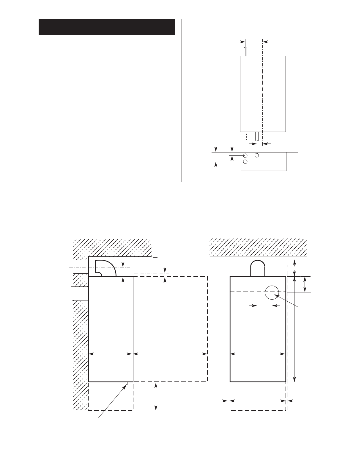
Fig. 2. Appliance casing dimensions and
required clearances.
Side view
260mm
600mm*
30mm*
200mm*
5mm*
* Space required for installation and servicing. Refer to Table 7
Front view
390mm
5mm*
36mm
150mm
600mm
Fig. 3. Appliance pipework connections
Fixing clip
GAS
25mm
36mm
88mm
165mm
FLOW
RETURN
100mm
30mm
(Rear only flue)
Rear only flue
Rear only flue
External
flue turret
142mm
The flue system must be installed following the requirements of
BS5440:1.
The standard flue kit length is 425 - 725mm. Extension kits for
flues up to 3.0m are available.
A rear flue suitable for walls from 220 - 375mm thick is available
which can be contained within the boiler casing.
The terminal must not cause an obstruction nor the combustion
products a nuisance.
If the terminal is less than 2m above a surface to which people
have access then a guard must be fitted. The guard must be
evenly spaced about the terminal and fixed with plated screws.
A guard Type K2 can be obtained from Tower Flue Components,
Vale Rise, Tonbridge, TN9 1TB.
It is essential that products of combustion cannot re-enter the
building. Refer to Fig 4.
A separate vent for combustion air is not required.
The appliance can be fitted in a cupboard or compartment with
no vents for cooling, but the minimum clearances must be
increased to those given below. Refer to BS6798.
Note: the clearance at the front is to a removable panel, e.g. door.
The user must
be informed not to restrict the clearances by the
addition of extra shelves etc and that flammable materials must
not be stored in this compartment.
If the appliance is fitted in a cupboard or compartment with less
clearance than those stated in the table above (minimum
clearances are given in Section 4 Siting the Appliance) then
permanent air vents for cooling are required, one at high level
and one at low level. Both high and low level vents must
communicate with the same room or must be on the same wall
to outside air. The minimum requirements are:
6. Air Supply5. Flue terminal positions
7
L
L
K
K
F
F
G
A
M
EJF
HI
D
G
A
B,C
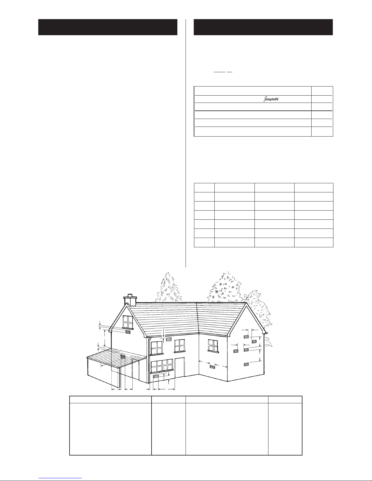
Fig. 4. Siting of the flue terminal.
TERMINAL POSITION MIN. DISTANCE TERMINAL POSITION MIN. DISTANCE
A– directly below an openable window or I– From a terminal facing a terminal 1200mm
other opening e.g. air brick. 300mm J– From an opening in a car port (e.g. door
B– Below gutters, soil pipes or drain pipes.* 75mm window) into dwelling. 1200mm
C– Below eaves.* 25mm K– Vertically from a terminal on the same
D– Below balconies or car port roof.* 25mm wall. 1500mm
E– From vertical drain pipes and soil pipes.* 25mm L– Horizontally from a terminal on the same
F– From internal or external corners. 25mm wall. 300mm
G– Above ground, roof or balcony level. 300mm M– From door, window or air vent.
H– From a surface facing a terminal. 600mm 300mm
Model Position of vent Air from room Air from outside
19/24CBi High 255cm
2
128cm
2
Low 255cm
2
128cm
2
14/19CBi High 207cm
2
104cm
2
Low 207cm
2
104cm
2
9/14CBi High 152cm
2
76cm
2
Low 152cm
2
76cm
2
Above Appliance (when using Rear only Flue) 30mm
Above Appliance (when using horizontal flue) 180mm
In front 340mm
Below 200mm
Right-hand side 105mm
Left-hand side 105mm
If the boiler is fitted between kitchen units and a decorative
door panel is fitted then the top and bottom of the space must
be left open.
*NOTE: A minimum of 75mm must be achieved
where the terminal is near fusible or combustible
material such as plastic drain pipes, guttering or a
carport roof UNLESS suitable heat shields are
provided.
The system must comply with requirements of BS6798 and
BS5449.
General:
The appliance is only suitable for connection to indirect fully
pumped sealed and open vent systems. The minimum static
head is 1.2m and the maximum is 30m.
The pump MUST be wired to the boiler control to ensure that the
pump-overrun function operates to prevent the risk of
overheating and hence nuisance shutdown.
The controls must be wired to ensure that the boiler does not
cycle when electronically controlled zone valves are closed.
A by-pass is required if the controls i.e. 2-port valves, can result
in the closure of the CH and DHW circuits when the boiler is hot.
If mechanically operated thermostatically controlled valves are
fitted on all radiators then a by-pass located at least 2m from the
boiler is required.
A bypass is generally unecessary on a system using a 3 way diverter
valve as one port will be open to flow at all times. This will be
satisfactory for the pump overrun requirement. However if TRV's are
used throughout then a bypass or open radiator may be necessary.
Sealed System:
A sealed system must include an expansion vessel, pressure
relief valve and pressure gauge - these are available as
proprietary kits, the sealed system expansion vessel and fittings
must be connected at the neutral point of the system on the
entry to the pump. A pump and diverter valves are also required
as appropriate to the system. Refer to Fig 5,6,7.
The sealed system must be filled through a WRc approved filling
kit. Refer to Fig.8. The approved method for temporary
connection for filling a closed circuit in a house can be found on
Page 8.25. Fig R24-2a of the Water Regulation Guide and Water
Bylaws 2000 Scotland.
The appliance must not be operated without the system being
full of water and correctly pressurised.
All connections in the system must withstand a pressure of up to
3 bar.
The system and the appliance must be properly vented.
Repeated venting loses water from the system and usually
indicates that there is a leak.
The appliance is NOT suitable for direct water supply.
Do not connect to a direct cylinder.
The CBi can be connected to any indirect cylinder, i.e unvented or
thermal store, and all the benefits of a "dry loft" and mains
pressure hot water can be realised. Contact The Worcester
Technical Helpline. 08705 266241.
Cylinder
Indirect coil type or a direct cylinder with an immersion calorifier
that is suitable for a pressure of 0.35bar above the setting of the
pressure relief valve. Single feed indirect cylinders are NOT
suitable for sealed systems. Any connection to the mains water
supply must conform to the relevant Building and Water
Regulations and be approved by the local Water company.
8. Domestic Hot Water7. System
8
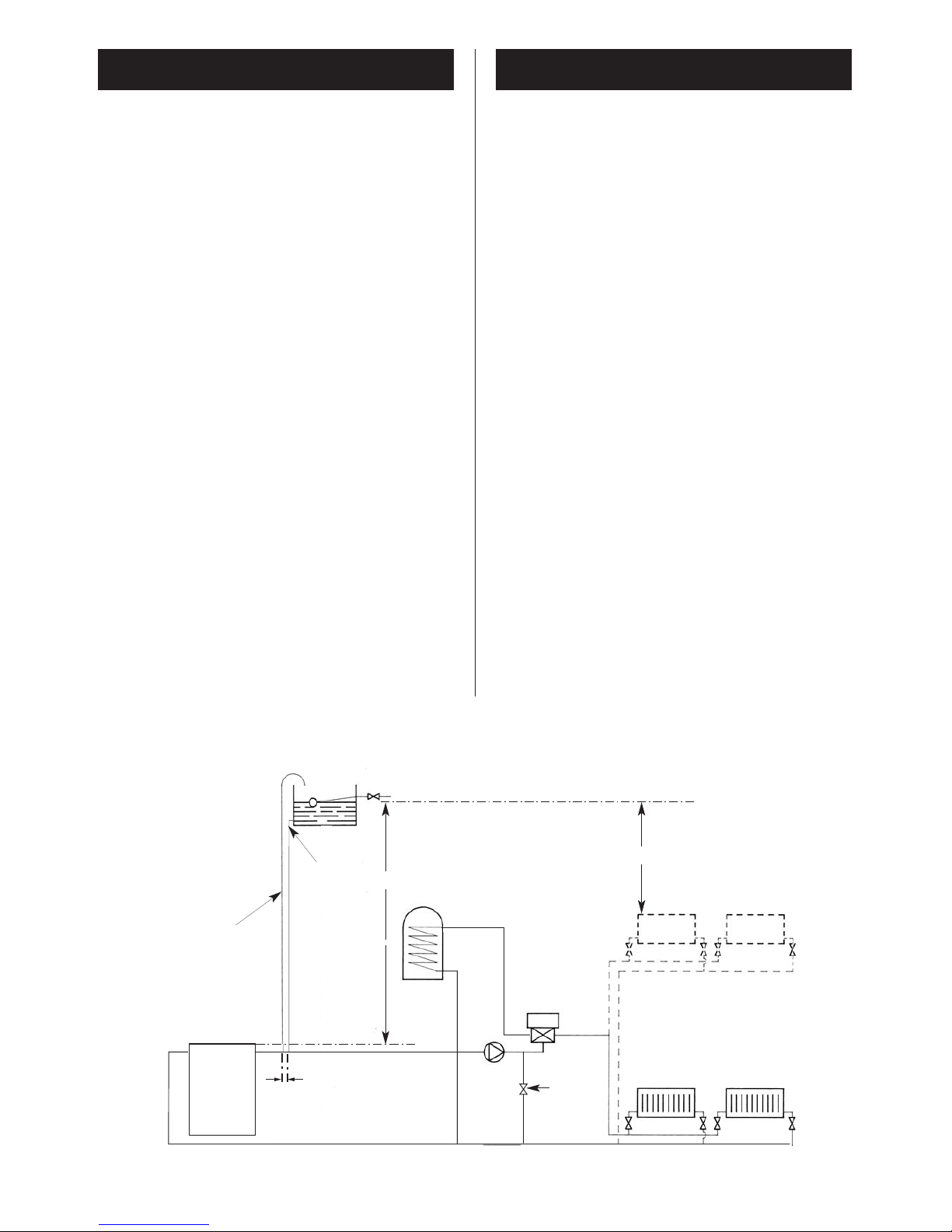
Fig. 5. System layout if using Honeywell 'Y' plan
Primary
cold feed
(15mm min.)
Heating vent
(22mm min.)
Feed and
Vent Cistern
Diverting
valve
Boiler
Pump
Radiator
S.H. – Minimum static head 1.2m
measured from the highest point in the
heating system (top surface of the appliance
or highest point in the heating system) to the
water level in the feed and expansion tank
N.B. A drain cock should be
installed at the lowest point of
the heating circuit
Domestic hot
water cylinder
S.H.
S.H.
150mm max
For system wiring please refer to
Fig. 10. and the controls
manufacturers details.
Bypass or
uncontrolled
radiator
(if required)
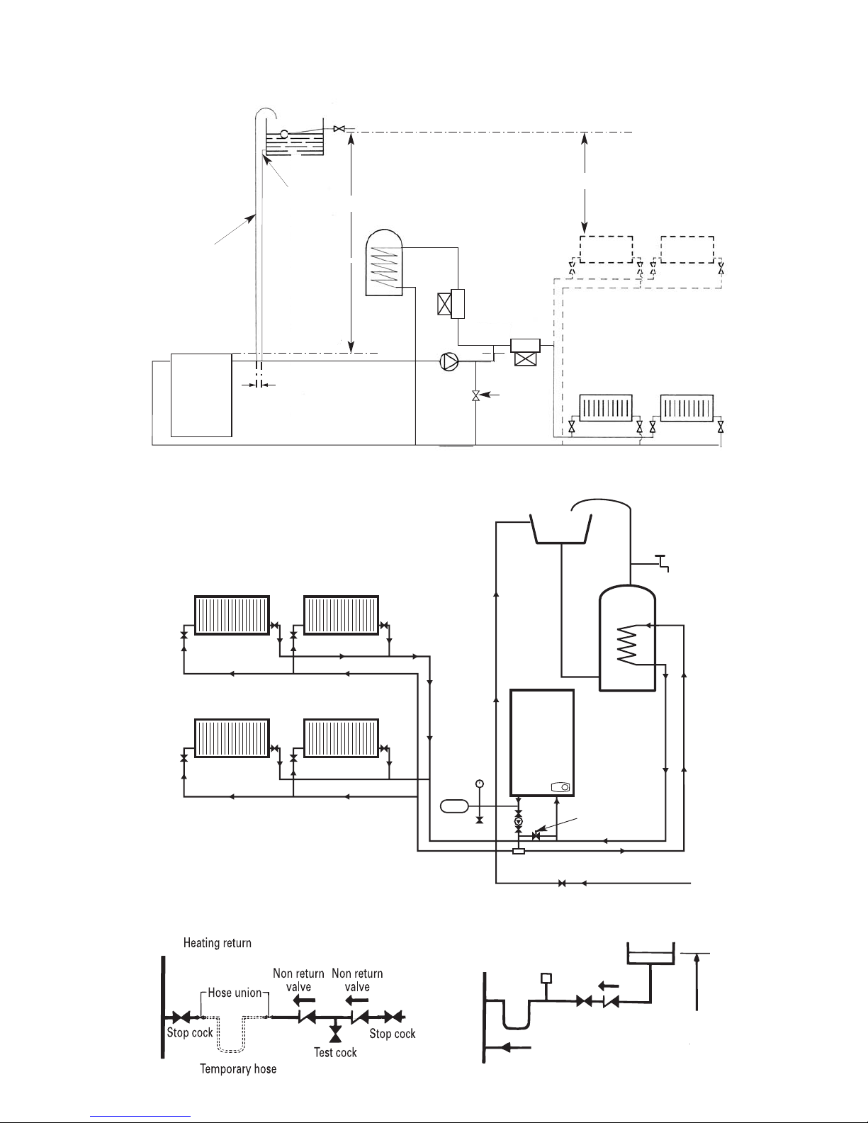
Heating return
Non return
valve
Non return
valve
Hose union
Test cock
Temporary hose
Stop cock
Auto
air vent
Heating return
Stop
cock
Fill point
Non return
valve
Make up
vessel
1200mm (48 in)
above the highest
point of the system.
9
Note:
A drain cock
should be fitted
at the lowest
point of the
heating circuit
and beneath
the appliance
Fig. 7. Fully pumped sealed system.
RV
LV
LV
RV
RV
RV
LV
LV
INDIRECT
CYLINDER
APPLIANCE
Heating Return
Heating Flow
Cylinder Return
Hot Water Flow
BS
Stop Valve Fixed Cylinder Type or sealed systems - Approved connection
Mains Cold Water
Radiator Valve - Flow RV
Lockshield Valve - Return LV
Expansion
Vessel
For system
wiring
please refer to
Fig. 10. and the
controls
manufacturers
details.
Bypass
balancing valve or
bathroom
radiatior with two
lockshield valves
Pressure
Gauge
Relief
Valve
Fig. 8. Sealed system filling and make-up.
Primary
cold feed
(15mm min.)
Heating vent
(22mm min.)
Feed and
Vent Cistern
Diverting
valves
Boiler
Pump
Radiator
S.H. – Minimum static head 1.2m
measured from the highest point in the
heating system (top surface of the appliance
or highest point in the heating system) to the
water level in the feed and expansion tank
N.B. A drain cock should be
installed at the lowest point of
the heating circuit
Domestic hot
water cylinder
S.H.
S.H.
150mm max
Fig. 6. System layout if using Honeywell 'S' plan
For system wiring please refer to
Fig. 10. and the controls
manufacturers details.
Bypass or
uncontrolled
radiator
The gas supplier must be contacted to check the suitability of
the appliance for the local gas supply conditions before
connecting the appliance.
The 19/24CBi appliance requires a maximum of 2.72 m
3
/h of
natural gas (G20), 1.05 m
3
/h propane (G31).
The 14/19CBi appliance requires a maximum of 2.18 m
3
/h of
natural gas (G20), 0.84 m
3
/h propane (G31).
The 9/14CBi appliance requires a maximum of 1.62 m
3
/h of
natural gas (G20), 0.63 m
3
/h propane (G31). Refer to Table 1.
A natural gas appliance must be connected to a governed meter.
The installation of the gas supply to the appliance must be in
accordance with BS6891.
The meter and the pipework to the appliance must be checked,
preferably by the gas supplier, to ensure that a dynamic pressure
of 20mbar for natural gas is available at the appliance
[equivalent to about 19.0 mbar at the gas valve inlet pressure
connection] and that the gas flow is adequate for all the installed
gas appliances or a dynamic pressure of 37 mbar equivalent to
36 mbar at gas valve inlet pressure connection on propane (G31).
Mains Supply: 230V, 50 Hz, 125 watts.
External Fuse: 5A (must be to BS1362).
Internal Fuse: F1 4A (Spare supplied with appliance).
IP Rating: IP 20.
The appliance must be earthed and it must be possible to
completely isolate the appliance.
The mains cable must be 0.75mm
2
(24 x 0.2mm) to
BS6500 - Table 15 or 16
Mains supply to the boiler and system wiring centre must be
through a common fused double pole isolator situated adjacent
to the appliance. The isolator must have a contact separation of
3mm minimum in all poles. A single switched live cable should
be wired into the boiler from the system wiring centre.
The mains and pump cables must be fed through the mains lead
bracket, secured through the cable clamp and connected to the
connector plug. Refer to Fig. 9, 10 and 11.
Frost protection of the boiler is provided on the control board.
A frost thermostat should be considered where parts of the
system are remote from the appliance. For any frost thermostat
function, the boiler temperature control knob must not be set to
the 'OFF' position. The frost thermostat must be fitted to the
system junction box in accordance with the manufacturers
instructions. Refer to Fig. 11.
Safety Check: If there is an electrical fault after installation check
for fuse failure, short circuits, incorrect polarity of connections,
earth continuity or resistance to earth.
10. Electrical
10
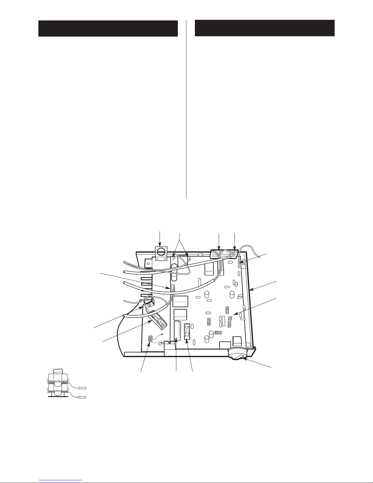
Fig.9 . Mains electricity and controls
connections.
9. Gas Supply
1
1. Base plate
2. Control board
3. Control knob
4. Fuse 4A
5. External control connector block
6. Earth post
7. Cable clamp
8. Internal earth connection
9. Gas valve connection
10. Mains lead bracket
11. Spark electrode connection
12. Air pressure switch, temperature sensor,
overheat thermostat connection
13. Fan connection
14. Flame sense connection
2
3
4
5
6
7
8
9
11
12
13
10
14
Earth post detail.
Note: Pump earth (top connection)
Mains earth (bottom connection)
Pump Earth
Mains Earth
11
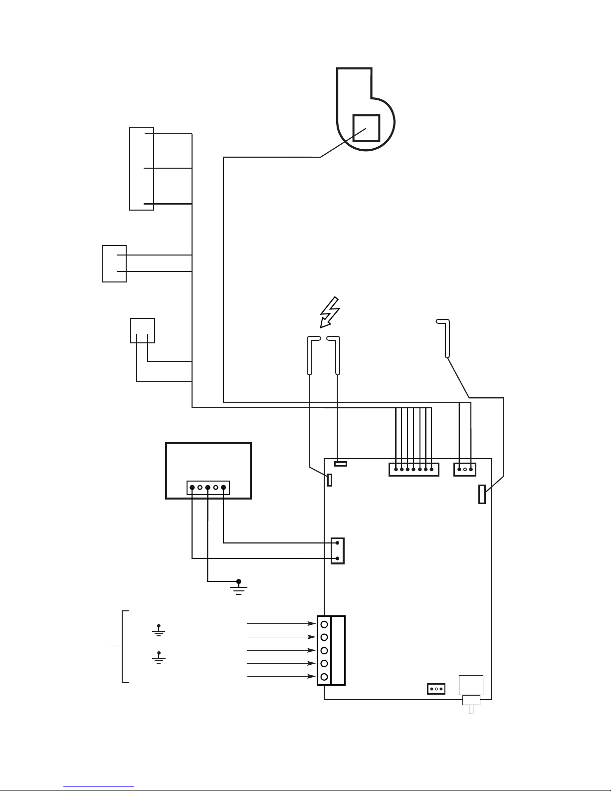
Fig.10. Boiler wiring diagram
Flame
Sense
Electrode
Spark
Electrode
Gas Valve
Air pressure
switch
Overheat
Thermostat
Fan
Control Board
X1
X2
X3
X4
X5
X6
1
orange
1
1
X7
User control
potentiometer/switch
black
white
brown
grey
violet
red
violet
red
black
orange
brown
grey
white
NC
NO
COM
Temperature
sensor
Pump Live
Pump Neutral
Permanent Neutral
Permanent Live
Switched Live (Boiler Demand)
earth
Installer
Connections
blue
brown
*
*
*
Polarity of these connections is not
important.
*
3 pin header
12
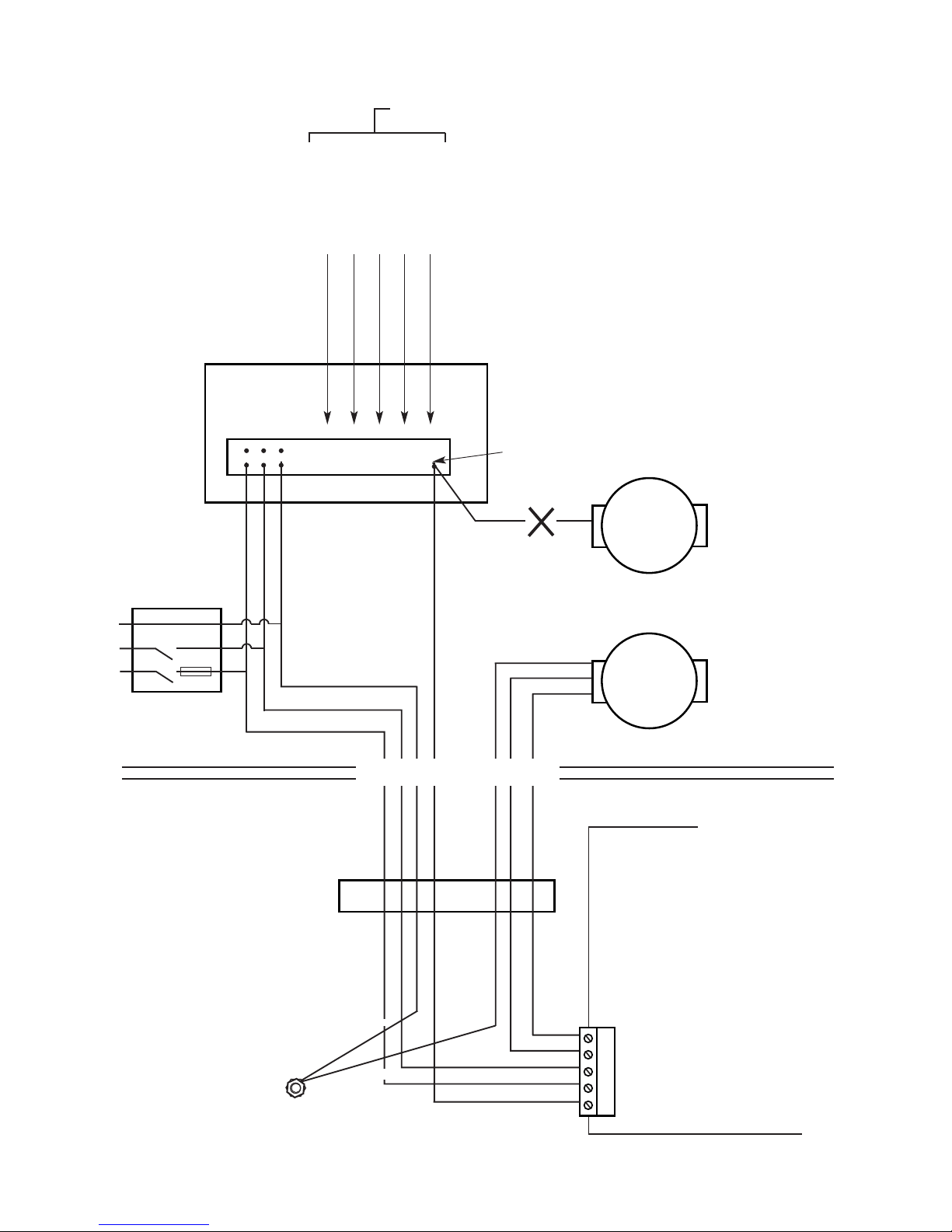
Fig.11 . System wiring diagram
Control Board
X1
Pump L
Pump N
Permanent N
Permanent L
Switched L
(Boiler Demand)
Earth post
Cable clamp
OUTSIDE OF BOILER
INSIDE OF BOILER
System
wiring centre
Terminal strip
Boiler/pump
demand from
system wiring
centre
L switched
Pump not to be
connected to
system wiring
centre
Pump
(supplied from
boiler only)
L
N
E
Timer
Room thermostat
Tank thermostat
System water valves
230V 50Hz
(5A Fuse)
System components wired into terminal strip
in accordance with component manufacturers instructions
Frost stat
Common isolator
for wiring centre
and boiler
Should be located
adjacent to the
boiler
Mains Earth (TOP CONNECTION)
Pump Earth
(BOTTOM CONNECTION)
13
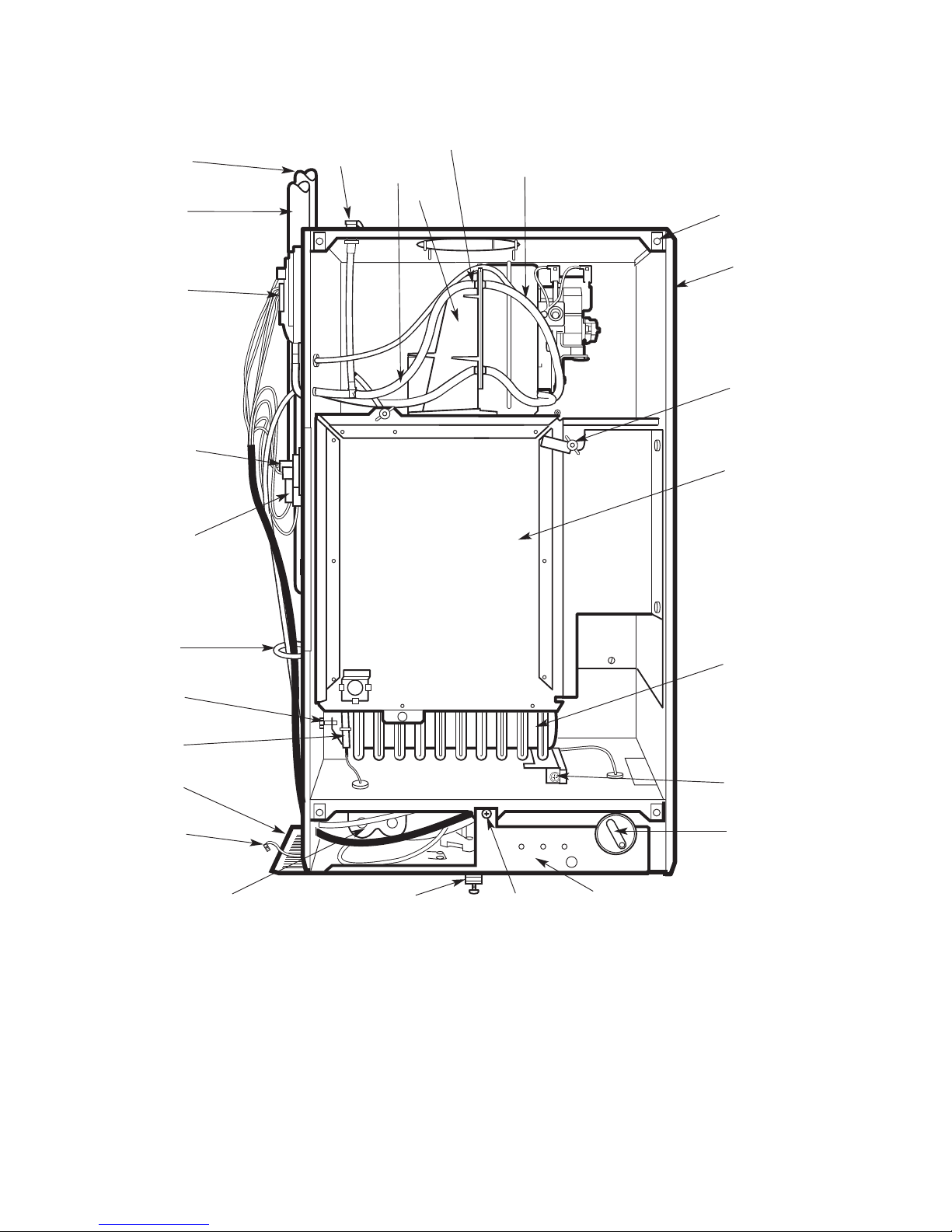
Fig. 12a. Boiler Assembly 9/14CBi
Shown set for Rear Only flue kit
1. Inner case
2. J bolts and wing nuts (2)
3. Combustion chamber cover
4. Burner
5. Burner fixing screw
6. Control knob
7. Indicator lights
8. Base/controls fixing screw
9. Cabinet fixing screw
10. Gas valve
11. Spark electrode
12. Burner injector
13. Temperature sensor
14. Overheat thermostat
15. Air pressure switch
16. Flow pipe
17. Return pipe
18. Combustion test point
19. Sensing tubes
20. Fan
21. Flue hood
22. Inner case cover fixing points (4)
23. Outer case earth tag
24. Side cover plate
25. Wire clip
26. Pressure tube junction
1
2
22
3
4
5
6
7
8
9
10
11
12
13
14
15
16
17
18
19
21
20
23
24
26
25
14
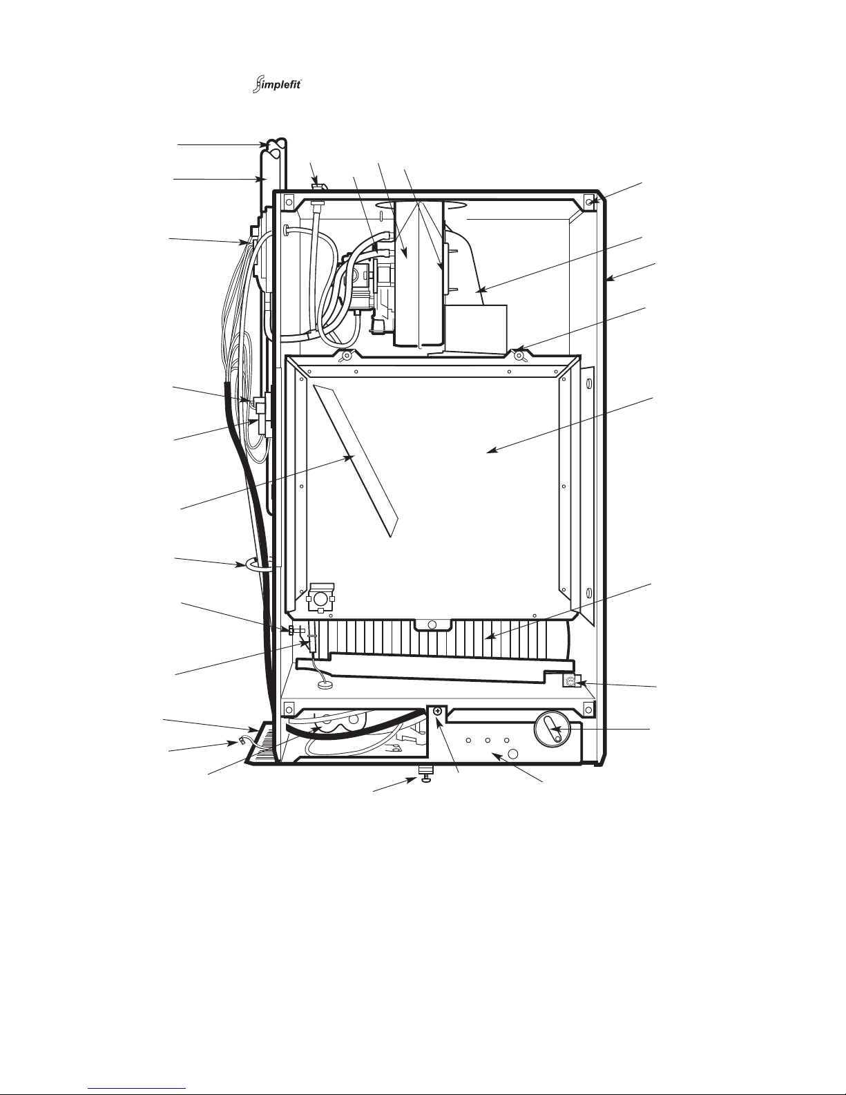
1. Inner case
2. J bolts and wing nuts (2)
3. Combustion chamber cover
4. Burner
5. Burner fixing screw
6. Control knob
7. Indicator lights
8. Base/controls fixing screw
9. Cabinet fixing screw
10. Gas valve
11. Spark electrode
12. Burner injector
13. Temperature sensor
14. Overheat thermostat
15. Air pressure switch
16. Flow pipe
17. Return pipe
18. Combustion test point
19. Sensing tubes
20. Fan
21. Fan clamp (2 screws)
22. Inner case cover fixing points (4)
23. Flue hood
24. Outer case earth tag
25. Side cover plate
26. Wire clip
27. Front baffle
Fig. 12b. Boiler Assembly 14/19 and 19/24CBi
Shown set for horizontal flue or vertical flue
1
2
23
22
3
4
5
6
7
8
9
10
11
12
13
14
15
16
17
18
19
20
21
24
25
27
26
 Loading...