


WR 250 -8 K..G
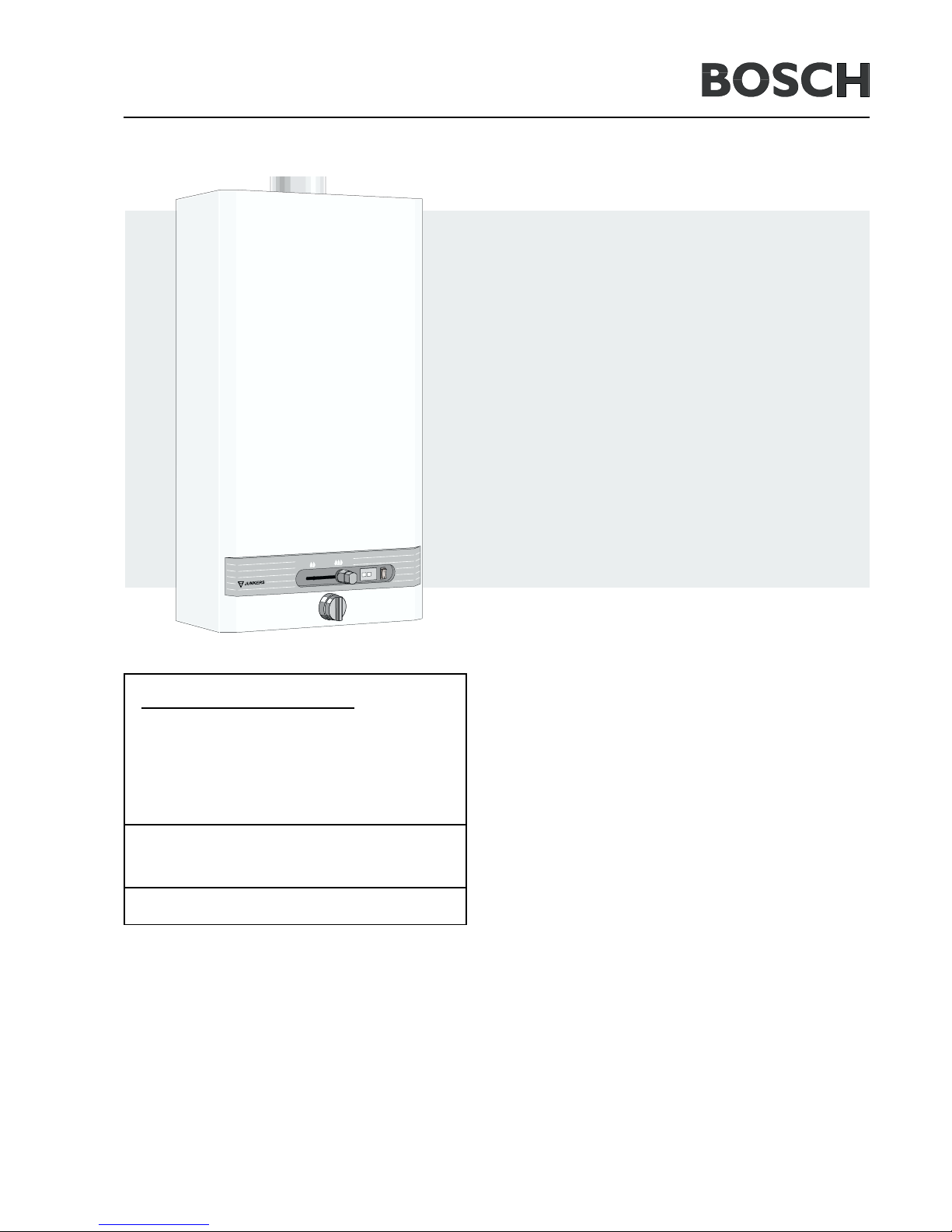
with Hydropower Ignition
Gas Instantaneous Water Heaters
WR 250 -8 K..G..
WR 325 -8 K..G..
WR 400 -8 K..G..
Installation and Operating Instructions
-
THE APPLIANCE MAY ONLY BE INSTALLED BY AN AUTHORISED PERSON.
- Perfect functioning of the appliance is guaranteed only if this specification and the operating instructions are followed.
- The customer shall be provided with these installation instructions.
- The fitter shall explain the function and operation of the appliance to the customer.
- Servicing may only be carried out by authorised personnel.
- Installation in a marine environment should be avoided.
- Install in accordance with AS5601, AS/NZS3500.4.2, NZS5261 and all local building, water and gas fitting regulations.
- Not suitable for pool or SPA application.
- Failure to install the appliance in accordance with these installation instructions may void warranty.
6 720 606 692 (02.05) JS
Approved for indoor installation only.
For your safety
If you smell gas:
1. Close gas isolating cock
2. Open windows
3. Do not actuate any electrical switches
4. Extinguish naked flames
5. Contact gas authorities immediately
Do not store or use flammable materials or liquids
near the appliance.
Do not place articles on or against this appliance.

2 6 720 606 692 (02.05)
W Multipoint gas water heater
R Automatic power adaption
250 Code number 17,5 kW (250 kcal/min)
325 Code number 22,75 kW (325 kcal/min)
400 Code number 28 kW (400 kcal/min)
-8 Version code number
K Chimney flue
V Connector
1 Temperature selector
G Hydropower ignition
23 Gas code number, natural gas H
32 Gas code number, LP gas
S2405 Australian Execution
Page
Index
1. Description of Appliances......................................... 2
1.1 Equipment .......................................................................2
1.2 Type Overview................................................................ 2
1.3 Connecting Measurements ......................................... 3
1.4 Constructional Details .................................................. 3
1.5 Wiring Diagram .............................................................. 4
2. Technical Data ..................................................................... 4
3. Installation............................................................................. 5
3.1 General Remarks .......................................................... 5
3.2 Location ........................................................................... 5
3.3 Connecting Appliance .................................................. 5
3.4 Removal of Front Shell ................................................5
3.5 Water Supply.................................................................. 5
3.6 Gas Connection ............................................................ 5
3.7 Flue ...................................................................................5
3.8 Commissioning ...............................................................5
3.9 HDG Functioning ..........................................................5
4. Servicing ................................................................................ 5
4.1 Setting Appliance .......................................................... 5
4.2 Gas adjustments ........................................................... 5
4.3 Conversion to Other Gases........................................ 6
4.4 Maintenance ................................................................... 6
4.5 Fault Finding ...................................................................7
5. Operating Guide - Quick Reference......................... 8
1.2 Type Overview
Page
1. Description of Appliances
Multipoint gas water heaters with hydropower ignition and
built-in draught diverters for flued connection.
White plastic-coated front casing.
Automatic gas adaption by means of continuous gas control.
Suitable for small and large hot water consumption.
1.1 Equipment
- fully protected with sensor electrode flame failure device;
- hydropower ignition;
- automatic power adaption;
- temperature limiter in power circuit;
- draught diverter.
W R 250 - 8 K V 1 G
23
32
S 2405
W R 325 - 8 K V 1 G
23
32
S 2405
W R 400 - 8 K V 1 G
23
32
S 2405
36 720 606 692 (02.05)
1.4 Constructional Details
1.3 Connecting Measurements
1 Front cover
2 Gas control slide
3 Water flow selector
4 Gas connection
5 Draught diverter
6 Chimney with
draught diverter
7 Heat exchanger
8 Gas valve assembly
9 Ignition unit
10 Water valve
assembly
11 Led failure indicator
12 Led indicator main
burner condition
1 Pilot burner
2 Sparking plug
3 Sensor electrode
4 Heat exchanger
5 Burner
6 Injector nozzle
7a Measuring point (burner)
7b Measuring point (inlet gas)
8 Hydrogenerator
9 Main gas valve
10 Diaphragm (gas)
11 Pilot gas valve
12 Servo valve
13 Slow ignition valve
14 Venturi
15 Gas inlet
16 Water valve
17 Correcting screw for min.
water flow
18 Water flow selector
19 Switch
20 Water governor
21 Water filter
22 Diaphragm (water)
23 Cold water connecting pipe
24 Hot water connecting pipe
25 Ignition unit
26 Gas control slide
27 Poppet valve head
28 Pilot gas pipe
29 Temperature limiter
Diagram 1
Diagram 2
Dimensions
ABC
D
EFG
(mm)
LPG NG
WR 250-8 KG
360 680 228 115 462 162 25 R1/2" R3/4"
WR 350-8 KG
400 755 228 140 500 196 30 R1/2" R3/4"
WR 400-8 KG
460 755 334 140 530 166 30 R1/2" R3/4"
H
 Loading...