


IMPORTANT |
IMPORTANT |
IMPORTANTE |
Read Before Using |
Lire avant usage |
Leer antes de usar |
|
|
|
Operating / Safety Instructions
Consignes d’utilisation / de sécurité
Instrucciones de funcionamiento y seguridad
GWX13-50
GWX13-50VSP
Call Toll Free for Consumer Information & Service Locations
Pour obtenir des informations et les adresses de nos centres de service après-vente, appelez ce numéro gratuit Llame gratis para obtener información para el consumidor y ubicaciones de servicio
1-877-BOSCH99 (1-877-267-2499) www.boschtools.com
For English Version |
Version française |
Versión en español |
See page 2 |
Voir page 30 |
Ver la página 59 |
|
|
|
1600A019ZE 05-19 GWX13.indd 1 |
|
|
5/28/19 3:15 PM |
|
|

pageContentsh ading
Safety Symbols............................................. |
3 |
General Power Tool Safety Warnings........... |
3 |
Work Area Safety........................................ |
3 |
Electrical Safety.......................................... |
3 |
Personal Safety........................................... |
3 |
Power Tool Use and Care........................... |
4 |
Service....................................................... |
4 |
Power Tool-Specific Safety Warnings........... |
5 |
Safety Warnings Common |
|
for Grinding, Sanding, Wire |
|
Brushing, and Abrasive |
|
Cutting-Off Operations............................... |
5 |
Kickback and Related Warnings................. |
6 |
Safety Warnings Specific |
|
for Grinding and Abrasive |
|
Cutting-Off Operations............................... |
6 |
Additional Safety Warnings |
|
Specific for Abrasive |
|
Cutting-Off Operations............................... |
7 |
Safety Warnings Specific for |
|
Sanding Operations.................................... |
7 |
Safety Warnings Specific for Wire Brushing |
|
Operations.................................................. |
7 |
Additional Safety Warnings.......................... |
8 |
Symbols........................................................ |
9 |
Functional Description and Specifications.11 |
|
Basic X-Lock Operation.............................. |
14 |
Assembly.................................................... |
15 |
Installing Side Handle............................... |
15 |
Hand Shield.............................................. |
15 |
Installing Wheel Guards |
|
(Type 27 and Type 41/1A |
|
Wheel Guards).......................................... |
16 |
Mounting and Removing |
|
X-Lock Accessories................................... |
17 |
Abrasive Type 27 Grinding |
|
Wheel & Sanding Flap Disk |
|
Assembly.................................................. |
19 |
Abrasive Type 41/1A |
|
Cutting Wheel Assembly........................... |
19 |
Sanding Assembly ................................... |
20 |
Wire Cup Brush Assembly........................ |
21 |
Wire Wheel Assembly............................... |
21 |
Masonry Cutting Guard |
|
Assembly.................................................. |
22 |
Installing Masonry Type 41/1A |
|
Cutting Guard........................................... |
23 |
Installing Dry Diamond Wheel.................. |
23 |
Operating Instructions............................... |
24 |
Paddle Switch (Fig. 21)............................ |
24 |
Slide Switch (Fig. 23)............................... |
24 |
Metal Grinding.......................................... |
25 |
Metal Cutting............................................ |
25 |
Masonry / Concrete Cutting..................... |
26 |
Sanding.................................................... |
27 |
Wire Brush (Wheels and Cups)................ |
28 |
Maintenance............................................... |
28 |
Service..................................................... |
28 |
Tool Lubrication........................................ |
28 |
Carbon Brushes........................................ |
29 |
Cleaning................................................... |
29 |
Accessory Storage & |
|
Maintenance............................................. |
29 |
Extension Cords......................................... |
29 |
Accessories................................................ |
29 |
-2-
1600A019ZE 05-19 GWX13.indd 2 |
|
|
5/28/19 3:15 PM |
|
|
Safetypage headingSymbols
The definitions below describe the level of severity for each signal word. Please read the manual and pay attention to these symbols.
This is the safety alert symbol. It is used to alert you to potential personal injury hazards. Obey all safety messages that follow this symbol to avoid possible injury or death.
DANGER indicates a hazardous situation which, if not avoided, will result in death or serious injury.
WARNING indicates a hazardous situation which, if not avoided, could result in death or serious injury.
CAUTION indicates a hazardous situation which, if not avoided, could result in minor or moderate injury.
General Power Tool Safety Warnings
Read all safety warnings and all instructions. Failure to follow the warnings and instructions may result in electric shock, fire and/or seri-
ous injury.
SAVE ALL WARNINGS AND INSTRUCTIONS FOR FUTURE REFERENCE
The term “power tool” in the warnings refers to your mains-operated (corded) power tool or battery-operated (cordless) power tool.
Work Area Safety
Keep work area clean and well lit. Cluttered or dark areas invite accidents.
Do not operate power tools in explosive atmospheres, such as in the presence of flammable liquids, gases or dust. Power tools create sparks which may ignite the dust or fumes.
Keep children and bystanders away while operating a power tool. Distractions can cause you to lose control.
Electrical Safety
Power tool plugs must match the outlet. Never modify the plug in any way. Do not use any adapter plugs with earthed (grounded) power tools. Unmodified plugs and matching outlets will reduce risk of electric shock.
Avoid body contact with earthed or grounded surfaces, such as pipes, radiators, ranges and refrigerators. There is an increased risk of electric shock if your body is earthed or grounded.
-3-
Do not expose power tools to rain or wet conditions. Water entering a power tool will increase the risk of electric shock.
Do not abuse the cord. Never use the cord for carrying, pulling or unplugging the power tool. Keep cord away from heat, oil, sharp edges or moving parts.
Damaged or entangled cords increase the risk of electric shock.
When operating a power tool outdoors, use an extension cord suitable for outdoor use. Use of a cord suitable for outdoor use reduces the risk of electric shock.
If operating a power tool in a damp location is unavoidable, use a Ground Fault Circuit Interrupter (GFCI) protected supply. Use of an GFCI reduces the risk of electric shock.
Personal Safety
Stay alert, watch what you are doing and use common sense when operating a power tool. Do not use a power tool while you are tired or under the influence of drugs, alcohol or medication. A moment of inattention while operating power tools may result in serious personal injury.
1600A019ZE 05-19 GWX13.indd 3 |
|
|
5/28/19 3:15 PM |
|
|
General Power Tool Safety Warnings
Use personal protective equipment. Always wear eye protection. Protective equipment such as dust mask, non-skid safety shoes, hard hat, or hearing protection used for appropriate conditions will reduce personal injuries.
Prevent unintentional starting. Ensure the switch is in the off-position before connecting to power source and / or battery pack, picking up or carrying the tool.
Carrying power tools with your finger on the switch or energizing power tools that have the switch on invites accidents.
Remove any adjusting key or wrench before turning the power tool on. A wrench or a key left attached to a rotating part of the power tool may result in personal injury.
Do not overreach. Keep proper footing and balance at all times. This enables better control of the power tool in unexpected situations.
Dress properly. Do not wear loose clothing or jewelry. Keep your hair, clothing and gloves away from moving parts.
Loose clothes, jewelry or long hair can be caught in moving parts.
If devices are provided for the connection of dust extraction and collection facilities, ensure these are connected and properly used. Use of dust collection can reduce dust-related hazards.
Power Tool Use and Care
Do not force the power tool. Use the correct power tool for your application. The correct power tool will do the job better and safer at the rate for which it was designed.
Do not use the power tool if the switch does not turn it on and off. Any power tool that cannot be controlled with the switch is dangerous and must be repaired.
Disconnect the plug from the power source and/or the battery pack from the power tool before making any adjustments, changing accessories, or storing power tools. Such preventive safety measures reduce the risk of starting the power tool accidentally.
Store idle power tools out of the reach of children and do not allow persons unfamiliar with the power tool or these instructions to operate the power tool.
Power tools are dangerous in the hands of untrained users.
Maintain power tools. Check for misalignment or binding of moving parts, breakage of parts and any other condition that may affect the power tool’s operation. If damaged, have the power tool repaired before use. Many accidents are caused by poorly maintained power tools.
Keep cutting tools sharp and clean. Properly maintained cutting tools with sharp cutting edges are less likely to bind and are easier to control.
Use the power tool, accessories and tool bits etc. in accordance with these instructions, taking into account the working conditions and the work to be performed. Use of the power tool for operations different from those intended could result in a hazardous situation.
Service
Have your power tool serviced by a qualified repair person using only identical replacement parts. This will ensure that the safety of the power tool is maintained.
-4-
1600A019ZE 05-19 GWX13.indd 4 |
|
|
5/28/19 3:15 PM |
|
|

Power Tool-Specific Safety Warnings
Safety Warnings Common for Grinding, Sanding, Wire Brushing, and Abrasive Cutting-Off Operations
This power tool is intended to function as a grinder, sander, wire brush or cut-off tool. Read all safety warnings, instructions, illustrations and specifications provided with this power tool. Failure to follow all instructions listed below may result in electric shock, fire and/or serious injury.
Operations such as polishing are not recommended to be performed with this power tool. Operations for which the power tool was not designed may create a hazard and cause personal injury.
Do not use accessories which are not specifically designed and recommended by the tool manufacturer. Just because the accessory can be attached to your power tool, it does not assure safe operation.
The rated speed of the accessory must be at least equal to the maximum speed marked on the power tool. Accessories running faster than their rated speed can break and fly apart.
The outside diameter and the thickness of your accessory must be within the capacity rating of your power tool. Incorrectly sized accessories cannot be adequately guarded or controlled.
Threaded mounting of accessories must match the grinder spindle thread. For accessories mounted by flanges, the arbour hole of the accessory must fit the locating diameter of the flange. Accessories that do not match the mounting hardware of the power tool will run out of balance, vibrate excessively and may cause loss of control.
Do not use a damaged accessory. Before each use inspect the accessory such as abrasive wheels for chips and cracks, backing pad for cracks, tear or excess wear, wire brush for loose or cracked wires. If power tool or accessory is dropped, inspect for damage or install
an undamaged accessory. After inspecting and installing an accessory, position yourself and bystanders away from the plane of the rotating accessory and run the power tool at maximum no-load speed for one minute. Damaged accessories will normally break apart during this test time.
Wear personal protective equipment. Depending on application, use face shield, safety goggles or safety glasses. As appropriate, wear dust mask, hearing protectors, gloves and workshop apron capable of stopping small abrasive or workpiece fragments. The eye protection must be capable of stopping flying debris generated by various operations. The dust mask or respirator must be capable of filtrating particles generated by your operation. Prolonged exposure to high intensity noise may cause hearing loss.
Keep bystanders a safe distance away from work area. Anyone entering the work area must wear personal protective equipment. Fragments of workpiece or of a broken accessory may fly away and cause injury beyond immediate area of operation.
Hold the power tool by insulated gripping surfaces only, when performing an operation where the cutting accessory may contact hidden wiring or its own cord. Cutting accessory contacting a “live” wire may make exposed metal parts of the power tool “live” and could give the operator an electric shock.
Position the cord clear of the spinning accessory. If you lose control, the cord may be cut or snagged and your hand or arm may be pulled into the spinning accessory.
Never lay the power tool down until the accessory has come to a complete stop.
The spinning accessory may grab the surface and pull the power tool out of your control.
Do not run the power tool while carrying it at your side. Accidental contact with the spinning accessory could snag your clothing, pulling the accessory into your body.
-5-
1600A019ZE 05-19 GWX13.indd 5 |
|
|
5/28/19 3:15 PM |
|
|

Power Tool-Specific Safety Warnings
Regularly clean the power tool’s air vents. The motor’s fan will draw the dust inside the housing and excessive accumulation of powdered metal may cause electrical hazards.
Do not operate the power tool near flammable materials. Sparks could ignite these materials.
Do not use accessories that require liquid coolants. Using water or other liquid coolants may result in electrocution or shock.
Only use Bosch or Bosch licensed X-Lock accessories. Incompatible accessories may not clamp properly resulting in personal injury and/or property damage.
Confirm proper clamping by ensuring that top of the accessory flange surface is not above the top of the accessory height gage. Accessories that are above the accessory height gage may not be clamped properly and separate from the tool causing personal injury and/or property damage.
Always inspect accessory mount and accessory clamping flange before use. Do not use the tool or accessory if the accessory mount or accessory is damaged or deformed. Accessories that are not clamped properly may cause personal injury and/or property damage.
Check for presence or buildup of foreign material on tool and accessory clamping surfaces and remove before use. Unwanted material can cause incomplete clamping and may cause personal injury and/or property damage.
Never actuate X-Lock Release Lever while accessory is moving. Make sure that the accessory has come to a complete stop before removing the accessory. Releasing accessory while still spinning could cause personal injury and/or property damage.
direction opposite of the accessory’s rotation at the point of the binding.
For example, if an abrasive wheel is snagged or pinched by the workpiece, the edge of the wheel that is entering into the pinch point can dig into the surface of the material causing the wheel to climb out or kickout. The wheel may either jump toward or away from the operator, depending on direction of the wheel’s movement at the point of pinching. Abrasive wheels may also break under these conditions.
Kickback is the result of power tool misuse and/or incorrect operating procedures or conditions and can be avoided by taking proper precautions as given below.
Maintain a firm grip on the power tool and position your body and arm to allow you to resist kickback forces. Always use auxiliary handle, if provided, for maximum control over kickback or torque reaction during start-up. The operator can control torque reactions or kickback forces, if proper precautions are taken.
Never place your hand near the rotating accessory. Accessory may kickback over your hand.
Do not position your body in the area where power tool will move if kickback occurs. Kickback will propel the tool in direction opposite to the wheel’s movement at the point of snagging.
Use special care when working corners, sharp edges etc. Avoid bouncing and snagging the accessory. Corners, sharp edges or bouncing have a tendency to snag the rotating accessory and cause loss of control or kickback.
Do not attach a saw chain woodcarving blade or toothed saw blade. Such blades create frequent kickback and loss of control.
Kickback and Related Warnings
Kickback is a sudden reaction to a pinched or snagged rotating wheel, backing pad, brush or any other accessory. Pinching or snagging causes rapid stalling of the rotating accessory which in turn causes the uncontrolled power tool to be forced in the
Safety Warnings Specific for Grinding and Abrasive Cutting-Off Operations
Use only wheel types that are recommended for your power tool and the specific guard designed for the selected
-6-wheel. Wheels for which the power tool
1600A019ZE 05-19 GWX13.indd 6 |
|
|
5/28/19 3:15 PM |
|
|
Power Tool-Specific Safety Warnings
was not designed cannot be adequately guarded and are unsafe.
The grinding surface of centre depressed wheels must be mounted below the plane of the guard lip. An improperly mounted wheel that projects through the plane of the guard lip cannot be adequately protected.
The guard must be securely attached to the power tool and positioned for maximum safety, so the least amount of wheel is exposed towards the operator. The guard helps to protect operator from broken wheel fragments and accidental contact with wheel.
Wheels must be used only for recommended applications. For example: do not grind with the side of cut-off wheel.
Abrasive cut-off wheels are intended for peripheral grinding, side forces applied to these wheels may cause them to shatter.
Always use undamaged wheel flanges that are of correct size and shape for your selected wheel. Proper wheel flanges support the wheel thus reducing the possibility of wheel breakage. Flanges for cut-off wheels may be different from grinding wheel flanges.
Do not use worn down wheels from larger power tools. Wheel intended for larger power tool is not suitable for the higher speed of a smaller tool and may burst.
When wheel is binding or when interrupting a cut for any reason, switch off the power tool and hold the power tool motionless until the wheel comes to a complete stop. Never attempt to remove the cut-off wheel from the cut while the wheel is in motion otherwise kickback may occur. Investigate and take corrective action to eliminate the cause of wheel binding.
Do not restart the cutting operation in the workpiece. Let the wheel reach full speed and carefully reenter the cut. The wheel may bind, walk up or kickback if the power tool is restarted in the workpiece.
Support panels or any oversized workpiece to minimize the risk of wheel pinching and kickback. Large workpieces tend to sag under their own weight. Supports must be placed under the workpiece near the line of cut and near the edge of the workpiece on both sides of the wheel.
Use extra caution when making a “pocket cut” into existing walls or other blind areas. The protruding wheel may cut gas or water pipes, electrical wiring or objects that can cause kickback.
Do not use type 1 abrasive wheels designed for straight grinding.
Do not attempt to cut large stock or sheets of metal as this machine is not designed to be a dedicated cut-off machine.
Additional Safety Warnings Specific for Abrasive Cutting-Off Operations
Do not “jam” the cut-off wheel or apply excessive pressure. Do not attempt to make an excessive depth of cut. Overstressing the wheel increases the loading and susceptibility to twisting or binding of the wheel in the cut and the possibility of kickback or wheel breakage.
Do not position your body in line with and behind the rotating wheel. When the wheel, at the point of operation, is moving away from your body, the possible kickback may propel the spinning wheel and the power tool directly at you.
-7-
Safety Warnings Specific for Sanding Operations
Do not use excessively oversized sanding disc paper. Follow manufacturer’s recommendations, when selecting sanding paper. Larger sanding paper extending beyond the sanding pad presents a laceration hazard and may cause snagging, tearing of the disc or kickback.
Safety Warnings Specific for Wire Brushing Operations
Be aware that wire bristles are thrown by the brush even during ordinary operation. Do not overstress the wires by applying excessive load to the brush. The
1600A019ZE 05-19 GWX13.indd 7 |
|
|
5/28/19 3:15 PM |
|
|
Power Tool-Specific Safety Warnings
wire bristles can easily penetrate light clothing and/or skin.
If the use of a guard is recommended for wire brushing, do not allow any interfer-
ence of the wire wheel or brush with the guard. Wire wheel or brush may expand in diameter due to work load and centrifugal forces.
Additional Safety Warnings
Do not use AC only rated tools with a DC power supply. While the tool may appear to work, the electrical components of the AC rated tool are likely to fail and create a hazard to the operator.
Keep handles dry, clean and free from oil and grease. Slippery hands cannot safely control the power tool.
Use clamps or other practical way to secure and support the workpiece to a stable platform. Holding the work by hand or against your body is unstable and may lead to loss of control.
Develop a periodic maintenance schedule for your tool. When cleaning a tool be careful not to disassemble any portion of the tool since internal wires may be misplaced or pinched or safety guard return springs may be improperly mounted.
Certain cleaning agents such as gasoline, carbon tetrachloride, ammonia, etc. may damage plastic parts.
Do not use vacuum or other dust collection system when cutting metal. Sparks from metal cutting can cause fire in the collector.
Some dust created by power sanding, sawing, grinding, drilling, and other construction
activities contains chemicals known to cause cancer, birth defects or other reproductive harm. Some examples of these chemicals are:
•Lead from lead-based paints,
•Crystalline silica from bricks and cement and other masonry products, and
•Arsenic and chromium from chemicallytreated lumber.
Your risk from these exposures varies, depending on how often you do this type of work. To reduce your exposure to these chemicals: work in a well ventilated area, and work with approved safety equipment, such as those dust masks that are specially designed to filter out microscopic particles.
-8-
1600A019ZE 05-19 GWX13.indd 8 |
|
|
5/28/19 3:15 PM |
|
|
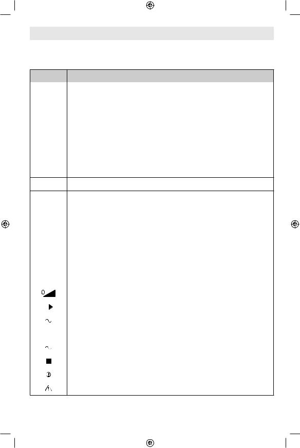
pageSymbolsheading
Important: Some of the following symbols may be used on your tool. Please study them and learn their meaning. Proper interpretation of these symbols will allow you to operate the tool better and safer.
Symbol |
Designation/Explanation |
|
|
V |
Volts (voltage) |
|
|
A |
Amperes (current) |
|
|
Hz |
Hertz (frequency, cycles per second) |
|
|
W |
Watt (power) |
|
|
kg |
Kilograms (weight) |
|
|
min |
Minutes (time) |
|
|
s |
Seconds (time) |
Diameter (size of drill bits, grinding wheels, etc.)
|
|
n0 |
No load speed (rotational speed, at no load) |
|||||
|
|
n |
Rated speed (Maximum attainable speed) |
|||||
|
|
|
|
|
|
|
|
|
.../min |
Revolutions or reciprocation per minute (revolutions, strokes, surface |
|||||||
speed, orbits etc. per minute) |
||||||||
|
|
|
|
|
|
|
||
|
|
|
|
|
|
|
|
|
0 |
|
Off position (zero speed, zero torque...) |
||||||
|
|
|
|
|
|
|
|
|
1, 2, 3, ... |
Selector settings (speed, torque or position settings. Higher number |
|||||||
I, II, III, |
means greater speed) |
|||||||
|
|
|
|
|
|
|
|
|
|
|
|
|
|
|
|
Infinitely variable selector with off (speed is increasing from 0 setting) |
|
|
|
|
|
|
|
|
|
|
|
|
|
|
|
|
|
Arrow (action in the direction of arrow) |
|
|
|
|
|
|
|
|
||
|
|
|
|
|
|
|
|
|
|
|
|
|
|
|
|
Type or a characteristic of current |
|
|
|
|
|
|
|
|
|
|
|
|
|
|
|
|
|
Type or a characteristic of current |
|
|
|
|
|
|
|
|
||
|
|
|
|
|
|
|
|
|
|
|
|
|
|
|
|
Type or a characteristic of current |
|
|
|
|
|
|
|
|
||
|
|
|
|
|
|
|
|
|
|
|
|
|
|
|
|
Designates Double Insulated Construction tools |
|
|
|
|
|
|
|
|
|
|
|
|
|
|
|
|
|
Grounding terminal |
|
|
|
|
|
|
|
|
||
|
|
|
|
|
|
|
|
|
|
|
|
|
|
|
|
Alerts user to warning messages |
|
-9-
1600A019ZE 05-19 GWX13.indd 9 |
|
|
5/28/19 3:15 PM |
|
|

pageSymbolsheading
Important: Some of the following symbols may be used on your tool. Please study them and learn their meaning. Proper interpretation of these symbols will allow you to operate the tool better and safer.
Symbol Designation/Explanation
Designates Li-ion battery recycling program.
Designates Ni-Cad battery recycling program.
Alerts user to read manual.
Alerts user to wear eye protection.
This symbol designates that this tool is listed by Underwriters Laboratories.
This symbol designates that this component is recognized by Underwriters Laboratories.
This symbol designates that this tool is listed by Underwriters Laboratories, to United States and Canadian Standards.
This symbol designates that this tool is listed by the Canadian Standards Association.
This symbol designates that this tool is listed by the Canadian Standards Association, to United States and Canadian Standards.
This symbol designates that this tool is listed by the Intertek Testing Services, to United States and Canadian Standards.
This symbol designates that this tool complies to NOM Mexican Standards.
-10-
1600A019ZE 05-19 GWX13.indd 10 |
|
|
5/28/19 3:15 PM |
|
|
Functional Descriptionpageheadingand Specifications
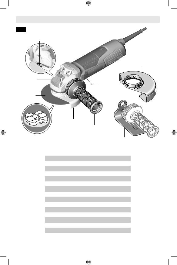
Fig. 1
Guard Release /
Adjustment Button
X-Lock
Release
Lever
Grinding
Wheel
Type 27
Grinding
Guard
X-Lock
Accessory
Mount
Model Number
Amps
Volts AC
Rated Speed (RPM), /min
Max. grinding wheel
Grinding wheel thickness
Max. cutting wheel
Max. sanding disc
Max. flap disc
Max. wire wheel
Max. wire cup
Variable speed
Electronic clutch
Constant response circuitry
Restart protection
Overload protection
Soft start
Variable Speed (GWX13-50VSP)


 6
6 

 Lock-ON Button
Paddle Switch
“Lock-OFF” Switch
Release Lever
Vibration
Control Side
Handle
|
Hand Shield |
|
(Optional Accessory) |
GWX13-50VSP |
|
13 |
|
120 |
|
2800 - 11500 |
|
5” (125mm) |
|
1/4” (6 mm) |
Type 41/1A |
5” (125mm) |
Cutting Guard |
5” (125mm) |
(Optional Accessory) |
|
|
5” (125mm) |
|
4” (102mm) |
|
3” (76mm) |
|
● |
|
● |
|
● |
|
● |
|
● |
|
● |
|
-11-
1600A019ZE 05-19 GWX13.indd 11 |
|
|
5/28/19 3:15 PM |
|
|
Functional Descriptionpageheadingand Specifications
Fig. 2
Guard Release /
Adjustment Button
X-Lock
Release Lever
Grinding
Wheel
Type 27
Grinding
Guard
X-Lock
Accessory
Mount
Model Number
Type 41/1A
Cutting Guard
(Optional Accessory)
Side
Switch
Vibration
Control Side
Handle
Hand Shield
(Optional Accessory)
GWX13-50
Amps |
13 |
Volts AC |
120 |
Rated Speed (RPM), /min |
11500 |
Max. grinding wheel |
5” (125mm) |
Grinding wheel thickness |
1/4” (6 mm) |
Max. cutting wheel |
5” (125mm) |
Max. sanding disc |
5” (125mm) |
Max. flap disc |
5” (125mm) |
Max. wire wheel |
4” (102mm) |
Max. wire cup |
3” (76mm) |
Electronic clutch |
● |
Constant response circuitry |
● |
Restart protection |
● |
Overload protection |
● |
Soft start |
● |
|
|
-12-
1600A019ZE 05-19 GWX13.indd 12 |
|
|
5/28/19 3:15 PM |
|
|
Functional Descriptionpageheadingand Specifications
Do not use Type 11 abrasive (cup) wheels with this tool. This tool is not designed for use with type 11 (cup) abrasive grinding wheels.
Model Number |
GWX13-50 |
GWX13-50VSP |
Metal Grinding (Type 27) |
X |
X |
Metal Grinding (Type 11) |
N |
N |
Metal Grinding (Type 1) |
N |
N |
Metal Cutting (Type 41/1A) |
O |
O |
Flap Disc Type 29 |
X |
X |
Concrete Cutting |
O |
O |
Sanding |
O |
O |
Wire Brushing (Wheel) |
X |
X |
Wire Brushing (Cup) |
O |
O |
|
|
|
X = Tool is provided with attachments to perform this application. O = Tool can use optional attachments to perform this application. N = Tool is not capable of this application.
Accessory speed rating must be equal to or greater than the tool’s speed rating. Do not exceed the recommended wheel diameter.
-13-
1600A019ZE 05-19 GWX13.indd 13 |
|
|
5/28/19 3:15 PM |
|
|
Basic X-Lock Operation
The X-Lock system is a combination of patented tool mount and accessory designs that provide the operator with fast accessory changes. Available on select Bosch angle grinders, X-Lock allows tool free installation and removal of grinder accessories (grinding, cut-off wheels, wire brushes, sanding discs, etc.). The X-Lock system is a replacement for the traditional method of attaching grinder accessories.
Traditional grinders have 5/ 8”-11 threaded spindles that require a nut and backing flange to hold the accessory in place. To replace an accessory, a wrench is used to loosen or tighten the nut. X-Lock equipped grinders have a tool free interface system, eliminating the spindle, backing flange and lock nut.
The X-Lock interface has a tool component
– X-Lock Accessory Mount, and an accessory component – typically an Accessory X-Lock Mounting Hub. The two components have keyed alignment contours, which help to ensure correct assembly of accessory to tool.
The X-Lock Accessory Mount consists of a round base, clamping height gages and locking mechanism, which activates the clamping tabs. X-Lock equipped grinders can only use X-Lock accessories since the specially designed X-Lock Mounting Hub matches the contours of the X-Lock Accessory Mount on the tool (See figure 3). However, select X-Lock accessories are backward compatible with the traditional threaded spindle design.
Attachment of the X-Lock accessory to the X-Lock Accessory Mount on the grinder requires alignment of the mounting hub with the accessory mounting mechanism. Once the Accessory X-Lock Mounting Hub is aligned, and pressed against the base of the X-Lock Accessory Mount, the locking mechanism is activated. This causes the two opposing clamping tabs to lock the accessory to the grinder. An audible ‘click’ in combination with the alignment of the flat surface of the Accessory X-Lock Mounting hub with the Clamping Height Gages means the accessory is firmly attached to the tool. To remove the accessory, a lever
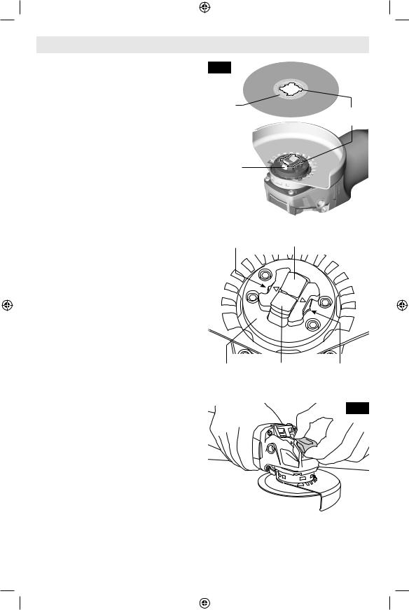
Fig. 3
Accessory
X-Lock
Mounting Hub Alignment
contours
X-Lock
Accessory
Mount
Clamping |
Clamping Tab |
Height Gage |
Base |
Clamping Tab |
Clamping |
|
|
Height Gage |
|
|
Fig. 4 |
on the grinder gearhead is actuated which will release the locking tabs, allowing the accessory to be detached from the tool. (Fig. 4)
-14-
1600A019ZE 05-19 GWX13.indd 14 |
|
|
5/28/19 3:15 PM |
|
|

Assembly
Disconnect the plug from the power source and/or remove the battery pack, if detachable, from the power tool before making any adjustments, changing accessories, or storing power tools. Such preventive safety
measures reduce the risk of starting the power tool accidentally.
Hand Shield
(Optional Accessory)
Fig. 5
Side
Handle
Installing Side Handle
The side handle is used to control and balance the tool.
Securely thread handle into either side of gear housing, depending on personal preference, comfort, and operation being performed (Fig. 5).
The handle should always be installed onto the guard protected side of the tool, see figure 7. Use the side handle for safe control and ease of operation.
Hand Shield
The hand shield is to be used with backing pads, sanding discs, and wire brushes to keep fingers and hand away from work surface, sharp edges, burrs and debris.
When using the hand shield, insert side handle through hole in shield and then thread into housing (Fig. 5). Ensure that hand shield is positioned between hand and backing pad, sanding disc or wire brush.
-15-
1600A019ZE 05-19 GWX13.indd 15 |
|
|
5/28/19 3:15 PM |
|
|
Assembly
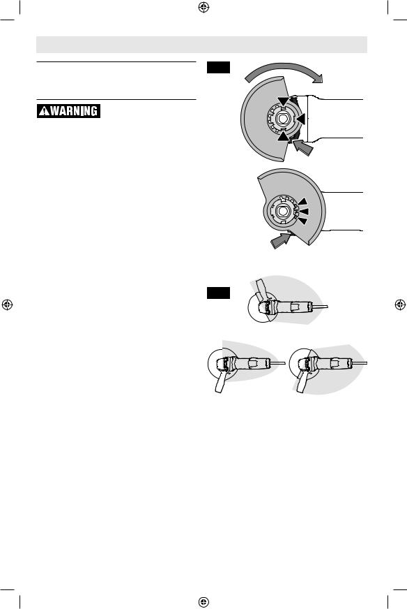
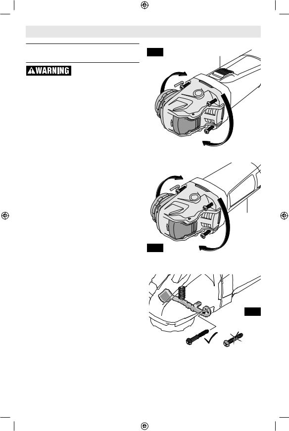
Installing Wheel Guards (Type 27 and Type 41/1A Wheel Guards)
A Type 27 guard must be used with all grinding wheels, bonded body sanding flap
discs, wire brushes and wheels. The tool may be used without a guard only when sanding with conventional sanding discs.
▼▼To attach guard
1.Unplug tool from power source.
2.Position appropriate guard on collar mount so arrows on guard and collar mount align (Fig. 6).
3.Rotate wheel guard clockwise 90º until guard clicks in place.
4.Adjust guard by depressing guard release button and rotate to desired position. Always position wheel guard between operator and work piece and direct sparks away from operator (Fig. 7).
5.Allow guard release button to click in place.
▼▼To remove wheel guard
1.Depress guard release button and rotate guard until arrows on guard and collar mount align (Fig. 6).
2.Remove guard from collar mount.
Fig. 6
Fig. 7
OPERATING ZONE
-16-
1600A019ZE 05-19 GWX13.indd 16 |
|
|
5/28/19 3:15 PM |
|
|
pageAssemblyheading
Mounting and Removing X-Lock Accessories
Only use Bosch or Bosch licensed X-LOCK accessories. Incompatible accessories
may not clamp properly resulting in personal injury and/or property damage.
Confirm proper clamping by ensuring that top of the accessory X-Lock mounting hub
surface is not above the top of the clamping height gage. Accessories that are above the clamping height gage may not be fixed properly and separate from the the tool causing personal injury and/or property damage.
Always inspect accessory mount and accessory clamping flange before use. Do not
use the tool or accessory if the accessory mount or accessory is damaged or deformed. Accessories that are not clamped properly may cause personal injury and/or property damage.
Check for presence or buildup of foreign material on clamping surfaces and remove be-
fore use. Unwanted material can cause incomplete clamping and may cause personal injury and/or property damage.
Never actuate X-Lock Release Lever while accessory is moving. Make sure that the ac-
cessory has come to a complete stop before removing the accessory. Releasing accessory while still spinning could cause personal injury and/or property damage.
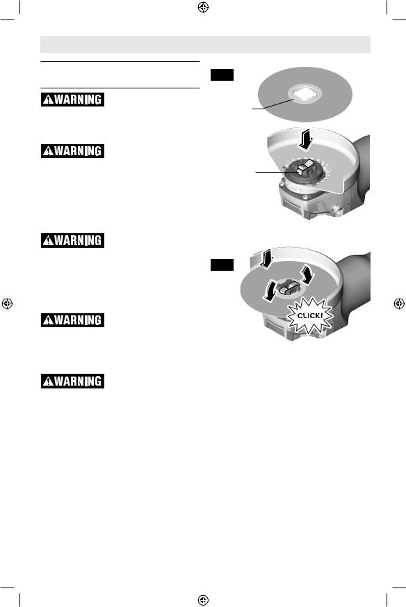
Verify that the accessory and the X-Lock Accessory Mount are not deformed and are free from dirt. If necessary, clean the area around the two X-Lock Clamping Tabs.
Verify that both X-Lock Clamping Tabs are open (see Fig. 8) before fitting the X-Lock accessory.
Fig. 8
Accessory
X-Lock
Mounting Hub
X-Lock
Accessory
Mount
Fig. 9
▼▼Mounting accessory to the tool
1.Place the accessory on the X-Lock Accessory Mount, by aligning the alignment contours of the Accessory X-Lock Mounting Hub with the X-Lock Accessory Mount on the grinder (Fig. 8).
2.Push the accessory into the X-Lock Accessory Mount. The accessory audibly clicks as the Clamping Tabs lock into place (Fig. 9).
3.Check that the edge of the Accessory X-Lock Mounting Hub is correctly engaged in the slots of the X-Lock Clamping Tabs (Fig. 10). If the top surface of the Accessory X-Lock Mounting Hub is higher than the Clamping Height Gage (located on each side of the X-Lock Accessory Mount), the X-Lock accessory
-17-
1600A019ZE 05-19 GWX13.indd 17 |
|
|
5/28/19 3:15 PM |
|
|

Assembly
must not be used until this condition is eliminated by cleaning the X-Lock Accessory Mount or replacing the accessory.
▼▼Removing accessories
Never actuate X-Lock Release Lever while accessory is moving. Make sure that the ac-
cessory has come to a complete stop before removing the accessory. Releasing accessory while still spinning could cause personal injury and/or property damage.
Do not touch grinding and cutting discs until they have cooled down. The discs can be-
come very hot while working.
Do not allow accessories to fall uncontrollably after release. Falling accessories can
become damaged and may cause personal injury and/or property damage.
Do not use a damaged accessory. Before each use inspect the accessory such as abra-
sive wheels for chips and cracks, backing pad for cracks, tear or excess wear, wire brush for loose or cracked wires. If power tool or accessory is dropped, inspect for damage or install an undamaged accessory. After inspecting and installing an accessory, position yourself and bystanders away from the plane of the rotating accessory and run the power tool at maximum no-load speed for one minute. Damaged accessories will normally break apart during this test time.
Before removing the accessory: Make sure that the power tool has come to a complete stop and is disconnected from power.
1.Orient the tool to prevent the accessory from being dropped during release.
2.Open the X-Lock Release Lever (Fig. 11):
(A)Press on the backside of the lever.
(B)Lift the front-side of the lever.
3.Remove the accessory from the tool with care, preventing it from being dropped.
Clamping |
Clamping Tabs |
|
Height Gage |
|
Fig. 10 |
Accessory |
|
X-Lock |
Clamping |
|
|||
Mounting Hub |
Height Gage |
||
CORRECT: Height of Accessory X-Lock Mounting Hub is equal or less than X-Lock Accessory Mount
X-Lock Accessory |
Accessory X-Lock |
Mount |
Mounting Hub |
INCORRECT: Height of Accessory X-Lock Mounting Hub is greater than X-Lock Accessory Mount
X-Lock Accessory |
Accessory X-Lock |
Mount |
Mounting Hub |
(A)
Fig. 11
(B) 
-18-
1600A019ZE 05-19 GWX13.indd 18 |
|
|
5/28/19 3:15 PM |
|
|
Assembly
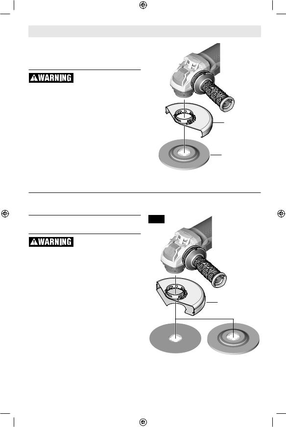
Abrasive Type 27 Grinding |
|
Fig. 12 |
Wheel & Sanding Flap Disk |
|
|
Assembly |
|
|
Do not use accessories that run eccentrically.
The tool will vibrate excessively and may cause loss of control and the accessory may burst.
To install grinding wheel or flap disk (Fig. 12) see instructions on page 17.
Type 27
Wheel Guard
Type 27
Grinding
Wheel
Abrasive Type 41/1A Cutting Wheel Assembly
Always use type 41/1A cutting guard for cutting operations. Other guards or attach-
ments may not protect operator in the event of a wheel burst.
To install cutting wheel (Fig. 13) see instructions on page 17.
Fig. 13
Type 41/1A
Wheel Guard
Type 41/1A |
Type 27 |
Cutting Wheel |
Cutting Wheel |
-19-
1600A019ZE 05-19 GWX13.indd 19 |
|
|
5/28/19 3:15 PM |
|
|
Assembly
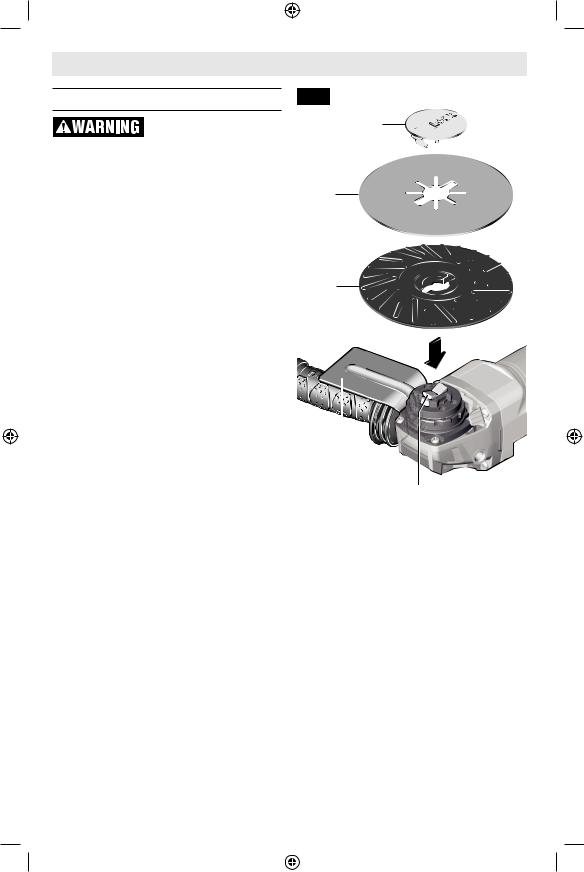
Sanding Assembly
A type 27 wheel guard may not be used for all tool operations. Do not discard guard
when not in use. Always reinstall wheel guard when converting back to grinding operations.
The Hand Shield is to be used with backing pads, sanding discs and wire brushes to keep fingers and hand away from work surface, sharp edges, burs and debris. When using the Hand Shield accessory, insert side handle through hole in shield and then thread into housing (Fig. 5). Ensure that hand shield is positioned between hand and backing pad, sanding disc or wire brush.
▼▼To install backing pad and sanding disc (Fig. 14)
1.Inspect Hand Shield to ensure that it is properly attached to the grinder.
2.Place the Backing Pad onto the X-Lock Accessory Mount with the rectangular openings positioned around the X-Lock Clamping Tabs.
3.Center the Sanding Disc on top of the Backing Pad and align the rectangular cut-outs with the Clamping Tabs on the X-Lock Accessory Mount.
4.Align the X-Lock Clip with the slots in the Sanding Disc. Insert the X-Lock Clip through the Sanding Disc and apply pressure to it, until it is fully engaged by the Clamping Tabs, which will be indicated by an audible “click”.
5.To remove the sanding assembly from the grinder, follow instructions for Mounting and Removing X-Lock Accessories starting on page 17.
Fig. 14
X-Lock
Clip
Sanding
Disc
Backing
Pad
Hand
Shield
Clamping
Tabs
-20-
1600A019ZE 05-19 GWX13.indd 20 |
|
|
5/28/19 3:15 PM |
|
|
pageAssemblyheading
Wire Cup Brush Assembly
A type 27 wheel guard may not be used for all tool operations. Do not discard guard
when not in use. Always reinstall wheel guard when converting back to grinding operations. When using Wire Cup Wheels, tool may be used without a guard.
Wear protective gloves when handling wire brush accessories. Handling of wire brush
accessories without gloves may result in personal injury.
▼▼To install wire cup brush (Fig. 15)
Follow instructions for Mounting and Removing X-Lock Accessories starting on page 15.
Wire Wheel Assembly
▼▼To install wire wheel (Fig. 16)
1.Inspect and adjust Type 27 Grinding Guard to the proper position, as shown in figure 7 on page 16.
2.Follow instructions for “Mounting accessory to the tool” and “Removing the accessories on page 17.
Fig. 15
Wire Cup
Brush Hand
Shield
Fig. 16
Type 27
Wheel Guard


 Wire Wheel
-21-
1600A019ZE 05-19 GWX13.indd 21 |
|
|
5/28/19 3:15 PM |
|
|
pageAssemblyheading
Masonry Cutting Guard Assembly
A type 27 grinding wheel guard may not be used for all tool operations. Do not dis-
card guard when not in use. Always reinstall wheel guard when converting back to grinding operations.
For cutting masonry, gearbox must be rotated relative to the position of the switch as the tool was assembled at the factory.
▼▼Rotate Gearbox
1.Completely unscrew the four screws between the gear housing and motor body.
2.Rotate gear housing to the proper orientation without removing motor from the housing.
a.For the slide switch models (Fig. 17), rotate gear housing 180 degrees, so the switch is 90 degrees from the X-Lock Accessory Mount.
b.For the paddle switch models (Fig. 18), rotate gear housing 90 degrees, so the switch is facing the work piece.
3.After adjusting the position of the gear housing, screw in and tighten the four screws.
4.The screw holding the guard release lever is longer than the other screws (Fig. 19), this long screw must stay with the guard release lever when re-attaching gear housing for the guard release button to operate properly.
5.To install proper guard follow instructions in the next section.
Fig. 17
180 DEGREES
90 DEGREES
Fig. 18
Slide
Switch
180 DEGREES
Paddle
Switch
Under Tool
90 DEGREES
Fig. 19
-22-
1600A019ZE 05-19 GWX13.indd 22 |
|
|
5/28/19 3:15 PM |
|
|
pageAssemblyheading
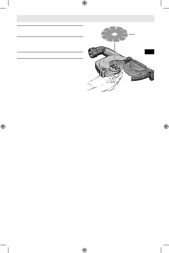
Installing Masonry Type 41/1A Cutting Guard
Follow all instructions provided with the masonry Type 41/1A cutting guard to install and use it with this grinder.
Installing Dry Diamond Wheel
Follow all instructions provided with the masonry Type 41/1A cutting guard to prepare it for installation of compatible accessories and operation.
To install Dry Diamond Wheel (Fig. 20) see instructions on page 17.
-23-
Dry Diamond
Wheel
Fig. 20
1600A019ZE 05-19 GWX13.indd 23 |
|
|
5/28/19 3:15 PM |
|
|
Operating Instructions
Never leave the trigger locked “ON”. Before plugging the tool in, check that the trigger
lock is “OFF”. Accidental start-ups could cause injury.
Be aware of the location and setting of the switch “Lock-ON” button. If the switch is
locked “ON” during the use, be ready for emergency situations to switch it “OFF”.
Do not use the switch “Lock-ON” feature in situations where kickback is likely, such
as when working into a corner. When the wheel binds, the tool will kick-back in opposite direction of wheel rotation and the release of the trigger “Lock-ON” may be difficult.
If the “Lock-ON” button is continuously being depressed, the trigger cannot be re-
leased.
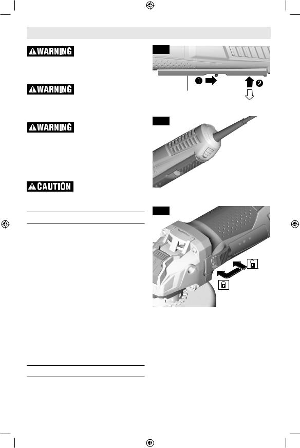
Paddle Switch (Fig. 21)
The paddle switch has a Lock-OFF feature to help prevent accidental startups. TO TURN TOOL “ON”, push Lock-Off switch backward to unlock the paddle switch, then squeeze paddle switch. TO TURN TOOL “OFF”, release pressure on paddle switch. The switch is spring loaded and will return to the “OFF” position automatically.
If your tool has the Lock-ON feature incorporated into the paddle switch for extended operation, there will be a red button on the bottom of the tool directly behind the paddle switch, Fig. 22. TO LOCK SWITCH “ON” after paddle switch has been activated, push “Lock-ON” button while simultaneously releasing pressure from the paddle switch. TO TURN TOOL “OFF”, squeeze and release paddle switch.
Slide Switch (Fig. 23)
TO TURN TOOL ON, press the back of the switch and slide it forward towards the gear housing until it comes to a stop and
Fig. 21
|
ON |
Paddle Switch |
OFF |
Fig. 22
 Lock-ON Button
Fig. 23
Side
Switch
the motor starts running. For Lock-ON, when the switch is in the ON position, press the front of the switch and release it. the switch should remain in the LockON position and the tool will continue to run.
TO TURN TOOL “OFF”, press the rear portion of the switch. The switch is spring loaded and will return to the “OFF” position automatically.
-24-
1600A019ZE 05-19 GWX13.indd 24 |
|
|
5/28/19 3:15 PM |
|
|

Operating Instructions
Metal Grinding
Grinding wheels should be carefully selected in order to use the grinder most efficiently. Wheels vary in type of abrasive, bond, hardness, grit size and structure. The correct wheel to use is determined by the job. Use disc grinding wheels for fast grinding of structural steel, heavy weld beads, steel casting, stainless steel and other ferrous metals.
1.Allow the tool to reach full speed before touching the tool to the work surface.
2.Apply minimum pressure to the work surface, allowing the tool to operate at high speed. Grinding rate is greatest when the tool operates at high speed.
3.Maintain a 10° to 15° angle between the tool and work surface, (Fig. 24).
Fig. 24
4.Continuously move the tool at a moderate speed to avoid creating gouges in the work surface.
5.Remove the tool from work surface before turning tool off. Allow the tool to stop rotating before laying it down.
Tip: When grinding with a new wheel be certain to grind while pulling tool backwards until the wheel becomes rounded on its edge. New wheels have sharp edges which tend to “bite” or cut into the work piece when pushed forward.
Metal Cutting
A Type 1 wheel guard may not be included with this tool but is required when using
a cutting wheel. Cutting with a type 27 wheel guard may not provide the operator sufficient protection in the event of a wheel burst.
With this grinder it is possible to perform cutting of limited small stock such as metal tubes, piping or rebar. When cutting, work with moderate feed, adapted to the material being cut. When cutting profiles and square bar, it is best to start at the smallest cross section.
Always follow precautions for kickback.
1.Allow the tool to reach full speed before touching the tool to the work surface.
2.The tool should always be used in such way that the sparks are directed away from user.
3.Apply minimum pressure to the work surface, allowing the tool to operate
Fig. 25
at high speed. Cutting rate is greatest when the tool operates at high speed.
4.Do not exert side pressure onto the cutting disc. Do not tilt or oscillate the tool as wheel may burst, (Fig. 25).
5.Remove the tool from the work surface before turning the tool off. Allow the tool to stop rotating before laying it down.
-25-
1600A019ZE 05-19 GWX13.indd 25 |
|
|
5/28/19 3:15 PM |
|
|
OperatingpageheadingInstructions
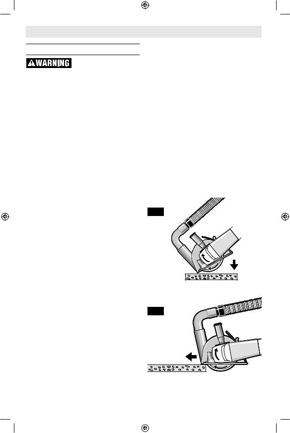
Masonry / Concrete Cutting
Never pull the tool backward since blade will climb out of the material and KICK-
BACK will occur.
With this grinder it is possible to perform cutting of concrete and masonry materials. When cutting, work with moderate feed, adapted to the material being cut.
Always follow precautions for kickback.
Operate the tool with a dust extraction system and personal dust protection, e.g. respirator, dust mask, etc. The vacuum used for this application must be approved for the extraction of masonry and concrete dust. Bosch sells suitable vacuum cleaners.
1.Allow the tool to reach full speed before touching the tool to the work surface.
2.If plunge cutting:
a.Tilt tool forward with wheel lined up with the cut line and hold the tool by the grinder body and the auxiliary handle (Fig. 26).
b.Gradually lower the rear of tool using the front end of the foot as the hinge point.
c.When the foot rests flat on the surface being cut, proceed cutting in forward direction to end of cut.
3.Always maintain contact between the guard foot and work piece.
4.Slide the tool forward at a moderate speed adapted to the material being cut. Always cut towards the dust extraction port to maximize dust extraction and reduce likelihood of kickback (Fig. 27).
5.Apply minimum pressure to the work surface, allowing the tool to operate at high speed. Cutting rate is greatest when the tool operates at high speed.
6.When the cut is completed, remove tool from work piece before turning off. Allow wheel to stop rotating before setting tool down.
Tip: When performing deep cuts, it is best to cut in several shallow passes. Each pass should be only to the segment depth of the wheel. Masonry dust is abrasive and may wear and weaken the segment bond.
When cutting especially hard material, e. g., concrete with high pebble content, the dry diamond wheel can overheat and become damaged. This is clearly indicated by circular sparking of the rotating dry diamond wheel. In this case, interrupt the cutting process and allow the dry diamond wheel to cool by running the tool for a short period of time at the maximum speed with no-load.
Noticeable decreasing work progress and circular sparking are indications of a dry diamond wheel that has become dull. Briefly cutting into abrasive materials (e. g. brick) can resharpen the wheel.
Fig. 26
Fig. 27
-26-
1600A019ZE 05-19 GWX13.indd 26 |
|
|
5/28/19 3:15 PM |
|
|

OperatingpageheadingInstructions
Sanding
Sanding discs range in grit from 16 (very course) to 180 (very fine). They also vary in size and spacing of grit.
OPEN COAT (type H) is used for soft materials and on paint and varnish, CLOSED COAT (type K) is used for metal, hardwood, stone, marble and other materials. To obtain best results, select sanding discs carefully. Many jobs require the use of several grit sizes and at times both open coat and closed coat discs are required to complete the job. See chart for application examples.
1.Allow the tool to reach full speed before touching the tool to the work surface.
2.Apply minimum pressure to the work surface, allowing the tool to operate at high speed. Sanding rate is greatest when the tool operates at high speed.
Fig. 28
3.Maintain a 10° to 15° angle between the tool and work surface, (Fig. 28).
4.Continuously move the tool at a moderate speed to avoid creating gouges in the work surface.
5.Remove the tool from work surface before turning tool off. Allow the tool to stop rotating before laying it down.
Tip: Guide the disc with crisscross strokes. Do not use a circular motion as this makes swirl marks.
Operation: Refinishing painted wood or metal surfaces.
REMARKS |
GRIT |
|
|
To remove paint and to smooth surface irregularities. |
Coarse 16-24-30 |
|
|
To smooth the rough sanding. |
Medium 36-50-80 |
|
|
To remove scratches left by previous discs. |
Fine 100-120 |
|
|
To smooth surfaces for painting, polishing or waxing. |
Very Fine 150-180 |
|
|
-27-
1600A019ZE 05-19 GWX13.indd 27 |
|
|
5/28/19 3:15 PM |
|
|
 Loading...