


GWS PROFESSIONAL 21-180/230 (J)HV
Bosch GWS PROFESSIONAL 21-180/230 (J)HV, GWS PROFESSIONAL 24-180/230 (J)BV, GWS PROFESSIONAL 26-180/230 (J)BV Operating Instructions Manual
* Des idées en action.
Bedienungsanleitung
Operating instructions
Instructions d’emploi
Instrucciones de servicio
Manual de instruções
Istruzioni d’uso
Gebruiksaanwijzing
Betjeningsvejledning
Bruksanvisning
Brukerveiledningen
Käyttöohje
Οδηγία χειρισµού
Kullan∂m k∂lavuzu
GWS 21-180/230 (J)HV
GWS 24-180/230 (J)BV
GWS 26-180/230 (J)BV
PROFESSIONAL
2 • 1 609 929 F55 • 04.01
1 605 703 099
1 600 210 039
1 603 340 031
1 603 340 040
1 607 950 048
2 602 025 124
1 601 329 013
1 605 510 222
1 605 510 223
2 605 510 173
2 605 510 174
1 600 793 007
1 605 510 179
1 605 510 180
F
Ø 180 mm
Ø 230 mm
Ø 180 mm
Ø 230 mm
Ø 180 mm
Ø 230 mm
16
24
36
60
24
36
60
METAL
1 607 000 247
1 605 510 181
1 605 703 099
1 608 600 231
1 608 600 232
1 608 600 233
1 608 600 234
1 608 600 239
1 608 600 240
1 608 600 241
1 603 340 040
1 607 950 004
0 601 999 018
0 601 999 019
1 605 438 034
3 • 1 609 929 F55 • 04.01
4+5 • 1 609 929 F55 • 04.01
26
25
13 12 10
27 28
GWS 24-180 (J)BV
GWS 24-230 (J)BV
GWS 26-180 (J)BV
GWS 26-230 (J)BV
PROFESSIONAL
1
10
11
13
3
24
21
22
23
2
6
12
19 19
16
10
17
12
20
7
9
8
14
15
5
18
GWS 21-180 (J)HV
GWS 21-230 (J)HV
PROFESSIONAL
4

Deutsch - 1
Das Gerät ist bestimmt zum Trennen, Schruppen
und Bürsten von Metall- und Steinwerkstoffen
ohne Verwendung von Wasser. Zum Trennen
von Stein ist ein Führungsschlitten vorgeschrieben.
Schlitze in tragenden Wänden unterliegen der
Norm DIN 1053 Teil 1 oder länderspezifischen
Festlegungen.
Diese Vorschriften sind unbedingt einzuhalten.
Vor Arbeitsbeginn den verantwortlichen Statiker,
Architekten oder die zuständige Bauleitung zu
Rate ziehen.
Messwerte ermittelt entsprechend EN 50 144.
Der A-bewertete Geräuschpegel des Gerätes be-
trägt typischerweise: Schalldruckpegel
90 dB (A); Schallleistungspegel 103 dB (A).
Gehörschutz tragen!
Die Hand-Arm-Vibration ist typischerweise niedriger als 2,5 m/s
2
(1,7 m/s
2
).
Gerätekennwerte
Winkelschleifer GWS 21-180 HV
PROFESSIONAL
GWS 21-230 HV
PROFESSIONAL
GWS 24-180 BV
PROFESSIONAL
Bestellnummer 0 601 851 B.. 0 601 852 B.. 0 601 853 B..
Mit Anlaufstrombegrenzung GWS 21-180 JHV
PROFESSIONAL
GWS 21-230 JHV
PROFESSIONAL
GWS 24-180 JBV
PROFESSIONAL
Bestellnummer 0 601 851 G.. 0 601 852 G.. 0 601 853 G..
Nennaufnahmeleistung* [W] 2 100 2 100 2 400
Abgabeleistung [W] 1 350 1 350 1 700
Leerlaufdrehzahl [min
-1
] 8 500 6 500 8 500
Schleifscheiben-Ø, max. [mm] 180 230 180
Schleifspindelgewinde M 14 M 14 M 14
Gewicht ohne Netzkabel, ca. [kg] 4,4 4,4 5,2
Schutzklasse
/ II / II / II
Winkelschleifer GWS 24-230 BV
PROFESSIONAL
GWS 26-180 BV
PROFESSIONAL
GWS 26-230 BV
PROFESSIONAL
Bestellnummer 0 601 854 B.. 0 601 855 B.. 0 601 856 B..
Mit Anlaufstrombegrenzung GWS 24-230 JBV
PROFESSIONAL
GWS 26-180 JBV
PROFESSIONAL
GWS 26-230 JBV
PROFESSIONAL
Bestellnummer 0 601 854 G.. 0 601 855 G.. 0 601 856 G..
Nennaufnahmeleistung* [W] 2 400 2 600 2 600
Abgabeleistung [W] 1 700 1 800 1 800
Leerlaufdrehzahl [min
-1
] 6 500 8 500 6 500
Schleifscheiben-Ø, max. [mm] 230 180 230
Schleifspindelgewinde M 14 M 14 M 14
Gewicht ohne Netzkabel, ca. [kg] 5,2 5,2 5,2
Schutzklasse
/ II / II / II
Bitte die Bestellnummer Ihrer Maschine beachten. Die Handelsbezeichnungen einzelner Maschinen können variieren.
Einschaltvorgänge erzeugen kurzfristige Spannungsabsenkungen. Bei ungünstigen Netzbedingungen können Beeinträch-
tigungen anderer Geräte auftreten. Bei Netzimpedanzen kleiner als 0,25 Ohm sind keine Störungen zu erwarten.
* Angaben gelten für Nennspannungen [U] 230/240 V. Bei niedrigeren Spannungen und in länderspezifischen
Ausführungen können diese Angaben variieren.
Bestimmungsgemäßer Gebrauch
Hinweise zur Statik
Geräusch-/Vibrationsinformation
6 • 1 609 929 F55 • TMS • 18.12.03

Deutsch - 2
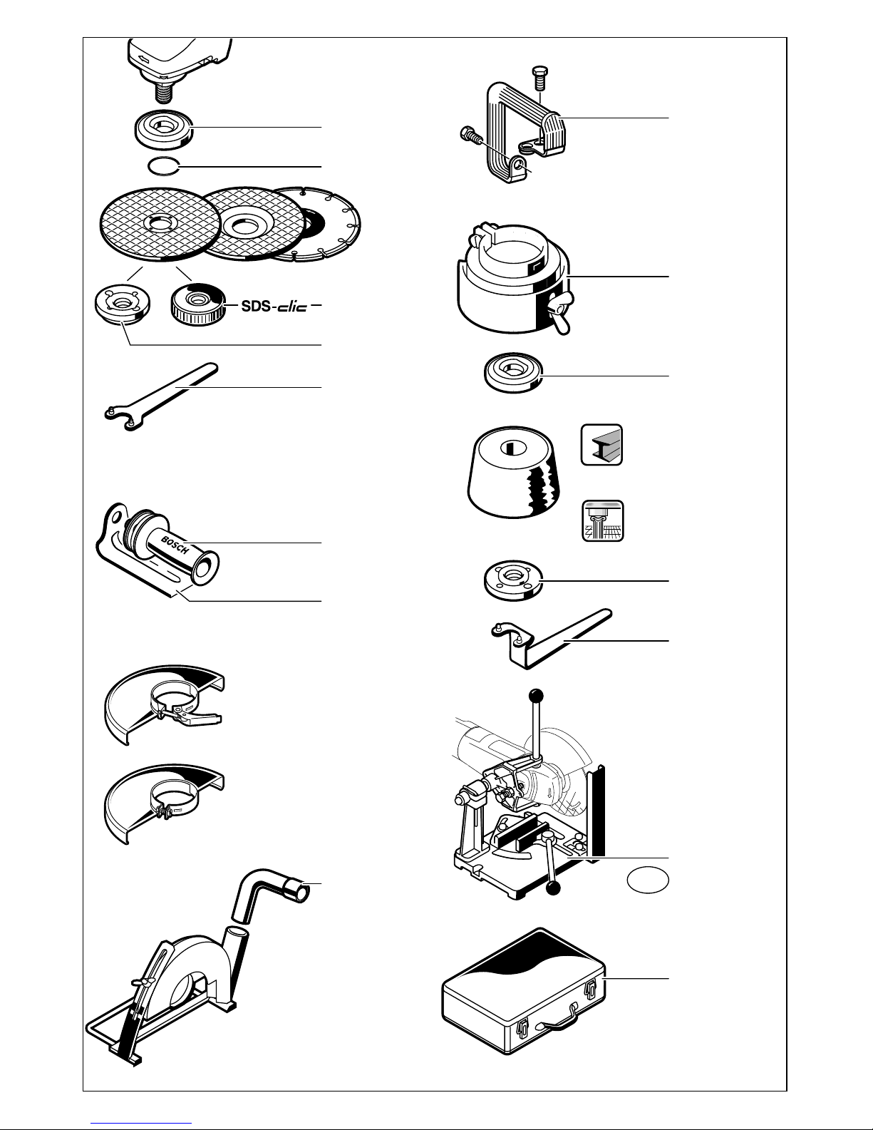
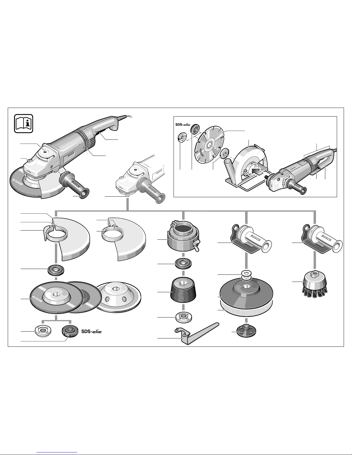
Die Nummerierung der Geräteelemente bezieht
sich auf die Darstellung des Gerätes auf der Grafikseite.
Bitte klappen Sie die Aufklappseite mit der Darstellung des Gerätes auf, und lassen Sie diese
Seite aufgeklappt, während Sie die Bedienungsanleitung lesen.
1
Gewinde Zusatzgriff (3x)
2
Spindel-Arretiertaste
3
Ein-/Ausschalter
4
Vibrationsdämpfung
5
Zusatzgriff
6
Schleifspindel
7
Schutzhaube
8
Justierschraube
9
Spannhebel
10 Aufnahmeflansch mit O-Ring
11 Schrupp-/Trennscheibe*
12 Spannmutter
13 Schnellspannmutter *
14 Klemmschraube
15 Codiernase
16 Schutzhaube Schleiftopf*
17 Schleiftopf*
18 Zweilochschlüssel für Spannmutter*
19 Handschutz*
20 Distanzscheiben*
21 Gummischleifteller*
22 Schleifblatt*
23 Rundmutter*
24 Topfbürste*
25 Diamant-Trennscheibe*
26 Führungsschlitten mit Absaugschutzhaube*
27 Griffentriegelung
28 Griff
29 Trennschleifständer*
*
Abgebildetes oder beschriebenes Zubehör gehört
teilweise nicht zum Lieferumfang.
Gefahrloses Arbeiten mit dem
Gerät ist nur möglich, wenn Sie
die Bedienungsanleitung und
die Sicherheitshinweise vollständig lesen und die darin ent-
haltenen Anweisungen strikt befolgen. Zusätzlich müssen die allgemeinen
Sicherheitshinweise im beigefügten Heft befolgt werden. Lassen Sie sich vor dem ersten
Gebrauch praktisch einweisen.
■
Schutzbrille und Gehörschutz tragen.
■
Tragen Sie zur Sicherheit auch weitere
Schutzausrüstung wie Schutzhandschuhe,
festes Schuhwerk, Helm und Schürze.
■
Beim Arbeiten entstehende Stäube können
gesundheitsschädlich, brennbar oder explosiv
sein. Geeignete Schutzmaßnahmen sind erforderlich.
Zum Beispiel: Manche Stäube gelten als
krebserregend. Geeignete Staub-/Späneabsaugung verwenden und Staubschutzmaske
tragen.
■
Leichtmetallstaub kann brennen oder explodieren. Arbeitsplatz stets sauber halten, weil
Materialmischungen besonders gefährlich
sind.
■
Wird bei der Arbeit das Netzkabel beschädigt
oder durchtrennt, Kabel nicht berühren, sondern sofort den Netzstecker ziehen. Gerät niemals mit beschädigtem Kabel benutzen.
■
Geräte, die im Freien verwendet werden, über
einen Fehlerstrom-(FI-)Schutzschalter mit maximal 30 mA Auslösestrom anschließen. Das
Gerät nicht bei Regen oder Nässe verwenden.
■
Beim Arbeiten das Gerät immer fest mit beiden
Händen halten und für einen sicheren Stand
sorgen.
■
Sichern Sie das Werkstück. Ein mit Spann-
vorrichtungen oder Schraubstock festgehaltenes Werkstück ist sicherer gehalten als mit Ihrer Hand.
■
Kabel immer nach hinten vom Gerät wegführen.
■
Das Gerät vor dem Ablegen immer ausschalten und warten bis das Gerät zum Stillstand
gekommen ist.
■
Bei Stromausfall oder wenn der Netzstecker
gezogen wird, den Ein-/Ausschalter sofort entriegeln und in Aus-Position bringen. Dies verhindert einen unkontrollierten Wiederanlauf.
■
Das Gerät darf nur für Trockenschnitt/Trockenschliff verwendet werden.
Geräteelemente
Zu Ihrer Sicherheit
7 • 1 609 929 F55 • TMS • 18.12.03

Deutsch - 3
■ Bei allen Arbeiten mit dem Gerät muss der Zu-
satzgriff
montiert sein.
■
Das Elektrowerkzeug nur an isolierten
Handgriffen anfassen, wenn das Einsatzwerkzeug eine verborgene Leitung oder
das eigene Netzkabel treffen kann.
Kontakt mit einer spannungsführenden Leitung kann Metallteile des Gerätes unter Spannung setzen und zu einem elektrischen Schlag
führen.
■
Verwenden Sie geeignete Suchgeräte, um
verborgene Versorgungsleitungen aufzuspüren, oder ziehen Sie die örtliche Versorgungsgesellschaft hinzu.
Kontakt mit Elektroleitungen kann zu Feuer
und elektrischem Schlag führen. Beschädigung einer Gasleitung kann zur Explosion
führen. Eindringen in eine Wasserleitung verursacht Sachbeschädigung oder kann einen
elektrischen Schlag verursachen.
■
Für Arbeiten mit Schrupp- oder Trennscheiben
muss die Schutzhaube
7
montiert sein. Für Ar-
beiten mit dem Gummischleifteller
21 oder mit
der Topfbürste
24 /Scheibenbürste/Fächer-
schleifscheibe ist der Handschutz
19 (Zube-
hör) zu montieren.
■
Beim Bearbeiten von Stein eine Staubabsaugung verwenden. Der Staubsauger muss zum
Absaugen von Gesteinsstaub zugelassen
sein. Zum Trennen von Stein ist ein Führungsschlitten zu verwenden.
■
Asbesthaltiges Material darf nicht bearbeitet
werden.
■
Nur Schleifwerkzeuge verwenden, deren zulässige Drehzahl mindestens so hoch ist wie
die Leerlaufdrehzahl des Gerätes.
■
Schleifwerkzeuge vor dem Gebrauch überprüfen. Das Schleifwerkzeug muss einwandfrei
montiert sein und sich frei drehen können. Probelauf mindestens 30 Sekunden ohne Belastung durchführen. Beschädigte, unrunde oder
vibrierende Schleifwerkzeuge nicht verwenden.
■
Schleifwerkzeug vor Schlag, Stoß und Fett
schützen.
■
Das Gerät nur eingeschaltet gegen das Werkstück führen.
■
Hände weg von rotierenden Schleifwerkzeugen.
■
Die Drehrichtung beachten. Gerät immer so
halten, dass Funken oder Schleifstaub vom
Körper weg fliegen.
■
Beim Schleifen von Metallen entsteht Funkenflug. Darauf achten, dass keine Personen gefährdet werden. Wegen der Brandgefahr dürfen sich keine brennbaren Materialien in der
Nähe (Funkenflugbereich) befinden.
■
Vorsicht beim Schlitzen z. B. in tragenden
Wänden: Siehe Hinweise zur Statik.
■
Blockieren der Trennscheibe führt zur ruckartigen Reaktionskraft des Gerätes. In diesem
Fall Gerät sofort ausschalten.
■
Die Abmessungen der Schleifscheiben beachten. Der Lochdurchmesser muss ohne Spiel
zum Aufnahmeflansch
10 passen. Keine Re-
duzierstücke oder Adapter verwenden.
■
Niemals Trennscheiben zum Schruppschleifen verwenden. Trennscheiben keinem seitlichen Druck aussetzen.
■
Anweisung des Herstellers zur Montage und
Verwendung des Schleifwerkzeuges beachten.
■
Vorsicht! Schleifkörper läuft nach dem Ausschalten des Gerätes noch nach.
■
Gerät nicht im Schraubstock festspannen.
■
Niemals Kindern die Benutzung des Gerätes
gestatten.
■
Bosch kann nur dann eine einwandfreie Funktion des Gerätes zusichern, wenn das für dieses Gerät vorgesehene Original-Zubehör verwendet wird.
■
Vor allen Arbeiten am Gerät Netzstecker
ziehen.
■
Für Arbeiten mit Schrupp- oder Trennscheiben muss die Schutzhaube 7 montiert
sein.
Schutzhaube mit Klemmschraube
Die Codiernase 15 an der Schutzhaube 7 stellt
sicher, dass nur eine zum Gerätetyp passende
Schutzhaube montiert werden kann.
Die Klemmschraube 14 eventuell lösen.
Die Schutzhaube 7 mit der Codiernase 15 in die
Codiernut am Spindelhals des Gerätekopfes setzen und in die erforderliche Stellung (Arbeitsposition) drehen.
Die geschlossene Seite der Schutzhaube 7
muss stets zum Bediener zeigen.
Die Klemmschraube 14 festziehen.
Schutzvorrichtungen
montieren
8 • 1 609 929 F55 • TMS • 18.12.03

Deutsch - 4
Schutzhaube mit Schnellverschluss
☞
Die Schutzhaube ist auf den Durchmesser
des Spindelhalses vorjustiert. Falls erforderlich, kann die Spannkraft des Verschlusses durch Lösen oder Anziehen der
Justierschraube 8 verändert werden. Dabei stets auf festen Sitz der Schutzhaube 7
auf dem Spindelhals achten.
Den Spannhebel 9 öffnen.
Die Schutzhaube 7 auf den Spindelhals des Ge-
rätekopfes setzen und in die erforderliche Stellung (Arbeitsposition) drehen.
Zum Festklemmen der Schutzhaube 7 den
Spannhebel 9 schließen.
Die geschlossene Seite der Schutzhaube 7
muss stets zum Bediener zeigen.
Zusatzgriff
■ Bei allen Arbeiten mit dem Gerät muss der
Zusatzgriff montiert sein.
Den Zusatzgriff 5 abhängig von der Arbeitsweise
am Gerätekopf einschrauben.
Vibrationsdämpfung
Die integrierte Vibrationsdämpfung 4 und der vibrationsdämpfende Zusatzgriff reduzieren auftretende Vibrationen gemäß EN 50 144 auf unter
2,5 m/s
2
und ermöglichen ein vibrationsarmes
und damit ein angenehmeres und sicheres Arbeiten.
Keinerlei Veränderungen an der Vibrationsdämpfung 4 und dem Zusatzgriff
vornehmen. Beschädigte Teile nicht
weiter verwenden.
Handschutz
Für Arbeiten mit dem Gummischleifteller 21 oder
mit der Topfbürste 24/Scheibenbürste/Fächer-
schleifscheibe ist der Handschutz 19 (Zubehör)
zu montieren. Der Handschutz 19 wird mit dem
Zusatzgriff 5 befestigt.
■ Vor allen Arbeiten am Gerät Netzstecker
ziehen.
Nur Schleifwerkzeuge verwenden, deren zulässige Drehzahl mindestens so
hoch ist wie die Leerlaufdrehzahl des
Gerätes.
Schrupp- und Trennscheiben werden
beim Arbeiten sehr heiß; nicht anfassen
bevor sie abgekühlt sind.
■ Die Schleifspindel und alle zu montierenden
Teile reinigen. Zum Festspannen und Lösen
der Schleifwerkzeuge die Schleifspindel 6
feststellen mit der Spindel-Arretiertaste 2.
Die Spindel-Arretiertaste 2 nur bei stillstehender Schleifspindel betätigen!
Schrupp-/Trennscheibe
Die Abmessungen der Schleifscheiben beachten. Der Lochdurchmesser muss ohne Spiel zum
Aufnahmeflansch 10 passen. Keine Reduzierstücke oder Adapter verwenden.
Bei Verwendung einer Diamant-Trennscheibe
darauf achten, dass der Drehrichtungspfeil auf
der Diamant-Trennscheibe und die Drehrichtung
des Gerätes (Drehrichtungspfeil auf dem Gerätekopf) übereinstimmen.
Montage siehe Bildseite.
Die Spannmutter 12 aufschrauben und mit dem
Zweilochschlüssel festziehen (siehe Abschnitt
„Schnellspannmutter“).
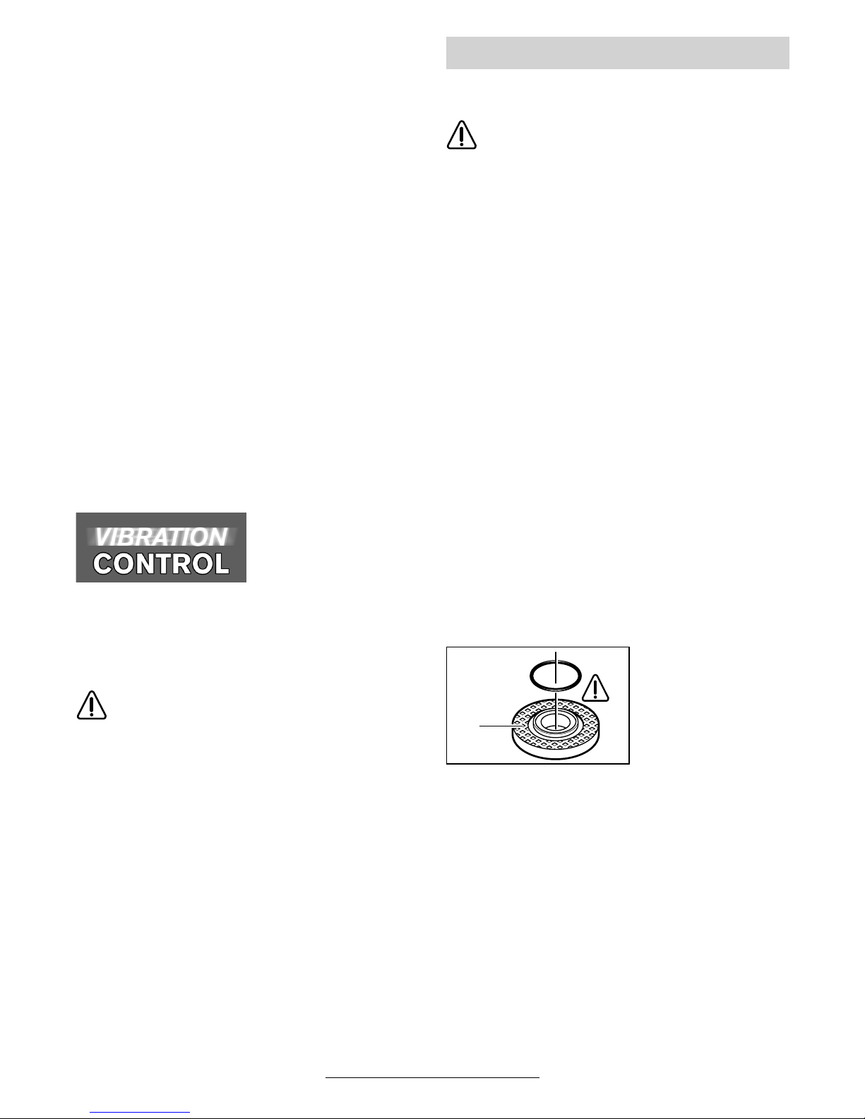
Im Aufnahmeflansch 10 ist um den
Zentrierbund ein ORing (Kunststoffteil)
eingesetzt.
Fehlt der O-Ring oder ist er beschädigt, muss
er unbedingt ersetzt werden (Bestell-Nr.
1 600 210 039), bevor der Aufnahmeflansch 10
montiert wird.
☞
Nach der Montage des Schleifwerkzeuges vor dem Einschalten prüfen, ob das
Schleifwerkzeug richtig montiert ist und
sich frei drehen kann.
Schleifwerkzeuge montieren
10
9 • 1 609 929 F55 • TMS • 18.12.03
Deutsch - 5
Fächerschleifscheibe
(Schleifmopteller)
Je nach Anwendung ggf. die Schutzhaube 7 abnehmen und den Handschutz 19 montieren.
Speziellen Aufnahmeflansch 10 (Zubehör, Bestell-Nr. 2 605 703 028) und die Fächerschleifscheibe auf die Schleifspindel 6 setzen. Die
Spannmutter 12 aufschrauben und mit dem
Zweilochschlüssel festziehen.
Gummi-Schleifteller 21
Je nach Anwendung ggf. die Schutzhaube 7 abnehmen und den Handschutz 19 montieren.
Bevor der Gummischleifteller 21 montiert wird,
zuerst die 2 Distanzscheiben 20 auf die Schleifspindel setzen.
Montage siehe Bildseite.
Die Rundmutter 23 aufschrauben und mit dem
Zweilochschlüssel festziehen.
Topfbürste 24/Scheibenbürste
Je nach Anwendung ggf. die Schutzhaube 7 abnehmen und den Handschutz 19 montieren.
Das Schleifwerkzeug muss sich so weit auf die
Schleifspindel 6 aufschrauben lassen, dass es
am Schleifspindelflansch am Ende des Schleifspindelgewindes fest anliegt. Mit Gabelschlüssel
festziehen.
Schleiftopf
Beim Arbeiten mit Schleiftöpfen spezielle Schutzhaube 16 verwenden.
Der Schleiftopf 17 sollte immer nur soweit aus
der Schutzhaube 16 ragen, wie dies für den jeweiligen Bearbeitungsfall unbedingt erforderlich
ist.
Die Schutzhaube 16 auf dieses Maß nachstellen.
Montage siehe Bildseite.
Die Spannmutter 12 aufschrauben und mit passendem gekröpftem Zweilochschlüssel 18 festziehen.
Anstelle der Spannmutter 12 kann die Schnellspannmutter 13 (Zubehör) verwendet werden.
Schleifwerkzeuge lassen sich dann ohne Werkzeug montieren.
Die Schnellspannmutter 13 darf nur für
Schrupp- und Trennscheiben verwendet werden.
Nur einwandfreie, unbeschädigte Schnellspannmutter 13 verwenden.
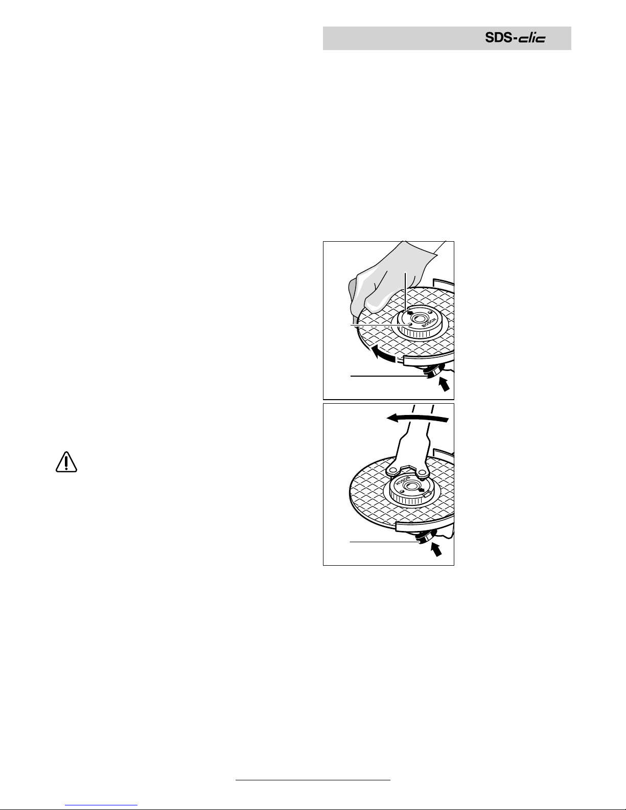
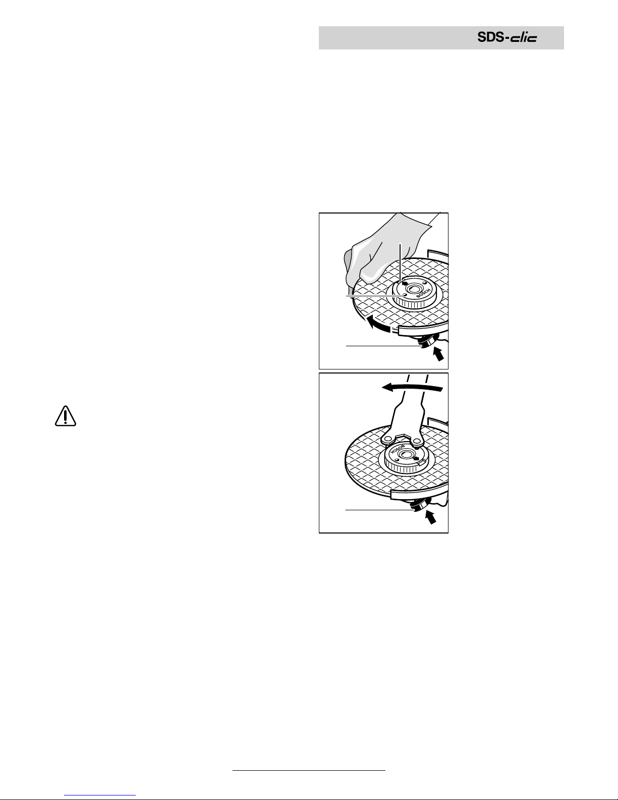
Beim Aufschrauben darauf achten, dass die
beschriftete Seite nicht zur Schleifscheibe
zeigt; der Pfeil muss auf die Indexmarke 30
zeigen.
Die Schleifspindel
feststellen mit der
Spindel-Arretiertaste 2. Die Schnellspannmutter durch
kräftiges Drehen der
Schleifscheibe im
Uhrzeigersinn festziehen.
Eine ordnungsgemäß befestigte unbeschädigte Schnellspannmutter lässt
sich durch Drehen
des Rändelringes
entgegen dem Uhrzeigersinn von Hand
lösen.
Eine festsitzende
Schnellspannmutter nie mit einer
Zange lösen, sondern Zweilochschlüssel verwenden. Den Zweiloch-
schlüssel wie im Bild
gezeigt ansetzen.
Schnellspannmutter
2
30
13
2
10 • 1 609 929 F55 • TMS • 18.12.03
Deutsch - 6
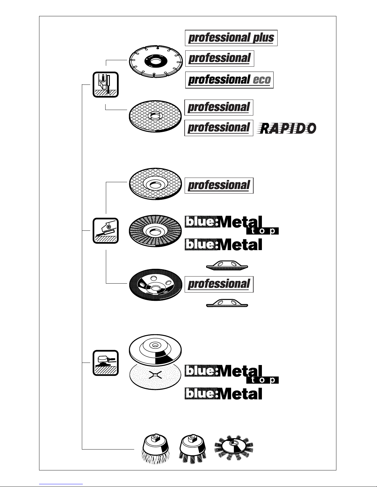
Verwendet werden können alle in dieser Bedienungsanleitung genannten Schleifwerkzeuge.
Die zulässige Drehzahl [min
-1
] bzw. Umfangsgeschwindigkeit [m/s] der verwendeten Schleifwerkzeuge muss den Angaben in der Tabelle
mindestens entsprechen.
Deshalb stets die zulässige Drehzahl/Um-
fangsgeschwindigkeit auf dem Etikett der
Schleifwerkzeuge beachten.
Netzspannung beachten: Die Spannung der
Stromquelle muss mit den Angaben auf dem
Typschild des Gerätes übereinstimmen. Mit
230 V gekennzeichnete Geräte können auch an
220 V betrieben werden.
Ein-/Ausschalten
Zur Inbetriebnahme des Gerätes den Ein-/Ausschalter 3 nach vorn schieben und anschließend
drücken.
Zum Feststellen den Ein-/Ausschalter 3 in gedrücktem Zustand weiter vorschieben.
Zum Ausschalten des Gerätes den Ein-/Ausschalter 3 loslassen bzw. drücken und loslassen.
Schalterausführung ohne Arretierung
(länderspezifisch):
Zur Inbetriebnahme des Gerätes den Ein-/Ausschalter 3 nach vorn schieben und anschließend
drücken.
Zum Ausschalten des Gerätes den Ein-/Ausschalter 3 loslassen.
☞
Probelauf!
Schleifwerkzeuge vor Gebrauch überprüfen. Das Schleifwerkzeug muss einwandfrei montiert sein und sich frei drehen können. Probelauf mindestens 30 Sekunden
ohne Belastung durchführen. Beschädigte,
unrunde oder vibrierende Schleifwerkzeuge nicht verwenden.
Anlaufstrombegrenzung (Typ J)
Durch sanften Anlauf des Gerätes reicht
eine 16-A-Sicherung aus.
Ein Gerät ohne Anlaufstrombegrenzung
benötigt eine höhere Absicherung (mind.
eine träge 16-A-Sicherung einsetzen).
■ Das Werkstück einspannen, sofern es
nicht durch sein Eigengewicht sicher liegt.
■ Das Gerät nicht so stark belasten, dass es
zum Stillstand kommt.
■ Schrupp- und Trennscheiben werden beim
Arbeiten sehr heiß; nicht anfassen bevor
sie abgekühlt sind.
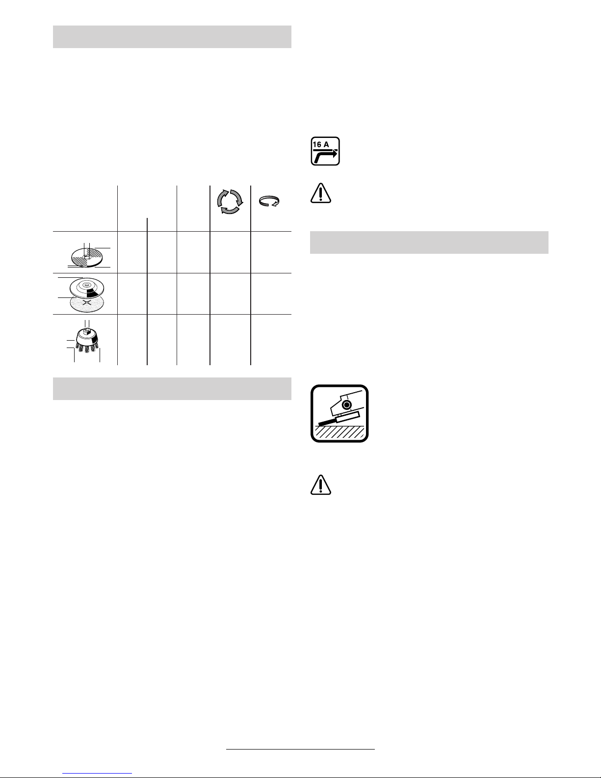
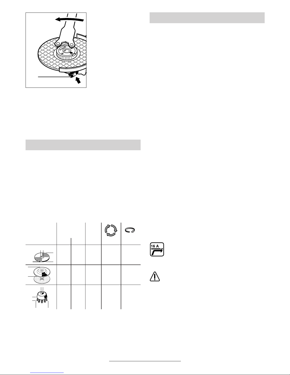
Schruppschleifen
Mit Anstellwinkeln von 30° bis 40°
erreicht man beim Schruppen das
beste Ergebnis. Gerät mit mäßigem Druck hin und her bewegen.
Dadurch wird das Werkstück nicht
zu heiß, verfärbt sich nicht, und es
gibt keine Rillen.
Niemals Trennscheiben zum Schruppen
verwenden.
Fächerschleifscheibe
(Schleifmopteller)
Mit der Fächerschleifscheibe (Zubehör) lassen
sich auch gewölbte Oberflächen und Profile
(Konturenschliff) bearbeiten.
Fächerschleifscheiben haben wesentlich höhere
Standzeiten als Schleifblätter, geringere Geräuschpegel und niedrigere Schleiftemperaturen.
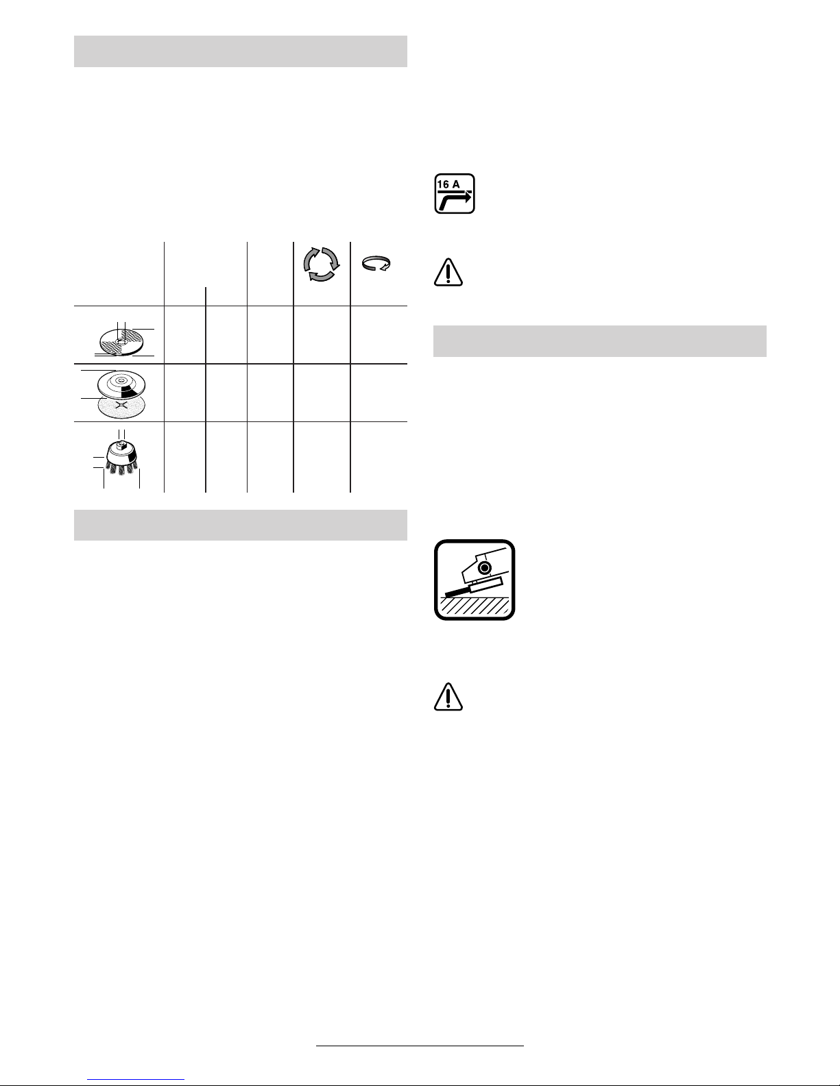
Zulässige Schleifwerkzeuge
max.
[mm] [mm]
Db d[min
-1
] [m/s]
180
23088
22,2
22,2
8 500
6 500
80
80
180
230––
–
–
8 500
6 500
80
80
100 30 M 14 8 500 45
Inbetriebnahme
b
d
D
D
D
b
d
Arbeitshinweise
11 • 1 609 929 F55 • TMS • 18.12.03
Deutsch - 7
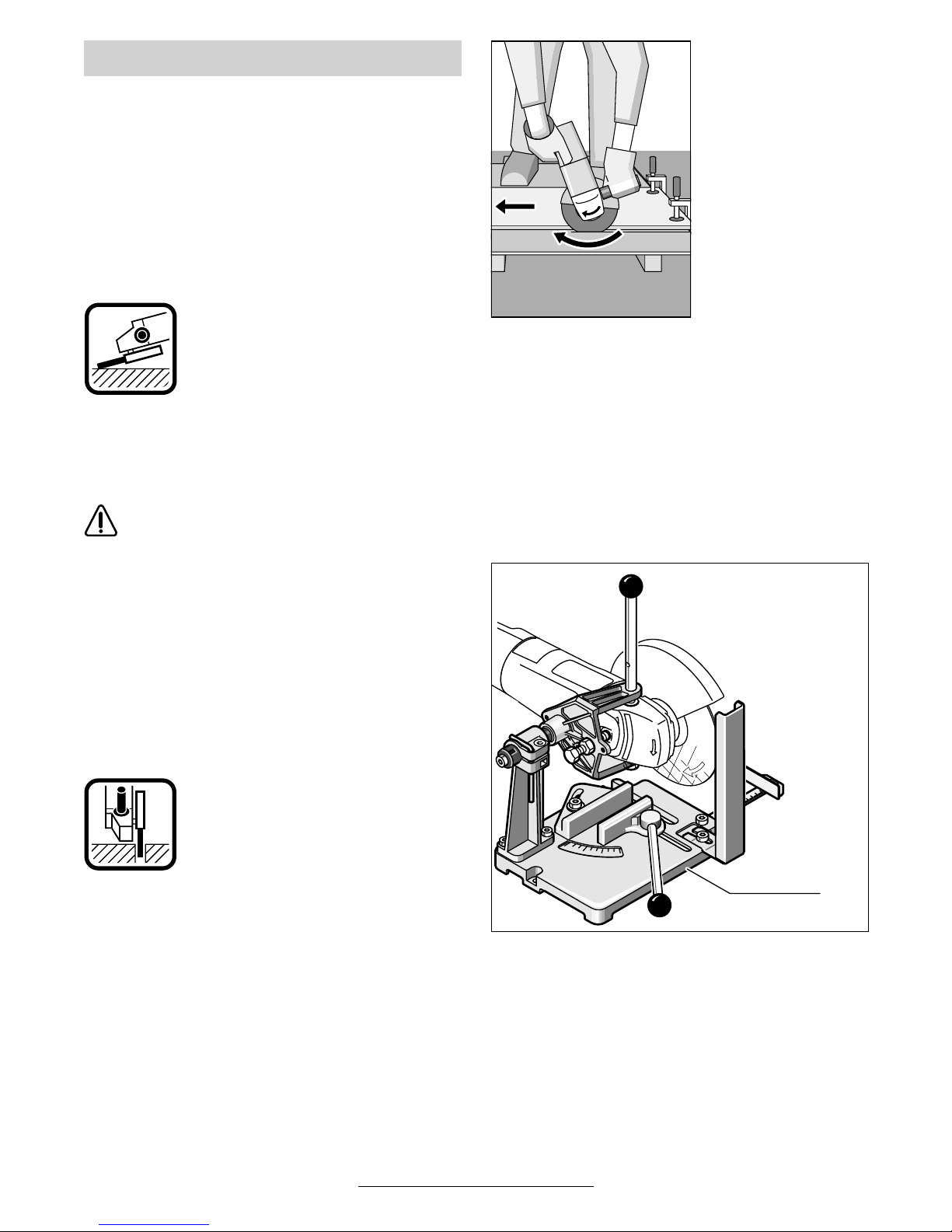
Trennschleifen
Beim Trennschleifen nicht drücken,
nicht verkanten, nicht oszillieren.
Mit mäßigem, dem zu bearbeitenden Material angepassten Vorschub arbeiten.
Auslaufende Trennschleifscheiben
nicht durch seitliches Gegendrü-
cken abbremsen.
Wichtig ist die Richtung, in die man
trennt.
Das Gerät muss
stets im Gegenlauf
arbeiten; deshalb mit
dem Gerät nicht in
die andere Richtung
fahren! Es besteht
sonst die Gefahr,
dass es unkontrol-
liert aus dem Schnitt
gedrückt wird.
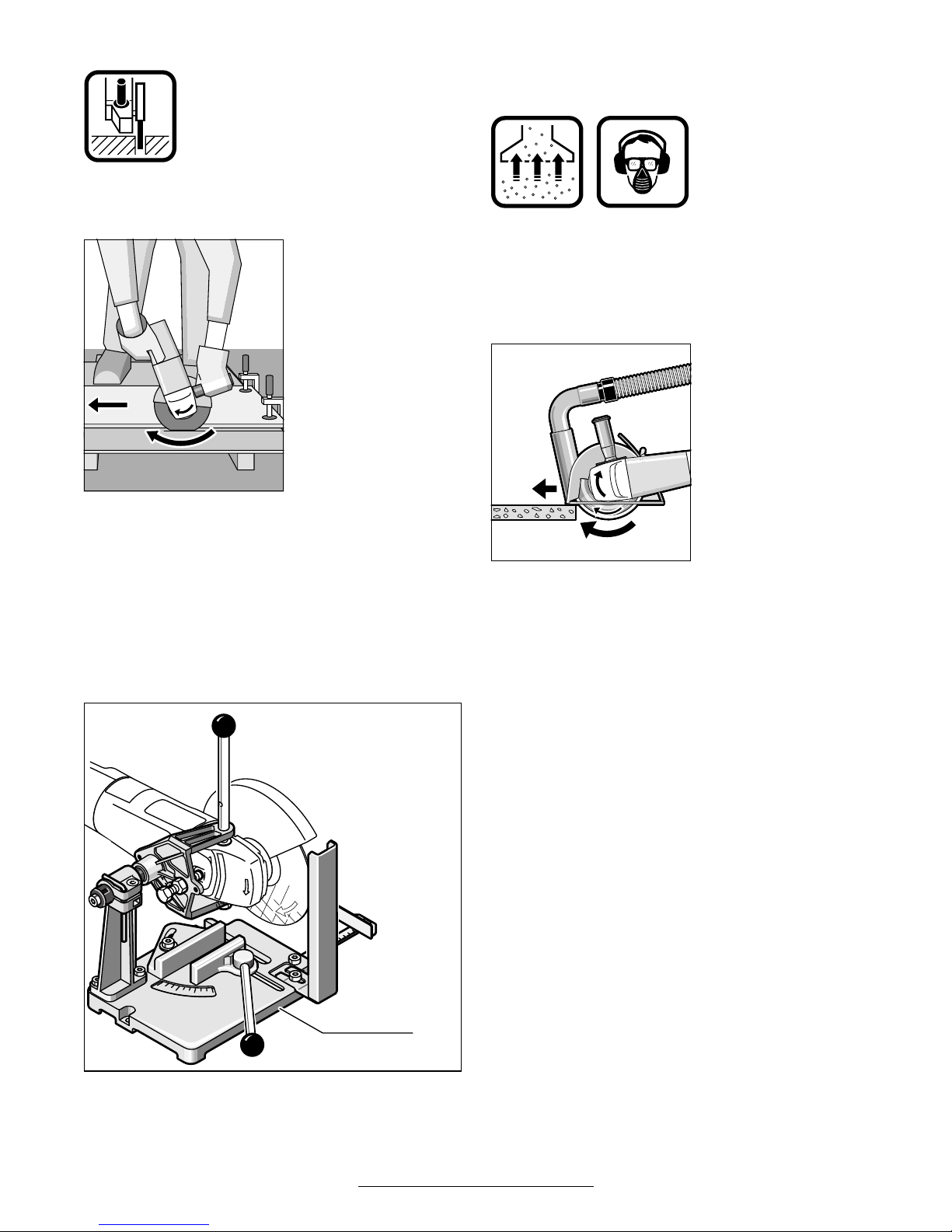
Trennschleifständer
Mit dem Trennschleifständer 29 (Zubehör) kön-
nen Werkstücke längengleich im Winkel von
0 bis 45° zugeschnitten werden.
Die Sicherheits- und Arbeitshinweise in der entsprechenden Bedienungsanleitung des Trennschleifständers sind strikt zu beachten. Nur Original Bosch Trennschleifständer verwenden.
Trennen von Gestein
■ Das Gerät darf nur für Trockenschnitt/Trockenschliff verwendet werden.
Am besten eine Diamant-Trennscheibe
verwenden. Zur Sicherheit gegen Verkanten den Füh-
rungsschlitten 26
mit spezieller Absaugschutzhaube
benutzen.
Das Gerät nur mit Staubabsaugung betreiben.
Zusätzlich Staubschutzmaske tragen.
Der Staubsauger
muss zum Absaugen
von Gesteinsstaub
zugelassen sein.
Bosch bietet geeignete Staubsauger an.
Das Gerät einschalten
und mit dem vorderen
Teil des Führungsschlittens auf das
Werkstück setzen.
Das Gerät mit mäßigem, dem zu bearbeitenden
Material angepassten Vorschub schieben (Bild).
Beim Trennen besonders harter Werkstoffe, z. B.
Beton mit hohem Kieselgehalt, kann die Diamant-Trennscheibe überhitzen und dadurch beschädigt werden. Ein mit der Diamant-Trennscheibe umlaufender Funkenkranz weist deutlich
darauf hin.
In diesem Fall den Trennvorgang unterbrechen
und die Diamant-Trennscheibe kurze Zeit unbelastet bei Leerlaufdrehzahl abkühlen lassen.
Merklich nachlassender Arbeitsfortschritt und
umlaufender Funkenkranz sind Anzeichen für
eine stumpf gewordene Diamant-Trennscheibe.
Durch kurze Schnitte in abrasivem Material (z. B.
Kalksandstein) kann diese wieder geschärft werden.
29
12 • 1 609 929 F55 • TMS • 18.12.03
Deutsch - 8
■ Vor allen Arbeiten am Gerät Netzstecker
ziehen.
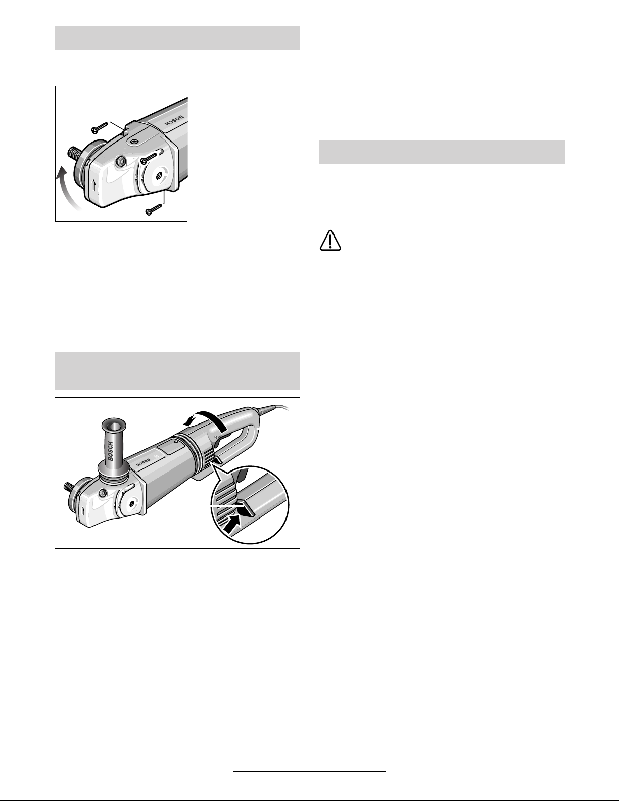
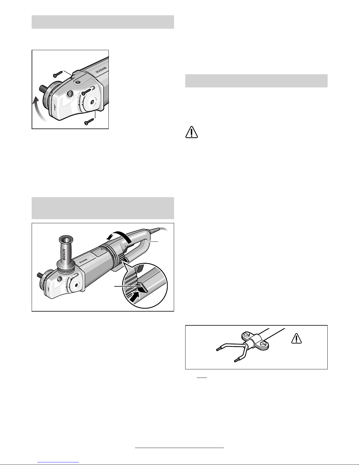
Der Gerätekopf lässt
sich zum Gerätege-
häuse in 90°-Schritten drehen. Dadurch
kann der Ein-/Ausschalter für besondere Arbeitsfälle in
eine günstigere
Handhabungsposition gebracht werden; z. B. für Trennarbeiten mit Füh-
rungsschlitten 26/Trennschleifständer 29
(Zubehör) oder für Linkshänder.
Die vier Schrauben ganz herausdrehen.
Den Gerätekopf vorsichtig und ohne vom Ge-
häuse abzunehmen in die neue Position drehen.
Die Schrauben wieder eindrehen und festziehen.
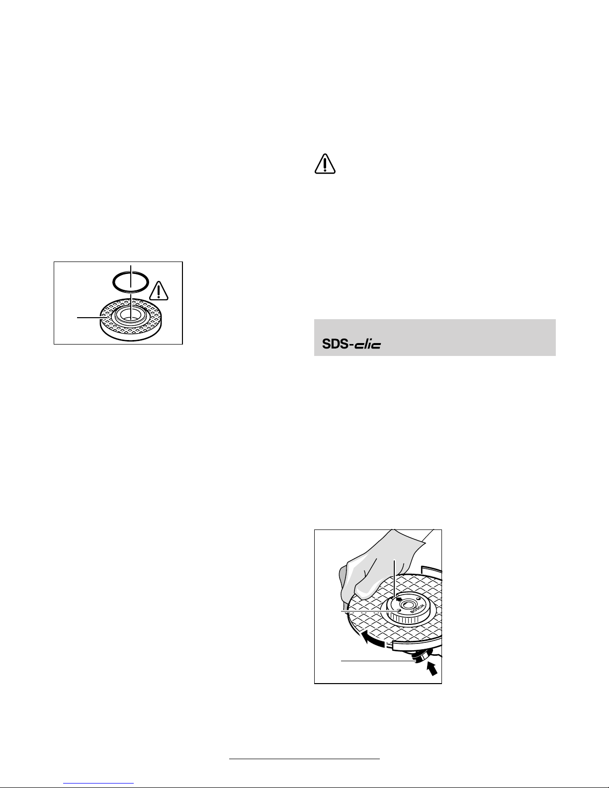
Der Griff 28 lässt sich zum Motorgehäuse jeweils
um 90° nach links und nach rechts drehen. Dadurch kann der Ein-/Ausschalter für besondere
Arbeitsfälle in eine günstigere Handhabungsposition gebracht werden; z. B. für Trennarbeiten
mit Führungsschlitten/Trennschleifständer (Zubehör) und für Linkshänder.
Die Griffentriegelung 27 kräftig in Pfeilrichtung
ziehen (
➊) und gleichzeitig den Griff 28 in die ge-
wünschte Position drehen (
➋) bis er einrastet.
Die Abbildung zeigt den Griff 28 um 90° gedreht.
☞
Die Griffentriegelung 27 und der Ein-/Ausschalter 3 haben eine Sicherheitsverriegelung.
Das Gerät kann nicht eingeschaltet werden, solange der Griff 28 nicht in einer der
drei möglichen Positionen eingerastet ist.
Der Griff 28 lässt sich nicht entriegeln,
wenn der Ein-/Ausschalter 3 arretiert ist.
■ Vor allen Arbeiten am Gerät Netzstecker
ziehen.
☞
Gerät und Lüftungsschlitze stets sauber
halten, um gut und sicher zu arbeiten.
Bei extremen Einsatzbedingungen kann
sich bei der Bearbeitung von Metallen leitfähiger Staub im Innern des Gerätes absetzen. Die Schutzisolierung des Gerätes
kann beeinträchtigt werden. Es empfiehlt
sich in solchen Fällen die Verwendung einer stationären Absauganlage, häufiges
Ausblasen der Lüftungsschlitze und das
Vorschalten eines Fehlerstrom-Schutzschalters (FI).
Wenn die schwingungsdämpfenden Elemente an
der Vibrationsdämpfung 4 beschädigt sind, z. B.
eingerissen, muss das Gerät zur Wartung an den
Kundendienst geschickt werden (Anschrift siehe
Abschnitt „Service und Kundenberater“).
Sollte das Gerät trotz sorgfältiger Herstellungsund Prüfverfahren einmal ausfallen, ist die Reparatur von einer autorisierten Kundendienststelle
für Bosch-Elektrowerkzeuge ausführen zu lassen.
Bei allen Rückfragen und Ersatzteilbestellungen
bitte unbedingt die 10-stellige Bestellnummer laut
Typenschild des Gerätes angeben.
Gerätekopf drehen
Gerätegriff drehen
(GWS 24/26-180/230 (J)BV)
27
➊
➋
28
Wartung und Reinigung
13 • 1 609 929 F55 • TMS • 18.12.03

Deutsch - 9
Rohstoffrückgewinnung statt Müllentsorgung
Gerät, Zubehör und Verpackung sollten einer
umweltgerechten Wiederverwertung zugeführt
werden.
Diese Anleitung ist aus chlorfrei gefertigtem Recycling-Papier hergestellt.
Zum sortenreinen Recycling sind Kunststoffteile
gekennzeichnet.
In Deutschland sind nicht mehr gebrauchsfähige
Geräte zum Recycling beim Handel abzugeben
oder (ausreichend frankiert) direkt einzuschicken
an:
Recyclingzentrum Elektrowerkzeuge
Osteroder Landstraße 3
37589 Kalefeld
Explosionszeichnungen und Informationen
zu Ersatzteilen finden Sie unter:
www.bosch-pt.com
www.powertool-portal.de, das Internetportal
für Handwerker und Heimwerker
www.ewbc.de, der Informations-Pool für Hand-
werk und Ausbildung
Deutschland
Robert Bosch GmbH
Servicezentrum Elektrowerkzeuge
Zur Luhne 2
37589 Kalefeld
✆ Service: ....................................... 01 80 - 3 35 54 99
Fax:
........................................... +49 (0) 55 53 / 20 22 37
✆ Kundenberater: ...................... 01 80 - 3 33 57 99
Österreich
ABE Service GmbH
Jochen-Rindt-Straße 1
1232 Wien
✆ Service: ..................................... +43 (0)1 / 61 03 80
Fax:
............................................... +43 (0)1 / 61 03 84 91
✆ Kundenberater:............ +43 (0)1 / 797 22 3066
E-Mail: abe@abe-service.co.at
Schweiz
✆ Service: ................................. +41 (0)1 / 8 47 16 16
Fax:
.................................................. +41 (0)1 / 8 47 16 57
✆ Kundenberater............................... 0 800 55 11 55
Wir erklären in alleiniger Verantwortung, dass
dieses Produkt mit den folgenden Normen oder
normativen Dokumenten übereinstimmt:
EN 50 144 gemäß den Bestimmungen der Richtlinien 89/336/EWG, 98/37/EG.
Dr. Egbert Schneider Dr. Eckerhard Strötgen
Senior Vice President Head of Product
Engineering Certification
Robert Bosch GmbH, Geschäftsbereich Elektrowerkzeuge
Änderungen vorbehalten
Umweltschutz Service und Kundenberater
Konformitätserklärung
14 • 1 609 929 F55 • TMS • 18.12.03

English - 1
The machine is intended for cutting, roughing and
brushing metal and stone materials without using
water. For cutting stone, a cutting guide is required.
Slots in structural walls are subject to the Standard DIN 1053, Part 1 or country-specific regulations.
These regulations are to be observed under all
circumstances. Before beginning work, consult
the responsible structural engineer, architects or
the construction supervisor.
Measured values determined according to
EN 50 144.
Typically the A-weighted noise levels of the machine are: Sound pressure level: 90 dB (A);
sound power level: 103 dB (A).
Wear hearing protection!
The typical hand/arm vibration is below 2.5 m/s
2
(1.7 m/s2).
Tool Specifications
Angle Grinder GWS 21-180 HV
PROFESSIONAL
GWS 21-230 HV
PROFESSIONAL
GWS 24-180 BV
PROFESSIONAL
Order number 0 601 851 B.. 0 601 852 B.. 0 601 853 B..
With residual current-limit control GWS 21-180 JHV
PROFESSIONAL
GWS 21-230 JHV
PROFESSIONAL
GWS 24-180 JBV
PROFESSIONAL
Order number 0 601 851 G.. 0 601 852 G.. 0 601 853 G..
Rated input power* [W] 2 100 2 100 2 400
Output power [W] 1 350 1 350 1 700
No-load speed [rpm] 8 500 6 500 8 500
Grinding disc dia., max. [mm] 180 230 180
Grinder spindle thread M 14 M 14 M 14
Weight without cable, approx. [kg] 4.4 4.4 5.2
Protection class / II / II / II
Angle Grinder GWS 24-230 BV
PROFESSIONAL
GWS 26-180 BV
PROFESSIONAL
GWS 26-230 BV
PROFESSIONAL
Order number 0 601 854 B.. 0 601 855 B.. 0 601 856 B..
With residual current-limit control GWS 24-230 JBV
PROFESSIONAL
GWS 26-180 JBV
PROFESSIONAL
GWS 26-230 JBV
PROFESSIONAL
Order number 0 601 854 G.. 0 601 855 G.. 0 601 856 G..
Rated input power* [W] 2 400 2 600 2 600
Output power [W] 1 700 1 800 1 800
No-load speed [rpm] 6 500 8 500 6 500
Grinding disc dia., max. [mm] 230 180 230
Grinder spindle thread M 14 M 14 M 14
Weight without cable, approx. [kg] 5.2 5.2 5.2
Protection class / II / II / II
Please observe the order number of your machine. The trade names of the individual machines may vary.
Inrush currents cause short-time voltage drops. Under unfavourable power supply conditions, other equipment may be
affected. If the system impedance of the power supply is lower than 0.25 Ohm, disturbances are unlikely to occur.
* The values given are valid for nominal voltages [U] of 230/240 V. For lower voltages and models for specific countries,
these values can vary.
Intended Use
Information on Structures
Noise/Vibration Information
15 • 1 609 929 F55 • TMS • 18.12.03
English - 2
The numbering of the device elements refers to
the illustration of the machine on the graphics
page.
While reading the operating instructions, unfold
the graphics page for the device and leave it
open.
1 Thread for auxiliary handle (3x)
2 Spindle lock button
3 On/Off switch
4 Vibration damper
5 Auxiliary handle
6 Grinder spindle
7 Protection guard
8 Adjustment screw
9 Clamping lever
10 Mounting flange with O-ring
11 Grinding/cutting disc*
12 Clamping nut
13 quick-clamping nut*
14 Clamping screw
15 Coded projection
16 Guard, grinding cup*
17 Grinding cup*
18 Two-pin spanner for clamping nut*
19 Hand guard*
20 Spacer discs*
21 Rubber sanding plate*
22 Sanding sheet*
23 Round nut*
24 Cup brush*
25 Diamond cutting disc*
26 Cutting guide with dust extraction protection
guard*
27 Handle unlocking button
28 Handle
29 Cutting grinder stand*
* Not all of the accessories illustrated or described are
included as standard delivery.
Working safely with this machine is possible only when the
operating and safety information
are read completely and the instructions contained therein are
strictly followed. In addition, the
general safety notes in the enclosed booklet
must be observed. Before using for the first
time, ask for a practical demonstration.
■ Wear protective glasses and hearing protec-
tion.
■ Wear additional protection equipment for your
safety, such as protective gloves, sturdy
shoes, hard hat and apron.
■ The dust that is produced while working can be
detrimental to health, inflammable or explosive. Suitable safety measures are required.
Examples: Some dusts are regarded as carcinogenic. Use suitable dust/chip extraction and
wear a dust respirator.
■ Dust from light alloys can burn or explode. Al-
ways keep the workplace clean, as blends of
materials are particularly dangerous.
■ If the mains cable is damaged or cut through
while working, do not touch the cable but immediately pull the mains plug. Never use the
machine with a damaged cable.
■ Connect machines that are used in the open
via a residual current device (RCD) with an actuating current of 30 mA maximum. Do not operate the machine in rain or moisture.
■ When working with the machine, always hold it
firmly with both hands and provide for a secure
stance.
■ Secure the workpiece. A workpiece clamped
with clamping devices or in a vice is held more
secure than by hand.
■ Always direct the cable to the rear away from
the machine.
■ Always switch the machine off and wait until it
has come to a standstill before placing it down.
■ For power outage or when the mains plug is
pulled, unlock the On/Off switch immediately
and turn it to the off position. This prevents uncontrolled restarting.
■ The machine must be used only for dry cutting/
grinding.
Machine Elements
For Your Safety
16 • 1 609 929 F55 • TMS • 18.12.03

English - 3
■ For all work with the machine, the auxiliary
handle must be mounted.
■ Hold the power tool only by the insulated
gripping surfaces, when performing an operation where the cutting tool may run into
hidden wiring or its own cord.
Contact with a “live” wire will make exposed
metal parts of the tool “live” and shock the operator.
■ Use appropriate detectors to determine if
utility lines are hidden in the work area or
call the local utility company for assistance.
Contact with electric lines can lead to fire and
electric shock. Damaging a gas line can lead
to explosion. Penetrating a water line causes
property damage or may cause an electric
shock.
■ For work with grinding or cutting discs, the protection guard 7 must be mounted. For work
with the rubber sanding plate 21 or with the
cup brush 24/disc brush/flap disc, the hand
guard 19 (accessory) is to be mounted.
■ Use dust extraction when working with stone.
The vacuum cleaner must be approved for masonry dust. When cutting stone, use the cutting
guide.
■ Do not work with materials containing asbestos.
■ Use only grinding tools with a permissible
speed at least as high as the no-load speed of
the machine.
■ Check grinding tools before use. The grinding
tool must be properly mounted and turn freely.
Perform a test run for at least 30 seconds without load. Do not use damaged, out-of-round or
vibrating grinding tools.
■ Protect the grinding tool from impact, shock
and grease.
■ Apply the machine to the workpiece only when
switched on.
■ Keep hands away from rotating grinding tools.
■ Pay attention to the direction of rotation. Al-
ways hold the machine so that sparks and
grinding dust fly away from the body.
■ When grinding metal, flying sparks are produced. Take care that no persons are endangered. Due to danger of fire, no combustible
materials should be located in the vicinity
(spark flight zone).
■ Be careful when cutting grooves, e. g. in structural walls: See Information on Structures.
■ Blocking the cutting disc leads to jerking reaction forces on the machine. In this case switch
off the machine immediately.
■ Pay attention to the dimensions of the grinding
disc. The mounting hole diameter must fit the
mounting flange 10 without play. Do not use
reducers or adapters.
■ Never use cutting discs for rough grinding. Do
not exert any lateral pressure on the cutting
discs.
■ Observe the manufacturer’s instructions for
mounting and using grinding tools.
■ Caution! The grinding tool runs on after the
machine is switched off.
■ Do not clamp the machine in a vice.
■ Never allow children to use the machine.
■ Bosch is only able to ensure perfect operation
of the machine if the original accessories intended for it are used.
■ Before any work on the machine itself, pull
the mains plug.
■ For work with grinding or cutting discs, the
protection guard 7 must be mounted.
Protection Guard with Locking Screw
The coded projection 15 on the protection
guard 7 ensures that only a guard that fits the
machine type can be mounted.
Loosen the clamping screw 14, if necessary.
Place the protection guard 7 with coded projec-
tion 15 into the coded groove on the spindle collar of the machine head and rotate to the required
position (working position).
The closed side of the protection guard 7
must always point to the operator.
Tighten clamping screw 14.
Mounting the
Protective Devices
17 • 1 609 929 F55 • TMS • 18.12.03
English - 4
Protection Guard with Quick Clamp
☞
The protection guard is preadjusted to the
diameter of the spindle collar. If required,
the tightening tension of the clamping
bracket can be changed by tightening or
loosening the adjustment screw 8. Always
ensure that the protection guard 7 is
seated tightly on the spindle collar.
Open the clamping lever 9.
Place the protection guard 7 on the spindle collar
of the machine head and turn to the required position (working position).
To fasten the protection guard 7, close the
clamping lever 9.
The closed side of the protection guard 7
must always point to the operator.
Auxiliary Handle
■ For all work with the machine, the auxiliary
handle must be mounted.
Screw the auxiliary handle 5 into the head of the
machine according to the working method.
Vibration Damping
The integrated vibration damper 4 and the vibration-dampening auxiliary handle reduce occurring vibrations to below 2.5 m/s
2
according to
EN 50 144, and enable vibrational-reduced and
thus more agreeable and secure working.
Do not make any alterations to the vibration damper 4 and the auxiliary handle. Do not continue to use damaged
parts.
Hand Guard
For work with the rubber sanding plate 21 or with
the cup brush 24/disc brush/flap disc, the hand
guard 19 (accessory) is to be mounted. The hand
guard 19 is fastened with the auxiliary handle 5.
■ Before any work on the machine itself, pull
the mains plug.
Use only grinding tools with a permissible speed at least as high as the no-load
speed of the machine.
Grinding and cutting discs become very
hot while working; do not touch until
they have cooled.
■ Clean the grinder spindle and all parts to be
mounted. For clamping and loosening the
grinding tools, lock the grinder spindle 6 with
the spindle lock button 2.
Actuate the spindle lock button 2 only when
the grinder spindle is at a standstill!
Grinding/Cutting Disc
Pay attention to the dimensions of the grinding
disc. The mounting hole diameter must fit the
mounting flange 10 without play. Do not use reducers or adapters.
When using a diamond cutting disc, take care
that the direction-of-rotation arrow on the diamond cutting disc and the direction of rotation of
the machine (direction-of-rotation arrow on the
machine head) agree.
For mounting, see the illustration page.
Screw on the clamping nut 12 and tighten with
the two-pin spanner (see Section “Quick-clamp-
ing Nut”).
An O-ring (plastic
part) is inserted in
the mounting
flange 10 around the
spigot.
If the O-ring is missing or is damaged, it must
in all cases be replaced (Order No.
1 600 210 039) before the mounting flange 10 is
mounted.
☞
After mounting the grinding tool and before switching on, check that the grinding tool is correctly mounted and that it
can turn freely.
Mounting the Grinding Tools
10
18 • 1 609 929 F55 • TMS • 18.12.03
English - 5
Flap Disc
Depending on the application, remove the protection guard 7 and mount the hand guard 19. Place
the special mounting flange 10 (accessory, Order
No. 2 605 703 028) and the flap disc on the
grinder spindle 6. Screw on the clamping nut 12
and tighten with the two-pin spanner.
Rubber Sanding Plate 21
Depending on the application, remove the protection guard 7 and mount the hand guard 19.
Before mounting the rubber sanding pad 21,
place the 2 spacers 20 onto the grinding spindle.
For mounting, see the illustration page.
Screw on the round nut 23 and tighten with the
two-pin spanner.
Cup Brush 24/Disc Brush
Depending on the application, remove the protection guard 7 and mount the hand guard 19.
The grinding tool must be able to be screwed
onto the grinding spindle 6 until it rests firmly
against the grinder spindle flange at the end of
the grinder spindle threads. Tighten with an
open-end spanner.
Grinding Cup
When working with grinding cups, use
the special guard 16.
The grinding cup 17 should always protrude
from the guard 16 only as far as absolutely necessary for the work to be performed in each case.
Adjust the guard 16 to this distance.
For mounting, see the illustration page.
Screw on the clamping nut 12 and tighten with
the fitting offset two-pin spanner 18.
Instead of the clamping nut 12, the quick-clamping nut 13 (accessory) can be used. Grinding
tools can then be mounted without using tools.
The quick-clamping nut 13 may be used only
for grinding and cutting discs.
Use only a flawless, undamaged quick-clamping nut 13.
When screwing on, take care that the side
with printing does not point to the grinding
disc. The arrow must point to the index
mark 30.
Lock the grinder
spindle with the spindle lock button 2.
Tighten the quickclamping nut by
forcefully turning the
grinding disc in the
clockwise direction.
A properly tightened
undamaged, quickclamping nut can be
loosened by hand
turning the knurled
ring in anticlockwise
direction.
Never loosen a tight
quick-clamping nut
with pliers but use a
two-pin spanner. In-
sert the two-pin
spanner as shown in
the illustration.
Quick Clamping Nut
2
30
13
2
19 • 1 609 929 F55 • TMS • 18.12.03
English - 6
All grinding tools mentioned in this operating
manual instruction can be used.
The permissible speed [rpm] or the circumferential speed [m/s] of the grinding tools used must at
least match the values given in the table.
Therefore, always observe the permissible
rotational/circumferential speed on the label
of the grinding tool.
Observe correct mains voltage: The voltage of
the power source must agree with the voltage
specified on the nameplate of the machine.
Equipment marked with 230 V can also be connected to 220 V.
Switching On and Off
To start the machine, press the On/Off switch 3
forward and then down.
To lock-on, push the pressed On/Off switch 3
further forwards.
To switch off the machine, release the On /Off
switch 3 or push and release it then.
Switch version without lock
(country-specific):
To start the machine, press the On/Off switch 3
forward and then down.
To switch off the machine, release the On /Off
switch 3.
☞
Test run!
Check the grinding tool before use. The
grinding tool must be properly mounted
and rotate freely. Perform a test run of at
least 30 seconds without load. Do not use
damaged, out-of-round or vibrating grinding tools.
Reduced Starting Current
(Type J)
As a result of soft starting, a 13 A fuse is
adequate.
A machine without reduced starting current
requires higher fuse protection (use at least
a 13 A time-delay fuse).
■ Clamp the workpiece if it does not remain
stationary due to its own weight.
■ Do not strain the machine so heavily that it
comes to a standstill.
■ Grinding and cutting discs become very
hot while working; do not touch until they
have cooled.
Rough Grinding
The best roughing results are
achieved when setting the machine
at an angle of 30° to 40°. Move the
machine back and forth with moderate pressure. In this manner, the
workpiece will not become too hot,
does not discolour and no grooves
are formed.
Never use a cutting disc for roughing.
Flap Disc
With the flap disc (accessory), curved surfaces
and profiles (contour sanding) can be worked.
Flap discs have a considerably higher service life
than sanding sheets, lower noise level and lower
sanding temperatures.
Approved Grinding Tools
max.
[mm] [mm]
Db d[rpm] [m/s]
180
23088
22.2
22.2
8 500
6 500
80
80
180
230––
–
–
8 500
6 500
80
80
100 30 M 14 8 500 45
Starting Operation
b
d
D
D
D
b
d
Operating Instructions
20 • 1 609 929 F55 • TMS • 18.12.03

English - 7
Cutting
When cutting, do not press, jam or
oscillate the machine. Work with
moderate feed, adapted to the material being machined.
Do not reduce the speed of running
down cutting discs by applying
sideward pressure.
The direction in
which the cutting is
performed is important.
The machine must
always work in an
up-grinding motion.
Therefore, never
move the machine in
the other direction!
Otherwise, the danger exists of it being
pushed uncon-
trolled out of the cut.
Grinder Stand
With the grinder stand 29 (accessory), workpieces can be cut at angles of 0 to 45° at the
same lengths.
The safety notes and operating instructions in the
respective operating instructions manual of the
angle grinder are to be strictly observed. Use only
original Bosch grinder stands.
Cutting Stone
■ The machine must be used only for dry
cutting/grinding.
It is best to use a diamond cutting disc. As
a safety measure
against jamming, use
the cutting guide 26
with the special dust
extraction protection
guard.
Operate the machine with dust extraction only. In
addition, wear a dust mask.
The vacuum cleaner
must be approved for
the extraction of masonry dust.
Bosch provides suitable vacuum cleaners.
Switch on the machine and place the
front part of the cutting guide on the
workpiece.
Slide the machine with moderate feed, adapted
to the material to be worked (Figure).
For cutting especially hard material, e. g., concrete with high pebble content, the diamond cutting disc can overheat and become damaged as
a result. This is clearly indicated by circular
sparking, rotating with the diamond cutting disc.
In this case, interrupt the cutting process and allow the diamond cutting disc to cool by running
freely at no-load speed for a short time.
Noticeable decreasing work progress and circular sparking are indications of a diamond cutting
disc that has become dull. Briefly cutting into
abrasive material (e. g., lime-sand brick) can resharpen the disc.
29
21 • 1 609 929 F55 • TMS • 18.12.03
English - 8
■ Before any work on the machine itself, pull
the mains plug.
The machine head
can be rotated with
respect to the machine housing in 90°
steps. In this manner, the On/Off
switch can be
brought to an advantageous handling
position for special
working situations,
e. g., for cutting work
with the cutting guide 26/cutting grinder stand 29
(accessory) or for left-handed persons.
Unscrew completely the four screws.
Rotate the machine head carefully and without
removing from the housing to the new position.
Screw in the screws again and tighten.
The handle 28 can be turned with respect to the
motor housing by 90° either to the left or right.
This allows for the On/Off switch to be positioned
more conveniently for certain working situations,
e. g., for cutting work with the cutting guide/
grinder stand (accessories) and for left-handers.
Pull the handle unlocking button 27 firmly in the
direction of the arrow (
➊), turning the handle 28
at the same time to the desired position (
➋) until
it engages. The figure shows the handle 28
turned by 90°.
☞
The handle unlocking button 27 and the
On/Off switch 3 have a safety interlock.
The machine cannot be switched on if the
handle 28 is not engaged in one of the
three possible positions.
The handle 28 cannot be unlocked if the
On/Off switch 3 is locked.
■ Before any work on the machine itself, pull
the mains plug.
☞
For safe and proper working, always keep
the machine and the ventilation slots clean.
In extreme working conditions, conductive
dust can accumulate in the interior of the
machine when working with metal. The
protective insulation of the machine can be
degraded. The use of a stationary extraction system is recommended in such cases
as well as frequently blowing out the ventilation slots and installing a residual current
device (RCD).
When the vibration-dampening elements of the
vibration damper 4 are damaged, e. g., torn in,
then the machine must be sent to an after-sales
service agent for maintenance (for address, see
section “Service and Customer Assistance”).
If the machine should fail despite the care taken
in manufacturing and testing procedures, repair
should be carried out by an after-sales service
centre for Bosch power tools.
In all correspondence and spare parts orders,
please always include the 10-digit order number
given on the nameplate of the machine.
WARNING! Important instructions for connecting a new 3-pin plug to the 2-wire cable.
The wires in the cable are coloured according to
the following code:
Do not
connect the blue or brown wire to the
earth terminal of the plug.
Important: If for any reason the moulded plug is
removed from the cable of this machine, it must
be disposed of safely.
Rotating the Machine Head
Turning the Machine Handle
(GWS 24/26-180/230 (J)BV)
27
➊
➋
28
Maintenance and Cleaning
strain relief
live = brown
neutral = blue
To be fitted
by qualified
professional only
22 • 1 609 929 F55 • TMS • 18.12.03

English - 9
Recycle raw materials instead of disposing as
waste
The machine, accessories and packaging should
be sorted for environmental-friendly recycling.
These instructions are printed on recycled paper
manufactured without chlorine.
The plastic components are labelled for categorized recycling.
Exploded views and information on spare
parts can be found under:
www.bosch-pt.com
Great Britain
Robert Bosch Ltd. (B.S.C.)
P.O. Box 98
Broadwater Park
North Orbital Road
Denham-Uxbridge
Middlesex UB 9 5HJ
✆ Service............................ +44 (0)18 95 / 83 87 82
✆ Advice line .................... +44 (0) 18 95 / 83 87 91
Fax
............................................. +44 (0) 18 95 / 83 87 89
Ireland
Beaver Distribution Ltd.
Greenhills Road
Tallaght-Dublin 24
✆ Service................................... +353 (0)1 / 414 9400
Fax
.................................................... +353 (0)1 / 459 8030
Australia
Robert Bosch Australia Ltd.
RBAU/SPT2
1555 Centre Road
P.O. Box 66 Clayton
3168 Clayton/Victoria
✆ ............................................... +61 (0)1 / 800 804 777
Fax
............................................... +61 (0)1 / 800 819 520
www.bosch.com.au
E-Mail: CustomerSupportSPT@au.bosch.com
New Zealand
Robert Bosch Limited
14-16 Constellation Drive
Mairangi Bay
Auckland
New Zealand
✆ ..................................................... +64 (0)9 / 47 86 158
Fax
..................................................... +64 (0)9 / 47 82 914
We declare under our sole responsibility that this
product is in conformity with the following standards or standardization documents: EN 50 144
according to the provisions of the directives
89/336/EEC, 98/37/EC.
Dr. Egbert Schneider Dr. Eckerhard Strötgen
Senior Vice President Head of Product
Engineering Certification
Robert Bosch GmbH, Geschäftsbereich Elektrowerkzeuge
Subject to change without notice
Environmental Protection
Service and Customer
Assistance
Declaration of Conformity
23 • 1 609 929 F55 • TMS • 18.12.03

Français - 1
L’appareil est conçu pour le tronçonnage, le meulage et le brossage des matériaux en métal et en
pierre sans utilisation d’eau. Pour les travaux de
tronçonnage de la pierre, l’utilisation d’un chariot
de guidage est obligatoire.
Les fentes dans des murs portants sont soumises à la norme DIN 1053 Partie 1 ou aux directives spécifiques à un pays.
Ces directives doivent être respectées scrupuleusement. Avant de commencer le travail, consulter l’architecte compétent ou la direction responsable des travaux.
Valeurs de mesure obtenues conformément à la
norme européenne 50 144.
Les mesures réelles (A) des niveaux sonores de
la machine sont : intensité de bruit 90 dB (A). Niveau de bruit 103 dB (A).
Munissez-vous d’une protection acoustique !
La vibration de l’avant-bras est en-dessous de
2,5 m/s
2
(1,7 m/s2).
Caractéristiques techniques
Meuleuse angulaire GWS 21-180 HV
PROFESSIONAL
GWS 21-230 HV
PROFESSIONAL
GWS 24-180 BV
PROFESSIONAL
Référence 0 601 851 B.. 0 601 852 B.. 0 601 853 B..
Avec limitation du courant de
démarrage
GWS 21-180 JHV
PROFESSIONAL
GWS 21-230 JHV
PROFESSIONAL
GWS 24-180 JBV
PROFESSIONAL
Référence 0 601 851 G.. 0 601 852 G.. 0 601 853 G..
Puissance absorbée nominale* [W] 2 100 2 100 2 400
Puissance débitée [W] 1 350 1 350 1 700
Régime à vide [tr/min] 8 500 6 500 8 500
Diamètre des meules, max. [mm] 180 230 180
Filet de la broche M 14 M 14 M 14
Poids sans câble de secteur, env. [kg] 4,4 4,4 5,2
Classe de protection / II / II / II
Meuleuse angulaire GWS 24-230 BV
PROFESSIONAL
GWS 26-180 BV
PROFESSIONAL
GWS 26-230 BV
PROFESSIONAL
Référence 0 601 854 B.. 0 601 855 B.. 0 601 856 B..
Avec limitation du courant de
démarrage
GWS 24-230 JBV
PROFESSIONAL
GWS 26-180 JBV
PROFESSIONAL
GWS 26-230 JBV
PROFESSIONAL
Référence 0 601 854 G.. 0 601 855 G.. 0 601 856 G..
Puissance absorbée nominale* [W] 2 400 2 600 2 600
Puissance débitée [W] 1 700 1 800 1 800
Régime à vide [tr/min] 6 500 8 500 6 500
Diamètre des meules, max. [mm] 230 180 230
Filet de la broche M 14 M 14 M 14
Poids sans câble de secteur, env. [kg] 5,2 5,2 5,2
Classe de protection / II / II / II
Faire attention au numéro de référence de la appareil. Les désignations commerciales des différentes appareils peuvent
varier.
Les processus de mise en fonctionnement provoquent des baisses momentanés de tension. En cas de conditions défavo-
rables de secteur, il peut y avoir des répercutions sur d’autres appareils. Pour des impédances du secteur inférieures à
0,25 ohms, il est assez improbable que des perturbations se produisent.
* Ces indications sont valables pour des tensions nominales de [U] 230/240 V. Elles peuvent varier pour des tensions plus
basses ainsi que pour des versions spécifiques à certains pays.
Restrictions d’utilisation à la
destination de l’appareil
Indications concernant les
normes de construction
Bruits et vibrations
24 • 1 609 929 F55 • TMS • 18.12.03

Français - 2
La numérotation des éléments de l’appareil se
rapporte aux figures représentant l’appareil sur la
page des graphiques.
Dépliez le volet sur lequel l’outillage est représenté de manière graphique. Laissez le volet déplié pendant la lecture de la présente notice d’utilisation.
1 Filetage pour poignée supplémentaire (3x)
2 Touche de blocage de la broche
3 Interrupteur Marche/Arrêt
4 Dispositif d’amortissement des vibrations
5 Poignée supplémentaire
6 Broche porte-outil
7 Capot de protection
8 Vis d’ajustage
9 Levier de serrage
10 Bride de fixation avec rondelle élastique
11 Disque à ébarber/à tronçonner *
12 Ecrou de serrage
13 Ecrou à serrage rapide *
14 Vis de serrage
15 Nez de codage
16 Capot de protection pour meule boisseau *
17 Meule boisseau*
18 Clé à ergots pour écrou de serrage*
19 Protège-main*
20 Rondelles d’écartement *
21 Plateau de ponçage en caoutchouc *
22 Feuille abrasive*
23 Ecrou de serrage*
24 Brosse boisseau*
25 Disque de tronçonnage diamanté *
26 Chariot de guidage avec capot de
protection à aspiration de copeaux
(non vendu en France)*
27 Déverrouillage de la poignée
28 Poignée
29 Support de tronçonnage *
* Les accessoires reproduits ou décrits ne sont pas
forcément fournis avec la appareil.
Pour travailler sans risque avec
cet appareil, lire intégralement
au préalable les instructions
d’utilisation et les remarques
concernant la sécurité. Respec-
ter scrupuleusement les indications et les consignes qui y sont données.
Respecter en plus les indications générales
de sécurité se trouvant dans le cahier ci-joint.
Avant la première mise en service, laisser
quelqu’un connaissant bien cet appareil vous
indiquer la façon de s’en servir.
■ Porter des lunettes de sécurité et une protec-
tion acoustique.
■ Pour des raisons de sécurité, porter égale-
ment d’autres équipements de protection tels
que gants de protection, chaussures solides,
casque et tablier.
■ Les poussières générées lors du travail peu-
vent être nuisibles à la santé, inflammables ou
explosives. Des mesures de protection appropriées sont nécessaires.
Par exemple : Certaines poussières sont considérées comme étant cancérigènes. Travailler avec une aspiration de poussières appropriée et porter un masque anti-poussières.
■ Les poussières de métaux légers peuvent être
explosives ou inflammables. Toujours tenir
propre le lieu de travail, étant donné que les
mélanges de matériaux sont particulièrement
dangereux.
■ Si le câble d’alimentation électrique est en-
dommagé ou se rompt pendant le travail, ne
pas y toucher. Retirer immédiatement la fiche
du câble d’alimentation de la prise de courant.
Ne jamais utiliser un appareil dont le câble
d’alimentation est endommagé.
■ Brancher les appareils qui sont utilisés à l’ex-
térieur sur un disjoncteur différentiel avec un
courant de déclenchement maximal de 30 mA.
Ne pas utiliser l’appareil par temps de pluie ni
dans un endroit humide.
■ Pendant le travail avec cet appareil, le tenir
toujours fermement des deux mains. Adopter
une position stable et sûre.
■ Bloquer la pièce à travailler. Une pièce à tra-
vailler serrée par des dispositifs de serrage ou
dans un étau est fixée de manière plus sûre
que si elle est seulement tenue d’une main.
■ Toujours ramener les câbles à l’arrière de l’ap-
pareil.
Eléments de l’appareil
Pour votre sécurité
25 • 1 609 929 F55 • TMS • 18.12.03

Français - 3
■ Avant de déposer l’appareil, toujours le mettre
hors fonctionnement et attendre l’arrêt total de
l’appareil.
■ Lors d’une panne de courant ou lorsque la fiche a été extraite de la prise de courant, déverrouiller immédiatement l’interrupteur Marche/
Arrêt et le mettre en position « Arrêt », afin
d’éviter un redémarrage incontrôlé de l’appareil.
■ L’appareil ne doit être utilisé que pour la coupe
à sec/le ponçage à sec.
■ Pour tous les travaux avec l’appareil, l’utilisa-
tion de la poignée supplémentaire est obligatoire.
■ Ne tenir l’outil électrique que par les poi-
gnées isolées lorsqu’il y a risque que l’outil
électrique touche une conduite cachée ou
son propre câble d’alimentation.
Le contact avec une conduite sous tension
peut mettre les parties métalliques de l’appa-
reil sous tension et provoquer ainsi une dé-
charge électrique.
■ Utiliser des détecteurs appropriés afin de
déceler des conduites cachées ou consulter les entreprises de distribution locales.
Un contact avec des conduites d’électricité
peut provoquer un incendie ou une décharge
électrique. L’endommagement d’une conduite
de gaz peut provoquer une explosion. La perforation d’une conduite d’eau provoque des
dégâts matériels et peut provoquer une décharge électrique.
■ Le capot de protection 7 doit être monté pour
les travaux avec des disques à ébarber et à
tronçonner. Lors de travaux avec la plaque de
ponçage en caoutchouc 21 ou avec la brosse
boisseau 24/la brosse circulaire/le plateau à
lamelles, monter le protège-main 19 (accessoire).
■ Pour travailler des pierres, utiliser une aspiration de poussières. L’aspirateur doit être conçu
pour l’aspiration de poussières de pierre. Pour
la coupe de pierres, utiliser un chariot de guidage.
■ Ne jamais travailler de matériau contenant de
l’amiante.
■ N’utiliser que des accessoires dont la vitesse
admissible est au moins égale à la vitesse de
rotation en marche à vide de l’appareil.
■ Contrôler les accessoires avant de les utiliser.
L’accessoire doit être correctement monté et
doit pouvoir tourner librement. Effectuer un essai de marche en laissant tourner l’accessoire
sans sollicitation pendant au moins 30 secondes. Ne pas utiliser d’accessoires endommagés, déformés ou générant des vibrations.
■ Protéger les accessoires des chocs mécani-
ques et de tout contact avec un corps gras.
■ N’appliquer l’appareil contre la pièce à usiner
que lorsqu’il est en marche.
■ Eviter tout contact avec des accessoires en rotation.
■ Observer le sens de rotation de l’accessoire.
Tenir l’appareil de telle sorte que les étincelles
ou les poussières soient projetées dans la direction opposée à celle du corps.
■ Le travail des surfaces métalliques génère des
étincelles. Veiller à ce que personne ne soit
exposé à un danger. En raison du risque d’incendie, aucune matière inflammable ou combustible ne doit se trouver dans la zone de projection des étincelles.
■ Attention lors des travaux de tronçonnage
dans des murs portants par exemple : voir les
remarques concernant les normes de construction.
■ Le blocage du disque de tronçonnage provo-
que de fortes réactions au niveau de l’appareil.
Dans ce cas-là, arrêter immédiatement l’appa-
reil.
■ Respecter les dimensions des meules. Le diamètre de l’alésage central doit correspondre
très exactement à celui de la bride de fixation 10 (pas de jeu). N’utiliser ni raccords réducteurs ni adaptateurs.
■ Ne jamais utiliser de disques à tronçonner
pour exécuter des travaux d’ébarbage. Ne pas
exercer de pression latérale sur un disque à
tronçonner.
■ Respecter les instructions du fabricant concernant le montage et l’emploi des accessoires.
■ Attention ! Par inertie, les accessoires continuent de tourner quelques instants après l’ar-
rêt de l’appareil.
■ Ne pas fixer l’appareil dans un étau.
■ Ne jamais permettre aux enfants d’utiliser cet
appareil.
■ Bosch ne peut garantir un fonctionnement impeccable que si les accessoires Bosch d’ori-
gine prévus pour cet appareil sont utilisés.
26 • 1 609 929 F55 • TMS • 18.12.03

Français - 4
■ Avant toute intervention sur l’appareil, tou-
jours retirer la fiche du câble d’alimenta-
tion de la prise de courant.
■ Le capot de protection 7 doit être monté
pour les travaux avec des disques à ébar-
ber et à tronçonner.
Capot de protection avec vis de
serrage
Le nez de codage 15 se trouvant sur le capot de
protection 7 assure que seul le capot de protection approprié au type d’appareil puisse être
monté.
Desserrer la vis de serrage 14, si besoin est.
Monter le capot de protection 7 avec le nez de
codage 15 sur le col de la broche de la tête de
l’appareil en veillant à ce que le nez de codage
prenne correctement dans la rainure ; tourner le
capot de protection 7 dans la position requise
(position de travail).
Le côté fermé du capot de protection 7 doit
toujours être dirigé vers l’utilisateur.
Serrer la vis de serrage 14.
Capot de protection avec verrouillage
rapide
☞
Le capot de protection a été ajusté préala-
blement au diamètre du col de la broche. Si
besoin est, il est possible de modifier la
force de serrage du verrouillage en serrant
ou en desserrant la vis d’ajustage 8. Veiller
toujours à ce que le capot de protection 7
soit effectivement bien fixé sur le col de la
broche.
Ouvrir le levier de serrage 9.
Monter le capot de protection 7 sur le col de la
broche de la tête d’appareil et le tourner dans la
position requise (position de travail).
Pour serrer le capot de protection 7, fermer le levier de serrage 9.
Le côté fermé du capot de protection 7 doit
toujours être dirigé vers l’utilisateur.
Poignée supplémentaire
■ Pour tous les travaux avec l’appareil, l’utili-
sation de la poignée supplémentaire est
obligatoire.
Visser la poignée supplémentaire 5 sur la tête de
l’appareil suivant le travail demandé.
Dispositif d’amortissement des
vibrations
Le dispositif intégré pour amortissement des vibrations 4 et la poignée supplémentaire qui
amortit les vibrations réduisent les vibrations se
produisant conformément à la norme EN 50 144
à moins de 2,5 m/s
2
et permettent un travail avec
moins de vibrations, donc plus agréable et en
toute sécurité.
Aucune modification ne doit être effectuée sur le dispositif pour amortissement des vibrations 4 et sur la poignée
supplémentaire. Ne pas réutiliser les
pièces endommagées.
Protège-main
Lors de travaux avec la plaque de ponçage en
caoutchouc 21 ou avec la brosse boisseau 24/la
brosse circulaire/le plateau à lamelles, monter le
protège-main 19 (accessoire). Le protègemain 19 est fixé avec la poignée supplémentaire 5.
■ Avant toute intervention sur l’appareil, tou-
jours retirer la fiche du câble d’alimenta-
tion de la prise de courant.
N’utiliser que des accessoires dont la
vitesse admissible est au moins égale à
la vitesse de rotation en marche à vide
de l’appareil.
Les disques à ébarber et à tronçonner
chauffent énormément durant le travail ; ne pas les toucher avant qu’ils ne
soient complètement refroidis.
■ Nettoyer la broche porte-outil et toutes les piè-
ces à monter. Afin de serrer et de desserrer les
outils, bloquer la broche porte-outil 6 à l’aide
de la touche de blocage de la broche 2.
N’appuyer sur la touche de blocage de la broche 2 qu’après avoir attendu l’arrêt complet
de la broche porte-outil !
Montage des dispositifs
de protection
Montage des accessoires
27 • 1 609 929 F55 • TMS • 18.12.03
Français - 5
Disque à ébarber/à tronçonner
Respecter les dimensions des meules. Le diamè-
tre de l’alésage central doit correspondre très
exactement à celui de la bride de fixation 10 (pas
de jeu). N’utiliser ni raccords réducteurs ni adaptateurs.
Lors de l’utilisation d’un disque de tronçonnage
diamanté, veiller à ce que la flèche indiquant le
sens de rotation et qui se trouve sur le disque de
tronçonnage diamanté coïncide avec le sens de
rotation de l’appareil (la flèche qui se trouve sur
la tête de l’appareil en indique le sens de rotation).
Pour le montage, voir figure.
Visser l’écrou de serrage 12 et serrer à l’aide de
la clé à ergots (voir chapitre « Ecrou à serrage ra-
pide »).
Dans la bride de fixation 10, il y a une rondelle élastique (pièce
en matière plastique)
se trouvant autour de
l’ergot de centrage.
Au cas où cette rondelle élastique ferait dé-
faut ou qu’elle serait endommagée, il faut ab-
solument la remplacer (Référence
1 600 210 039) avant de monter la bride de fixation 10.
☞
Après avoir monté l’outil et avant de
mettre l’appareil en fonctionnement,
contrôler si l’outil est correctement
monté et s’il peut tourner librement.
Plateau à lamelles
En fonction du travail à effectuer, enlever le capot
de protection 7 et monter le protège-main 19.
Monter la bride de fixation spéciale 10 (accessoire, référence 2 605 703 028) et le plateau à lamelles sur la broche porte-outil 6. Visser l’écrou
de serrage 12 et serrer à l’aide de la clé à ergots.
Plateau de ponçage en caoutchouc 21
En fonction du travail à effectuer, enlever le capot
de protection 7 et monter le protège-main 19.
Avant de monter le plateau de ponçage en caoutchouc 21, monter d’abord les deux rondelles
d’écartement 20 sur la broche de ponçage.
Pour le montage, voir figure.
Visser l’écrou de serrage 23 et serrer à l’aide de
la clé à ergots.
Brosse boisseau 24/brosse circulaire
En fonction du travail à effectuer, enlever le capot
de protection 7 et monter le protège-main 19.
L’accessoire doit être vissé sur la broche porteoutil 6 de telle sorte qu’il repose solidement sur la
bride se trouvant au bout de la broche. Serrer à
l’aide d’une clé à fourche.
Meule boisseau
Lors du travail avec des meules boisseaux, utiliser le capot de protection
spéciale 16.
La meule boisseau 17 ne devrait dépasser le capot de protection 16 dans la mesure absolument
nécessaire au type de travail à effectuer.
Rajuster le capot de protection 16 à la dimension
requise.
Pour le montage, voir figure.
Visser l’écrou de serrage 12 et serrer à l’aide
d’une clé à ergots coudée appropriée 18.
Au lieu d’utiliser l’écrou de serrage 12, il est possible d’utiliser l’écrou de serrage rapide 13 (accessoire). Les accessoires peuvent être montés
sans avoir recours à des outils de montage.
L’écrou de serrage rapide 13 ne doit être utilisé qu’avec les disques à ébarber et à tronçonner.
N’utiliser qu’un écrou de serrage rapide 13 en
parfait état et non endommagé.
Lors du vissage, veiller à ce que la face imprimée ne soit pas orientée vers la meule, la flèche doit montrer sur la marque 30.
Bloquer la broche
porte-outil à l’aide de
la touche de blocage
de la broche 2. Bien
serrer l’écrou à serrage rapide par un
mouvement de rotation de la meule dans
le sens des aiguilles
d’une montre.
10
Ecrou de serrage rapide
2
30
13
28 • 1 609 929 F55 • TMS • 18.12.03
Français - 6
Un écrou de serrage
rapide non endommagé qui a été correctement fixé peut
être desserré à la
main en tournant
l’anneau moleté dans
le sens inverse des
aiguilles d’une montre.
Ne jamais desserrer
un écrou de serrage
rapide bloqué au
moyen d’une pince
mais utiliser une clé
à ergots. Positionner
la clé à ergots conformément à la description donnée sur la figure.
Tous les accessoires figurant dans ces instructions d’utilisation peuvent être utilisés.
Le nombre de tours par minute admissible [tr/
min] ou la vitesse circonférentielle [m/s] des
outils utilisés doit correspondre au moins aux indications figurant sur le tableau.
En conséquence, faire toujours attention au
nombre de tours par minute/à la vitesse circonférentielle admissible figurant sur l’éti-
quette de l’outil.
Tenir compte de la tension du secteur : La tension de la source de courant doit correspondre
aux indications figurant sur la plaque signalétique
de l’appareil. Les appareils fonctionnant sous
230 V peuvent également être utilisés sous
220 V.
Mise en fonctionnement /Arrêt
Afin de mettre l’appareil en fonctionnement,
pousser l’interrupteur Marche/Arrêt 3 vers
l’avant, puis appuyer sur l’interrupteur.
Afin de le bloquer, continuer à pousser l’interrup-
teur Marche/Arrêt 3 davantage vers l’avant en le
maintenant appuyé.
Afin d’arrêter l’appareil, relâcher l’interrupteur
Marche/Arrêt 3 ou appuyer sur l’interrupteur et le
relâcher.
Version de l’interrupteur sans verrouillage
(spécifique à certains pays):
Afin de mettre l’appareil en fonctionnement,
pousser l’interrupteur Marche/Arrêt 3 vers
l’avant, puis appuyer sur l’interrupteur.
Afin d’arrêter l’appareil, relâcher l’interrupteur
Marche/Arrêt 3.
☞
Essai de marche !
Contrôler les accessoires avant de les utiliser. L’accessoire doit être correctement
monté et doit pouvoir tourner librement. Effectuer un essai de marche en laissant
tourner l’accessoire sans sollicitation pendant au moins 30 secondes. Ne pas utiliser
d’accessoires endommagés, déformés ou
générant des vibrations.
Limitation du courant de
démarrage (Type J)
Grâce au démarrage en douceur de l’appareil, un fusible de 16 A est suffisant.
Un appareil sans limitation du courant de
démarrage nécessite une plus grande protection par fusibles (utiliser au moins un fusible lent 16 A).
Accessoires autorisés
max.
[mm] [mm]
Db d[tr/min] [m/s]
180
23088
22,2
22,2
8 500
6 500
80
80
180
230––
–
–
8 500
6 500
80
80
100 30 M 14 8 500 45
2
b
d
D
D
D
b
d
Mise en service
29 • 1 609 929 F55 • TMS • 18.12.03
Français - 7
■ Serrer la pièce au cas où elle ne serait pas
assez lourde et risquerait de bouger.
■ Ne pas trop solliciter l’appareil qui risque
sinon de s’arrêter.
■ Les disques à ébarber et à tronçonner
chauffent énormément durant le travail ; ne
pas les toucher avant qu’ils ne soient complètement refroidis.
Travaux de meulage
Lors de travaux de meulage, vous
obtiendrez les meilleurs résultats
en approchant l’appareil avec un
angle de positionnement de 30° à
40°. Guider l’appareil de façon régulière et en exerçant une pression
modérée. Ceci évite un réchauffement excessif de la pièce à travailler, elle ne change pas de couleur et il n’y a pas de stries.
Ne jamais utiliser de disques à tronçon-
ner pour des travaux de meulage.
Plateau à lamelles
Le plateau à lamelles (accessoire) permet égale-
ment de travailler des surfaces convexes et des
profils (rectification des contours).
Les plateaux à lamelles ont une durée de vie nettement plus élevée, des niveaux de bruit plus faibles ainsi que des températures de travail plus
basses que les feuilles abrasives.
Travaux de tronçonnage
Lors de travaux de tronçonnage, ne
pas exercer de pression, ne pas incliner ni faire osciller. Travailler en
appliquant une vitesse d’avance
modérée adaptée au matériau.
Ne pas freiner les disques de tronçonnage qui tournent encore en
exerçant une pression latérale.
L’important, c’est la
direction dans laquelle on effectue le
travail de tronçon-
nage.
L’appareil doit toujours travailler en
sens opposé ; en
conséquence, ne pas
guider l’appareil dans
l’autre sens ! Sinon, il
y a risque qu’il sorte
de la ligne de coupe
de manière incontrôlée.
Support de tronçonnage
Le support de tronçonnage 29 (accessoire) permet la coupe de pièces de longueur égale dans
un angle compris entre 0 et 45°.
Respecter scrupuleusement les instructions de
sécurité ainsi que les indications de travail figurant dans les instructions d’utilisation du support
de tronçonnage. N’utiliser que le support de tronçonnage d’origine Bosch.
Instructions d’utilisation
29
30 • 1 609 929 F55 • TMS • 18.12.03
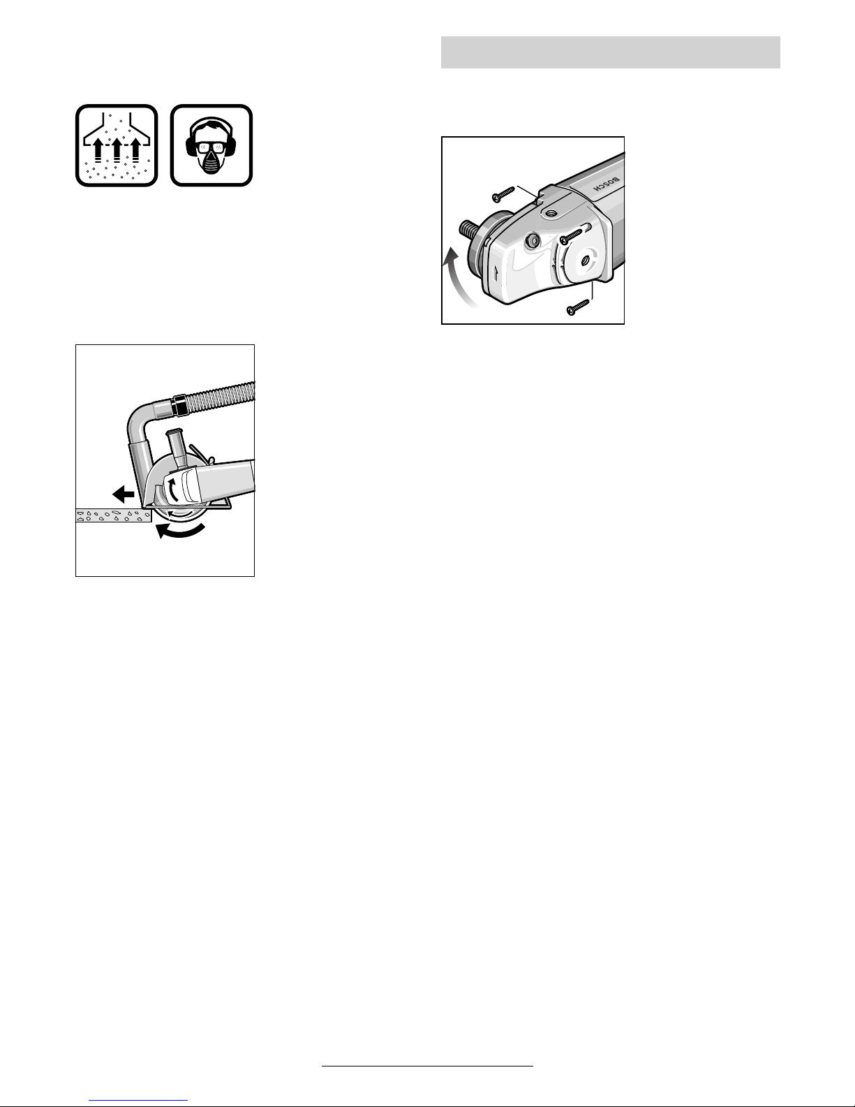
Français - 8
Tronçonnage de pierres
■ L’appareil ne doit être utilisé que pour la
coupe à sec/le ponçage à sec.
Le mieux est d’utili-
ser un disque de
tronçonnage diamanté. Pour empêcher les inclinaisons,
utiliser le chariot de
guidage 26 avec le
capot de protection
spécial à aspiration
de poussières.
N’utiliser l’appareil qu’avec une aspiration de
poussières. Porter aussi un masque de protection anti-poussières.
L’aspirateur doit être
conçu pour l’aspiration des poussières
de pierre.
La société Bosch
vous offre des aspirateurs appropriés.
Mettre l’appareil en
fonctionnement et le
positionner avec la
partie avant du chariot de guidage sur la
pièce à travailler.
Travailler en appliquant une vitesse d’avance
modérée adaptée au matériau (voir figure).
Lors du tronçonnage de matériaux particulière-
ment durs, par exemple de béton ayant une teneur élevée en cailloux, le disque de tronçonnage diamanté risque de chauffer et de subir
ainsi des dommages. Une couronne d’étincelles
autour du disque de tronçonnage diamanté en
est le signe.
Dans ce cas-là, interrompre le processus de tronçonnage et laisser tourner pendant quelque
temps le disque à tronçonnage diamanté sans
sollicitation et en marche à vide afin de le laisser
refroidir.
Un ralentissement perceptible du rythme de travail et une couronne d’étincelles circonférentielle
constituent des indices d’émoussage du disque
de tronçonnage diamanté. Il peut être aiguisé de
nouveau en coupant dans un matériau abrasif
(p. ex. brique de sable calcaire).
■ Avant toute intervention sur l’appareil, tou-
jours retirer la fiche du câble d’alimenta-
tion de la prise de courant.
Il est possible de
tourner la tête de
l’appareil par étapes
de 90° par rapport
au carter de l’appa-
reil. Ceci permet de
mettre l’interrupteur
Marche/Arrêt dans
une position de maniement favorable à
des utilisations spé-
cifiques; p. ex. pour
des travaux de tronçonnage avec chariot de
guidage 26 (accessoire, non vendu en France)/
support de tronçonnage 29 (accessoire) ou pour
les gauchers.
Dévisser complètement les quatre vis.
Tourner la tête de l’appareil avec précaution et
sans la détacher du carter dans sa nouvelle position.
Remettre les vis en place et bien les serrer.
Rotation de la tête de l’appareil
31 • 1 609 929 F55 • TMS • 18.12.03
 Loading...