


GWH-260-PN-N
GWH 260 PN
INDOOR MODEL
Flow Modulated with Standing pilot
Suitable for heating potable water only - Not approved for space heating purposes
(Intended for variable flow applications with steady cold water inlet temperatures)
GWH-260-PN-N
GWH-260-PN-L
6 720 608 126 US (06.05) AL
Warning: If the information in this manual is not
followed exactly, a fire or explosion may result
causing property damage, personal injury or death.
Do not store or use gasoline or other flammable
vapor and liquids in the vicinity of this or any other
appliance.
Improper installation, adjustment, alteration,
service or maintenance can cause injury or
property damage. Refer to this manual. For
assistance or additional information consult a
qualified installer, service agency or the gas
supplier.
In the Commonwealth of Massachusetts this
product must be installed by a licensed plumber or
gas fitter.
Upon completion of the installation, these
instructions should be handed to the user of the
appliance for future reference.
What to do if you smell gas
• Close gas valve. Open windows.
• Do not try to light any appliance.
• Do not touch any electrical switch; do not use any
phone in your building.
• Immediately call your gas supplier from a neighbor’s
phone. Follow the gas supplier’s instructions.
• If you cannot reach your gas supplier, call the fire
department.
• Installation and service must be performed by a
qualified installer, service agency or the gas supplier.
6 720 608 126
2
Index
Index
1 Warning 2
2 Appliance details 3
2.1 GWH 260 PN specifications (Technical data) 3
2.2 Unpacking the GWH 260 PN heater 4
2.3 General rules to follow for safe operation 4
2.4 Dimensions and installation clearances 5
3 Installation instructions 6
3.1 Introduction 6
3.2 Proper location for installing your heater 6
3.3 Heater placement and clearances 6
3.4 Mounting Heater 7
3.5 Combustion air requirements 8
3.6 Venting 9
3.7 Gas piping & connections 11
3.8 Measuring gas pressure 13
3.9 Water connections 13
3.10 Recirculation application 14
4 Operation instructions 14
4.1 For your safety read before operating your water heater 14
4.2 Lighting instructions 15
4.3 To turn off appliance 15
4.4 Setting the water temperature 16
4.5 Draining water from heater 16
5 Maintenance and service 17
5.1 Maintenance intervals 17
5.2 Water valve 17
5.3 Pilot 17
5.4 Main burners 18
5.5 Vent assembly 18
5.6 Mineral scale build-up 18
6 Troubleshooting 19
6.1 Introduction 19
6.2 Pilot does not light 19
6.3 Pilot lights, but goes out when button is released 19
6.4 Pilot goes out during or after hot water use 19
6.5 Burners do not light with water flow 20
6.6 Hot water temperature fluctuates at tap 20
6.7 Water is too hot 21
6.8 Water is not hot enough 21
6.9 Burners ignite without hot water flow 21
6.10 Low hot water pressure 21
6.11 Noise when heater is running 21
6.12 Burners do not operate cleanly; yellow flames
when operating 22
7 Protecting the environment 23
8 Interior components and diagram parts list 24
8.1 Interior components 24
8.2 Components diagram 25
8.3 Parts list 26
9 Fifteen Year Limited Warranty 27
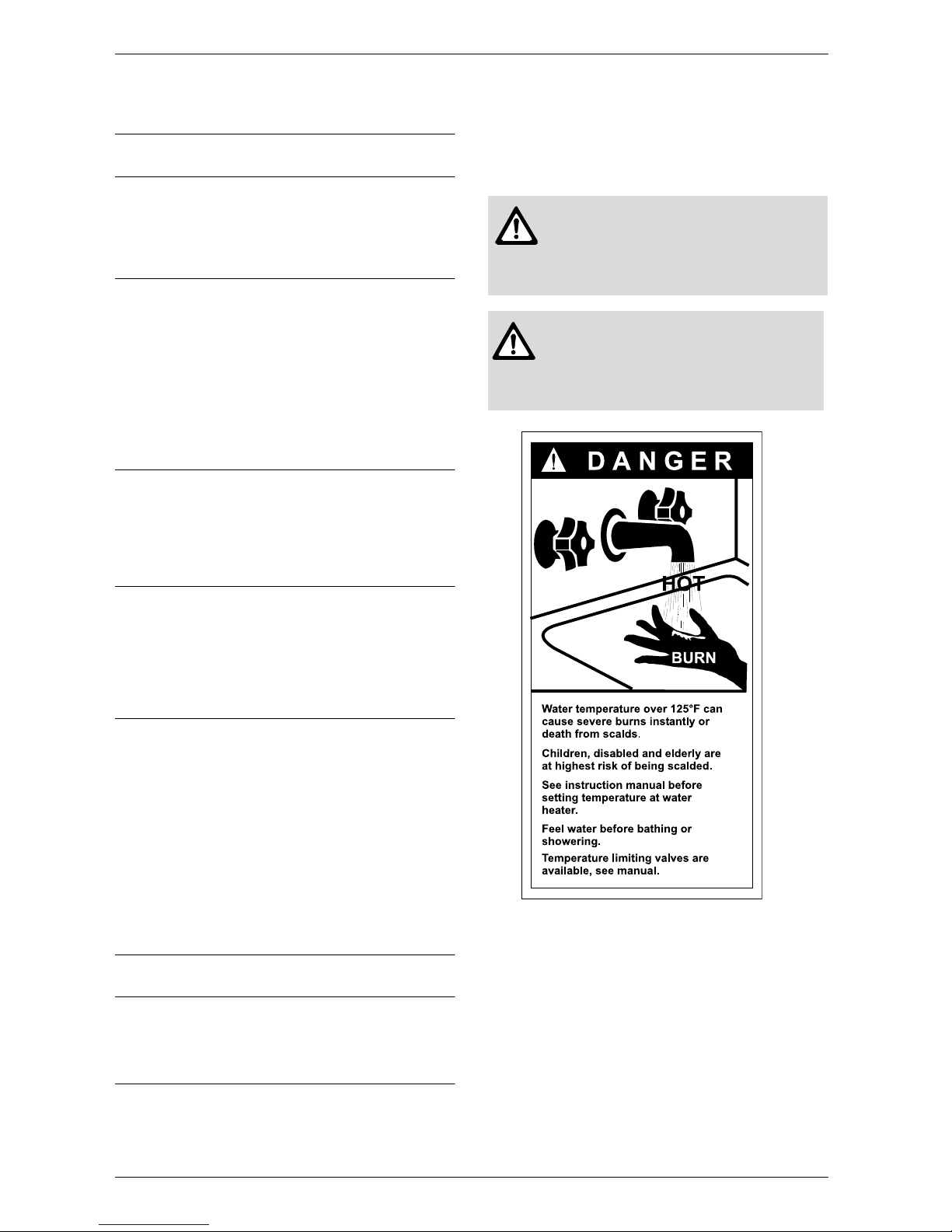
1 Warning
Fig. 1
Warning: The heater must be isolated
from the gas supply piping system
during any pressure testing of that
system at test pressures equal to or
more than 0.5 psig.
Caution: Any changes or
modifications not expressly approved
by the party responsible for compliance
could void the user’s authority to
operate the equipment.

6 720 608 126
Appliance details
3
2 Appliance details
2.1 GWH 260 PN specifications
(Technical data)
Approved in US/Canada
Capacity
GWH 260 PN: 2.6 GPM
Maximum output
GWH 260 PN: 58 400 Btu/hr
Maximum input
GWH 260 PN: 74 900 Btu/hr
Efficiency in %
Recovery efficiency 78%
Min. Output
GWH 260 PN: 23 906 Btu/hr
Gas Requirement
Gas connection (inches) - ½” NPT
Inlet gas pressure under maximum operation*
• Propane: 10.5” - 14” water column
• Natural Gas: 5.7” - 14” water column.
* To measure Gas Pressure, see Measuring Gas
Pressure, chapter 3.8.
Venting
• Natural Draft
• Vent diameter (inches) - 4”
• Minimum height (feet) - 6’ with no elbows
• Vertical termination.
Water
• Hot water connection (inches) - ½” NPT
• Cold water connection (inches) - ½” NPT
• Water valve material: Polymer (PPS) (Polypropylene
Sulfid)
• Minimum water flow: 0.5 gallon/minute (1.9 l/m)
• Minimum recommended water pressure: 13 PSI
(0.9 bar)
• Connections:
– Bottom of heater
Dimensions
• Depth (in): 8.66” (220 mm)
• Width (in): 12.20” (310 mm)
• Height (in): 22.83” (580 mm)
• Weight: 26 pounds (12 kg).
Gas types
Natural Gas.
LP Gas
Safety devices
• Flame failure device (ionization thermocouple)
• Pressure relief valve (supplied with heater)
• Over heat prevention (temperature limiter).
Water resistant
IP X4.
6 720 608 126
4
Appliance details
2.2 Unpacking the GWH 260 PN heater
This heater is packed securely.
Before installing the unit, be certain you have the
correct heater for your type of Gas - Propane or
Natural Gas. Identification labels are found on the
shipping box, and on the rating plate which is located on
the right side panel of the cover.
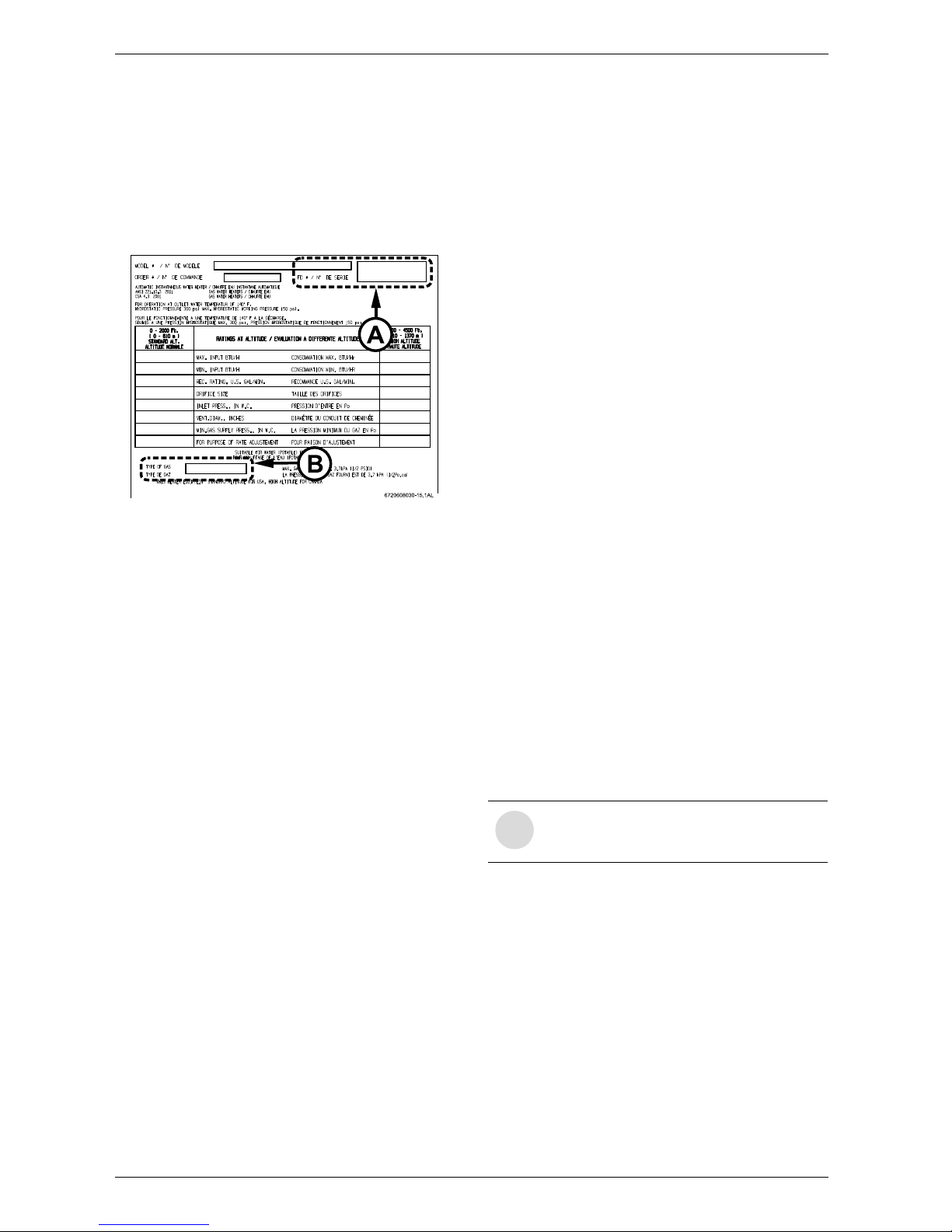
Fig. 2 Rating plate
A Serial number
B Type of gas
The box includes:
• Pressure relief valve
• Mounting screws
• Product registration card
• Installation manual
• Incandescent particle tray.
Do not lose this manual, there is a charge for a
replacement.
Please complete and return the enclosed product
registration card.
The GWH 260 PN is not approved or designed for:
• Manufactured (mobile) homes, RV's or boats
• Heating or other recirculating/pumping applications*
• Solar/preheat backup or high temperature booster
use
• Installation in a bathroom or other occupied rooms
normally kept closed.
* This includes domestic hot water circulator pump loop
systems that may be installed in home hot water system
prior to installing this unit. An approved recirculation
design can be found in chapter 3.10.
2.3 General rules to follow for safe
operation
1. You should follow these instructions when you install
your heater. In the United States: The installation must
conform with local codes or, in the absence of local
codes, the National Fuel Gas Code ANSI Z223.1/
NFPA 54.
In Canada: The Installation should conform with CGA
B149.(1,2) INSTALLATION CODES and /or local
installation codes.
2. Carefully plan where you install the heater. Proper
clearances must be followed.
3. The appliance must be isolated from the gas supply
piping system by closing its individual manual gas
shutoff valve (not supplied with heater) during any
pressure testing at pressures in excess of ½ Psig (3.5
kPa).
The appliance and its gas connection must be leak
tested before placing the appliance in operation.
4. Keep water heater area clear and free from
combustibles and flammable liquids. Do not locate the
heater over any material which might burn.
5. Correct gas pressure is critical for the optimum
operation of this heater. Gas piping must be sized to
provide the required pressure at the maximum output of
the heater, while all the other gas appliances are in
operation. Check with your local gas supplier, and see
chapter 3.7 and 3.8 to verify proper gas line sizing.
6. Should overheating occur or the gas supply fail to
shut off, turn off the gas supply at the manual gas shut
off valve, on the gas line. Note: manual gas shutoff valve
is not supplied with the heater.
7. Do not use this appliance if any part has been
underwater. Immediately call a qualified service
technician to inspect the appliance and to replace any
part of the control system and any gas control which
has been underwater.
i
BOSCH is constantly improving its
products, therefore specifications are
subject to change without prior notice.
6 720 608 126
Appliance details
5
2.4 Dimensions and installation clearances
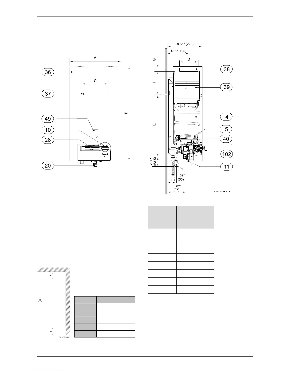
Fig. 3 Dimensions in Inches and (mm)
4 Heat exchanger
5 Burner
10 Temperature control
11 Water valve
20 Gas connection
26 Output control
36 Front cover
37 Hole for fixing to wall
38 Exhaust pipe to connector
39 Draft diverter with flue gas monitor
40 Gas valve
49 Observation window
102 Piezo
Fig. 4 Minimum clearances
Model GWH 260
TOP (A)
12 inches (306 mm)
FRONT (B)
4 inches (100 mm)
BACK
0 inches
SIDES
4 inches (100 mm)
BOTTOM (C)
12 inches (306 mm)
Dimensions inches
(mm)
GWH 260 PN
A 12.20” (310)
B 22.83” (580)
C 9” (228)
D 4” (100)
E 20.71” (526)
F 2.36” (60)
G 1” (25)
H 1/2”
Table 1 Dimensions in inches (mm)
6 720 608 126
6
Installation instructions
3 Installation instructions
3.1 Introduction
Please follow these instructions. Failure to follow
instructions may result in:
B Damage or injury.
B Improper operation.
B Loss of warranty.
If you are unable to perform the tasks required to install
this heater properly, please contact a locally licensed
plumber or gas technician.
Please contact Bosch Water Heating with any
questions.
3.2 Proper location for installing your
heater
Carefully select the location of the water heater. For
your safety and for proper heater operation, you must
provide combustion air to the heater and a proper
exhaust vent system.
Follow the guidelines below:
B 1. Locate the heater where venting, gas and
plumbing connections are feasible and convenient.
B 2. The hot water lines should be kept short to save
energy. Centrally locating the water heater is best. It
is always best to have hot water lines insulated.
3.3 Heater placement and clearances
The GWH 260 PN is design certified for installation on
a combustible wall (see 3.4 Mounting installation)
provided the wall is not covered with carpet or other
fabric material. For installations in an alcove or closet,
maintain the minimum clearances to combustible and
non-combustible materials listed below. See also Fig. 4.
A. Top 12 inches (306 mm)
B. Front 4 inches (100 mm)
C. Back 0 inches
D. Sides 4 inches (100 mm)
E. Bottom 12 inches (306 mm)
Warning: The water in this water
heater is cold and always remains cold
except for the times that hot water is
being used. DO NOT INSTALL IN AN
AREA WHERE IT COULD FREEZE.
Drain the heater entirely if freezing
temperatures are anticipated in area
where heater is installed. See chapter
4.5 for draining instructions.
To prevent freeze damage from residual
water in the heater, introduce short
bursts of compressed air (20-40psi)
through these connections to remove
the residual water in the horizontal
pipes and water valve.
Warning: Flammable materials,
gasoline, pressurized containers, or any
other items or articles that are potential
fire hazards must NOT be placed on or
adjacent to the heater. The appliance
area must be kept free of all
combustible materials, gasoline and
other flammable vapors and liquids.
Warning: The heater must be isolated
from the gas supply piping system
during any pressure testing of that
system at test pressures equal to or
more than 0.5 psig.
Warning: Place the heater in a location
where water leaks will do NO DAMAGE
to adjacent areas.
6 720 608 126
Installation instructions
7
3.4 Mounting Heater
Remove cover and inspect.
B Remove the temperature control.
B Unscrew the cover fixing screws, see Fig. 6.
B Remove the outer case by sliding it forwards and
then lifting upwards.
B Ensure that the flue terminal is clear.
B After inspection, replace front cover and tighten
screws.
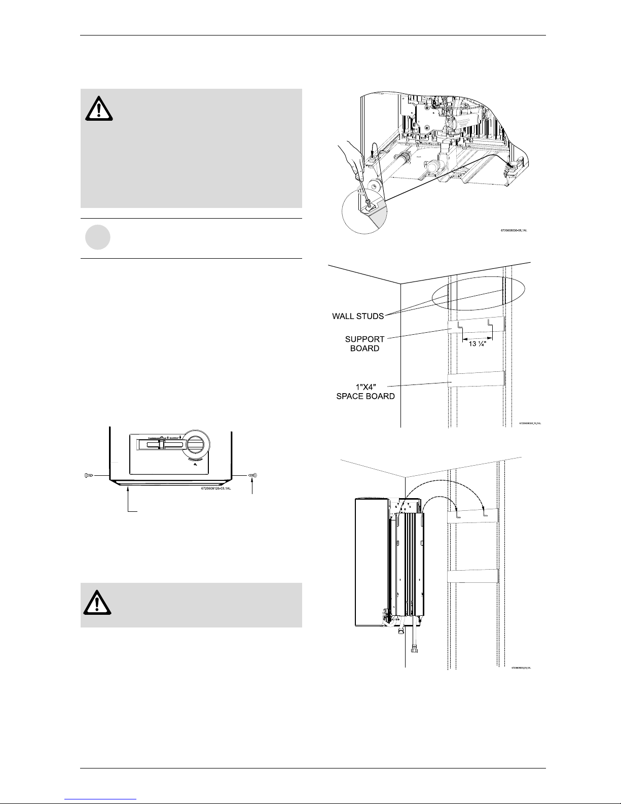
Install incandescent particle tray.
B Install incandenscent particle tray using screws
provided as shown in Fig. 5.
Fig. 5 Incandescent particle tray illustration
Mounting heater.
The GWH 260 PN is design certified for mounting on a
wall.
The heater must be mounted on a wall using
appropriate anchoring materials. If wall is a stud wall
sheathed with plasterboard, it is recommended that
support board(s), either 1x4’s or 1/2" (minimum)
plywood first be attached across a pair of studs and
then the heater should be attached to the support
boards, see Fig. 7.
B Secure the two included L shaped hooks to wall
studs or support board 13 1/4” apart. (See Fig. 7).
B Hang heater on two L shaped hooks. (See Fig. 8).
Fig. 6 Remove front cover
Fig. 7 Support board
Fig. 8 Secure heater to wall
Warning: before starting installation:
B check that there are no loose parts
inside the appliance
B ensure that gas pipe, gas valve, and
burner have no damage and are
properly fitted.
B Read chapter 2.2 to verify proper gas
type and to check all parts are included
in box.
i
Front cover should be removed in order to
inspect components visually (see
instructions below).
Warning:
B Do not install this appliance on a
carpeted wall.
Incandescent particle tray
Screws

6 720 608 126
8
Installation instructions
3.5 Combustion air requirements
The BOSCH PRO water heater holds cold water in its
copper heat exchanger and water valve when not in use.
Because of this, any cold air that comes down through
the unit's vent pipe is capable of freezing these
components. This Installation Manual specifies the
minimum vertical vent pipe and the amount of
combustion air required for this unit. When all
requirements are followed, the unit will operate properly
and safely. However, there may still be a risk of freezing
due to negative draft if all the combustion appliances in
the building or structure are not being supplied with a
sufficient amount of make-up air. A wood stove or
furnace can pull outside air down through the BOSCH
PRO vent pipe and across the heat exchanger tubing. If
the air is cold enough, the heat exchanger is at risk of
freezing and bursting. Supplying more combustion air
for all combustion appliances is the solution. Follow the
instruction on venting and checking the adequacy of
make up air. A HVAC specialist should be consulted on
how to provide more combustion air if necessary.
Observe the following instructions concerning
combustion air.
Appliances located in unconfined spaces:
a) An unconfined space is one whose volume is greater
than 50 cubic feet per 1000 Btu per hour of the
combined rating of all appliances installed in the space.
That would be 5850 cubic feet for the BOSCH PRO
GWH 260 PN alone.
b) Installations in structures that have been tightly
constructed (air infiltration rate of 0.40 ACH or less)
must be provided for combustion air per the National
Fuel Gas Code. Consult a HVAC specialist if your air
infiltration rate is questionable.
Appliances located in confined spaces:
The confined space must be provided with two
permanent openings, one commencing within 12
inches of the top and one commencing within 12 inches
of the bottom of the enclosure. Each opening must have
a minimum free area of one square inch per:
• 1000 Btu/hr if all air is taken from inside the building.
• 2000 Btu/hr if all air is taken from the outside by
horizontal ducts.
• 4000 Btu/hr if all air is taken from the outside by
direct openings or vertical ducts.
Or the confined space must be provided with one
permanent opening or duct that is within 12 inches of
the ceiling of the enclosure. This opening must have a
minimum free area of one square inch per:
• 3000 Btu/hr if all air is taken from the outside by a
direct opening or vertical duct.
Louvers, grills and screens have a blocking effect. If the
effective free area is not known, increase the sizes of
your openings by 400% if your louvers are wood and by
135% if your louvers are metal. Refer to the National
Fuel Gas Code for complete information. In buildings of
tight construction all air should be taken from outside.
6 720 608 126
Installation instructions
9
3.6 Venting
B Minimum vent pipe diameter: 4 inches
B Minimum vertical vent height: 6 feet, with no elbows
B Establish 12 inch rise before any elbow
The heater must be vented to the outside following all
local ordinances and specifications for installing a gas
appliance vent or chimney. The heater must be located
as close as practicable to a vertically rising chimney or
vent that has a listed vent cap at its termination point.
The venting system must be designed and constructed
so as to develop a positive flow adequate to remove flue
gasses to the outdoors. Consult the National Fuel Gas
Code if the vent will have elbows or share venting with
another natural draft appliance.
3.6.1 Horizontal venting
3.6.2 Vertical venting
B A 4 inch diameter gas vent constructed of double
wall Type B gas vent is recommended. Under no
circumstances should the vent pipe be reduced in
size.
B An approved gas vent connector must be attached to
the top of the water heater and rise vertically at least
12" before entering into an approved gas vent
connector elbow.
B The minimum vertical gas vent height allowed is 6
feet; horizontal vent connectors and elbows are not
to be considered in the total gas vent height.
B All gas vent sections must be secured to each other
with sheet metal screws and be properly supported.
Horizontal runs:
Any gas vent section that is greater than 45 degrees
from the vertical is considered horizontal. Horizontal
sections must slope upwards at least ¼ inch for every
foot of its horizontal length and be properly supported.
Keep the horizontal section short and avoid too many
elbows. The maximum horizontal run allowed is half of
the total vertical vent height; horizontal vent connectors
and elbows are not to be considered in the total gas
vent height.
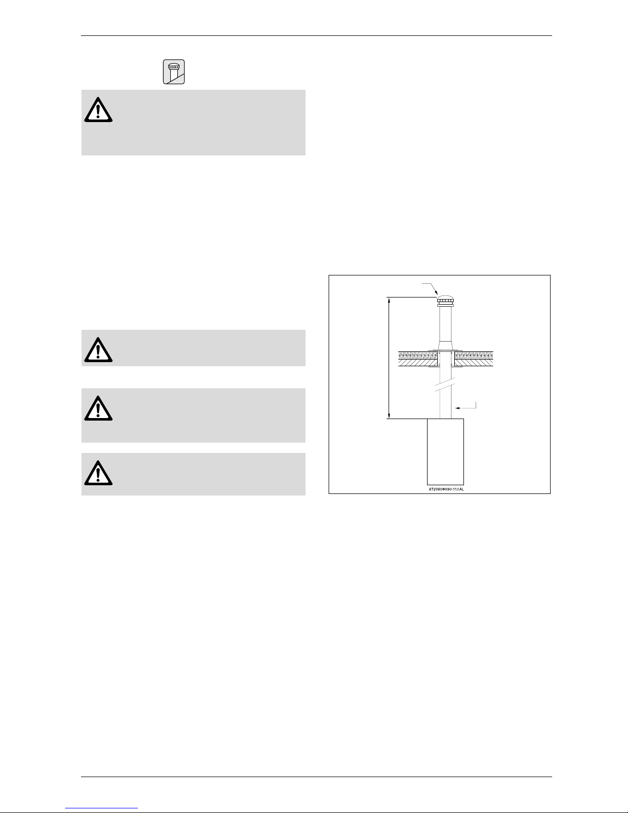
Vent termination:
The gas vent constructed of double wall Type B gas
vent must terminate above the roof surface with a listed
vent cap at a height that's in accordance with Fig. 10
and table 2, provided it is at least 8 feet (2.4 m) from a
vertical wall or similar obstruction. All other gas vents
that are not able to terminate within the minimum
specified height allowed must terminate not less than 2
feet (0.6 m) above the highest point where it's passed
through the roof and at least 2 feet (0.6 m) higher than
any vertical wall or similar obstruction within 10 feet (3.1
m).
Fig. 9 Flat roof
Danger: Do not reduce the vent pipe
size. Do not put an elbow directly on top
of heater. Failure to follow venting
requirements may cause dangerous
exhaust gases to enter living space.
Warning: Do not combination vent with
a mechanically vented appliance.
Warning: Horizontally venting to a
vertically constructed vent stack along
an outside wall of a building is not
permissible.
Warning: Horizontally venting to a
sidewall vent terminator is not
permissible
LISTED VENT CAP
MINIMUM 6
FEET (1.8M)
LISTED GAS VENT
ESTABLISH A ONE
FOOT RISE BEFORE
ANY ELBOWS
 Loading...