


GWH 425 HN
Water heaters for use with Natural and L.P.G.
GWH 425 HN
Flow Modulated with Electronic Ignition
Suitable for heating potable water only - Not approved for space heating purposes
(Intended for variable flow applications with steady cold water inlet temperatures)
GWH-425-HN-N
GWH-425-HN-L
6 720 607 026 US (04.11) AL
Warning: If the information in this manual is not
followed exactly, a fire or explosion may result
causing property damage, personal injury or death.
Do not store or use gasoline or other flammable
vapor and liquids in the vicinity of this or any other
appliance.
Improper installation, adjustment, alteration,
service or maintenance can cause injury or
property damage. Refer to this manual. For
assistance or additional information consult a
qualified installer, service agency or the gas
supplier.
In the Commonwealth of Massachusetts this
product must be installed by a licensed plumber or
gas fitter.
Upon completion of the installation, these
instructions should be handed to the user of the
appliance for future reference.
What to do if you smell gas
• Close gas valve. Open windows.
• Do not try to light any appliance
• Do not touch any electrical switch; do not use any
phone in your building
• If you cannot reach your gas supplier, call the fire
department.
• Immediately call your gas supplier from a neighbor’s
phone. Follow the gas supplier’s instructions.
• Installation and service must be performed by a
qualified installer, service agency or the gas supplier.

2 6 720 607 026
WARNING: Improper installation,
adjustment, alteration, service or maintenance can cause
injury or property damage. Refer to this manual. For
assistance or additional information consult a qualified
installer, service agency or the gas supplier.
Upon completion of the installation, these instructions
should be handed to the user of the appliance for future
reference.
In the Commonwealth of Massachusetts this product
must be installed by a licensed plumber or gas fitter.
WARNING
If the information in this manual is not followed exactly, a
fire or explosion may result causing property damage,
personal injury or death.
FOR YOUR SAFETY
Do not store or use gasoline or other flammable,
combustible or corrosive vapors and liquids in the vicinity
of this or any other appliance.
WHAT TO DO IF YOU SMELL GAS
- Do not try to light any appliance.
- Do not touch any electrical switch; do not use any
phone in your building.
- Immediately call your gas supplier from a neighbor’s
phone. Follow the gas supplier’s instructions.
- If you cannot reach your gas supplier, call the fire
department.
- Installation and service must be performed by a
qualified installer, service agency or the gas supplier.
Specifications................................................................ Page 3
Rules for safe operation .............................................. Page 5
Locating the Heater ..................................................... Page 5
Combustion Air Requirements ................................... Page 6
Mounting the Heater .................................................... Page 6
Venting the Heater ....................................................... Page 7
Gas Connections ......................................................... Page 9
Gas Piping.................................................................... Page 10
Water Connections .................................................... Page 11
Safety before turning on the heater .......................Page 11
Operating instructions ...............................................Page 12
Setting water temperature ........................................Page 12
Maintenance & Service ............................................. Page 13
Trouble Shooting ......................................................... Page 13
Electrical Diagram ...................................................... Page 15
Diagram of 425HN..................................................... Page 17
Interior components diagram .................................... Page 18
Parts List ....................................................................... Page 19
Flowchart ..................................................................... Page 20
Warranty .......................................................................Page 21
TABLE OF CONTENTS

36 720 607 026
Principle of Operation:
When a hot water faucet is opened, the water flow through
the heater causes the gas valve to open. At the same time
the hydro-generator activates the electronics which sends
a spark to the pilot. The flame sensor confirms the pilot has
been lighted and allows the first two burners to come on.
The flame sensor confirms correct activation and all burners
come on. The pilot goes off. The heat exchanger coils absorb
the heat generated by the burners and transfer heat to the
water. When the hot water faucet is shut off, the gas valve
automatically closes and the burners turn off. Your hot water
faucet is an ignition key to activate the water heater, giving
you control over your hot water energy use. Every time you
turn off your hot water faucet, the energy consumption of
your hot water returns to zero.
FEATURES
- Electronic Pilot Ignition driven by hydro-generator
- High Quality Materials for Long Working Life.
- Copper heating coils for endless supply of hot water.
- Burner output proportional to hot water flow demand for
maximum energy efficiency.
- Safety flame sensor at pilot burner.
- Automatic overheating protection shut-off sensor.
- Flue gas safety device.
- Stainless steel burners with stabilized blue flame.
- Built-in corrosion resistant draft diverter.
- Compact space saver: mounts on a wall with two hooks.
- Easily removable one-piece cover.
- Easy one person installation.
- Adjustable water flow restrictor to ensure that water flow
demand will not exceed the heating capacity of the heater.
- On/Off Switch to activate system.
- Red LED indicator flashes with low water pressure.
- Green LED indicator main burner operation.
BOSCH is constantly improving our products, therefore
specifications are subject to change without prior notice.
425 HN LP and 425 HN NG Specifications
Gas Input max.: 117,000 Btu/hr
min.: 28,000 Btu/hr
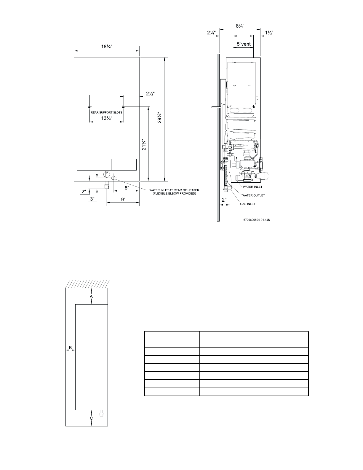
Water Connection ½” Thread fitting NPT
H x W x D 29 3/4” x 18 1/4” x 8 3/4"
Vent 5”
Gas Connection 1/2” NPT thread
Min. Water Pressure 18 Psi at 4 GPM
Max. Water Pressure 150 Psi
Shipping Weight 43 LB
Net Weight 40 LB
1.8 GPM at 90° rise
3.7 GPM at 45° rise
Min. Water Flow 1/2 gal/min
LP GAS Supply Pressure
(before 425 HN regulator) min. 11” W.C.
max. 14” W.C.*
Required LP GAS Pressure at inlet
tap while 425 HN is operating: 10.5” W.C.
LP GAS Burner Manifold pressure while 425 HN is
operating at maximum input: 9.0” W.C.
Natural Gas Supply Pressure min.: 7” W.C.
(before 425 HN regulator) max.: 14” W.C.*
Required Natural Gas Pressure at inlet
tap while 425 HN is operating: 5.7” W.C.
Natural Gas Burner Manifold Pressure while 425 HN is
operating at maximum input: 4.2” W.C.
* Inlet gas pressure before 425 HN regulator must not exceed
this value. Pressure may need to be adjusted for high
altitudes, see page 7.
UNPACKING THE 425 HN HEATER
This heater is packed securely. The box includes one water connection fitting, a control knob with collar, a gas pressure
regulator, a pressure relief valve, an incandescent particle tray, two hooks for hanging the heater, this manual and a
warranty registration card. Do not lose this manual, as there is a charge for replacement. Please complete and return
the enclosed warranty registration card.
4 6 720 607 026
MINIMUM INSTALLATION CLEARANCES FROM COMBUSTIBLE AND NON
COMBUSTIBLE MATERIALS FOR ALCOVE OR CLOSET INSTALLATIONS
FRONT VIEW SIDE VIEW
MODEL 425HN
MODEL 425 HN
TOP (A) 12"
FRONT (B) 4"
BACK 0"
SIDES 4"
FLOOR (C) 12"
VENT DIAMETER 5"
56 720 607 026
GENERAL RULES TO FOLLOW
FOR SAFE OPERATION
1. You should follow these instructions when you install your
heater. In the United States: The installation must conform
with local codes or, in the absence of local codes, the
National Fuel Gas Code ANSI Z223.1/NFPA 54.
In Canada: The Installation should conform with CGA
B149.(1,2) INSTALLATION CODES and /or local installation
codes.
2. Carefully plan where you install the heater. Correct
combustion air supply and flue pipe installation are very
important. If not installed correctly, fatal accidents can be
caused by lack of air, carbon monoxide poisoning or fire.
3. The place where you install the heater must have enough
ventilation. The National Fire Codes do not allow gas fired
water heater installation in bathrooms, bedrooms or any
occupied rooms normally kept closed. See the section below
on locating the heater.
4. You must vent your heater. See section on VENTING,
Page 6.
5. The appliance must be disconnected from the gas supply
piping system during any pressure testing at pressures in
excess of 1/2 Psig (3.5 kPa).
The appliance must be isolated from the gas supply piping
system by closing its individual manual shutoff valve during
any pressure testing of the gas supply piping system at test
pressures equal to or more than 1/2 Psig (3.5Kpa). The
appliance and its gas connection must be leak tested before
placing the appliance in operation.
6. Keep water heater area clear and free from combustibles
and flammable liquids. Do not locate the heater over any
material which might burn.
7. Correct gas pressure is critical for the optimum
operation of this heater (see specifications on page 2). Gas
piping must be sized to provide the required pressure at the
maximum output of the heater, while all the other gas
appliances are in operation. Check with your local gas
supplier, and see the section on connecting the gas supply.
8. Should overheating occur or the gas supply fail to shut
off, turn off the gas supply at the manual gas shut off valve
on the gas line.
9. Do not use this appliance if any part has been underwater.
Immediately call a qualified service technician to inspect
the appliance and to replace any part of the control system
and any gas control which has been underwater.
PROPER LOCATION FOR INSTALLING YOUR
HEATER
Carefully select the location of your new heater. For your
safety and for proper heater operation, you must provide an
abundant supply of combustion air and a proper venting.
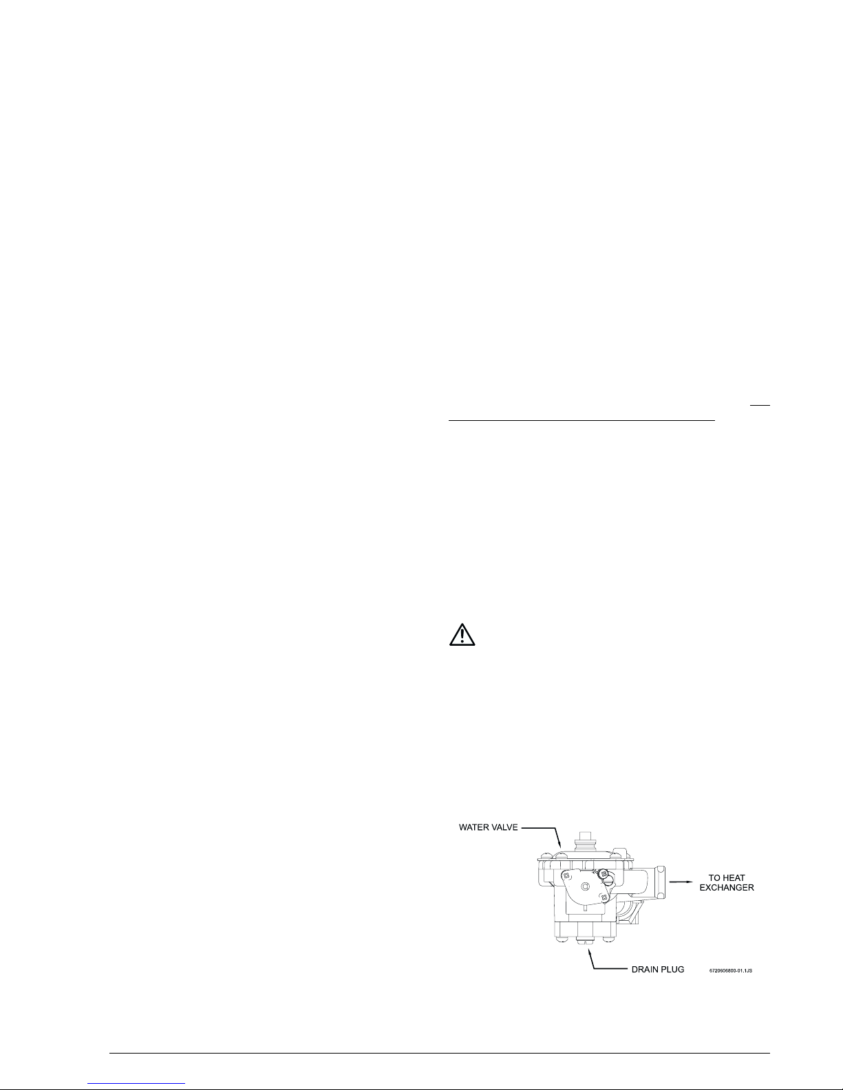
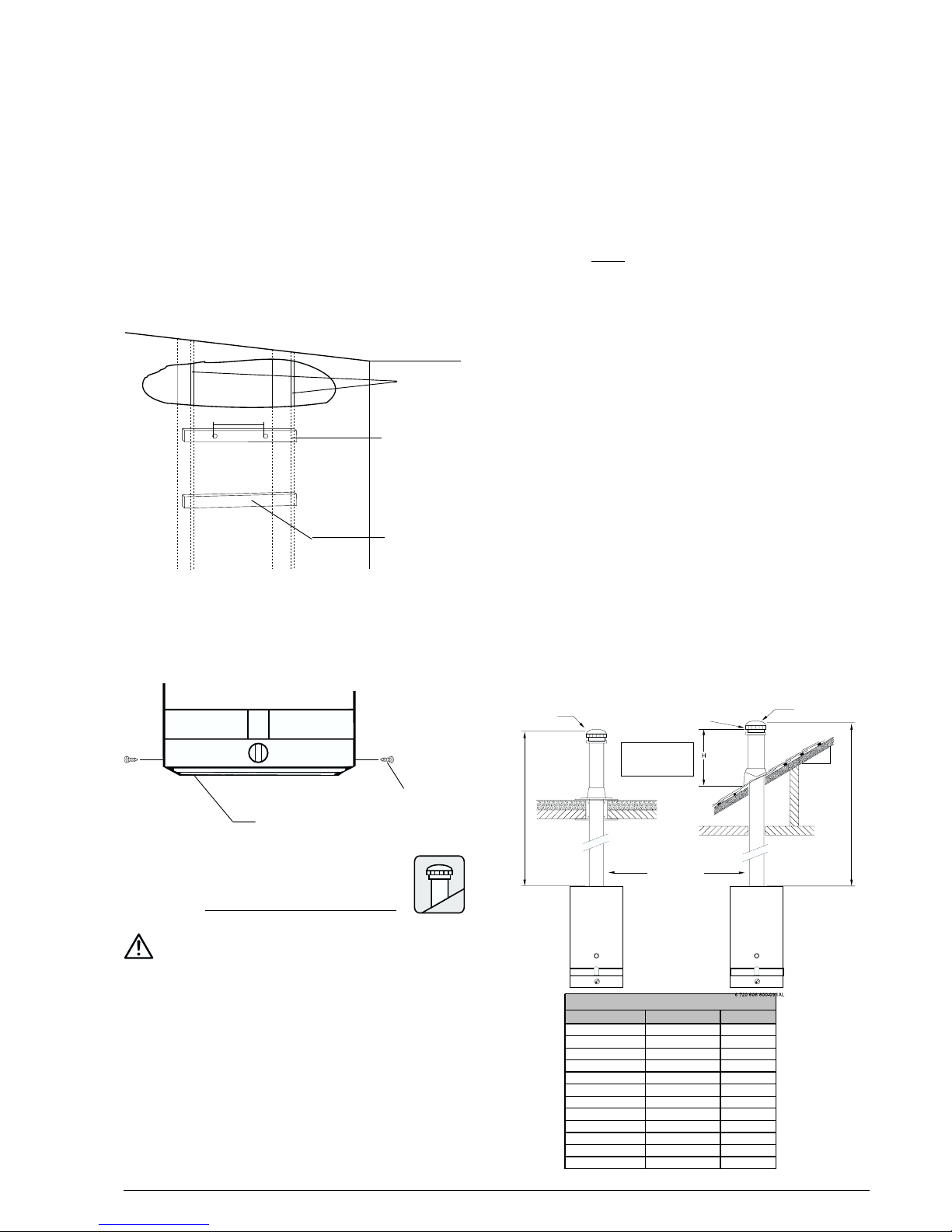
Fig. 1 - Water heater drain plug
The heater may still operate even when improperly vented.
It will, however, be less efficient and could eventually damage
the heater. It could even result in human sickness or death
due to oxygen deprivation and carbon monoxide poisoning.
Follow the guidelines below:
1. Place your heater as close to a vent or chimney as
possible.
2. National building codes require that you do not install
this appliance in bathrooms, bedrooms or any occupied
rooms normally kept closed.
3. Simultaneous operation of other appliances such as
exhaust fans, ventilation systems clothes dryers, fireplaces
or wood stoves could create a vacuum effect in your home
which could cause dangerous combustion by-products to
spill back into your home rather than venting to the outside
through the flue. Confirm that your 425 HN is venting
properly when all these other appliances are running. See
section on venting.
Do not obstruct the flow of combustion and ventilation
air to the appliance. If installed near a clothes dryer it is
very important that the dryer be properly vented. Failure to
properly vent a dryer could result in a gradual accumulation
of lint on the water heater fin coils and burners, leading to a
dangerous condition of vent blockage and poor unsafe
combustion.
4. Your hot water lines should be kept short to save energy.
It is always best to have hot water lines insulated.
5. This product is neither designed nor approved for outside
installations. This product is not approved for manufactured
homes (mobile home), recreational vehicles (RV) or boats.
Reference ANSI Z21.10.3.
WARNING: The water in this water heater is cold and
always remains cold except for the times that hot water is
being used DO NOT INSTALL IN AN AREA WHERE IT
COULD FREEZE.
This heater is neither designed for nor approved for
outside installation.
Drain the heater entirely if freezing temperatures are
anticipated in area where heater is installed by
disconnecting both the inlet and outlet water connections
from the heater (disconnect the outlet flex line from where
it connects to the copper heat exchanger). Additionally
remove the drain plug under the water valve. See Fig. 1.
6 6 720 607 026
WARNING: Flammable materials, gasoline,
pressurized containers, or any other items or articles
that are potentially fire hazards must NOT be placed on
or adjacent to the heater. The appliance area must be
kept free of all combustible materials, gasoline and other
flammable vapors and liquids.
COMBUSTION AIR REQUIREMENTS
The 425 HN water heater holds cold water in its copper
heat exchanger and brass water valve when not in use.
Because of this, any cold air that comes down through the
unit’s vent pipe is capable of freezing these components.
This Installation Manual specifies the minimum vertical vent
pipe and the amount of combustion air required for this unit.
When all requirements are followed, the unit will operate
properly and safely. However, there may still be a risk of
freezing due to negative draft if all the combustion appliances
in the area are not being supplied with a sufficient amount
of make-up air. A wood stove or furnace may pull combustible
air down through the 425 HN vent system, leaving the cold
infiltrating air capable of freezing the cold water in the 425
HN heat exchanger. More make up air is the solution. Follow
the instructions on venting and checking adequacy of make
up air. A HVAC specialist should be used to design solutions
for providing more make-up air if necessary.
Observe the following instructions concerning combustion
air.
Appliances located in unconfined spaces:
a) An unconfined space is one whose volume is greater
than 50 cubic feet per 1000 Btu per hour of the combined
rating of all appliances installed in the space. That would
be 5850 cubic feet for the 425HN alone.
b) In unconfined spaces in buildings of conventional frame,
masonry, or metal construction, infiltration is normally
adequate to provide air for combustion, ventilation, and
dilution of flue gasses.
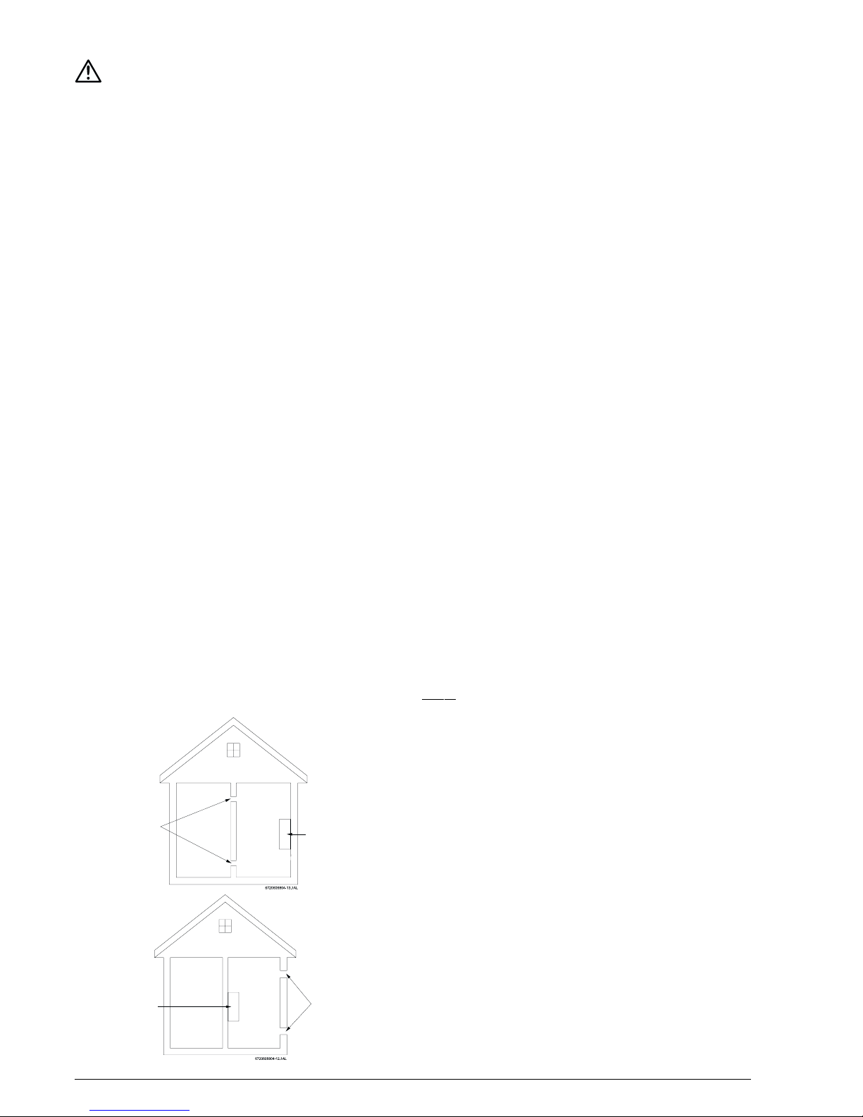
Appliances located in confined spaces:
The confined space must be provided with two permanent
openings, one commencing within 12 inches of the top and
one commencing within 12 inches of the bottom of the
enclosure. Each opening must have a minimum free area of
one square inch per:
- 1000 Btu/hr if all air is taken from inside the building.
- 2000 Btu/hr if all air is taken from the outside by horizontal
ducts.
- 4000 Btu/hr if all air is taken from the outside by direct
openings or vertical ducts.
Or the confined space must be provided with one permanent
opening or duct that is within 12 inches of the ceiling of the
enclosure. This opening must have a minimum free area of
one square inch per:
- 3000 Btu/hr if all air is taken from the outside by a direct
opening or vertical duct.
Louvers, grills and screens have a blocking effect. If the
effective free area is not known, increase the sizes of your
openings by 75% if your louvers are wood and by 30% if
your louvers are metal. Refer to the National Fuel Gas Code
for complete information. In buildings of tight construction
all air should be taken from outside.
CLEARANCES
The 425 HN is design certified for installation on a
combustible wall and for installation in an alcove or closet
with the minimum clearances to combustible and non combustible construction listed below
A. Top 12 inches (306 mm)
B. Front 4 inches (102 mm)
C. Back 0 inches
D. Sides 4 inches (102mm)
E. Bottom 12 inches (306 mm)
Clearance from vent is dependent upon the clearance rating
of the venting material used. For example: type B-1 vent is
approved for 1 inch clearance.
Note: Typically, the minimum clearence to combustible
materials should not be less than 6“ for single wall flue
pipe. Note that this clearance can be reduced if combustible
materials are protected as per table VI of the National Fuel
Gas Code or if Type B gas vent is used.
MO UN TI NG IN STAL LATI ON
The 425HN is design certified for mounting on a wall.
Secure the two L shaped hooks, which are provided with
heater, to a wall surface. Place them 13 ¼” apart as shown
in Fig. 2.
Do not install this appliance on a carpeted wall or over floor
covering which is combustible, such as carpet. The heater
must be mounted on a wall using appropriate anchoring
materials. If wall is a stud wall sheathed with plasterboard, it
is recommended that support board(s), either 1x4’s or
1/2" (minimum) plywood first be attached across a pair
of studs and then the heater should be attached to the
support boards. See Fig. 2.
Expansion and contraction of piping due to changing water
temperature in the pipes imparts movement to the heater
which, if mounted directly to a brittle, friable board, such as
425HN
Air Vents
(5 ½ X 5 ½ in. each)
Air Vents
(10 ¾ X 10 ¾ in. each)
425HN
76 720 607 026
VENTING
Vent pipe connection.
WARNING: Do not reduce the vent pipe size. See Fig. 4
for high altitude installations
The heater must be vented to the outside following all local
ordinances and specifications for installing a gas appliance
vent or chimney. The heater must be located as close as
practicable to a vertically rising chimney or vent that has a
listed vent cap at its termination point. The venting system
must be designed and constructed so as to develop a positive flow adequate to remove flue gasses to the outdoors.
Consult the National Fuel Gas Code if the vent will have
elbows or share venting with another natural draft
Roof pitch H (minimum) feet meters
Flat to 6/12 1.0 0.30
6/12 to 7/12 1.25 0.38
Over 7/12 to 8/12 1.5 0.46
Over 8/12 to 9/12 2.0 0.61
Over 9/12 to 10/12 2.5 0.76
Over 10/12 to 11/12 3.25 0.99
Over 11/12 to 12/12 4.0 1.22
Over 12/12 to 14/12 5.0 1.52
Over 14/12 to 16/12
6.0 1.83
Over 16/12 to 18/12 7.0 2.13
Over 18/12 to 20/12 7.5 2.27
Over 20/12 to 21/12 8.0 2.44
GAS VENT TERMINATIONS FOR LISTED VENT CAPS
Listed vent cap
Lowest discharge
opening
H (minimum) height
from roof to lowest
discharge opening
Roof Pitch
IS X/12
12
X
Listed gas vent
Figure A Figure B
Establish a one foot
rise before any elbows
MINI MUM 6 FEET (1.8M)
Listed vent cap
plasterboard, can cause failure of mounting.
In earthquake-prone zones, CEC recommends that installers
use a large washer and lag screw through the existing holes
used to hang the heater to affix the upper third of the heater
to the mounting board. To affix the lower third of the heater,
CEC recommends that two new holes be drilled in the
heater’s frame, each one 16 inches below the top two holes,
and that washers and lag screws be used to secure the
lower portion of the heater to a spacing board.
Before installing the unit, be certain you have the correct
heater for your type of Gas – Propane or Natural Gas.
Identification labels are found on the shipping box, and on
the rating plate which is located on the right side panel of
the cover. Also, each burner orifice is stamped with a number
(79 for LPG and 120 for Natural Gas).
Fig. 2 - Mounting the Heater
WALL STUDS
1” X 4”
SPACE BOARD
SUPPORT
BOARD
13 ¼ ”
Fig. 3 - Incandescent Particle Tray Illustration
The incandescent particle tray (shipped loose in the carton
with the water heater) must be attached at the bottom of
the water heater front cover at the time of installation. Use
the screws provided. See figure 3
SCREWS
INCANDESCENT PARTICLE TRAY
appliance. The heater should never be common vented
with a mechanically vented appliance. Single wall vent
pipe is not recommended, if used consult the National
Fuel Gas Code.
Horizontally venting to a sidewall vent terminator or a
vertically constructed vent stack along an outside wall of a
building is not permissible. A Powervent (Model AQ-1), with
a proof-of-draft safety interlock device, is required and is
available in order to sidewall vent. Contact your dealer. In
the Commonwealth of Massachusetts: Powervented
applications must utilize proof-of-draft safety interlock
device.
VERTICAL GAS VENT: A 5 inch diameter gas vent constructed
of double wall Type B gas vent is recommended. 6 inch is
required in elevations greater than 2000 feet, see Fig. 4.
Any gas vent section that is greater than 45 degrees from
the vertical is considered horizontal. Horizontal sections must
slope upwards at least ¼ inch for every foot of its horizontal
length and be properly supported. Keep the horizontal section
short and avoid too many elbows. The minimum vertical gas
vent height allowed is 6 feet; horizontal vent connectors
and elbows are not to be considered in the total gas vent
height. All gas vent sections must be secured to each other
with sheet metal screws and be properly supported.
The gas vent constructed of double wall Type B gas vent
must terminate above the roof surface with a listed vent
cap at a height that’s in accordance with Figure A or B and
their table, provided they are at least 8 feet (2.4 m) from a
vertical wall or similar obstruction. All other gas vents that
are not able to terminate within the minimum specified height
allowed must terminate not less than 2 feet (0.6 m) above
the highest point where it’s passed through the roof and at
least 2 feet (0.6 m) higher than any vertical wall or similar
obstruction within 10 feet (3.1 m).
8 6 720 607 026
To check the draft:
Close all doors and windows to the outside.
Turn on all appliances that force air out of the building.
These include all exhaust/ventilation fans, furnaces, clothes
dryers, wood burning stoves, etc.
Open all doors between the 425 HN and these other
appliances.
With the control knob set fully clockwise and strong hot
water flow rate, run the unit for at least 10 minutes. The
425 HN is equipped with a Flue Gas Sensor; it’s mounted
on the right side of the draft diverter (Flue Gas Sensor #34
on page 17). If the main burners shut off during this test it
is because the Flue Gas Sensor has detected inadequate
venting. This is a serious health hazard and must be corrected.
Poor venting can result in soot building up inside the heater,
overheating of the heater and freezing of the heat exchanger
in a freezing environment, which is all a result of negative
air flow. Additional combustion air and/or improved venting
will be necessary to correct this.
WARNING
Note: The burners of an instantaneous “on demand” water
heater such as the 425 HN are only on at the time that hot
water is actually being used, the vent pipe is therefore cold
except for the short durations when hot water is being used,
it is therefore very important that the venting and air supply
be adequate to provide a good positive draft as soon as the
burners turn on.
The 425 HN instantaneous water heaters have built-in draft
diverters and are designed for indoor installation only. The
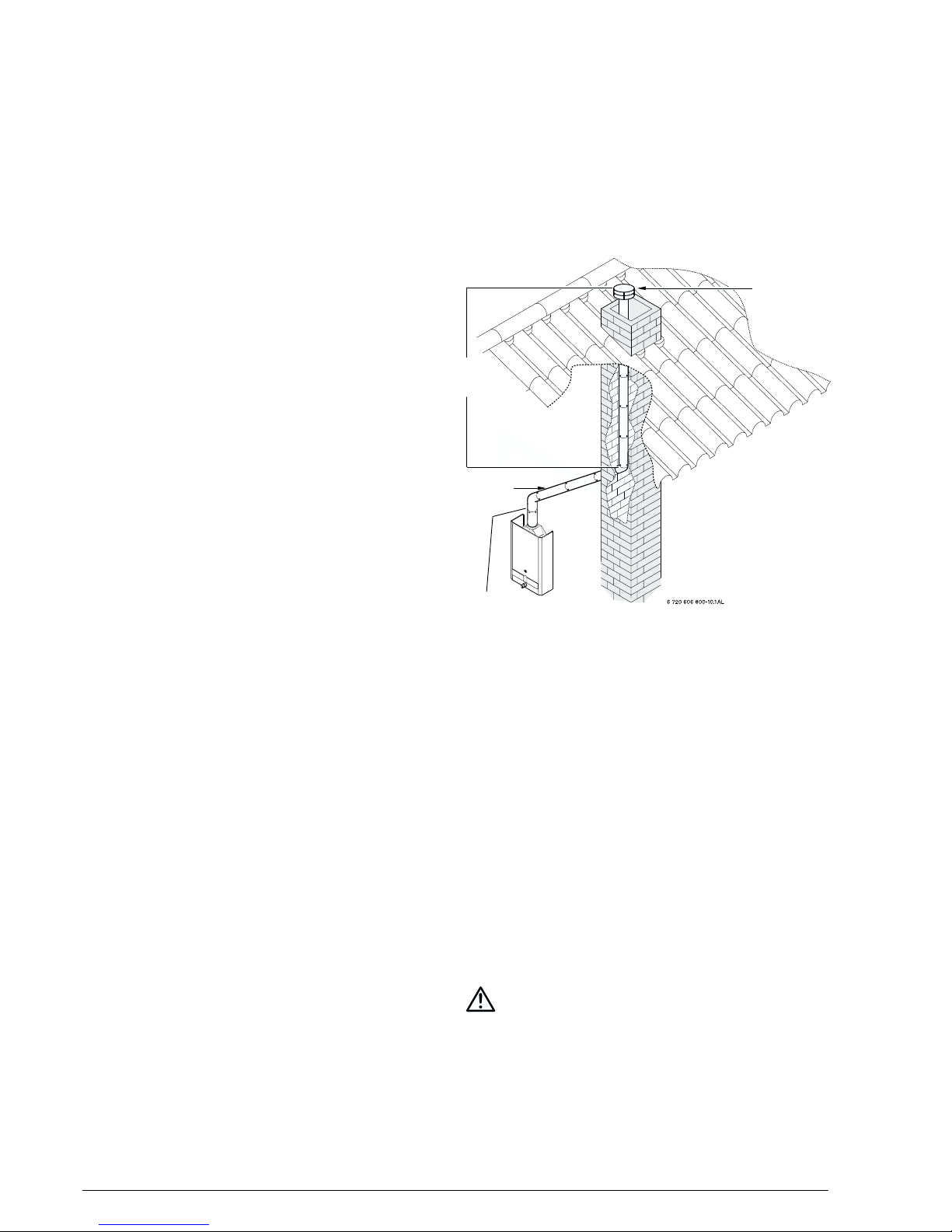
MASONRY CHIMNEYS
Gas vent
Vent
connector
Establish a one foot
rise before any elbows
Listed vent cap
Figure C
MASONRY CHIMNEY: Masonry chimneys shall be built and
installed in accordance with NFPS 211 or local codes. A
minimum 5” diameter gas vent pipe (metal double wall Type
B), or an approved clay flue liner or a listed chimney lining
system must be used when venting into a naturally drafting,
internal masonry chimney. 6 inch is required in elevations
greater than 2000 feet, see Fig. 4. Local codes may require
the use of both gas vent and an approved lining system
when venting into a masonry chimney. The Commonwealth
of Massachusetts requires the use of a listed liner. Lining
systems include approved clay flue lining, a listed chimney
lining system or other approved material that will resist
corrosion, erosion, softening, or cracking from exhaust flue
gases at temperatures up to 1800 degrees F. The lining
system must be listed for use with naturally drafting, draft
hood equipped gas appliances. Follow local codes and refer
to NFGC 54 and NFPA 58.
When connecting the water heater to a masonry chimney
the following connector guidelines must be followed for
safe and proper operation: An approved gas vent connector
must be attached to the top of the water heater and rise
vertically at least 12” before entering into an approved gas
vent connector elbow. Any gas vent section that is greater
than 45 degrees from the vertical is considered horizontal.
If a horizontal vent connector is to be used to connect the
vertical gas vent connector on the top of the water heater
to the masonry chimney, that approved horizontal gas vent
connector must be kept as short as possible and must be
sloped upwards at least ¼” per foot of its length. This
connector must be supported throughout its horizontal length.
This horizontal gas vent connection may be no greater than
75% of the total vertical gas flue vent within the chimney.
Also, an approved thimble or collar must be used when
penetrating a masonry chimney.
A) Existing INTERIOR Masonry Chimney
The metal gas vent pipe should be permanently mounted
inside the masonry chimney. Double wall Type B gas vent is
recommended. The masonry chimney may have to be tile
or metal lined before the insertion of the gas vent pipe;
check local codes for clarification. The lining material must
be listed for use only with naturally drafting, draft hood
equipped gas appliances. Follow manufactures instructions
for installation of listed lining material. You may not vent any
other fuel burning appliances into any free space remaining
in the chimney. The minimum vertical gas vent length within
the masonry chimney should be no less than 5 ft (1.5 m);
the vent terminator should extend at least 3 feet (0.9 m)
above where the chimney meets the roofline and at least 2
feet (0.6 m) higher than any vertical wall or similar obstruction
within 10 feet (3.1 m). The top of the gas vent should have
an approved vent terminator. See Figure C.
B) Tile Lined INTERIOR Masonry Chimney
The masonry chimney must have an approved liner, ceramic
tile, clay or metal. The masonry chimney must be able to
accommodate the spent fuel gasses; consult a venting
HVAC contractor for chimney capacity. A common venting
like-fuel appliance into this lined masonry chimney is
permissible. The chimney’s diameter must be large enough
to adequately draft the spent fuel gasses. A venting HVAC
contractor will be required to spec a chimney system. The
minimum vertical chimney length should be no less than 5
ft (1.5 m); the termination point should extend at least 3
feet (0.9 m) above where the chimney meets the roofline
and at least 2 feet (0.6 m) higher than any vertical wall or
similar obstruction within 10 feet (3.1 m). See Figure C.
C) EXTERIOR masonry Chimney
Refer to the National Fuel Gas Code and consult a local
venting HVAC contractor.
 Loading...