


Gas Heaters
GWH 10-2 G.. / GWH 13-2 G.. / GWH 16-2 G..
6 720 608 992 (2011/12) AU
en Installation Manual and Operating Instructions
Read installation manual prior to installation of this unit! Read user manual before putting this unit in operation!
Observe the warnings in the manuals!
The installation room must fulfill the ventilation requirements!
Installation by an authorised person only!

2 | Table of contents
Table of contents
1 Key to symbols and safety instructions . . . . . . . |
3 |
10 |
Water quality . . . . . . . . . . . . . . . . . . . . . . . . . . |
20 |
||
1.1 |
Explanation of symbols . . . . . . . . . . . . . . . . |
3 |
|
|
|
|
1.2 |
Safety information |
3 |
|
|
|
|
11 |
Warranty details |
21 |
||||
|
|
|
||||
2 Technical Characteristics and Dimensions . . . . . 4
2.1 General Description . . . . . . . . . . . . . . . . . . 4 2.2 Explanation of Model Code . . . . . . . . . . . . . 4 2.3 Package contents . . . . . . . . . . . . . . . . . . . . 4 2.4 Description of the heater . . . . . . . . . . . . . . 4 2.5 Dimensions . . . . . . . . . . . . . . . . . . . . . . . . . 5 2.6 Functional diagram of the heater . . . . . . . . 6 2.7 Electrical diagram . . . . . . . . . . . . . . . . . . . . 7 2.8 Function . . . . . . . . . . . . . . . . . . . . . . . . . . . 7 2.9 Technical characteristics . . . . . . . . . . . . . . 8
3 Regulations . . . . . . . . . . . . . . . . . . . . . . . . . . . . . . 9
4 Installation . . . . . . . . . . . . . . . . . . . . . . . . . . . . . 10
4.1 Important information . . . . . . . . . . . . . . . 10
4.2Selection of the place of installation . . . . 10
4.3 Heater mounting . . . . . . . . . . . . . . . . . . . . 11 4.4 Water connection . . . . . . . . . . . . . . . . . . . 11 4.5 Hydrogenerator operation . . . . . . . . . . . . 11 4.6 Pressure Relief . . . . . . . . . . . . . . . . . . . . . 12 4.7 Gas connection . . . . . . . . . . . . . . . . . . . . . 12 4.8 Testing . . . . . . . . . . . . . . . . . . . . . . . . . . . 12
5 Operating instructions . . . . . . . . . . . . . . . . . . . . 13
5.1 Digital display - description . . . . . . . . . . . 13 5.2 Before starting up the heater . . . . . . . . . . 13 5.3 Turning the heater on and off . . . . . . . . . . 13 5.4 Water flow . . . . . . . . . . . . . . . . . . . . . . . . 13 5.5 Gas adjustment . . . . . . . . . . . . . . . . . . . . . 14 5.6 Temperature/flow adjustment . . . . . . . . . 14 5.7 Draining the appliance . . . . . . . . . . . . . . . 14
6 Commissioning . . . . . . . . . . . . . . . . . . . . . . . . . . 15
6.1 Inlet pressure adjustment . . . . . . . . . . . . . 15 6.2 Burner pressure adjustment . . . . . . . . . . . 15
6.3Conversion to a different type of gas . . . . 15
7 Maintenance . . . . . . . . . . . . . . . . . . . . . . . . . . . . 16
7.1 Flue gas safety device . . . . . . . . . . . . . . . . 16
8 Problems . . . . . . . . . . . . . . . . . . . . . . . . . . . . . . . 17
8.1 Problem/cause/solution . . . . . . . . . . . . . . 17
9 Environmental protection . . . . . . . . . . . . . . . . . 19
6 720 608 992 (2011/12)
Key to symbols and safety instructions | 3
1 Key to symbols and safety instructions
1.1Explanation of symbols
Warnings
Warnings in this document are framed and identified by a warning triangle which is printed on a grey background.
Electrical hazards are identified by a lightning symbol surrounded by a warning triangle.
Keywords indicate the seriousness of the hazard in terms of the consequences of not following the safety instructions.
•NOTICE indicates that material damage may occur.
•CAUTION indicates that minor to medium injury may occur.
•WARNING indicates that serious injury may occur.
•DANGER indicates possible risk to life.
Important information
Important information in cases where there is no risk of personal injury or material losses is identified by the symbol shown on the left. It is bordered by horizontal lines above and below the text.
Additional symbols
Symbol Meaning
B |
a step in an action sequence |
Æa reference to a related part in the document or to other related documents
•a list entry
–a list entry (second level)
Table 1
1.2Safety information
If you smell gas:
B Close the gas supply valve.
B Open the windows.
BDo not operate any electrical appliances or switches (on/off).
B Extinguish other sources of ignition.
BGo to a different location and call the gas supplier or an authorised technician.
If you smell combustion gases:
B Turn off the heater.
B Open doors and windows.
B Notify an authorised technician.
Assembly, modifications
BThe assembly and modifications to the heater can only be performed by an authorised installer.
BDo not modify the pipes which conduct combustion gases.
B Do not close or reduce air circulation vents.
Maintenance
BWe recommend the system be serviced regularly to ensure it functions reliably and safely.
BThe installer is responsible for the safety and environmental compatibility of the installation.
B The heater should be serviced annually. B Only original spare parts must be used.
Explosive and highly inflammable material
BDo not store or use inflammable material (paper, solvents, paints, etc) near the heater.
Combustion air and surrounding air
BTo avoid corrosion, the combustion air and surrounding air must be free from harmful substances (e.g. halogenated hydrocarbons which contain chlorine and fluorine compounds).
BDo not spray pressure pack or use chemicals around the heater
Information to the customer
B Inform the customer about how to operate the heater.
BThis appliance is not intended for use by persons (including children) with reduced physical sensory or mental capabilities.
Children should be supervised to ensure they do not play with the appliance.
BCaution customers against performing modifications or repairs themselves.
To be installed and serviced only by an authorised person
The “authorised installing person” is responsible for: B Correct commissioning of this appliance.
BEnsuring the appliance performs to the specifications stated on the rating label.
BDemonstrating the operation of the appliance to the customer before leaving.
B Handing these instructions to customer.
THIS APPLIANCE IS NOT FOR USE AS A POOL OR SPA POOL HEATER.
THIS APPLIANCE IS ONLY TO BE INSTALLED INDOORS.
6 720 608 992 (2011/12)

4 | Technical Characteristics and Dimensions
2 Technical Characteristics and Dimensions
2.1General Description
|
|
Model |
GWH 10/13/16 -2 G.. |
|
|
Category |
CONTINUOUS FLOW |
|
|
Type |
INTERNAL |
|
|
Table 2 |
|
•Gas flow adjustment proportional to the water flow to maintain a constant temperature.
•Safety devices:
–Ionisation probe to check for accidental extinction of the burner flame
–Flue gas safety device which turns off the heater in cases where the evacuation of flue gases is inadequate
–Overtemperature switch which prevents overheating of the heat exchanger.
2.2Explanation of Model Code
Type |
l/min |
Series |
Ignition |
Gas Types |
|
|
|
|
|
GWH |
10 |
2 |
G |
NG / LP gas |
|
|
|
|
|
GWH |
13 |
2 |
G |
NG / LP gas |
|
|
|
|
|
GWH |
16 |
2 |
G |
NG / LP gas |
|
|
|
|
|
Table 3
2.3Package contents
•Gas heater
•Fixing Brackets
•flexible water pipes
•Gas regulator
•Heater documentation
2.4Description of the heater
Designed for convenience, the heater is ready to operate by simply pressing a switch.
•Heater for wall-mounting
•Ignition by electronic device triggered when the water valve opens
•Hydrodynamic generator produces sufficient energy to ignite and control the heater.
•Gauge to display temperature, burner operation and error codes
•Temperature sensor to monitor the water temperature at the heater outlet
•Available in Natural gas or LP gas
•Temporary pilot burner which only functions during the period between the opening of the water valve and the ignition of the main burner
•Water valve made of fibreglass-reinforced polyamide, and is 100% recyclable
•Automatic control of the water flow to allow for variable water supply pressure.
6 720 608 992 (2011/12)
Technical Characteristics and Dimensions | 5
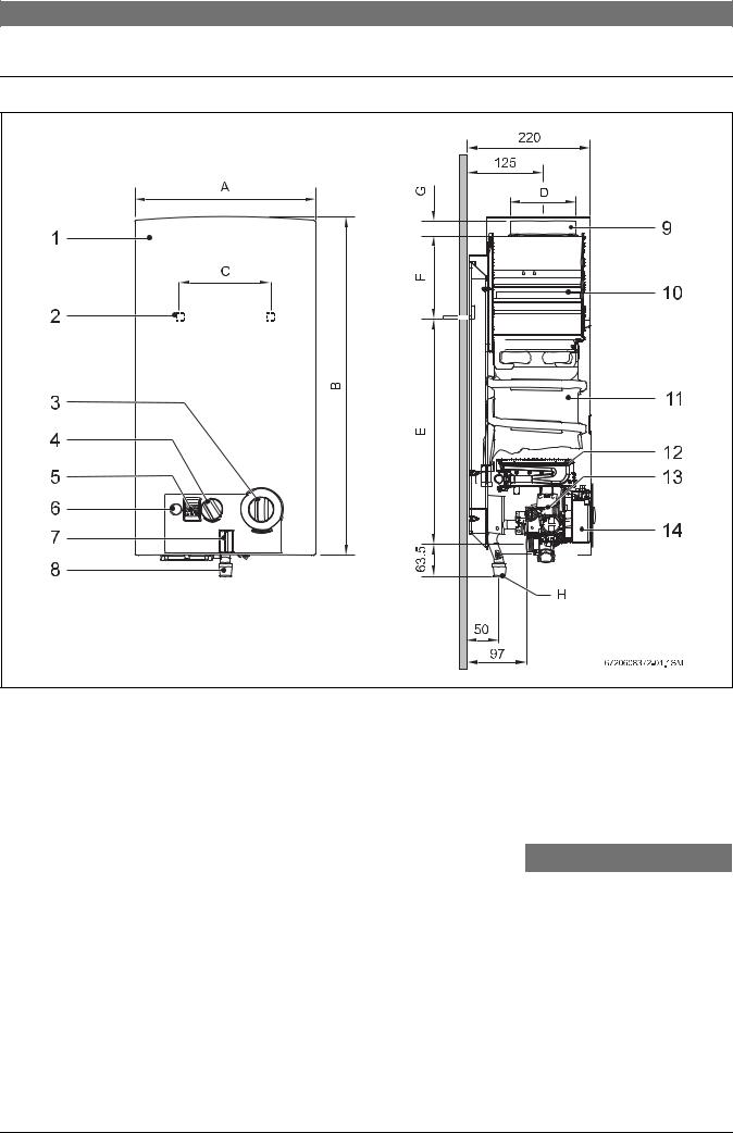
2.5Dimensions
Fig. 1
1 |
Front cover |
|
|
|
|
|
8 |
Gas connection |
|
|
|
||||
2 |
Opening in rear panel for mounting on the wall |
|
9 |
Connection collar for flue |
|
||||||||||
3 |
Temperature/volume selector |
|
|
|
10 |
Draught diverter |
|
|
|
||||||
4 |
Gas adjustment |
|
|
|
|
|
11 |
Copper Heat exchanger |
|
|
|
||||
5 |
Digital display |
|
|
|
|
|
12 |
Burner |
|
|
|
|
|
||
6 |
Switch/LED - Low water pressure indicator |
|
13 |
Gas valve |
|
|
|
|
|
||||||
7 |
LED - Burner status check |
|
|
|
14 |
Ignition unit |
|
|
|
|
|
||||
|
|
|
|
|
|
|
|
|
|
|
|
|
H (Ø) |
|
|
|
Dimensions |
|
|
|
|
|
|
|
|
|
|
|
|||
|
|
|
|
|
|
|
|
|
|
|
|
|
|
||
|
(mm) |
A |
B |
C |
D |
E |
F |
G |
|
Natural gas |
LP gas |
||||
|
|
|
|
|
|
|
|
|
|
|
|
|
|||
|
|
|
|
|
|
|
|
|
|
|
|
|
|
|
|
|
GWH10... |
|
310 |
|
580 |
228 |
115 |
463 |
60 |
|
25 |
|
20 |
|
15 |
|
|
|
|
|
|
|
|
|
|
|
|
|
|
|
|
|
GWH13... |
|
350 |
|
655 |
228 |
140 |
510 |
95 |
|
30 |
|
20 |
|
15 |
|
|
|
|
|
|
|
|
|
|
|
|
|
|
|
|
|
GWH16... |
|
425 |
|
655 |
334 |
140 |
540 |
65 |
|
30 |
|
20 |
|
15 |
|
|
|
|
|
|
|
|
|
|
|
|
|
|
|
|
Table 4 Dimensions |
|
|
|
|
|
|
|
|
|
|
|
|
|
||
6 720 608 992 (2011/12)

6 | Technical Characteristics and Dimensions
2.6Functional diagram of the heater
1 2 3 4 5
32
31 


|
|
|
|
|
6 |
|
|
30 |
|
|
15 |
|
|
29 |
|
|
7a |
|
|
28 |
|
|
8 |
|
|
|
|
|
|
|
|
27 |
|
|
33 |
|
|
26 |
|
|
10 |
|
|
|
|
|
9 |
|
|
25 |
|
|
11 |
|
|
24 |
|
|
12 |
|
|
|
|
|
|
|
|
|
|
|
13 |
|
|
23 |
|
|
14 |
|
|
|
|
|
|
|
|
22 |
|
|
|
|
|
|
|
|
16 |
|
|
21 7b 20 19 |
18 |
17 |
6720608992-05.1V |
Fig. 2 |
Functional diagram |
|
|
|
|
1 |
Pilot burner |
17 |
Diaphragm |
|
|
2 |
Ignition Electrode |
18 |
Main gas valve |
|
|
3 |
Ionisation probe |
19 |
Maximum gas adjusting screw |
||
4 |
Heat exchanger |
20 |
Gas supply pipe |
|
|
5 |
Main burner |
21 |
Gas filter |
|
|
6 |
Injector |
22 |
Hot water pipe |
|
|
7a |
Burner pressure test point |
23 |
Ignition unit |
|
|
7b |
Gas inlet pressure test point |
24 |
Temperature sensor |
|
|
8 |
Slow ignition valve |
25 |
Servo valve |
|
|
9 |
Venturi |
26 |
Power selector |
|
|
10 |
Temperature/volume selector |
27 |
Gas valve |
|
|
11 |
Water valve |
28 |
Pilot valve |
|
|
12 |
Plunger |
29 |
Pilot injector |
|
|
13 |
Water flow regulator |
30 |
Pilot gas pipe |
|
|
14 |
Water filter |
31 |
Overtemperature switch |
|
|
15 |
Hydrogenerator |
32 |
Flue gas safety device |
|
|
16 |
Cold water pipe |
33 |
Relief Valve/Drain screw |
|
|
6 720 608 992 (2011/12)
Technical Characteristics and Dimensions | 7
2.7Electrical diagram
|
|
|
|
|
|
|
|
|
|
|
|
|
|
|
|
|
|
|
|
|
|
|
|
|
|
|
|
|
|
|
|
|
|
|
|
|
|
|
|
|
|
|
|
|
|
|
|
|
|
|
|
|
|
|
|
|
|
|
|
|
|
|
|
|
|
|
|
|
|
|
|
|
|
|
|
|
|
|
|
|
|
|
|
|
|
|
|
|
|
|
|
|
|
|
|
|
|
|
|
|
|
|
|
|
|
|
|
|
|
|
|
|
|
|
|
|
|
|
|
|
|
|
|
|
|
|
|
|
|
|
|
|
|
|
|
|
|
|
|
|
|
|
|
|
|
|
|
|
|
|
|
|
|
|
|
|
|
|
|
|
|
|
|
|
|
|
|
|
|
|
|
|
|
|
|
|
|
|
|
|
|
|
|
|
|
|
|
|
|
|
|
|
|
|
|
|
|
|
|
|
|
|
|
|
|
|
|
|
|
|
|
|
|
|
|
|
|
|
|
|
|
|
|
|
|
|
|
|
|
|
|
|
|
|
|
|
|
|
|
|
|
|
|
|
|
|
|
|
|
|
|
|
|
|
|
|
|
|
|
|
|
|
|
|
|
|
|
|
|
|
|
|
|
|
|
|
|
|
|
|
|
|
|
|
|
|
|
|
|
|
|
|
|
|
|
|
|
|
|
|
|
|
|
|
|
|
|
|
|
|
|
|
|
|
|
|
|
|
|
|
|
|
|
|
|
|
|
|
|
|
|
|
|
|
|
|
|
|
|
|
|
|
|
|
|
|
|
|
|
|
|
|
|
|
|
|
|
|
|
|
|
|
|
|
|
|
|
|
|
|
|
|
|
|
|
|
|
|
|
|
|
|
|
|
|
|
|
|
|
|
|
|
|
|
|
|
|
|
|
|
|
|
|
|
|
|
|
|
|
|
|
|
|
|
|
|
|
|
|
|
|
|
|
|
|
|
|
|
|
|
|
|
|
|
|
|
|
|
|
|
|
|
|
|
|
|
|
|
|
|
|
|
|
|
|
|
|
|
|
|
|
|
|
|
|
|
|
|
|
|
|
|
|
|
|
|
|
|
|
|
|
|
|
|
|
|
|
|
|
|
|
|
|
|
|
|
|
|
|
|
|
|
|
|
|
|
|
|
|
|
|
|
|
|
|
|
|
|
|
|
|
|
|
|
|
|
|
|
|
|
|
|
|
|
|
|
|
|
|
|
|
|
|
|
|
|
|
|
|
|
|
|
|
|
|
|
|
|
|
|
|
|
|
|
|
|
|
|
|
|
|
|
|
|
|
|
|
|
|
|
|
|
|
|
|
|
|
|
|
|
|
|
|
|
|
|
|
|
|
|
|
|
|
|
|
|
|
|
|
|
|
|
|
|
|
|
|
|
|
|
|
|
|
|
|
|
|
|
|
|
|
|
|
|
|
|
|
|
|
|
|
|
|
|
|
|
|
|
|
|
|
|
|
|
|
|
|
|
|
|
|
|
|
|
|
|
|
|
|
|
|
|
|
|
|
|
|
|
|
|
|
|
|
|
|
|
|
|
|
|
|
|
|
|
|
|
|
|
|
|
|
|
|
|
|
|
|
|
|
|
|
|
|
|
|
|
|
|
|
|
|
|
|
|
|
|
|
|
|
|
|
|
|
|
|
|
|
|
|
|
|
|
|
|
|
|
|
|
|
|
|
|
|
|
|
|
|
|
|
|
|
|
|
|
|
|
|
|
|
|
|
|
|
|
|
|
|
|
|
|
|
|
|
|
|
|
|
|
|
|
|
|
|
|
|
|
|
|
|
|
|
|
|
|
|
|
|
|
|
|
|
|
|
|
|
|
|
|
|
|
|
|
|
|
|
|
|
|
|
|
|
|
|
|
|
|
|
|
|
|
|
|
|
|
|
|
|
|
|
|
|
|
|
|
|
|
|
|
|
|
|
|
|
|
|
|
|
|
|
|
|
|
|
|
|
|
|
|
|
|
|
|
|
|
|
|
|
|
|
|
|
|
|
|
|
|
|
|
|
|
|
|
|
|
|
|
|
|
|
|
|
|
|
|
|
|
|
|
|
|
|
|
|
|
|
|
|
|
|
|
|
|
|
|
|
|
|
|
|
|
|
|
|
|
|
|
|
|
|
|
|
|
|
|
|
|
|
|
|
|
|
|
|
|
|
|
|
|
|
|
|
|
|
|
|
|
|
|
|
|
|
|
|
|
|
|
|
|
|
|
|
|
|
|
|
|
|
|
|
|
|
|
|
|
|
|
|
|
|
|
|
|
|
|
|
|
|
|
|
|
|
|
|
|
|
|
|
|
|
|
|
|
|
|
|
|
|
|
|
|
|
|
|
|
|
|
|
|
|
|
|
|
|
|
|
|
|
|
|
|
|
|
|
|
|
|
|
|
|
|
|
|
|
|
|
|
|
|
|
|
|
|
|
|
|
|
|
|
|
|
|
|
|
|
|
|
|
|
|
|
|
|
|
|
|
|
|
|
|
|
|
|
|
|
|
|
|
|
|
|
|
|
|
|
|
|
|
|
|
|
|
|
|
|
|
|
|
|
|
|
|
|
|
|
|
|
|
|
|
|
|
|
|
|
|
|
|
|
|
|
|
|
|
|
|
|
|
|
|
|
|
|
|
|
|
|
|
|
|
|
|
|
|
|
|
|
|
|
|
|
|
|
|
|
|
|
|
|
|
|
|
|
|
|
|
|
|
|
|
|
|
|
|
|
|
|
|
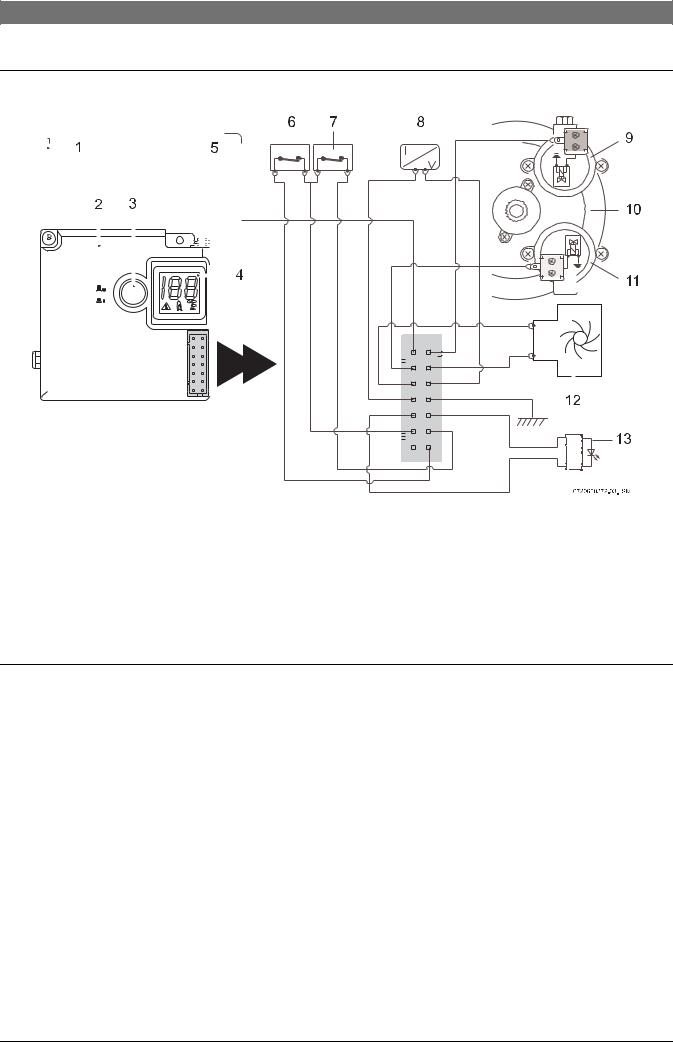
Fig. 3 |
|
Electrical diagram |
|
|
|
|
|
|
|
|
|
|
|
|
|
|
|
|
|
|
|
|
|
|
|
||||||||||||||||
1 |
Ignition electrode |
8 |
Temperature sensor |
|
|
|
|
|
|
|
|
|
|
||||||||||||||||||||||||||||
2 |
Ignition unit |
9 |
Pilot solenoid (Normally Closed) |
|
|
|
|
|
|
|
|
|
|
||||||||||||||||||||||||||||
3 |
Switch/LED - Low water pressure indicator |
10 |
Diaphragm valve |
|
|
|
|
|
|
|
|
|
|
||||||||||||||||||||||||||||
4 |
Digital display |
11 |
Main Solenoid (Normally Open) |
|
|
|
|
|
|
|
|
|
|
||||||||||||||||||||||||||||
5 |
Ionisation probe |
12 |
Hydrogenerator |
|
|
|
|
|
|
|
|
|
|
||||||||||||||||||||||||||||
6 |
Flue gas safety device |
13 |
LED - Burner status check |
|
|
|
|
|
|
|
|
|
|
||||||||||||||||||||||||||||
7 |
Overtemperature switch |
|
|
|
|
|
|
|
|
|
|
|
|
|
|
|
|
|
|
|
|
|
|
|
|||||||||||||||||
2.8Function
This gas heater is equipped with automatic electronic ignition to simplify operation.
B To activate, just turn on the switch (Fig. 8).
After this, automatic ignition occurs whenever a hot water tap is opened. First, the pilot burner is lit and approximately four seconds later the main burner ignites. The pilot burner flame is extinguished after the main burner lights.
This is a way of saving a great amount of energy as the pilot burner only operates for the minimum necessary time to ignite the main burner.
6 720 608 992 (2011/12)

8 | Technical Characteristics and Dimensions
2.9 |
Technical characteristics |
|
|
|
|
|
|
|
|
|
|
|
|
Technical characteristics |
Units |
GWH10 |
GWH13 |
GWH16 |
||
|
|
|
|
|
|
|
Gas Consumption |
|
|
|
|
||
|
|
|
|
|
|
|
Nominal Gas Consumption |
|
MJ |
79 |
100 (NG) |
127 |
|
|
|
|||||
|
97 (LP gas) |
|||||
|
|
|
|
|
|
|
|
|
|
|
|
|
|
Supply pressure |
|
|
|
|
||
|
|
|
|
|
||
Natural gas H |
|
kPa |
1.13 |
1.13 |
1.13 |
|
|
|
|
|
|
|
|
LP gas |
|
kPa |
2.75 |
2.75 |
2.75 |
|
|
|
|
|
|
|
|
Number of injectors |
|
|
12 |
14 |
18 |
|
|
|
|
|
|
|
|
Water data |
|
|
|
|
||
|
|
|
|
|
||
Maximum permissible pressure |
|
kPa |
1000 |
1000 |
1000 |
|
|
|
|
|
|
|
|
Temperature selector in fully clockwise position |
|
|
|
|
||
|
|
|
|
|
||
Temperature rise |
|
°C |
50 |
50 |
50 |
|
|
|
|
|
|
|
|
Flow range |
|
l/min |
2.2 - 4.6 |
2.2 - 6.2 |
2.2 - 8.6 |
|
|
|
|
|
|
|
|
Minimum operating pressure |
|
kPa |
35 |
35 |
50 |
|
|
|
|
|
|
|
|
Minimum pressure for maximum flow |
|
kPa |
50 |
60 |
80 |
|
|
|
|
|
|
|
|
Temperature selector in fully anti-clockwise position |
|
|
|
|
||
|
|
|
|
|
||
Temperature rise |
|
°C |
25 |
25 |
25 |
|
|
|
|
|
|
|
|
Flow range |
|
l/min |
4 - 10 |
4 - 13 |
4 - 15 |
|
|
|
|
|
|
|
|
Minimum operating pressure |
|
kPa |
45 |
45 |
50 |
|
|
|
|
|
|
|
|
Minimum pressure for maximum flow |
|
kPa |
100 |
140 |
170 |
|
|
|
|
|
|
|
|
Table 5
6 720 608 992 (2011/12)
 Loading...