


Robert Bosch GmbH
Power Tools Division
70745 Leinfelden-Echterdingen
Germany
www.bosch-pt.com
1 609 929 S09 (2009.01) T / 369 XXX
GTL 3 Professional
de |
Originalbetriebsanleitung |
cs |
Původní návod k používání |
en |
Original instructions |
sk |
Pôvodný návod na použitie |
fr |
Notice originale |
hu |
Eredeti használati utasítás |
es |
Manual original |
ru |
Оригинальное руководство |
pt |
Manual original |
|
по эксплуатации |
it |
Istruzioni originali |
uk Оригінальна інструкція з |
|
nl |
Oorspronkelijke gebruiks- |
|
експлуатації |
|
aanwijzing |
ro |
Instrucţiuni originale |
da Original brugsanvisning |
bg |
Оригинална инструкция |
|
sv |
Bruksanvisning i original |
sr |
Originalno uputstvo za rad |
no |
Original driftsinstruks |
sl |
Izvirna navodila |
fi |
Alkuperäiset ohjeet |
hr |
Originalne upute za rad |
el |
Πρωτότυπο οδηγιών χρήσης |
et |
Algupärane kasutusjuhend |
tr |
Orijinal işletme talimat |
lv |
Instrukcijas oriģinālvalodā |
pl |
Instrukcja oryginalna |
lt |
Originali instrukcija |
cn tw
ko
th
id Petunjuk-Petunjuk untuk
Penggunaan Orisinal
vi BΩng hõëng dÿn nguy›n bΩn
ar ΔϴϠλϷ ϞϴϐθΘϟ ΕΎϤϴϠόΗ fa ̶Ϡλ έΎ̯ ίήσ ̵ΎϤϨϫέ

2 |
Deutsch . . . . . . . . . . . . . . . . . . . . . . |
. . . Seite |
7 |
English . . . . . . . . . . . . . . . . . . . . . . . |
. . . .Page |
18 |
Français . . . . . . . . . . . . . . . . . . . . . . |
. . . .Page |
31 |
Español. . . . . . . . . . . . . . . . . . . . . . . |
. . Página |
42 |
Português . . . . . . . . . . . . . . . . . . . . . |
. . Página |
53 |
Italiano . . . . . . . . . . . . . . . . . . . . . . . |
. . Pagina |
64 |
Nederlands . . . . . . . . . . . . . . . . . . . . |
. . Pagina |
75 |
Dansk . . . . . . . . . . . . . . . . . . . . . . . . |
. . . . Side |
86 |
Svenska . . . . . . . . . . . . . . . . . . . . . . |
. . . . Sida |
96 |
Norsk . . . . . . . . . . . . . . . . . . . . . . . . |
. . . . Side |
106 |
Suomi . . . . . . . . . . . . . . . . . . . . . . . . |
. . . . Sivu |
116 |
Ελληνικά . . . . . . . . . . . . . . . . . . . . . . |
. . . Σελίδα |
126 |
Türkçe. . . . . . . . . . . . . . . . . . . . . . . . |
. . . Sayfa |
137 |
Polski . . . . . . . . . . . . . . . . . . . . . . . . |
. . Strona |
147 |
Česky . . . . . . . . . . . . . . . . . . . . . . . . |
. . Strana |
158 |
Slovensky . . . . . . . . . . . . . . . . . . . . . |
. . Strana |
168 |
Magyar . . . . . . . . . . . . . . . . . . . . . . . |
. . . Oldal |
178 |
Русский . . . . . . . . . . . . . . . . . . . . . . |
Страница 188 |
|
Українська . . . . . . . . . . . . . . . . . . . . |
Сторінка |
199 |
Română . . . . . . . . . . . . . . . . . . . . . . |
. . Pagina 210 |
|
Български. . . . . . . . . . . . . . . . . . . . . |
Страница |
221 |
Srpski . . . . . . . . . . . . . . . . . . . . . . . . |
. . Strana |
232 |
Slovensko . . . . . . . . . . . . . . . . . . . . . |
. . . Stran |
242 |
Hrvatski . . . . . . . . . . . . . . . . . . . . . . |
. Stranica |
252 |
Eesti . . . . . . . . . . . . . . . . . . . . . . . . . |
Lehekülg |
262 |
Latviešu . . . . . . . . . . . . . . . . . . . . . . |
. Lappuse |
272 |
Lietuviškai . . . . . . . . . . . . . . . . . . . . |
. Puslapis |
282 |
. . . . . . . . . . . . . . . . . . . . . . . . . . |
. . . . . . 292 |
|
. . . . . . . . . . . . . . . . . . . . . . . . . . |
. . . . . . 301 |
|
. . . . . . . . . . . . . . . . . . . . . . . . |
. . . . . . 310 |
|
. . . . . . . . . . . . . . . . . . . . . . . |
. . . . . |
319 |
Bahasa Indonesia . . . . . . . . . . . . . . . |
.Halaman |
329 |
Tiøng Vi·t . . . . . . . . . . . . . . . . . . . . . |
. . . Trang |
340 |
. . . . . . . . . . . . . . . . . . . . . . . . . |
. . . ΔΤϔλ 350 |
|
vÝ—U . . . . . . . . . . . . . . . . . . . . . . . |
. . . ϪΤϔλ 359 |
|
1 609 929 S09 | (15.10.08) |
Bosch Power Tools |

3 | |
|
|
|
|
3 |
|
|
1 |
IEC |
|
|
<160825- |
|
|
mW, |
1:200 |
|
|
635 |
7- |
2 |
|
nm03 |
|
|
|
|
|
1 |
1 |
|
|
9 |
4 |
|
|
||
|
|
5 |
6 |
|
|
7 |
|
|
8 |
|
3 |
|
8 |
|
|
|
|
Bosch Power Tools |
|
1 609 929 S09 | (15.10.08) |
4 | |
|
A |
|
|
90˚ |
0˚ |
|
B |
90˚ |
45˚ |
|
0˚ |
|
C |
90˚ |
|
|
|
45˚ |
|
0˚ |
1 609 929 S09 | (15.10.08) |
Bosch Power Tools |

5 | |
|
|
D |
0˚ |
45˚ |
|
|
90˚ |
E |
0˚ |
45˚ |
|
||
|
|
90˚ |
F |
|
P |
P |
Bosch Power Tools |
1 609 929 S09 | (15.10.08) |
6 | |
|
10 |
11 |
1 609 203 X74 |
12 |
|
|
|
1 609 203 X75 |
|
Prof |
|
essi |
|
onal |
|
13 |
|
2 607 990 031 |
|
14 |
|
2 607 001 301 |
1 609 929 S09 | (15.10.08) |
Bosch Power Tools |

Sicherheitshinweise
Sämtliche Anweisungen sind zu lesen, um mit dem Messwerkzeug gefahrlos und sicher zu arbeiten. Machen Sie Warnschilder am Messwerkzeug niemals unkenntlich. BEWAHREN SIE DIESE ANWEISUNGEN GUT AUF.
fVorsicht – wenn andere als die hier angegebenen Bedienungsoder Justiereinrichtungen benutzt oder andere Verfahrensweisen ausgeführt werden, kann dies zu gefährlicher Strahlungsexposition führen.
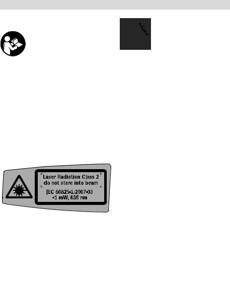
fDas Messwerkzeug wird mit einem Warnschild in englischer Sprache ausgeliefert (in der Darstellung des Messwerkzeugs auf der Grafikseite mit Nummer 2 gekennzeichnet).
fÜberkleben Sie das englische Warnschild vor der ersten Inbetriebnahme mit dem mitgelieferten Aufkleber in Ihrer Landessprache.
Deutsch | 7
Richten Sie den Laserstrahl nicht auf Personen oder Tiere und blicken Sie nicht selbst in den Laserstrahl. Dieses Messwerkzeug erzeugt Laserstrahlung der Laserklasse 2 gemäß IEC 60825-1. Dadurch können Sie Personen blenden.
fVerwenden Sie die Laser-Sichtbrille nicht als Schutzbrille. Die Laser-Sicht- brille dient zum besseren Erkennen des Laserstrahls, sie schützt jedoch nicht vor der Laserstrahlung.
fVerwenden Sie die Laser-Sichtbrille nicht als Sonnenbrille oder im Straßenverkehr. Die Laser-Sichtbrille
bietet keinen vollständigen UV-Schutz und vermindert die Farbwahrnehmung.
fLassen Sie das Messwerkzeug von qualifiziertem Fachpersonal und nur mit Ori- ginal-Ersatzteilen reparieren. Damit wird sichergestellt, dass die Sicherheit des Messwerkzeuges erhalten bleibt.
fLassen Sie Kinder das Laser-Messwerk- zeug nicht unbeaufsichtigt benutzen. Sie könnten unbeabsichtigt Personen blenden.
Bosch Power Tools |
1 609 929 S09 | (15.10.08) |

8 | Deutsch
Bringen Sie das Messwerkzeug und die Deckenmessplatte 14 nicht in die Nähe von
Herzschrittmachern. Durch die Magnete 4 an der Unterseite des Messwerkzeugs sowie
durch die Magnete an der Deckenmessplatte wird ein Feld erzeugt, das die Funktion von Herzschrittmachern beeinträchtigen kann.
fHalten Sie das Messwerkzeug und die Deckenmessplatte 14 fern von magnetischen Datenträgern und magnetisch empfindlichen Geräten. Durch die Wirkung der Magnete 4 an der Unterseite des Messwerkzeugs sowie der Magnete an der Deckenmessplatte kann es zu irreversiblen Datenverlusten kommen.
Funktionsbeschreibung
Bitte klappen Sie die Ausklappseite mit der Darstellung des Messwerkzeugs auf, und lassen Sie diese Seite aufgeklappt, während Sie die Betriebsanleitung lesen.
Bestimmungsgemäßer Gebrauch
Das Messwerkzeug ist bestimmt zum Ermitteln und Überprüfen von rechten Winkeln sowie zum Ausrichten von Fliesen im Winkel von 45° und 90°.
Abgebildete Komponenten
Die Nummerierung der abgebildeten Komponenten bezieht sich auf die Darstellung des Messwerkzeugs auf der Grafikseite.
1Austrittsöffnung Laserstrahlung
2Laser-Warnschild
3Ein-Aus-Taste
4Magnete
5Seriennummer
6Batteriefachdeckel
7Arretierung des Batteriefachdeckels
8Batterie-Anzeige
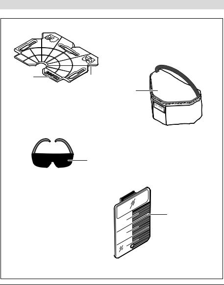
9Laser-Zieltafel
10Ausrichtplatte
11Aussparung an der Ausrichtplatte
12Schutztasche
13Laser-Sichtbrille*
14Deckenmessplatte*
*Abgebildetes oder beschriebenes Zubehör gehört nicht zum Standard-Lieferumfang. Das vollständige Zubehör finden Sie in unserem Zubehörprogramm.
1 609 929 S09 | (15.10.08) |
Bosch Power Tools |

|
Deutsch | 9 |
|
|
Technische Daten |
|
|
|
Fliesenlaser |
GTL 3 |
|
Professional |
Sachnummer |
3 601 K15 200 |
Arbeitsbereich (mit Laser-Zieltafel oder mit Deckenplatte) |
20 m1) |
Winkelgenauigkeit |
±0,2 mm/m2) |
Betriebstemperatur |
– 10 °C ... +50 °C |
Lagertemperatur |
– 20 °C ... +70 °C |
Relative Luftfeuchte max. |
90 % |
Laserklasse |
2 |
Lasertyp |
635 nm, <1 mW |
C6 |
1 |
Batterien |
4 x 1,5 V LR6 (AA) |
Betriebsdauer |
|
– mit 2 Laserlinien |
18 h |
– mit 3 Laserlinien |
12 h |
Abschaltautomatik nach ca. |
30 min |
Gewicht entsprechend EPTA-Procedure 01/2003 |
0,5 kg |
Maße |
156 x 102 x 98 mm |
Schutzart |
IP 54 (staubund |
|
spritzwassergeschützt) |
|
|
1)Der Arbeitsbereich kann durch ungünstige Umgebungsbedingungen (z.B. direkte Sonneneinstrahlung) verringert werden.
2)Die Winkelgenauigkeit zwischen der 45°-Laserlinie und der 90°-Laserlinie beträgt max. ±0,4 mm/m.
Bitte beachten Sie die Sachnummer auf dem Typenschild Ihres Messwerkzeugs, die Handelsbezeichnungen einzelner Messwerkzeuge können variieren.
Zur eindeutigen Identifizierung Ihres Messwerkzeugs dient die Seriennummer 5 auf dem Typenschild.
Bosch Power Tools |
1 609 929 S09 | (15.10.08) |

10 | Deutsch
Montage
Batterien einsetzen/wechseln
Für den Betrieb des Messwerkzeugs wird die Verwendung von Alkali-Mangan-Batterien empfohlen.
Zum Öffnen des Batteriefachdeckels 6 drücken Sie auf die Arretierung 7 und klappen den Batteriefachdeckel auf. Setzen Sie die Batterien ein. Achten Sie dabei auf die richtige Polung entsprechend der Darstellung auf der Innenseite des Batteriefachs.
Blinkt die Batterie-Anzeige 8, dann sind die Batterien schwach. Das Messwerkzeug kann nach dem ersten Blinken noch ca. 2 h betrieben werden.
Leuchtet die Batterie-Anzeige 8 konstant, sind keine Messungen mehr möglich. Das Messwerkzeug schaltet sich nach kurzer Zeit automatisch ab.
Ersetzen Sie immer alle Batterien gleichzeitig. Verwenden Sie nur Batterien eines Herstellers und mit gleicher Kapazität.
fNehmen Sie die Batterien aus dem Messwerkzeug, wenn Sie es längere Zeit nicht benutzen. Die Batterien können bei längerer Lagerung korrodieren und sich selbst entladen.
Betrieb
Inbetriebnahme
fSchützen Sie das Messwerkzeug vor Nässe und direkter Sonneneinstrahlung.
fSetzen Sie das Messwerkzeug keinen extremen Temperaturen oder Temperaturschwankungen aus. Lassen Sie es z.B. nicht längere Zeit im Auto liegen. Lassen Sie das Messwerkzeug bei größeren Temperaturschwankungen erst austemperieren, bevor Sie es in Betrieb nehmen. Bei extremen Temperaturen oder Temperaturschwankungen kann die Präzision des Messwerkzeugs beeinträchtigt werden.
fVermeiden Sie heftige Stöße oder Stürze des Messwerkzeuges. Nach starken äußeren Einwirkungen auf das Messwerkzeug sollten Sie vor dem Weiterarbeiten immer eine Genauigkeitsüberprüfung durchführen (siehe „Winkelgenauigkeit“, Seite 11).
Ein-/Ausschalten
Zum Einschalten des Messwerkzeugs drücken Sie einmal kurz die Ein-Aus-Taste 3. Das Messwerkzeug sendet sofort nach dem Einschalten die drei Laserlinien 0°, 45° und 90° aus den Austrittsöffnungen 1, außerdem leuchtet die Batterie-Anzeige 8 für 3 s.
fRichten Sie den Laserstrahl nicht auf Personen oder Tiere und blicken Sie nicht selbst in den Laserstrahl, auch nicht aus größerer Entfernung.
1 609 929 S09 | (15.10.08) |
Bosch Power Tools |
Beim zweiten Drücken auf die Ein-Aus-Taste 3 schaltet das Messwerkzeug vom 3-Linien- Betrieb auf den 2-Linien-Betrieb um: Es werden nur noch die 0°- und die 90°-Laserlinie angezeigt.
Zum Ausschalten des Messwerkzeugs drücken Sie ein drittes Mal auf die Ein-Aus-Taste 3.
Abschaltautomatik deaktivieren
Das Messwerkzeug schaltet sich nach 30 min Betriebsdauer automatisch ab.
Um die Abschaltautomatik zu deaktivieren, drücken Sie beim Einschalten des Messwerkzeugs 3 s lang auf die Ein-Aus-Taste 3. Ist die Abschaltautomatik deaktiviert, blinken die Laserlinien nach dem Einschalten kurz zur Bestätigung.
fLassen Sie das eingeschaltete Messwerkzeug nicht unbeaufsichtigt und schalten Sie das Messwerkzeug nach Gebrauch ab. Andere Personen könnten vom Laserstrahl geblendet werden.
Um die automatische Abschaltung zu aktivieren, schalten Sie das Messwerkzeug aus und durch kurzes Drücken auf die Ein-Aus-Taste 3 wieder ein. Nach dem Einschalten blinken die Laserlinien nicht.
Deutsch | 11
Winkelgenauigkeit
Genauigkeitseinflüsse
Den größten Einfluss übt die Umgebungstemperatur aus. Besonders vom Boden nach oben verlaufende Temperaturunterschiede können den Laserstrahl ablenken.
Stellen Sie deshalb das Messwerkzeug möglichst nah an der Arbeitsfläche auf und befestigen Sie es mit der Unterseite möglichst parallel zur Arbeitsfläche.
Neben äußeren Einflüssen können auch gerätespezifische Einflüsse (wie z.B. Stürze oder heftige Stöße) zu Abweichungen führen.
Überprüfen Sie deshalb vor jedem Arbeitsbeginn die Genauigkeit des Messwerkzeugs.
Winkelgenauigkeit überprüfen
Für die Überprüfung benötigen Sie eine freie Fläche von ca. 10 x 5 m auf festem, ebenem Untergrund.
Sollte das Messwerkzeug bei einer der Prüfungen die maximale Abweichung überschreiten, dann lassen Sie es von einem BoschKundendienst reparieren.
Bosch Power Tools |
1 609 929 S09 | (15.10.08) |

12 | Deutsch
Winkelgenauigkeit zwischen 0°- und 90°-Laserlinie überprüfen
–Stellen Sie das Messwerkzeug in eine der Ecken der Messfläche. Schalten Sie das Messwerkzeug ein und richten Sie es so aus, dass die 0°-Laserlinie entlang der langen Seite der Messfläche und die 90°-Laserlinie entlang der kurzen Seite der Messfläche verläuft.
| <![if ! IE]> <![endif]>5 m |
10 m |
–Markieren Sie den Kreuzungspunkt der Laserlinien auf dem Boden (Punkt I). Markieren Sie außerdem die Mitte der 0°-Laserlinie in 5 m Entfernung (Punkt II) und in 10 m Entfernung (Punkt III).
<![endif]> d
d
–Drehen Sie das Messwerkzeug so um 90°, dass die Mitte der 0°-Laserlinie durch Punkt IV verläuft.
Der Kreuzungspunkt der Laserlinien muss weiterhin auf Punkt II liegen.
–Markieren Sie die Mitte der 90°-Laserlinie in 5 m Entfernung als Punkt V möglichst nahe neben Punkt I.
–Die Differenz d der beiden Punkte V und I ergibt die tatsächliche Abweichung der 0°-Laserlinie und der 90°-Laserlinie vom rechten Winkel.
Auf der Messstrecke von 2 x 5 m = 10 m beträgt die maximal zulässige Abweichung: 10 m x ±0,2 mm/m = ±2 mm.
Die Differenz d zwischen den Punkten I und V darf folglich höchstens 2 mm betragen.
–Stellen Sie das Messwerkzeug (ohne es zu drehen) in 5 m Entfernung so auf, dass der Kreuzungspunkt der Laserlinien den bereits markierten Punkt II trifft und die 0°-Laserlinie durch Punkt III verläuft. Markieren Sie die Mitte der 90°-Laserlinie in 5 m Entfernung (Punkt IV).
1 609 929 S09 | (15.10.08) |
Bosch Power Tools |

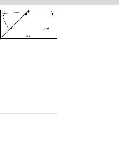
Winkelgenauigkeit zwischen 0°- und 45°-Laserlinie überprüfen
–Stellen Sie das Messwerkzeug in eine der Ecken der Messfläche. Schalten Sie das Messwerkzeug ein und richten Sie es so aus, dass die 0°-Laserlinie entlang der langen Seite der Messfläche und die 90°-Laserlinie entlang der kurzen Seite der Messfläche verläuft.
| <![if ! IE]> <![endif]>5 m |
10 m |
–Markieren Sie den Kreuzungspunkt der Laserlinien auf dem Boden (Punkt I). Markieren Sie außerdem die Mitte der 0°-Laserlinie in 5 m Entfernung (Punkt II) und in 10 m Entfernung (Punkt III).
–Stellen Sie das Messwerkzeug (ohne es zu drehen) in 5 m Entfernung so auf, dass der Kreuzungspunkt der Laserlinien den bereits markierten Punkt II trifft und die 0°-Laserlinie durch Punkt III verläuft. Markieren Sie die 45°-Laserlinie in 5 m Entfernung (Punkt IV).
Deutsch | 13
–Drehen Sie das Messwerkzeug so um 45°, dass die Mitte der 0°-Laserlinie durch Punkt IV verläuft.
Der Kreuzungspunkt der Laserlinien muss weiterhin auf Punkt II liegen.
Markieren Sie die 45°-Laserlinie in 5 m Entfernung als Punkt V.
–Drehen Sie das Messwerkzeug so um 45°, dass die Mitte der 0°-Laserlinie durch Punkt V verläuft.
Der Kreuzungspunkt der Laserlinien muss weiterhin auf Punkt II liegen.
Markieren Sie die 45°-Laserlinie in 5 m Entfernung als Punkt VI.
Bosch Power Tools |
1 609 929 S09 | (15.10.08) |
14 | Deutsch
<![if ! IE]><![endif]> d
d
–Drehen Sie das Messwerkzeug so um 45°, dass die Mitte der 0°-Laserlinie durch Punkt VI verläuft.
Der Kreuzungspunkt der Laserlinien muss weiterhin auf Punkt II liegen.
–Markieren Sie die Mitte der 45°-Laserlinie in 5 m Entfernung als Punkt VII möglichst nahe neben Punkt I.
–Die Differenz d der beiden Punkte VII und I ergibt die tatsächliche Abweichung der 0°-Laserlinie und der 45°-Laserlinie.
Auf der Messstrecke von 4 x 5 m = 20 m beträgt die maximal zulässige Abweichung: 20 m x ±0,4 mm/m* = ±8 mm.
Die Differenz d zwischen den Punkten I und VII darf folglich höchstens 8 mm betragen. * Der Wert ±0,4 mm/m ergibt sich aus der Winkelgenauigkeit ±0,2 mm/m zuzüglich einer möglichen Unsicherheit beim Drehen von 0,2 mm/m.
Arbeitshinweise
f Stellen Sie das Messwerkzeug immer plan auf den Boden bzw. befestigen Sie es plan an der Wand. Der Winkel ist bei unebener Aufstellung bzw. Befestigung kleiner als 45° bzw. 90°.
f Verwenden Sie immer nur die Mitte der Laserlinie zum Markieren. Die Breite der Laserlinie ändert sich mit der Entfernung.
fVerwenden Sie niemals die Laserlinien, die das am Boden stehende Messwerkzeug an die Wand wirft, zum Ausrichten.
Das Messwerkzeug ist nicht selbstnivellierend, die Linie an der Wand ist daher verzerrt.
fDer Referenzpunkt für das Ausrichten von Fliesen ist der Schnittpunkt P der Laserlinien direkt vor dem Messwerkzeug. Um einen Winkel zu übertragen, muss das Messwerkzeug an diesem Schnittpunkt gedreht werden, siehe Bild F.
fSetzen Sie das Messwerkzeug nur auf eine saubere Ausrichtplatte 10. Eine unebene, verschmutzte Oberfläche der Ausrichtplatte lässt das Messwerkzeug nicht plan stehen und kann die Messergebnisse verfälschen.
Arbeiten mit der Ausrichtplatte (siehe Bilder D–E)
Mit Hilfe der Ausrichtplatte 10 können Sie das Messwerkzeug auch auf unebenem oder lockerem Boden plan aufstellen.
Die Ausrichtplatte 10 ist ebenso als Wandhalterung für das Messwerkzeug geeignet. Befestigen Sie die Ausrichtplatte sicher gegen Verrutschen an einer Wand oder einer schrägen Fläche, z.B. mit Schrauben (handelsüblich). Verwenden Sie eine Wasserwaage, um die Ausrichtplatte plan auf der Fläche anzubringen.
Positionieren des Messwerkzeugs auf der Ausrichtplatte: Setzen Sie das Messwerkzeug mit den Magneten 4 an der Unterseite auf die Ausrichtplatte 10. Das Liniennetz auf der Oberseite der Ausrichtplatte hilft bei der genauen Positionierung des Messwerkzeugs.
1 609 929 S09 | (15.10.08) |
Bosch Power Tools |

Für die Übertragung von 90°- bzw. 45°-Win- keln legen Sie die Ausrichtplatte an eine Bezugskante oder an einen Mauervorsprung an und setzen das Messwerkzeug so auf, wie auf der Oberseite der Ausrichtplatte dargestellt.
Arbeiten mit der Laser-Zieltafel/Decken- messplatte (siehe Bild A)
Die Laser-Zieltafel 9 oder Deckenmessplatte 14 verbessert die Sichtbarkeit des Laserstrahls bei ungünstigen Bedingungen und größeren Entfernungen.
Die reflektierende Hälfte der Laser-Zieltafel 9 verbessert die Sichtbarkeit der Laserlinie, durch die transparente Hälfte ist die Laserlinie auch von der Rückseite der Laser-Ziel- tafel erkennbar.
Die Deckenmessplatte 14 (Zubehör) kann ebenfalls zum Anzeigen der Laserlinien eingesetzt werden. Wie die Laser-Zieltafel verfügt sie über eine reflektierende und eine transparente Hälfte.
Laser-Sichtbrille (Zubehör)
Die Laser-Sichtbrille filtert das Umgebungslicht aus. Dadurch erscheint das rote Licht des Lasers für das Auge heller.
fVerwenden Sie die Laser-Sichtbrille nicht als Schutzbrille. Die Laser-Sicht- brille dient zum besseren Erkennen des Laserstrahls, sie schützt jedoch nicht vor der Laserstrahlung.
fVerwenden Sie die Laser-Sichtbrille nicht als Sonnenbrille oder im Straßenverkehr. Die Laser-Sichtbrille bietet keinen vollständigen UV-Schutz und vermindert die Farbwahrnehmung.
Deutsch | 15
Arbeitsbeispiele
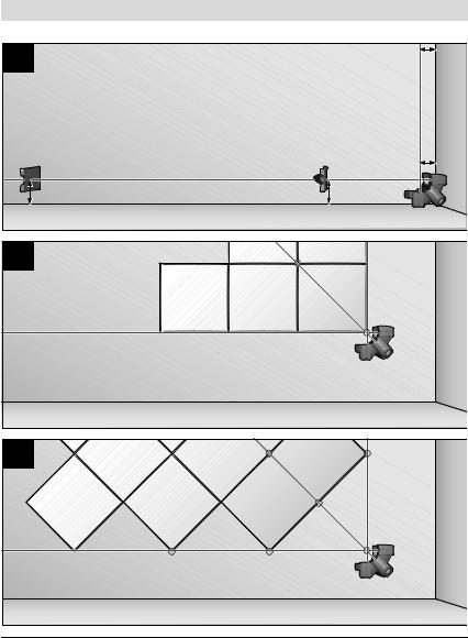
Überprüfen von rechten Winkeln (siehe Bild A)
Stellen Sie das Messwerkzeug in einer Ecke des Raumes auf und positionieren Sie es so, dass die 0°-Laserlinie parallel zur Bezugslinie (z.B. Wand) verläuft. Messen Sie den Abstand zwischen Laserlinie und Bezugslinie direkt am Messwerkzeug und in möglichst großem Abstand vom Messwerkzeug. Richten Sie das Messwerkzeug so aus, dass beide Abstände gleich groß sind.
Messen Sie anschließend an mindestens zwei verschiedenen Punkten die Abstände zwischen der 90°-Laserlinie und der Wand. Wenn die Abstände an der 90°-Laserlinie gleich sind, stehen die Wände im rechten Winkel.
Verlegung mit quadratischem Fliesenmuster (siehe Bild B)
Stellen Sie das Messwerkzeug in eine Ecke, sodass die 0°-Laserlinie parallel zu einer Wand verläuft. Legen Sie die erste quadratische Fliese an den Schnittpunkt der 0°- und der 90°-Laserlinie an.
Verlegung im Diagonalmuster (siehe Bild C)
Stellen Sie das Messwerkzeug so auf, dass die 45°-Laserlinie die diagonale Fliesenfuge markiert.
Küchenzeile fliesen (siehe Bild D)
Ermitteln Sie zunächst die Höhe, in der die erste Fliesenreihe beginnen soll. Befestigen Sie das Messwerkzeug mit der Ausrichtplatte 10 senkrecht an der Wand, sodass die 90°- Laserlinie die untere Kante der ersten Fliesenreihe anzeigt.
Bosch Power Tools |
1 609 929 S09 | (15.10.08) |

16 | Deutsch
Ab Kante fliesen (siehe Bild E)
Stellen Sie das Messwerkzeug auf der Ausrichtplatte 10 an die Kante, und zwar so, dass eine seitliche Aussparung 11 der Ausrichtplatte direkt an der Kante anliegt. Die 0°-Laserlinie sollte parallel zu einer Kante verlaufen. Die 90°-Laserlinie markiert nun die untere Fliesenreihe.
Wartung und Service
Wartung und Reinigung
Lagern und transportieren Sie das Messwerkzeug nur in der mitgelieferten Schutztasche.
Halten Sie das Messwerkzeug stets sauber.
Tauchen Sie das Messwerkzeug nicht ins Wasser oder andere Flüssigkeiten.
Wischen Sie Verschmutzungen mit einem feuchten, weichen Tuch ab. Verwenden Sie keine Reinigungsoder Lösemittel.
Reinigen Sie insbesondere die Flächen an der Austrittsöffnung des Lasers regelmäßig und achten Sie dabei auf Fusseln.
Sollte das Messwerkzeug trotz sorgfältiger Herstellungsund Prüfverfahren einmal ausfallen, ist die Reparatur von einer autorisierten Kundendienststelle für Bosch-Elektro- werkzeuge ausführen zu lassen.
Geben Sie bei allen Rückfragen und Ersatzteilbestellungen bitte unbedingt die 10-stelli- ge Sachnummer laut Typenschild des Messwerkzeugs an.
Senden Sie im Reparaturfall das Messwerkzeug in der Schutztasche 12 ein.
Kundendienst und Kundenberatung
Der Kundendienst beantwortet Ihre Fragen zu Reparatur und Wartung Ihres Produkts sowie zu Ersatzteilen. Explosionszeichnungen und Informationen zu Ersatzteilen finden Sie auch unter:
www.bosch-pt.com
Das Bosch-Kundenberater-Team hilft Ihnen gerne bei Fragen zu Kauf, Anwendung und Einstellung von Produkten und Zubehören.
www.powertool-portal.de, das Internetportal für Handwerker und Heimwerker. www.ewbc.de, der Informations-Pool für Handwerk und Ausbildung.
Deutschland
Robert Bosch GmbH Servicezentrum Elektrowerkzeuge Zur Luhne 2
37589 Kalefeld – Willershausen
Tel. Kundendienst: +49 (1805) 70 74 10 Fax: +49 (1805) 70 74 11
E-Mail: Servicezentrum.Elektrowerkzeuge@ de.bosch.com
Tel. Kundenberatung: +49 (1803) 33 57 99 Fax: +49 (711) 7 58 19 30
E-Mail: kundenberatung.ew@de.bosch.com
Österreich
ABE Service GmbH Jochen-Rindt-Straße 1 1232 Wien
Tel. Service: +43 (01) 61 03 80 Fax: +43 (01) 61 03 84 91
Tel. Kundenberater: +43 (01) 7 97 22 30 66 E-Mail: abe@abe-service.co.at
1 609 929 S09 | (15.10.08) |
Bosch Power Tools |

Schweiz
Tel.: +41 (044) 8 47 15 11
Fax: +41 (044) 8 47 15 51
Luxemburg
Tel.: +32 (070) 22 55 65
Fax: +32 (070) 22 55 75 E-Mail:
outillage.gereedschap@be.bosch.com
Entsorgung
Messwerkzeuge, Zubehör und Verpackungen sollen einer umweltgerechten Wiederverwertung zugeführt werden.
Nur für EU-Länder:
Werfen Sie Messwerkzeuge nicht in den Hausmüll!
Gemäß der Europäischen Richtlinie 2002/96/EG über
Elektround Elektronik-Alt- geräte und ihrer Umsetzung in
nationales Recht müssen nicht mehr gebrauchsfähige Messwerkzeuge getrennt gesammelt und einer umweltgerechten Wiederverwertung zugeführt werden.
Deutsch | 17
Akkus/Batterien:
Werfen Sie Akkus/Batterien nicht in den Hausmüll, ins Feuer oder ins Wasser. Akkus/ Batterien sollen gesammelt, recycelt oder auf umweltfreundliche Weise entsorgt werden.
Nur für EU-Länder:
Gemäß der Richtlinie 91/157/EWG müssen defekte oder verbrauchte Akkus/Batterien recycelt werden.
Nicht mehr gebrauchsfähige Akkus/Batterien können direkt abgegeben werden bei:
Deutschland
Recyclingzentrum Elektrowerkzeuge Osteroder Landstraße 3
37589 Kalefeld
Schweiz
Batrec AG
3752 Wimmis BE
Änderungen vorbehalten.
Bosch Power Tools |
1 609 929 S09 | (15.10.08) |
18 | English
Safety Notes
Working safely with the measuring tool is possible only when the operating and safety information are read completely and the instructions contained therein are strictly followed. Never make warning labels on the measuring tool unrecognisable. SAVE THESE INSTRUCTIONS.
fCaution – The use of other operating or adjusting equipment or the application of other processing methods than those mentioned here, can lead to dangerous radiation exposure.
fThe measuring tool is provided with a warning label in English (marked with number 2 in the representation of the measuring tool on the graphics page).
Do not direct the laser beam at persons or animals and do not stare into the laser beam yourself. This measuring tool produces laser class 2 laser radiation according to
IEC 60825-1. This can lead to persons being blinded.
fDo not use the laser viewing glasses as safety goggles. The laser viewing glasses are used for improved visualisation of the laser beam, but they do not protect against laser radiation.
fDo not use the laser viewing glasses as sun glasses or in traffic. The laser viewing glasses do not afford complete UV protection and reduce colour perception.
fHave the measuring tool repaired only through qualified specialists using original spare parts. This ensures that the safety of the measuring tool is maintained.
fDo not allow children to use the laser measuring tool without supervision.
They could unintentionally blind other persons or themselves.
1 609 929 S09 | (15.10.08) |
Bosch Power Tools |

Keep the measuring tool and the ceiling measurement plate 14 away from cardiac pace-
makers. The magnets 4 on the underside of the measuring tool as well as the magnets on
the ceiling measurement plate generate a field that can impair the function of cardiac pacemakers.
fKeep the measuring tool and the ceiling measurement plate 14 away from magnetic data medium and magneticallysensitive equipment. The effect of the magnets 4 on the underside of the measuring tool and the magnets on the ceiling measurement plate can lead to irreversible data loss.
Functional Description
Please unfold the fold-out page with the representation of the measuring tool and leave it unfolded while reading the operating instructions.
Intended Use
The measuring tool is intended for determining and checking right angles as well as for aligning tiles in angles of 45° and 90°.
English | 19
Product Features
The numbering of the product features shown refers to the illustration of the measuring tool on the graphic page.
1Exit opening for laser beam
2Laser warning label
3On/Off button
4Magnets
5Serial number
6Battery lid
7Latch of battery lid
8Battery indication
9Laser target plate
10Levelling plate
11Cut-out in the levelling plate
12Protective case
13Laser viewing glasses*
14Ceiling measurement plate*
*Accessories shown or described are not part of the standard delivery scope of the product.
A complete overview of accessories can be found in our accessories program.
Bosch Power Tools |
1 609 929 S09 | (15.10.08) |

20 | English
Technical Data
Tile laser |
GTL 3 |
|
Professional |
Article number |
3 601 K15 200 |
|
|
Working range (with laser target plate or with ceiling plate) |
20 m1) |
Angular accuracy |
± 0.2 mm/m2) |
Operating temperature |
– 10 °C ... +50 °C |
|
|
Storage temperature |
– 20 °C ... +70 °C |
|
|
Relative air humidity, max. |
90 % |
|
|
Laser class |
2 |
|
|
Laser type |
635 nm, <1 mW |
|
|
C6 |
1 |
Batteries |
4 x 1.5 V LR6 (AA) |
|
|
Operating life time |
|
– with 2 laser lines |
18 h |
– with 3 laser lines |
12 h |
|
|
Automatic switch-off after approx. |
30 min |
|
|
Weight according to EPTA-Procedure 01/2003 |
0.5 kg |
|
|
Dimensions |
156 x 102 x 98 mm |
|
|
Degree of protection |
IP 54 (dust and |
|
splash water protected) |
1)The working range can be decreased by unfavourable environmental conditions (e.g. direct sun irradiation).
2)The angular accuracy between the 45° laser line and the 90° laser line is max. ±0.4 mm/m.
Please observe the article number on the type plate of your measuring tool. The trade names of the individual measuring tools may vary.
The measuring tool can be clearly identified with the serial number 5 on the type plate.
1 609 929 S09 | (15.10.08) |
Bosch Power Tools |
Assembly
Inserting/Replacing the Battery
Alkali-manganese batteries are recommended for the measuring tool.
To open the battery lid 6, press on the latch 7 and fold the battery lid up. Insert the batteries. When inserting, pay attention to the correct polarity according to the representation on the inside of the battery compartment.
When the battery indication 8 flashes, the batteries are weak. When the battery indication flashes for the first time, the measuring tool can still be operated for approx. 2 h.
When the battery indication 8 lights up constantly, measuring is no longer possible. The measuring tool automatically switches off after a short time.
Always replace all batteries at the same time. Only use batteries from one brand and with the identical capacity.
fRemove the batteries from the measuring tool when not using it for extended periods. When storing for extended periods, the batteries can corrode and discharge themselves.
Operation
Initial Operation
fProtect the measuring tool against moisture and direct sun irradiation.
fDo not subject the measuring tool to extreme temperatures or variations in temperature. As an example, do not
English | 21
leave it in vehicles for longer periods. In case of large variations in temperature, allow the measuring tool to adjust to the ambient temperature before putting it into operation. In case of extreme temperatures or variations in temperature, the accuracy of the measuring tool can be impaired.
fAvoid heavy impacts or falling down of the measuring tool. If the measuring tool has been exposed to extreme conditions, you should always check the accuracy of the measuring tool before continuing your work (see “Angular accuracy”, page 22).
Switching On and Off
To switch on the measuring tool, press the On/Off button 3 once briefly. Immediately after the switching on, the measuring tool projects the three laser lines 0°, 45° and 90° from the exit openings 1. Furthermore, the battery indication 8 lights up for 3 s.
fDo not point the laser beam at persons or animals and do not look into the laser beam yourself, not even from a large distance.
When the On/Off button 3 is pressed a second time, the measuring tool switches over from 3-line operation to 2-line operation:
Only the 0° and the 90° laser lines are projected.
To switch off the measuring tool, press the On/Off button 3 a third time.
Bosch Power Tools |
1 609 929 S09 | (15.10.08) |

22 | English
Deactivating the Automatic Shut-off
The measuring tool switches off automatically after an operating duration of 30 minutes.
To deactivate the automatic switch-off, press the On/Off button 3 for 3 s when you switch on the measuring tool. When the automatic switch-off is deactivated, the laser lines flash briefly to confirm after the switching on.
fDo not leave the switched on measuring tool unattended and switch the measuring tool off after use. Other persons could be blinded by the laser beam.
To activate the automatic switch-off, switch the measuring tool off and switch it on again by pressing briefly the On/Off button 3. After the switching on, the laser lines do not flash.
Angular accuracy
Influences on Accuracy
The ambient temperature has the greatest influence. Especially temperature differences occurring from the ground upward can divert the laser beam.
Therefore, position the measuring tool as near as possible to the work surface and fix it with the underside as parallel as possible to the work surface.
Apart from exterior influences, device-spe- cific influences (such as heavy impact or falling down) can lead to deviations. Therefore, check the accuracy of the measuring tool each time before starting your work.
Checking the angular accuracy
For this check, you need a free surface of approx. 10 x 5 m on a stable and even base.
Should the measuring tool exceed the maximum deviation during one of the tests, please have it repaired by a Bosch after-sales service.
Checking the angular accuracy between the 0° and the 90° laser lines
–Position the measuring tool in one of the corners of the measuring surface. Switch on the measuring tool and align it so that the 0° laser line runs along the long side of the measuring surface and that the 90° laser line runs along the short side of the measuring surface.
| <![if ! IE]> <![endif]>5 m |
10 m |
–Mark the crossing point of the laser lines on the floor (Point I). Mark also the centre of the 0° laser line at a distance of 5 m (Point II) and at a distance of 10 m (Point III).
1 609 929 S09 | (15.10.08) |
Bosch Power Tools |

–Position the measuring tool (without turning it) at a distance of 5 m so that the crossing point of the laser lines is on the already marked point II and that the 0° laser line runs through the point III. Mark the centre of the 90° laser line at a distance of 5 m (Point IV).
<![if ! IE]><![endif]> d
d
– Turn the measuring tool by 90° so that the centre of the 0° laser line runs through the point IV.
The crossing point of the laser lines must still be on the point II.
– Mark the centre of the 90° laser line at a distance of 5 m as point V as near as possible next to the point I.
– The difference d of the two points V and I is the actual deviation of the 0° laser line and the 90° laser line from the right angle.
English | 23
The measuring length 2 x 5 m = 10 m has a maximum admissible deviation of:
10 m x ±0.2 mm/m = ±2 mm. Therefore, the maximum difference d be-
tween the points I and V may be 2 mm or less.
Checking the angular accuracy between the 0° and the 45° laser lines
–Position the measuring tool in one of the corners of the measuring surface. Switch on the measuring tool and align it so that the 0° laser line runs along the long side of the measuring surface and that the 90° laser line runs along the short side of the measuring surface.
| <![if ! IE]> <![endif]>5 m |
10 m |
–Mark the crossing point of the laser lines on the floor (Point I). Mark also the centre of the 0° laser line at a distance of 5 m (Point II) and at a distance of 10 m (Point III).
Bosch Power Tools |
1 609 929 S09 | (15.10.08) |

24 | English
–Position the measuring tool (without turning it) at a distance of 5 m so that the crossing point of the laser lines is on the already marked point II and that the 0° laser line runs through the point III. Mark the 45° laser line at a distance of
5 m (Point IV).
–Turn the measuring tool by 45° so that the centre of the 0° laser line runs through the point IV.
The crossing point of the laser lines must still be on the point II.
Mark the 45° laser line at a distance of 5 m as point V.
–Turn the measuring tool by 45° so that the centre of the 0° laser line runs through the point V.
The crossing point of the laser lines must still be on the point II.
Mark the 45° laser line at a distance of 5 m as point VI.
<![if ! IE]><![endif]> d
d
– Turn the measuring tool by 45° so that the centre of the 0° laser line runs through the point VI.
The crossing point of the laser lines must still be on the point II.
– Mark the centre of the 45° laser line at a distance of 5 m as point VII as near as possible next to the point I.
– The difference d of the two points VII and I is the actual deviation of the 0° laser line and the 45° laser line.
1 609 929 S09 | (15.10.08) |
Bosch Power Tools |

The measuring length 4 x 5 m = 20 m has a maximum admissible deviation of:
20 m x ±0.4 mm/m* = ±8 mm.
Therefore, the maximum difference d between the points I and VII may be 8 mm or less.
* The value ±0.4 mm/m results from the angle accuracy ±0.2 mm/m plus a possible uncertainty of 0.2 mm/m while turning.
Working Advice
fAlways position the measuring tool flat on the floor or fix it flat on the wall. In case of uneven positioning or fixing, the angle is smaller than 45° and 90°.
fAlways use the centre of the laser line for marking. The width of the laser line changes with the distance.
fNever use the laser lines that the measuring tool standing on the floor projects on the wall for alignment. The measuring tool is not self-levelling. Therefore, the line on the wall is distorted.
fThe reference point for the alignment of tiles is the crossing point P of the laser lines directly in front of the measuring tool. In order to mark an angle, the measuring tool has to be turned at this crossing point, see figure F.
fPosition the measuring tool only on a clean levelling plate 10. The measuring tool cannot stand level on an uneven, soiled levelling plate surface, which could lead to faulty measuring results.
English | 25
Working with the levelling plate (see figures D–E)
Using the levelling plate 10 you can position the measuring tool flat on an uneven or unstable floor.
The levelling plate 10 can also be used as a wall bracket for the measuring tool. Fix the levelling plate (securing it against slipping) on a wall or an inclined surface using e.g. standard screws. Use a level to fix the levelling plate flat on the surface.
Positioning of the measuring tool on the levelling plate: Position the measuring tool with the magnets 4 on the underside on the levelling plate 10. The line grid on the upper side of the levelling plate facilitates the precise positioning of the measuring tool. In order to mark 90° or 45° angles, position the levelling plate at a reference edge or a projection on a wall and position the measuring tool as illustrated on the upper side of the levelling plate.
Working with the laser target plate/ceiling measurement plate (see figure A)
The laser target plate 9 or the ceiling measurement plate 14 improves the visibility of the laser beam under unfavourable conditions and at longer distances.
The reflective part of the laser target plate 9 improves the visibility of the laser line. Thanks to the transparent part, the laser line is also visible from the back side of the laser target plate.
The ceiling measurement plate 14 (accessory) can also be used for marking the laser lines. Like the laser target plate, it has a reflective and a transparent part.
Bosch Power Tools |
1 609 929 S09 | (15.10.08) |

26 | English
Laser Viewing Glasses (Accessory)
The laser viewing glasses filter out the ambient light. This makes the red light of the laser appear brighter for the eyes.
fDo not use the laser viewing glasses as safety goggles. The laser viewing glasses are used for improved visualisation of the laser beam, but they do not protect against laser radiation.
fDo not use the laser viewing glasses as sun glasses or in traffic. The laser viewing glasses do not afford complete UV protection and reduce colour perception.
Work Examples
Checking right angles (see figure A)
Position the measuring tool in one corner of the room and position it so that the 0° laser line runs parallel to the reference line (e.g. wall). Measure the distance between the laser line and the reference line directly at the measuring tool and at the longest possible distance from the measuring tool. Align the measuring tool so that both distances are identical.
Then measure at at least two different points the distances between the 90° laser line and the wall. If the distances to the 90° laser line are identical, the walls are at the right angle.
Laying of square tiles (see figure B)
Position the measuring tool in one corner so that the 0° laser line runs parallel to one wall. Lay the first square tile at the crossing point of the 0° and the 90° laser lines.
Laying with diagonal pattern (see figure C)
Position the measuring tool so that the 45° laser line marks the diagonal tile joint.
Tile laying in kitchenettes (see figure D)
Firstly determine the height at which the first tile row begins. Fix the measuring tool with the levelling plate 10 vertically on the wall so that the 90° laser line marks the lower edge of the first tile row.
Laying from edges (see figure E)
Position the measuring tool on the levelling plate 10 at the edge so that a lateral cut-out 11 of the levelling plate is directly at the edge. The 0° laser line should run parallel to one edge. The 90° laser line now marks the lower tile row.
1 609 929 S09 | (15.10.08) |
Bosch Power Tools |

Maintenance and Service
Maintenance and Cleaning
Store and transport the measuring tool only in the supplied protective case.
Keep the measuring tool clean at all times.
Do not immerse the measuring tool into water or other fluids.
Wipe off debris using a moist and soft cloth. Do not use any cleaning agents or solvents.
Regularly clean the surfaces at the exit opening of the laser in particular, and pay attention to any fluff of fibres.
If the measuring tool should fail despite the care taken in manufacturing and testing procedures, repair should be carried out by an authorized after-sales service centre for Bosch power tools.
In all correspondence and spare parts orders, please always include the 10-digit article number given on the type plate of the measuring tool.
In case of repairs, send in the measuring tool packed in its protective case 12.
English | 27
After-sales Service and Customer Assistance
Our after-sales service responds to your questions concerning maintenance and repair of your product as well as spare parts. Exploded views and information on spare parts can also be found under: www.bosch-pt.com
Our customer consultants answer your questions concerning best buy, application and adjustment of products and accessories.
Great Britain
Robert Bosch Ltd. (B.S.C.)
P.O. Box 98
Broadwater Park
North Orbital Road
Denham
Uxbridge
UB 9 5HJ
Tel. Service: +44 (0844) 736 0109
Fax: +44 (0844) 736 0146
E-Mail: SPT-Technical.de@de.bosch.com
Ireland
Origo Ltd.
Unit 23 Magna Drive
Magna Business Park
City West
Dublin 24
Tel. Service: +353 (01) 4 66 67 00
Fax: +353 (01) 4 66 68 88
Bosch Power Tools |
1 609 929 S09 | (15.10.08) |

28 | English
Australia, New Zealand and Pacific Islands
Robert Bosch Australia Pty. Ltd. Power Tools
Locked Bag 66
Clayton South VIC 3169
Customer Contact Center Inside Australia:
Phone: +61 (01300) 307 044 Fax: +61 (01300) 307 045 Inside New Zealand:
Phone: +64 (0800) 543 353 Fax: +64 (0800) 428 570 Outside AU and NZ: Phone: +61 (03) 9541 5555 www.bosch.com.au
People’s Republic of China
Website: www.bosch-pt.com.cn
China Mainland
Bosch Power Tools (China) Co., Ltd. 567, Bin Kang Road
Bin Jiang District 310052 Hangzhou, P.R.China
Service Hotline: 800 8 20 84 84 Tel.: +86 (571) 87 77 43 38 Fax: +86 (571) 87 77 45 02
HK and Macau Special Administrative Regions
Robert Bosch Hong Kong Co. Ltd. 21st Floor, 625 King’s Road North Point, Hong Kong Customer Service Hotline:
+852 (21) 02 02 35 Fax: +852 (25) 90 97 62
E-Mail: info@hk.bosch.com www.bosch-pt.com.cn
Indonesia
PT. Multi Tehaka
Kawasan Industri Pulogadung Jalan Rawa Gelam III No. 2 Jakarta 13930
Indonesia
Tel.: +62 (21) 4 60 12 28 Fax: +62 (21) 46 82 68 23
E-Mail: sales@multitehaka.co.id www.multitehaka.co.id
Philippines
Robert Bosch, Inc. Zuellig Building
Sen. Gil Puyat Avenue
Makati City 1200, Metro Manila Philippines
Tel.: +63 (2) 8 17 32 31 www.bosch.com.ph
1 609 929 S09 | (15.10.08) |
Bosch Power Tools |

English | 29
Malaysia |
Singapore |
|
Robert Bosch (SEA.) Pte. Ltd. |
Robert Bosch (SEA.) Pte. Ltd. |
|
No. 8a, Jalan 13/6 |
38 C Jalan Pemimpin |
|
46200 Petaling Jaya, |
Singapore 915701 |
|
Selangor, |
Republic of Singapore |
|
Malaysia |
Tel.: +65 (3) 50 54 94 |
|
Tel.: +6 (03) 7966 3000 |
Fax: +65 (3) 50 53 27 |
|
Fax: +6 (03) 7958 3838 |
www.bosch.com.sg |
|
E-Mail: hengsiang.yu@my.bosch.com |
Vietnam |
|
Toll Free Tel.: 1 800 880 188 |
||
|
||
Fax: +6 (03) 7958 3838 |
Robert Bosch (SEA) Pte. Ltd – Vietnam |
|
www.bosch.com.sg |
Representative Office |
|
Thailand |
Saigon Trade Center, Suite 1206 |
|
37 Ton Duc Thang Street, |
||
|
||
Robert Bosch Ltd. |
Ben Nghe Ward, District 1 |
|
Liberty Square Building |
HCMC |
|
No. 287, 11 Floor |
Vietnam |
|
Silom Road, Bangrak |
Tel.: +84 (8) 9111 374 – 9111 375 |
|
Bangkok 10500 |
Fax: +84 (8) 9111376 |
|
Tel.: +66 (2) 6 31 18 79 – 18 88 (10 lines) |
|
|
Fax: +66 (2) 2 38 47 83 |
|
|
Robert Bosch Ltd., P. O. Box 2054 |
|
|
Bangkok 10501, Thailand |
|
|
Bosch Service – Training Centre |
|
|
2869-2869/1 Soi Ban Kluay |
|
|
Rama IV Road (near old Paknam Railway) |
|
|
Prakanong District |
|
|
10110 Bangkok |
|
|
Thailand |
|
|
Tel.: +66 (2) 6 71 78 00 – 4 |
|
|
Fax: +66 (2) 2 49 42 96 |
|
|
Fax: +66 (2) 2 49 52 99 |
|
Bosch Power Tools |
1 609 929 S09 | (15.10.08) |

30 | English
Disposal
Measuring tools, accessories and packaging should be sorted for environmental-friendly recycling.
Only for EC countries:
Do not dispose of measuring tools into household waste!
According the European Guideline 2002/96/EC for
Waste Electrical and Electronic Equipment and its implemen-
tation into national right, measuring tools that are no longer usable must be collected separately and disposed of in an environmentally correct manner.
Battery packs/batteries:
Do not dispose of battery packs/batteries into household waste, fire or water. Battery packs/batteries should be collected, recycled or disposed of in an environmentalfriendly manner.
Only for EC countries:
Defective or dead out battery packs/batteries must be recycled according the guideline 91/157/EEC.
Batteries no longer suitable for use can be directly returned at:
Great Britain
Robert Bosch Ltd. (B.S.C.)
P.O. Box 98
Broadwater Park
North Orbital Road
Denham
Uxbridge
UB 9 5HJ
Tel. Service: +44 (0844) 736 0109
Fax: +44 (0844) 736 0146
E-Mail: SPT-Technical.de@de.bosch.com
Subject to change without notice.
1 609 929 S09 | (15.10.08) |
Bosch Power Tools |
 Loading...