

Page 1

Repair Manual
R 1100 S
BMW AG Motorcycle Division
After Sales
Page 2

Published by: © BMW AG Motorcycle Division
After Sales
UX-VS-2
All rights reserved. Not to be reprinted, translated or duplicated either wholly or in part without prior written
permission.
Errors and omissions excepted; subject to technical amendment.
Produced in Germany 06/99
Page 3
Introduction
This repair manual will help you to perform all the main maintenance and repair work correctly and efficiently. It should be consulted regularly by workshop personnel as an addition to the practical and theoretical
knowledge obtained in Training School courses. It is a contribution towards achieving even higher Service
quality.
All information in both text and illustrations refers to motorcycles in standard condition or with genuine
BMW accessories installed, and not to motorcycles which have been modified in any way to depart from
the manufacturer’s specification.
● The repair manual is structured in the logical sequence of the work to be performed: Removal, Dis-
assembly, Repair, Assembly, Installation.
● The entire contents are divided into individual chapters, corresponding to the Construction Groups.
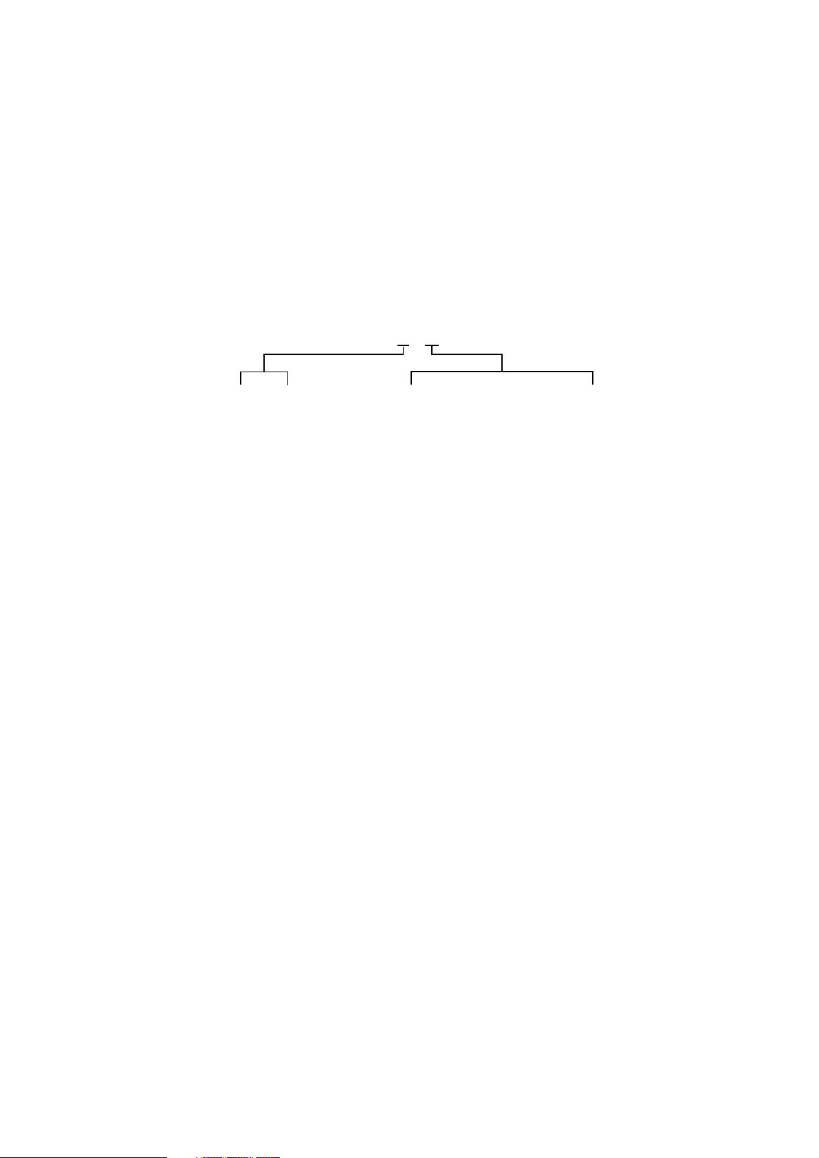
11 . 10
Chap. Page number within chapter
● Work to be performed during an Inspection is described in Group “00”. The various inspection routines
are numbered I, II, III and IV. This numbering is repeated in the work descriptions which follow, so that
work can take place without interruption.
● Use of the BMW special tools needed for certain tasks is described in the work instructions.
If the need arises, repair instructions are also issued in the form of Service Information. This information is
of course incorporated into the next issue of the repair manual. We also recommend you to consult the
detailed illustrations on the Parts microfiches as an additional source of information.
BMW AG Motorcycle Division
After Sales
Published by: BMW AG, Sparte Motorrad
Hufelandstr. 6
D - 80937 München
All rights reserved. Not to be reprinted, translated or duplicated either wholly or in part without prior written
permission.
Errors and omissions excepted; subject to technical amendment.
Produced in Germany
Page 4

Page 5
Contents
Group / Chapter
00 Maintenance and general instructions
11 Engine
12 Engine electrics
13 Fuel preparation and control
16 Fuel tank and lines
18 Exhaust system
21 Clutch
23 Gearbox
31 Front fork
32 Steering
33 Rear wheel drive
3
Page 6
Group / Chapter
34 Brakes
36 Wheels and tyres
46 Frame
51 Equipment
52 Seat
61 General electrical equipment
62 Instruments
63 Lights
5
Page 7
BMW AG Motorcycle Division
Maintenance schedule
R 1100 S
Customer Licence plate No.
Order No. Mechanic’s signature
Read out the fault memory with the BMW MoDiTeC unit
Change the oil while at regular operating temperature and renew the oil filter
element
if motorcycle is used only for short journeys or at outside temperatures under 0°C, every 3 months,
but at least every 3,000 km (1,800 miles)
)
*
BMW Inspection
at 1,000 km
(600 miles)
BMW Service
every 10,000 km
(6,000 miles)
BMW Inspection
every 20,000 km
(12,000 miles)
BMW
Annual Service
Change the oil in the gearbox while at regular operating temperature
at least every 2 years
every
2 years
Change the oil in the rear wheel drive while at regular operating temperature
Clean the inductive sensor at the rear wheel
every 40,000 km (24,000 miles) or at least every 2 years *
Renew fuel filter *
normally every 40,000 km (24,000 miles), if fuel quality is poor every 20,000 km (12,000 miles)
)
)
40,000
(24,000)
40,000
(24,000)
every
2 years
Check battery acid level, if necessary add distilled water
Clean/grease battery poles if necessary
Renewing intake air cleaner element
in very dusty or dirty operating conditions, renew the intake air cleaner element
every 10,000 km (6,000 miles) or even more often if necessary
Renew Poly-V belt *
Renew Poly-V belt every 60,000 km (36,000 miles); do not adjust
)
Check brake fluid level at front/rear and top up if necessary *
Check operation of brake system and freedom from leaks;
repair/renew items if necessary *
)
Examine brake pads and discs for wear, renew if necessary *
)
*
60,000
(36,000)
)
)
Renew the brake fluid annually
Check clutch operating fluid level
Change clutch fluid
every 40,000 km (24,000 miles) or at least every 2 years *
)
40,000
(24,000)
every
2 years
Check tightness of rear wheel studs
Check rear wheel bearing play by tilting wheel
Check swinging arm bearings (zero play); adjust if necessary *
)
Grease the side (prop) stand pivot
Check function of side (prop) stand contact switch
Check condition of spark plugs
Renew spark plugs *
)
Take up slack at cylinder head nuts
Check/adjust valve operating clearances
Check throttle cable for free movement, abrasion and kinking; renew if necessary *
Check free travel in throttle cable
Check synchronisation and eliminate any leaks *
)
)
Final inspection with road safety and functional check:
– condition of tyres and wheels, tyre pressures
– lights and signalling equipment
– telltale and warning lights
– clutch, gear shift
– handbrake and foot brake, steering
– instruments
– trial run if necessary
)
*
Charged as an additional item
Order No. 01 71 7 654 263 UX-VS-2, 3.99 Printed in Germany
Page 8

BMW AG Motorcycle Division
Pre-delivery check
R 1100 S
Customer Licence plate No.
Order No. Mechanic’s signature
Checking the shipping crate for damage
Motorcycle:
– unpack
– attach items supplied loose
– inspect for damage
– check that delivery is complete: tools
documentation
keys
correct optional extras
Fill and charge the battery (mark with charging date)
Check engine oil level when cold; add oil if necessary
BMW
Pre-delivery check
Check clutch operating fluid level and brake fluid levels at front and rear
Check headlight beam angle and adjust if necessary
Checking tightness of rear wheel studs
(comply with correct tightening torque)
Check tyre pressures
Add fuel
Final inspection and functional check:
– clutch, gear shift
– handbrake, foot brake
– lighting and signalling equipment, telltale lights, instruments
– check operation of optional extras, ABS
– trial run if necessary
Confirm pre-delivery check in Service and Technical Booklet
Final cleaning
Motorcycle handed over on:
Order No. 01 71 7 654 263 UX-VS-2, 3.99 Printed in Germany
Page 9

00
00 Maintenance and general instructions
Tightening torques and Table of consumables
Pre-delivery check
Maintenance
Contents Page
Tightening torques ......................................................................................................................5
Table of consumables ..............................................................................................................11
00.1
Page 10

Pre-delivery check
Contents - Pre-delivery check Page
Pre-delivery check .....................................................................................................................13
General view of crated motorcycle ..................................................................................13
Checking the crate for damage ..........................................................................................14
In case of damage in Germany ...............................................................................................14
In case of damage in importer markets ..............................................................................14
Unpacking the motorcycle ....................................................................................................14
Installing remaining items on
motorcycle .....................................................................................................................................14
Inspecting motorcycle for damage ..................................................................................14
Checking that delivery is complete ..................................................................................14
Filling and charging the battery .........................................................................................15
Disengaging and raising the fuel tank .................................................................................15
Filling and charging the battery ..............................................................................................15
Checking engine oil level when cold, adding oil if necessary ...........................16
Checking clutch fluid level ....................................................................................................17
Checking brake fluid level .....................................................................................................17
Rear brake .......................................................................................................................................17
Front brake ......................................................................................................................................17
Checking headlight beam angle, adjusting if necessary .....................................18
Checking tightness of rear wheel studs ........................................................................18
Checking tyre pressures ........................................................................................................18
Final inspection and function check ...............................................................................19
Final cleaning ...............................................................................................................................19
Handing over the motorcycle ..............................................................................................19
00.2
Page 11

Maintenance
Contents - Maintenance Page
Maintenance .................................................................................................................................20
Key to maintenance intervals ..............................................................................................20
Reading out MoDiTeC fault memory ...............................................................................20
(Inspections I, II, III and IV)
Changing engine oil, replacing oil filter element ......................................................20
(Inspections I, II, III and IV)
Changing oil in gearbox ..........................................................................................................21
(Inspections III and IV)
or every 2 years at the latest
Changing oil in rear wheel drive; cleaning inductive signal transmitter at
rear wheel .......................................................................................................................................22
(Inspections I, III and IV)
Every 40 000 km (24 000 miles) or every 2 years at the latest
Replacing fuel filter ...................................................................................................................23
(Inspection III)
In normal operating conditions every 40 000 km (24 000 miles); if fuel quality is poor every
20 000 km (12 000 miles)
Checking battery fluid level and
topping up if necessary; cleaning and greasing the battery posts .................25
(Inspections III and IV)
Replacing intake air filter element ....................................................................................25
(Inspection III)
In very dirty and dusty operating conditions, replace every 10 000 km (6 000 miles) or even more frequently if necessary
Replacing Poly-V belt ...............................................................................................................26
(every 60 000 km/36 000 miles)
(Inspection III)
Poly-V belt adjusting procedure:
Checking brake fluid level .....................................................................................................27
Front brake ......................................................................................................................................27
Rear brake .......................................................................................................................................27
Checking brake pads and discs for wear/replacing ...............................................28
(Inspections II and III)
Checking front brake pad wear ..............................................................................................28
Checking rear brake pad wear ...............................................................................................28
Checking brake disc wear ........................................................................................................28
Replacing brake pads, front brake .......................................................................................29
Replacing brake pads, rear brake .........................................................................................29
00.3
Page 12

Contents - Maintenance Page
Changing brake fluid and bleeding brake system ...................................................30
Change the brake fluid annually
(Inspection IV)
[ABS Inspections II and III]
Bleeding front brake circuit/changing brake fluid ..........................................................30
Additional information for [ABS]
Bleeding rear brake circuit/changing brake fluid ............................................................32
Checking clutch fluid level ....................................................................................................33
(Inspections I, II and III)
Changing the clutch fluid .......................................................................................................33
(Inspections III and IV)
Every 40 000 km (24 000 miles) or every 2 years at the latest
Checking tightness of rear wheel studs ........................................................................34
(Inspection I)
Checking rear wheel bearing play by tilting wheel .................................................34
(Inspection III)
Checking swinging arm bearings, adjusting if necessary ...................................34
(Inspections I and III)
Greasing the side stand pivot ..............................................................................................35
(Inspections I, II and III)
Checking function of side stand switch ........................................................................35
(Inspections I, II, III and IV)
Checking/replacing spark plugs ........................................................................................35
(Inspection II) check/(Inspection III) replace
Tightening cylinder heads .....................................................................................................36
(Inspection I)
Checking/adjusting valve
clearances ......................................................................................................................................36
(Inspections I, II and III)
Checking throttle cable for ease of movement, abrasion and kinks; replacing if necessary
Checking throttle-cable play
Checking/adjusting idle speed and throttle-valve synchronisation ...............37
(Inspections I, II, III and IV)
Final inspection with road safety and functional check .......................................38
(Inspections I, II, III and IV)
Road safety check
Roadworthiness check
00.4
Page 13
00
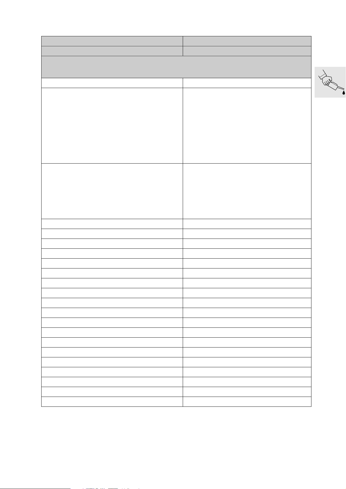
Tightening torques
Model R 1100 S
Connection Nm
11 Engine
Cylinder head
Tightening sequence:
1. Tighten cylinder head nuts (oiled) in diagonally
opposite sequence
1.1 Tighten all nuts to closing torque 20
1.2 Tighten all nuts to wrench angle 90°
1.3 Tighten all nuts to wrench angle 90°
2. M 10 screw 40
3. M 6 screw 9
After 1000 km (600 miles), tighten cylinder head nuts in
diagonally opposite sequence:
1. Slacken one nut
2. Tighten one nut to initial torque 20
3. Tighten nut to wrench angle 180°
4. Slacken and retighten M 10 screw 40
Timing gear carrier to cylinder head
Bearing cap on rocker shaft 15
Locknut, valve adjusting screw 8
Cylinder head cover to cylinder head 9
Camshaft end cover to cylinder head
Air intake connection to cylinder head
Camshaft
Chain sprocket to camshaft 65
Camshaft bearing cap 15
Alternator mount cover
M 6 screw 9
M 8 screw 20
Auxiliary shaft
Chain sprocket to crankshaft 10
Chainwheel to auxiliary shaft 70
Chain tensioner housing to engine block 9
9
9
9
Oil filter
Oil filter 11
Oil drain plug 32
00.5
Page 14
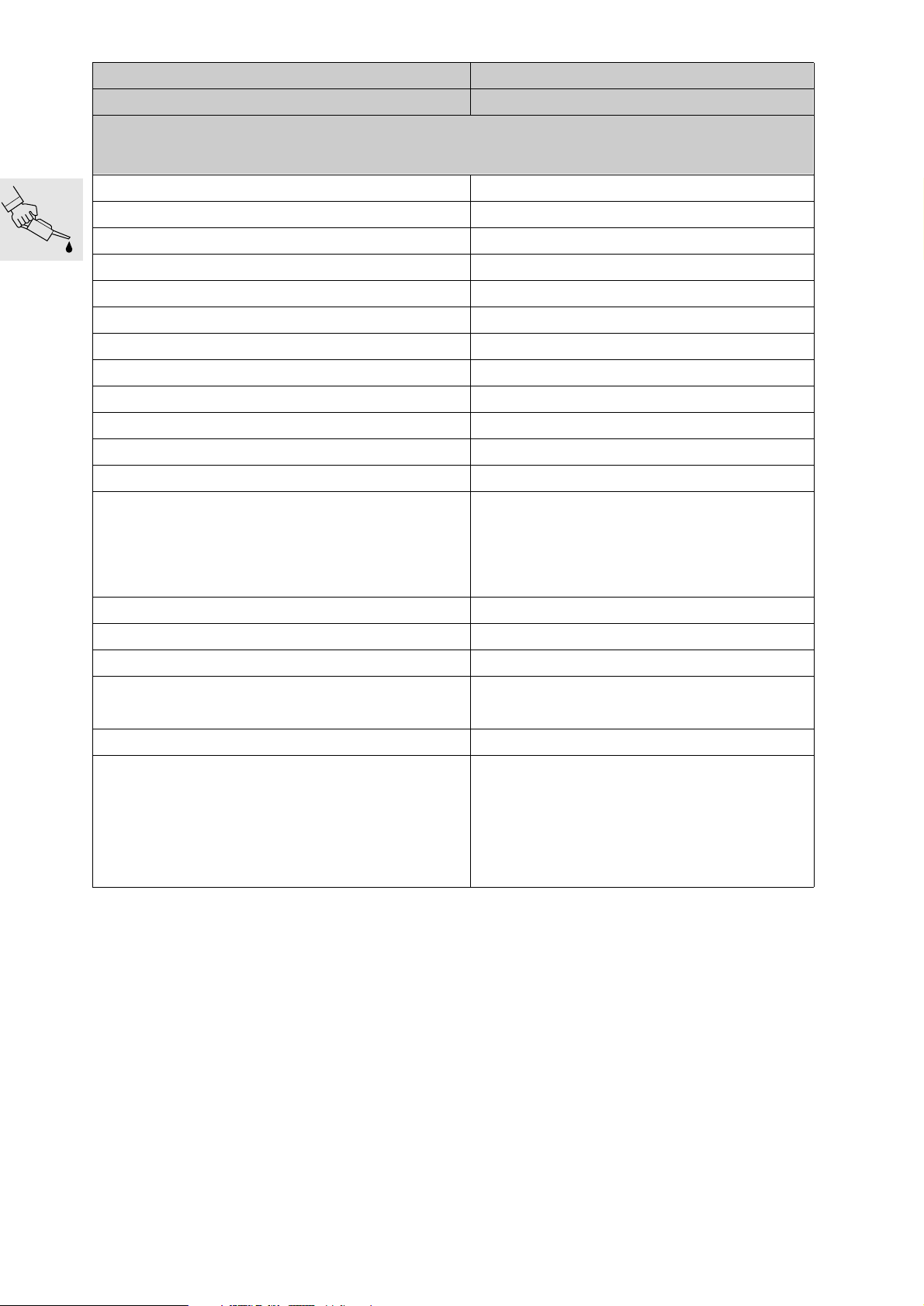
Model R 1100 S
Connection Nm
11 Engine
Oil pump
Mesh filter basket to engine block 9
Oil pump cover 9
Pressure relief valve 42
Oil pressure switch 30
Oil cooler
Oil cooler pipe to engine block 10
Cooling oil line – banjo screw with oil vent valve 25
Oil cooler to fairing bracket 9
Oil cooler return line to engine block 35
Oil cooler connection to crankcase 9
Cylinders
Tightening sequence:
1. M 8 screw 20
2. M 6 screw 9
3. Chain guide rail pivot screw 18
Timing chain
Chain tensioner 32
Connecting rod
Big end cap Closing torque 20
Wrench angle 80°
Crankcase
Tightening sequence:
1. M 10 screw (oiled) Initial torque 25
Wrench angle 90°
2. M 8 screw (oiled) 22
3. M 6 screw 9
00.6
Page 15
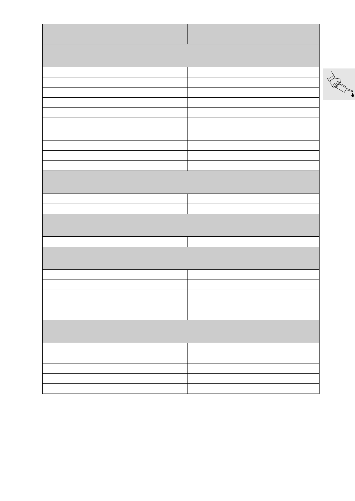
Model R 1100 S
Connection Nm
12 Engine electrics
Starter motor to engine 20
Starter cover to gearbox housing 7
Alternator to cover mount 20
Tensioning and retaining link to alternator 20
Spacer to alternator 20
Belt pulley to alternator
Series generator 560 W
Option 700 W
Belt pulley to crankshaft 50
Poly-V belt preload 8
Spark plug 20
13 Fuel preparation and control
Temperature sensor, oil, in crankcase 25
Do not release
50
Temperature sensor, air, in air-filter housing 10
16 Fuel tank and lines
Fuel tank to main frame 10
18 Exhaust system
Manifold to cylinder head 21
Clamp for manifold 45 (apply Never Seeze to clamp seat)
Manifold to front silencer 12
Silencer to front-silencer outlet 55 (apply Never Seeze to clamp seat)
Oxygen sensor to silencer 45 (apply Never Seeze to thread)
21 Clutch
Clutch housing Closing torque
Wrench angle 32°
Housing cover 12
Slave cylinder to gearbox 9
40 (oil screw threads lightly)
Clutch line to handlebar fitting 18
00.7
Page 16
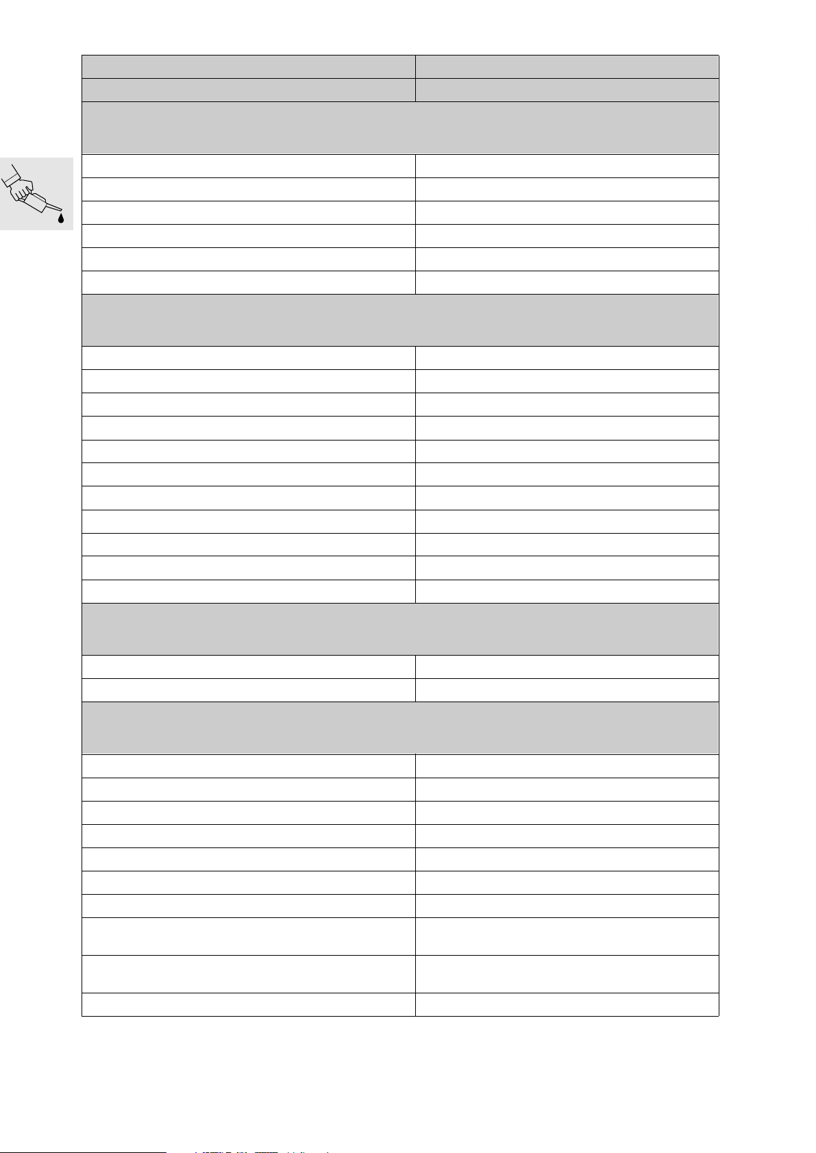
Model R 1100 S
Connection Nm
23 Transmission
Oil drain plug 55
Oil filler plug 23
Gearbox to engine block 22
Foot shift lever to footrest plate 21
Selector lever to selector shaft 9
Gearbox cover to gearbox housing 9
31 Front fork
Quick-release axle clamp screws 22
Clamp, fork fixed tube to fork bridge 22
Slider tube bridge to slider tube 25 (clean thread + Loctite 243)
Ball joint to fork bridge 230 (apply light coat of Never Seeze to thread)
Ball joint to tube slider bridge 230 (apply light coat of Never Seeze to thread)
Leading link tube to ball joint 130 (clean thread + Loctite 2701)
Frame to ball joint 130 (clean thread + Loctite 2701)
Leading link tube to engine right 73
Screw cap to leading link left 42 (apply light coat of Never Seeze to thread)
Suspension strut to front frame
Suspension strut to leading link 50
32 Steering
Handlebar to fixed tube 21
Handlebar to fork bridge 9 (clean thread + Loctite 243)
33 Rear wheel drive
Oil filler plug 23
Oil drain plug 23
Threaded ring 118 (Hylomar SQ 32 M)
Hexagon nut, input bevel gear
Cover to rear-wheel drive housing 35
43
200 (clean thread + Loctite 2701)
Swinging-arm fixed bearing stud bolt to rear frame 9
Swinging-arm floating bearing stud bolt to rear frame 7 (clean thread + Loctite 2701)
Swinging-arm floating bearing stud bolt to rear axle
housing 160 (clean thread + Loctite 2701)
Swinging-arm floating bearing stud bolt to rear-axle
housing 7 (clean thread + Loctite 2701)
Locknut of swinging-arm floating bearing stud bolt 160
00.8
Page 17
Model R 1100 S
Connection Nm
33 Rear wheel drive
Reaction link to rear wheel drive/main frame 43
Load approx. 85 kg (187 lbs) onto motorcycle and
tighten loose reaction link
Spring strut to main frame 50
Spring strut to rear swinging arm 50
34 Brakes
Brake caliper to fork slider tube 40
Brake caliper to rear wheel drive 40
Brake disc to front wheel 21 (clean thread + Loctite 2701)
Brake disc to rear wheel drive 21 (clean thread + Loctite 2701)
Master cylinder to footrest assembly 8
Brake pedal to footrest assembly
Brake lines/brake hose to brake components 18
Brake hose to brake lever fitting 18
ABS sensor 4 (handtight)
Front brake caliper bleed screw
Rear brake caliper bleed screw 6
Pressure modulator bleed screw
Grubscrew in filler adapter
ABS unit to holder
M6 screw 9
36 Wheels and tyres
Quick-release axle clamp screws 22
Quick-release axle threaded connection 30
Rear wheel to rear wheel drive
Hand-tighten wheel studs, then tighten in diagonally
opposite sequence
Initial tightening 50
21 (clean thread + Loctite 2701)
14
9
10
Final tightening 105
46 Frame
Front frame to engine, M12 bolts 82
Struts to front frame 58
00.9
Page 18
Model R 1100 S
Connection Nm
46 Frame
Main frame to engine
M 10 screw, top right Initial tightening 13
Final tightening 42
M 10 screw, top left 42
M 10 bolts at top (struts to engine) 50
M 10 screw, long, frame/gearbox 55
M 12 screw, bottom 80
M 8 screw, long, bottom 24
Rear frame to main frame 31
Side stand pivot mount to engine
M 8 screw 21
M 12 screw 80
Side stand to pivot mount 42 (clean thread + Loctite 243)
Centre stand to main frame 42
Footrest assembly to main frame 21
Pillion footrest holder to rear frame 21
Front fairing bracket to front frame 21
51 Equipment
Mirrors 10 (clean thread + Loctite 243)
Ignition/steering lock to fork bridge 15 (microencapsulated)
61 General electrical equipment
Horn to holder 21
Ground (earth) strap to engine block 7
00.10
Page 19

Table of consumables
Item Use Order number Quantity
Lubricant
Optimoly MP 3 High-performance lubricating paste 07 55 9 062 476 100 g tube
Optimoly TA High-temperature assembly paste 18 21 9 062 599 100 g tube
Silicone grease 300, heavy Damping grease 07 58 9 058 193 10 g tube
Retinax EP2
Contact spray Contact spray 81 22 9 400 208 300 ml spray
Chain spray Drive chain
Sealants
Staburags NBU 30 PTM High-performance lubricating paste 07 55 9 056 992 75 g tube
3-Bond 1110 B Surface sealant 07 58 9 056 998 5 g tube
3-Bond 1209 Surface sealant 07 58 9 062 376 30 g tube
omni VISC 1002 Surface sealant 07 58 1 465 170 90 g tube
Loctite 574 Surface sealant 81 22 9 407 301 50 ml tube
Curil K 2 Heat-conductive sealant 81 22 9 400 243 250 g can
Hylomar SQ 32 M Permanently elastic sealant 81 22 9 400 339 100 g tube
Adhesives and retaining agents
Loctite 648 Joint adhesive (low clearance) 07 58 9 067 732 5 g bottle
Loctite 638 Joint adhesive (greater clearance) 07 58 9 056 030 10 ml bottle
Wheel, steering head and taper roller
bearing grease
83 22 9 407 845 100 g tube
72 60 2 316 676
72 60 2 316 667
50 ml spray
300 ml spray
Loctite 243 Thread retainer, medium-strength 07 58 9 056 031 10 ml bottle
Loctite 270 Thread retainer, strong 81 22 9 400 086 10 ml bottle
Loctite 2701 Thread retainer, strong 33 17 2 331 095 10 ml bottle
Loctite 454 Cyanacrylate adhesive (gel) 07 58 9 062 157 20 g tube
Cleaners
Brake cleaner Brake cleaner 83 11 9 407 848 600 ml spray
Metal polish Polish for chrome-plated parts 82 14 9 400 890 100 g tube
Testing agents
Penetrant MR 68
Developer MR 70
Installation aid
BMW cooling spray Cooling spray 83 19 9 407 762 300 ml spray
Crack testing agent for aluminium
housings
Crack testing agent for aluminium
housings
83 19 9 407 855 500 ml spray
81 22 9 407 495 500 ml spray
00.11
Page 20

00.12
Page 21

Pre-delivery check
General view of crated motorcycle
00.13
Page 22
Checking the crate for damage
When the motorcycle arrives, check the crate im-
•
mediately for damage and if necessary examine
the contents for consequential damage.
In case of damage in Germany
Note the damage on the delivery slip.
•
Read the information sheet on damage in transit.
•
Immediately notify the freight carrier (e.g. freight
•
forwarder or DB) and
Bavaria Wirtschaftsagentur GmbH
Abteilung ZW - 12
80788 München
Phone 089/14327-632
Fax. 089/14327-709
In case of damage in importer markets
Note the damage on the delivery slip.
•
Comply with specific national market proce-
•
dures.
In case of doubt, please submit enquiries to:
Bavaria Wirtschaftsagentur GmbH
Abteilung ZW - 12
D-80788 München
Tel. +49 89 14327 632
Fax. +49 89 14327 709
Immediately notify the freight carrier (e.g. freight
•
forwarder).
Unpacking the motorcycle
Lever off the cover.
•
Take out the separate pack of items:
•
– Spare keys
– Owner's Manual
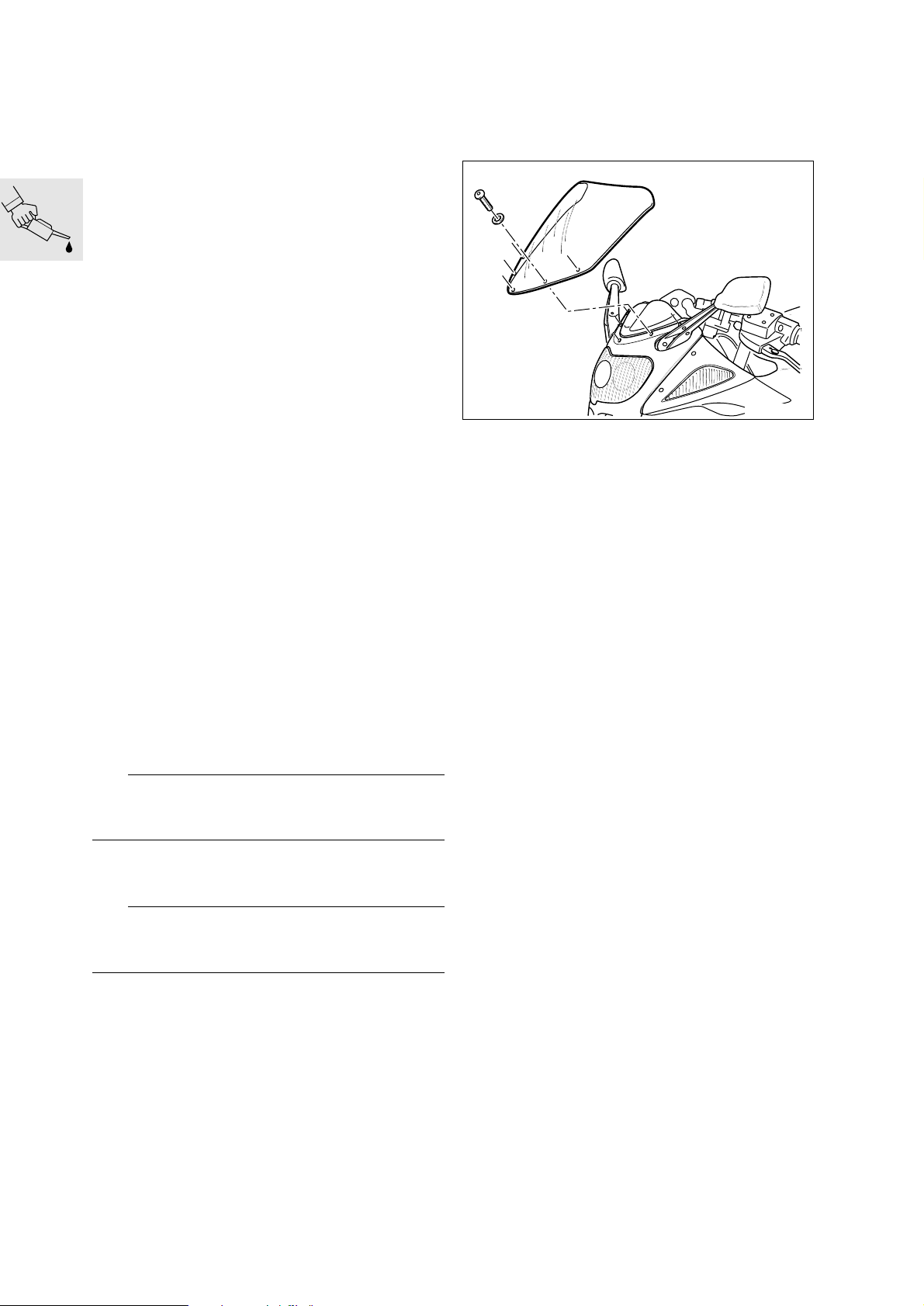
– Windscreen and securing screws
Pry off the cross struts with a suitable lever.
•
e Caution:
Do not hammer out the cross struts or the motorcycle may be damaged.
Installing remaining items on motorcycle
Wheel the motorcycle clear of the wooden pallet.
•
S000030
Carefully tighten the securing screws by hand.
•
Inspecting motorcycle for damage
Check for defects.
•
Send an “Urgent notification” to
•
BMW AG, Sparte Motorrad, UX-VS-1
Fax No. +49 89 382 33220
Rectify the defect.
•
Use the electronic parts list to order parts, if
•
needed.
Costs are to be processed by the warranty claim
•
system (stage 4). Defect codes:
– Parts missing 10 01 00 00 00
– Parts damaged 10 02 00 00 00
– Incorrect parts delivered 10 03 00 00 00
If the parts that are needed do not appear in the
•
electronic parts list (e.g. parts for official-user
motorcycles), send an order form to:
Fax No. +49 30-3396-2262
Checking that delivery is complete
Remove the end panels.
•
Remove the side panels.
•
e Caution:
Remove all nails projecting from the base of the
crate or lying on the floor.
Dispose of the packing materials in an environ-
•
mentally responsible manner as described in
Service Information 23/91 - Sales.
00.14
– All optional extras
– Toolkit
– Documentation
Page 23
S000020
Filling and charging the battery
Disengaging and raising the fuel tank
Remove seat.
•
Remove right and left side trim panels.
•
e Caution:
Fuel is flammable and a hazard to health. Observe
relevant safety regulations.
Remove the fuel tank.
•
Raise the rear of the fuel tank and prop it in this
•
position on a wooden block or similar.
Filling and charging the battery
d Warning:
Battery acid is severely caustic.
Protect your eyes, face, hands and clothing and the
paintwork.
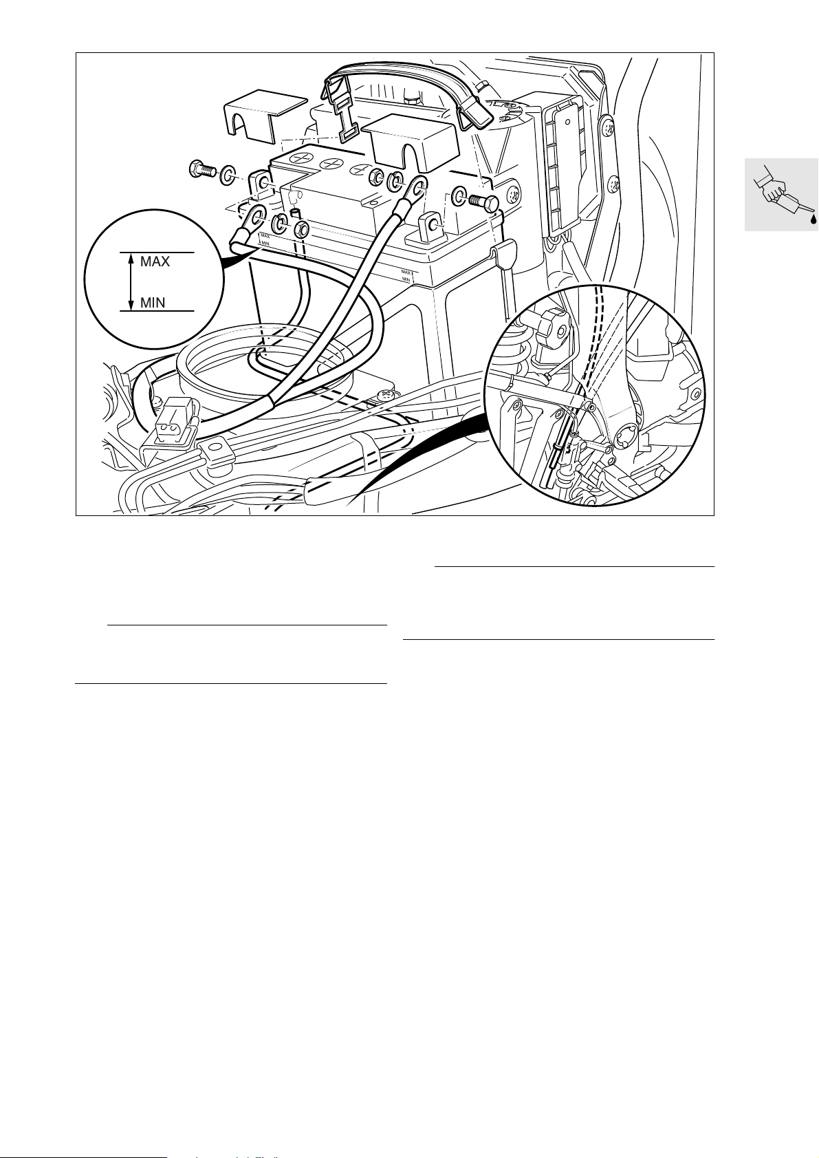
Disengage the rubber strap holding the battery.
•
Disconnect the battery breather hose.
•
Remove the battery.
•
Add battery acid up to the MAX mark.
•
Allow the battery to stand for at least an hour.
•
Shake the battery slightly to allow the remaining
•
air bubbles to escape.
If necessary, top up again to the MAX mark with
•
battery acid.
Charge the battery and allow to stand for
•
24 hours.
Charge current (amps)
......................... 10 % of rated battery capacity (Ah)
If necessary, top up the acid level to the MAX
•
mark with distilled water.
Make a note of the charging date on the battery.
•
00.15
Page 24

e Caution:
Connect the positive battery terminal first, then the
negative terminal.
Apply acid-proof grease to the battery terminal
•
posts.
Install the battery.
•
Secure the fuel tank in position.
•
Install right and left side trim panels.
•
Install dualseat.
•
Switch on the ignition.
•
Without starting the engine, fully open the throttle
•
once or twice so that the Motronic control unit
can register the throttle-valve positions.
L Note:
Disconnecting the battery deletes all entries (e.g.
faults, settings) stored in the Motronic control unit’s
memory.
Loss of settings can temporarily impair the operating characteristics when the engine is restarted.
X Tightening torque:
Fuel tank to rear frame ................................. 10 Nm
Checking engine oil level when
cold, adding oil if necessary
MAX
MIN
S000040
Check the oil level with the motorcycle upright: if
•
necessary, use stand, BMW No. 00 1 560, to
keep the motorcycle in the upright position.
e Caution:
Never top up the engine-oil level past the MAX mark.
Required level:............................................... MAX
00.16
Page 25
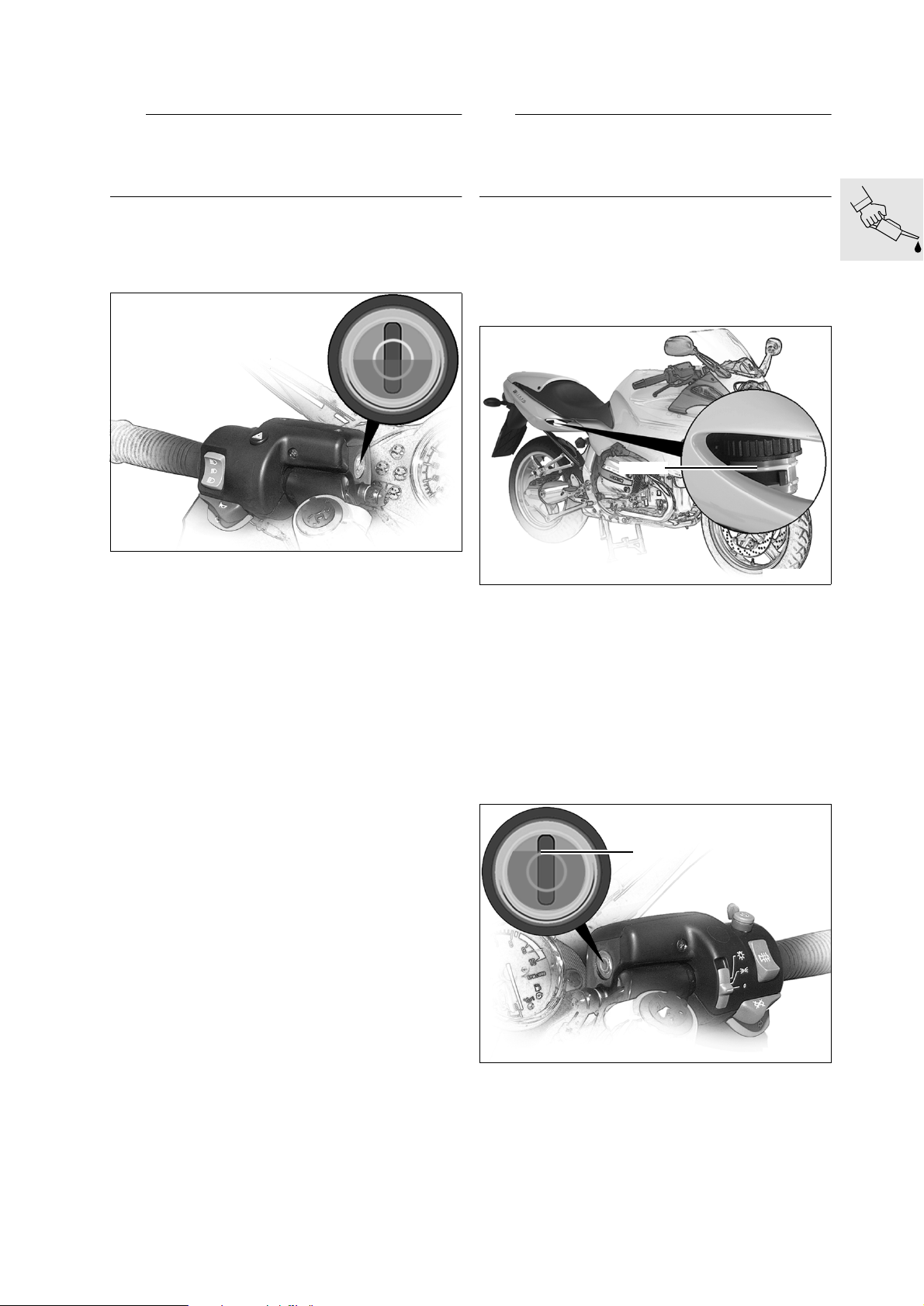
Checking clutch fluid level
Checking brake fluid level
e Caution:
Keep the brake fluid in the clutch operating system
away from painted surfaces on the motorcycle because brake fluid attacks paint.
Motorcycle upright; if necessary, use stand,
•
BMW No. 00 1 560, to hold the motorcycle upright.
Turn the handlebar fully to the right.
•
S000050
Check clutch fluid level.
•
e Caution:
Do not allow brake fluid to come into contact with
painted parts of the motorcycle, because brake fluid
attacks paint.
Rear brake
Motorcycle upright; if necessary, use stand,
•
BMWNo.001560, to hold the motorcycle upright.
MAX
S000060
Required level with a new clutch liner: ................
...........................................Half way up sight glass
Check the brake fluid level by looking through
•
the opening in the right-hand side panel.
Required level:............................................... MAX
Front brake
Motorcycle upright; if necessary, use stand,
•
BMWNo.001560, to hold the motorcycle upright.
Handlebar centred.
•
MAX
S000071
Required level:............................................... MAX
00.17
Page 26
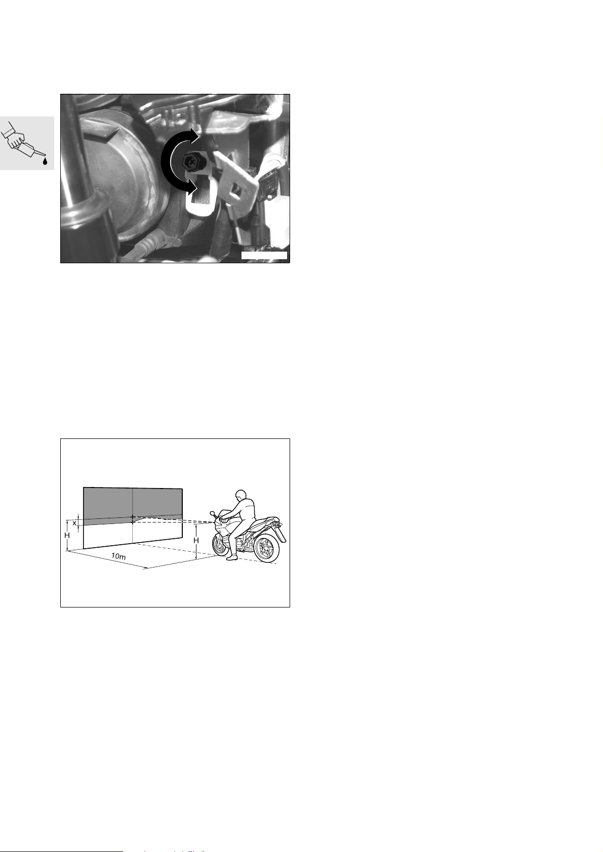
Checking headlight beam angle,
adjusting if necessary
S000240
Motorcycle on level surface.
•
Rider’s weight on motorcycle (approx. 80 kg/
•
176 lbs).
Move swivel lever to horizontal position (basic
•
setting).
Turn the adjusting screw to correct the headlight
•
beam throw.
Checking tightness of rear wheel studs
X Tightening torque:
Rear wheel studs ....................................... 105 Nm
Checking tyre pressures
Check/correct tyre pressures.
•
Tyre pressures:
Solo ..................................... front 2.2 bar (31.3 psi)
.............................................rear 2.5 bar (35.6 psi)
Two-up ................................ front 2.5 bar (35.6 psi)
.............................................rear 2.7 bar (38.4 psi)
Two-up + luggage................ front 2.5 bar (35.6 psi)
.............................................rear 2.9 bar (41.2 psi)
Lateral adjustment:
........................Adjusting screw on left of headlight
Vertical adjustment:
......................Adjusting screw on right of headlight
Turn screw anti-clockwise: ...............longer throw
Turn screw clockwise: .....................shorter throw
S000080
Setting for headlight beam angle adjuster
.... -12 cm (4.7 in) over a distance of 10 m (32.8 ft)
00.18
Page 27

Final inspection and function check
Handing over the motorcycle
Clutch
•
Check gear shift action.
•
Handbrake and foot brake
•
Check lights and signalling equipment:
•
– Front and rear parking lights
– Instrument lighting
– Low and high headlight beams, headlight flasher
– Brake light (operate front and rear brakes)
– Turn signals left/right
– Hazard warning flashers
–Horn
– Telltale and warning lights
– Instruments
Check function of optional extras:
•
– ABS: perform starting test. When a speed of
5 km/h (app. 3 mile/h) is reached, both
ABS warning lights must go out.
If necessary, take the motorcycle for a test ride.
•
Confirm pre-delivery check in Service and Tech-
•
nical booklet.
See “Inspecting motorcycle for damage” if de-
•
fects are detected.
Final cleaning
Clean the motorcycle.
•
L Note:
Do not use a steam or high-pressure water jet. The
high steam or water pressure could damage seals,
the hydraulic system or electrical components.
This is the ideal opportunity to familiarise the customer with the motorcycle in order to ensure the
customer’s satisfaction and safety.
The following points must be demonstrated and
•
explained to the customer:
– documentation and stowage space
– toolkit and stowage space
– suspension preload adjustment to suit total
weight
– checking brake fluid/clutch operating fluid
– provision for adjusting handlebar lever positions
– how to adjust the mirrors
– controls
– instruments and telltale lights
– optional equipment and accessories fitted.
– noise during the regular ABS self-diagnosis pro-
cedure
The user must be given the following information:
•
– running-in recommendations and inspection in-
tervals
– safety check
– the clutch fluid level rises gradually as the motor-
cycle is ridden (clutch lining wear)
– before checking the engine oil level, the engine
must be switched off for at least 10 minutes and
the motorcycle must be standing on a flat, level
surface
00.19
Page 28
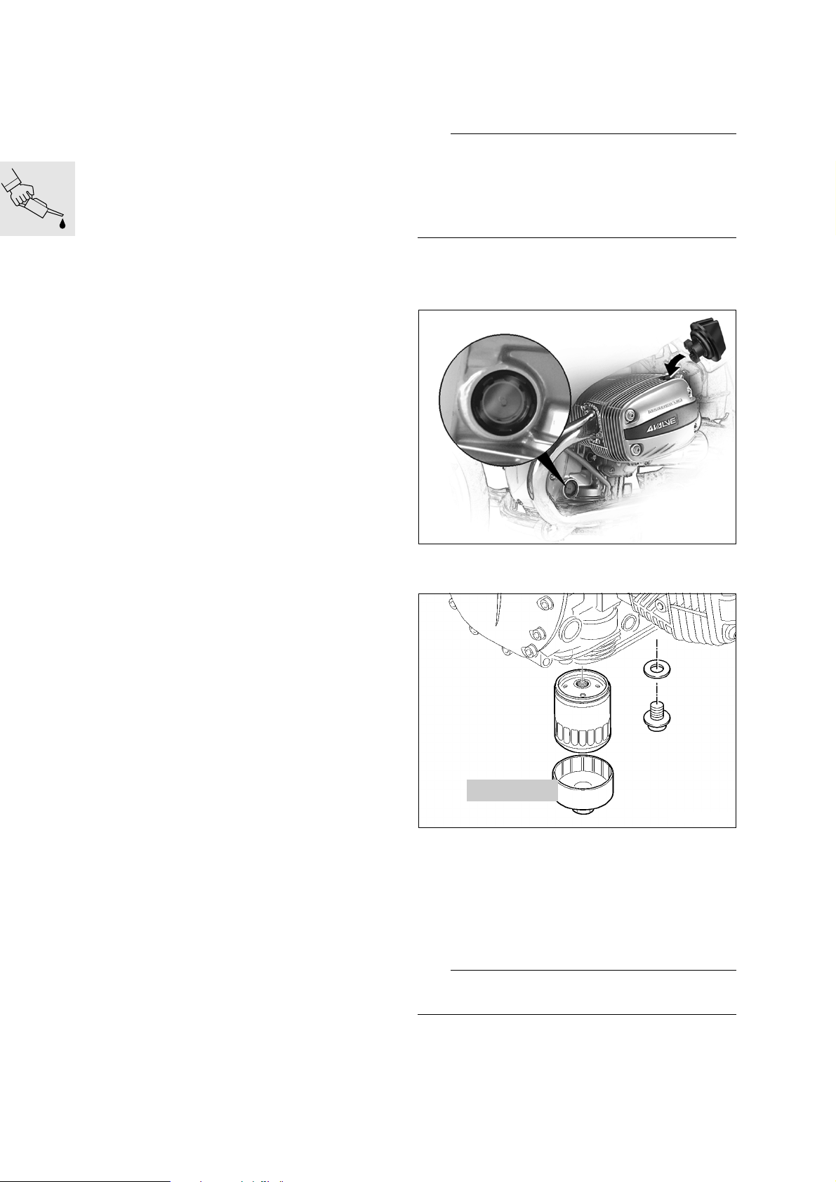
Maintenance
Key to maintenance intervals
– BMW Inspection 1000 km/600 miles I
– BMW Service II
– BMW Inspection III
– BMW Annual Service IV
Reading out MoDiTeC fault memory
Changing engine oil, replacing oil filter element
(Inspections I, II, III and IV)
L Note:
If the motorcycle is ridden only for short distances or
outside temperatures are below 0°C (32°F): change
the oil and replace the oil filter element every
3 months or no later than every 3 000 km
(1 800 miles).
(Inspections I, II, III and IV)
Remove seat.
•
Connect the BMW MoDiTeC to the diagnosis
•
connector.
Read out the fault memory.
•
Perform all requisite repair work.
•
Use the auxiliary stand, BMWNo.001560, if
•
necessary.
Change the oil at operating temperature.
•
Remove screw plug.
•
S000040
00.20
11 4 650
C000030
Remove oil drain plug and drain off oil.
•
Fit new seal and screw in drain plug.
•
Use oil filter wrench, BMW No. 11 4 650, to re-
•
move the oil filter.
Coat sealing ring on new oil filter element with oil
•
and install filter.
Refill with oil to correct level.
•
Insert and tighten the screw plug.
•
e Caution:
Never top up the engine oil level past the MAX mark.
X Tightening torque:
Oil filter......................................................... 11 Nm
Oil drain plug................................................ 32 Nm
Page 29
Engine oil quantities:
With oil filter
change..........3.75 l (6.6 Imp. pints/3.96 US quarts)
Without oil filter
change..........3.50 l (6.2 Imp. pints/3.69 US quarts)
Difference between MIN and MAX
marks............. 0.50 l (0.88 Imp. pint/0.52 US quart)
Engine oil grade:
Brand-name HD oil for spark-ignition engines, API
classifications SF, SG, SH; combination with CD or
CE specification.
Brand-name HD oil of CCMC classification G4, G5;
amendment PD2 is permissible.
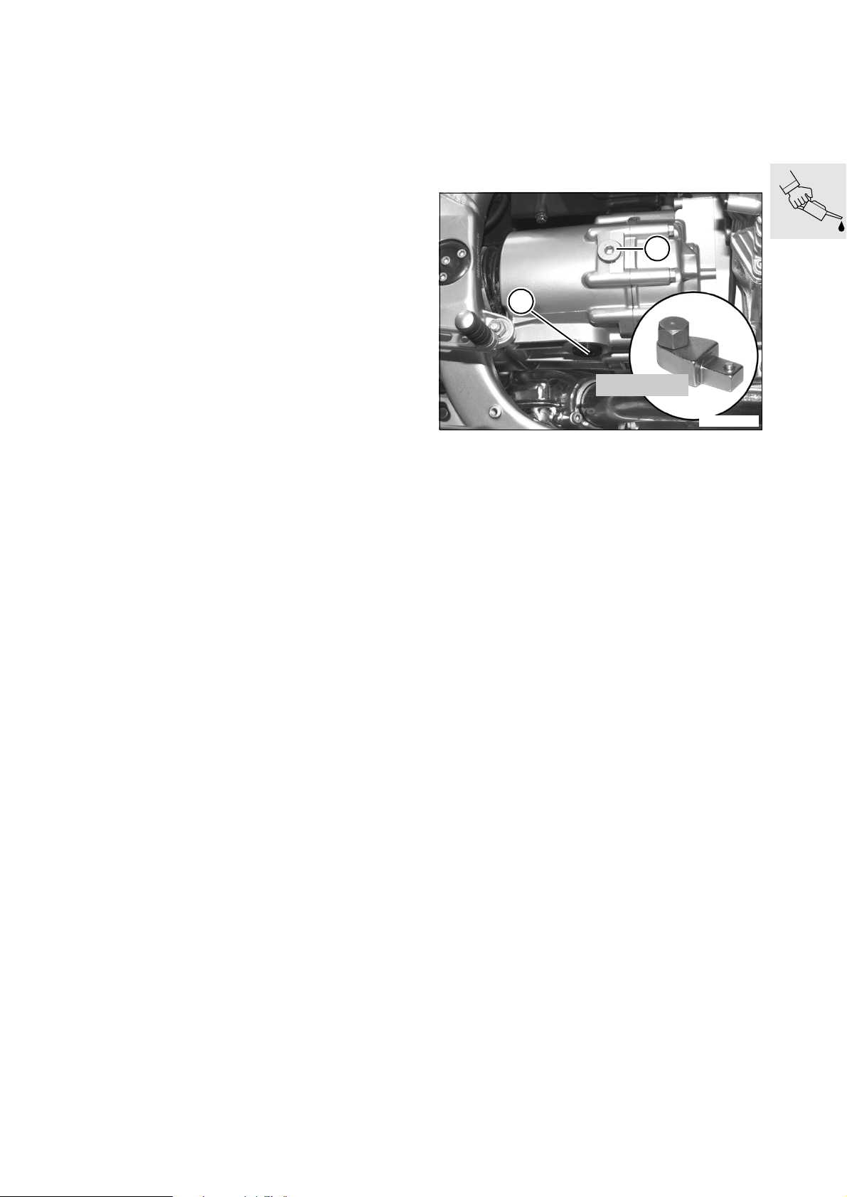
Changing oil in gearbox
(Inspections III and IV)
or every 2 years at the latest
Change the gearbox oil at operating tempera-
•
ture.
1
2
23 4 690
S000120
Remove oil filler plug (1).
•
Use socket-head key, BMW No. 23 4 690 and
•
torque wrench, to remove oil drain plug (2) and
drain the oil into a suitable container.
Clean the magnet in the oil drain plug.
•
Fit new seal and reinstall drain plug.
•
Refill with gearbox oil to correct level.
•
Insert oil filler plug with new seal.
•
X Tightening torque:
Oil drain plug................................................ 55 Nm
Oil filler plug ................................................. 23 Nm
Quantity:
Initial filling/oil changes
..........approx. 0.8 l (1.40 Imp. pint, 0.84 US quart)
Oil grade for gearbox:
Brand-name hypoid gear oil, SAE 90, API class GL 5
00.21
Page 30
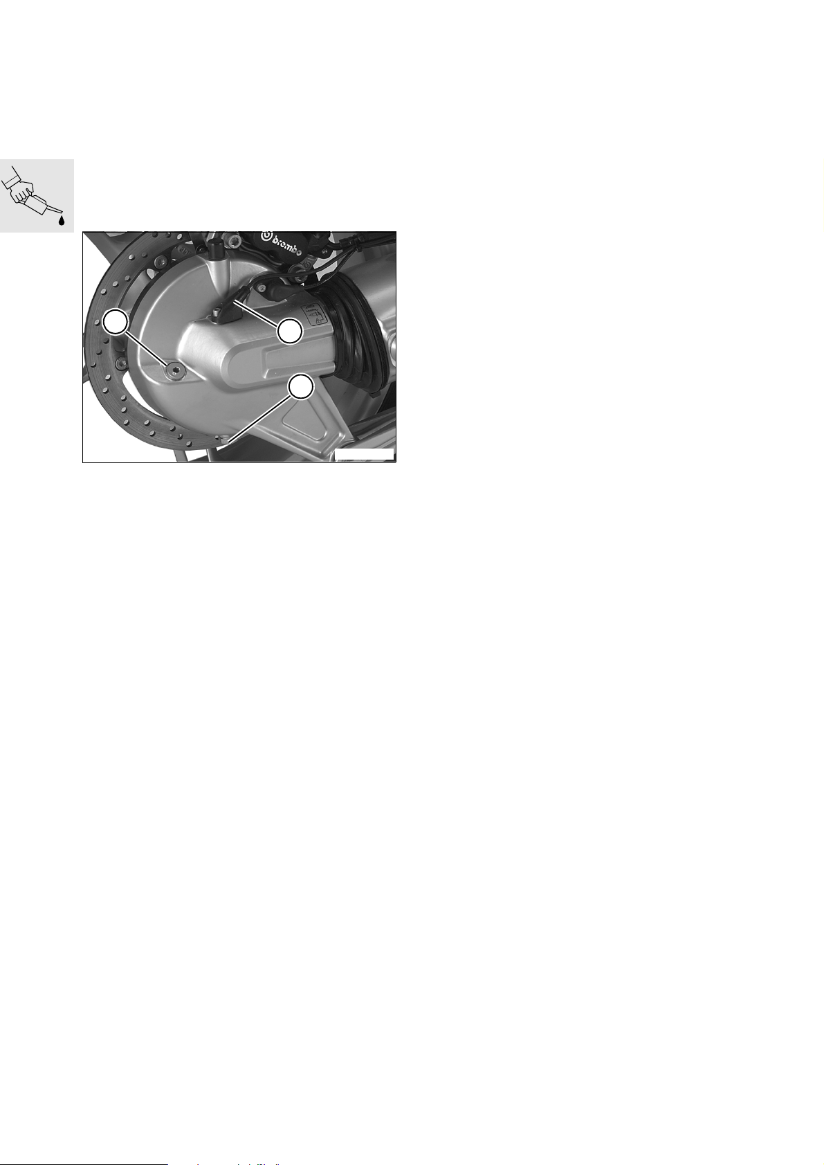
Changing oil in rear wheel drive;
cleaning inductive signal transmitter
at rear wheel
(Inspections I, III and IV)
Every 40 000 km (24 000 miles) or every 2 years
at the latest
Change the oil with the rear wheel drive at oper-
•
ating temperature.
1
3
2
S000130
Remove oil filler plug (1).
•
Remove oil drain plug (2) and allow the oil to
•
drain out.
Fit new seal and reinstall drain plug.
•
Refill with gearbox oil to correct level.
•
Insert oil filler plug with new seal.
•
Remove securing screw, pull out inductive signal
•
transmitter (3) and clean it.
X Tightening torque:
Oil drain plug................................................23 Nm
Oil filler plug ................................................. 23 Nm
Quantity:
To bottom edge of the filler opening
..........approx. 0.25 l (0.44 Imp. pint/0.26 US quart)
Oil grade for rear wheel drive:
Brand-name hypoid gear oil, SAE 90, API class GL 5
00.22
Page 31
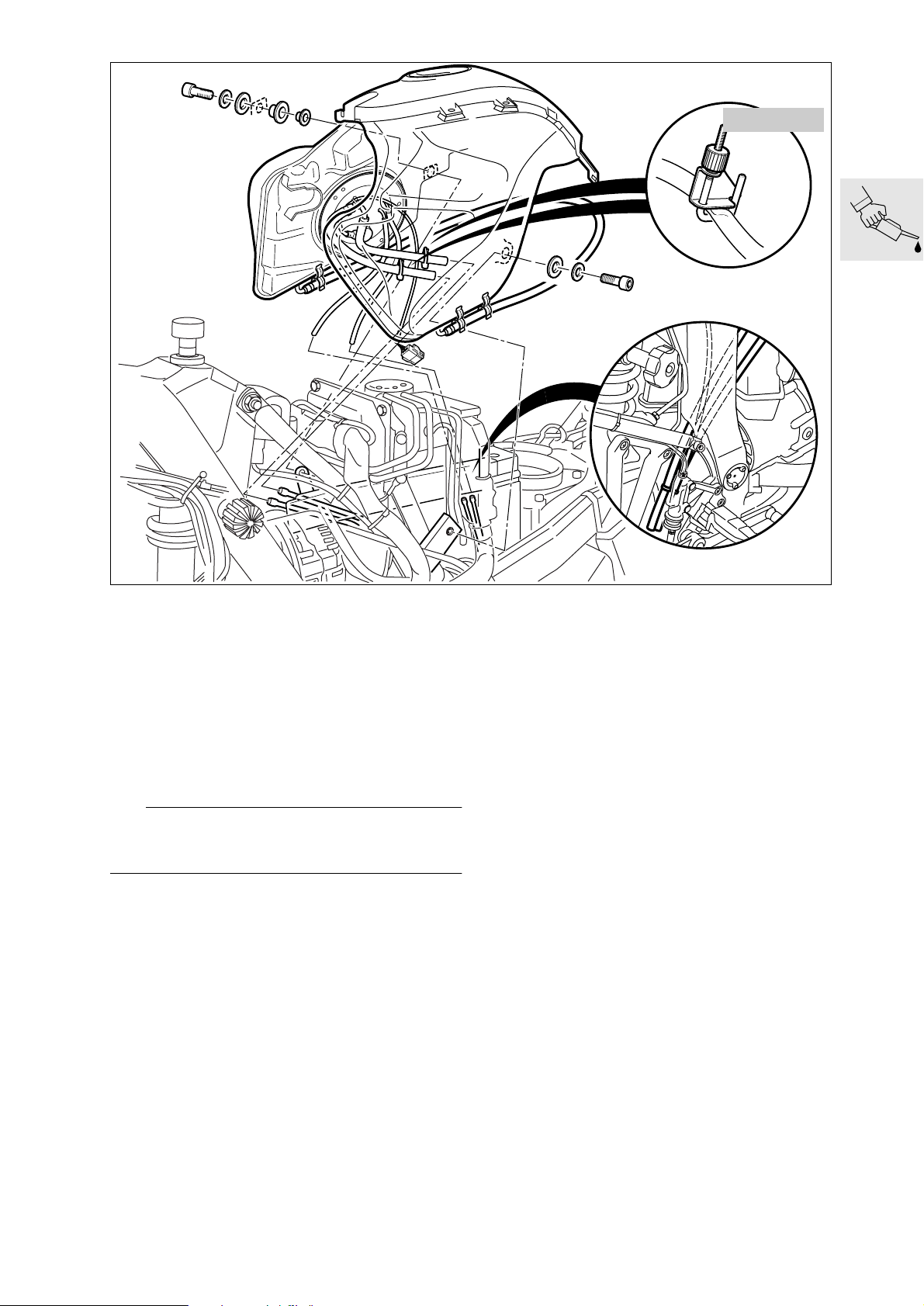
13 3 010
Replacing fuel filter
(Inspection III)
In normal operating conditions every 40 000 km
(24 000 miles); if fuel quality is poor every
20 000 km (12 000 miles)
Remove seat.
•
Remove left fairing side section, followed by right
•
fairing side section.
Disconnect air intake pipe from air filter box and
•
remove.
e Caution:
Fuel is flammable and a hazard to health. Observe
relevant safety regulations.
Disengage the fuel tank.
•
Seal the fuel feed and return lines with hose
•
clips, BMW No. 13 3 010, and disconnect.
Pull the plug connector off the fuel pump unit.
•
Remove the fuel tank.
•
S160010
00.23
Page 32
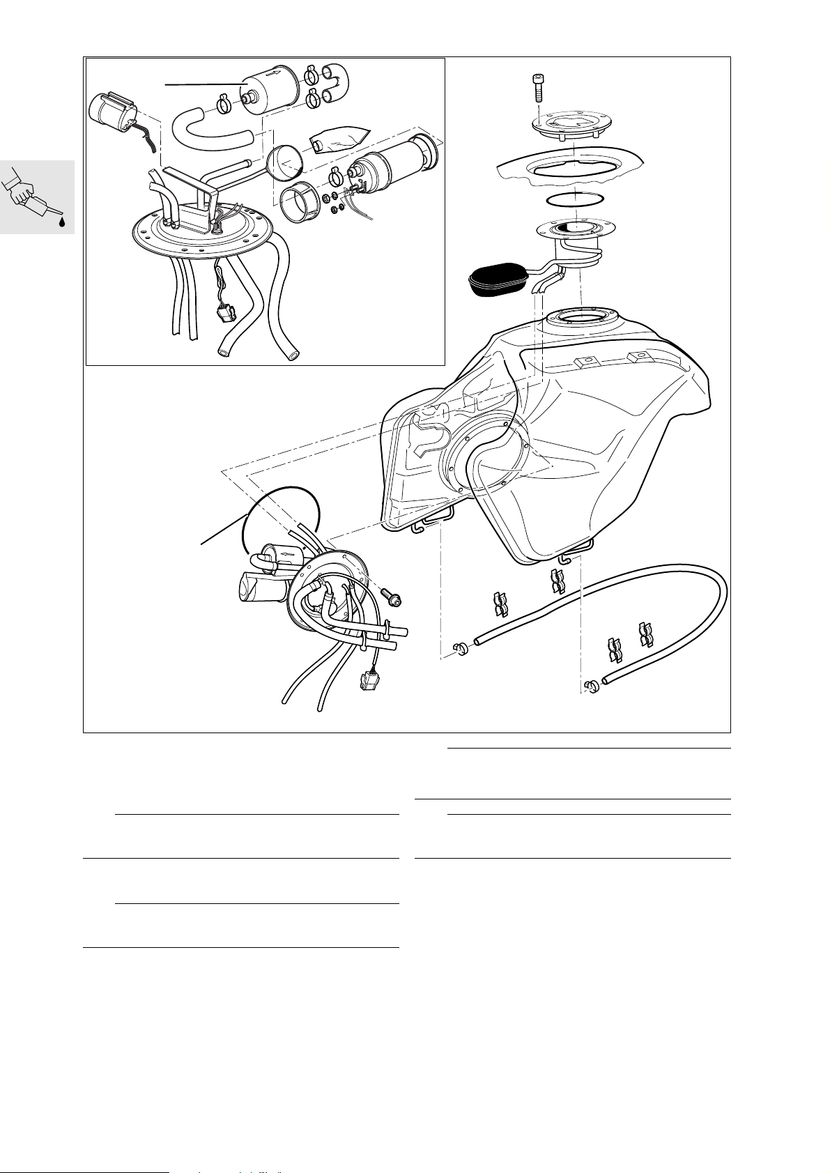
1
2
Drain fuel tank.
•
Remove fuel pump unit.
•
Disconnect hoses from fuel filter (1).
•
Fit new fuel filter.
•
e Caution:
Note correct direction of flow through fuel filter.
Secure non-reusable hose clips with pliers,
•
BMW No. 13 1 500.
e Caution:
Make sure that O-ring (2) is in perfect condition.
S160020
e Caution:
After installing, check fuel pump unit for leaks.
L Note:
Make sure that breather lines are correctly routed.
X Tightening torque:
Fuel pump unit .............................................. 5 Nm
00.24
Page 33
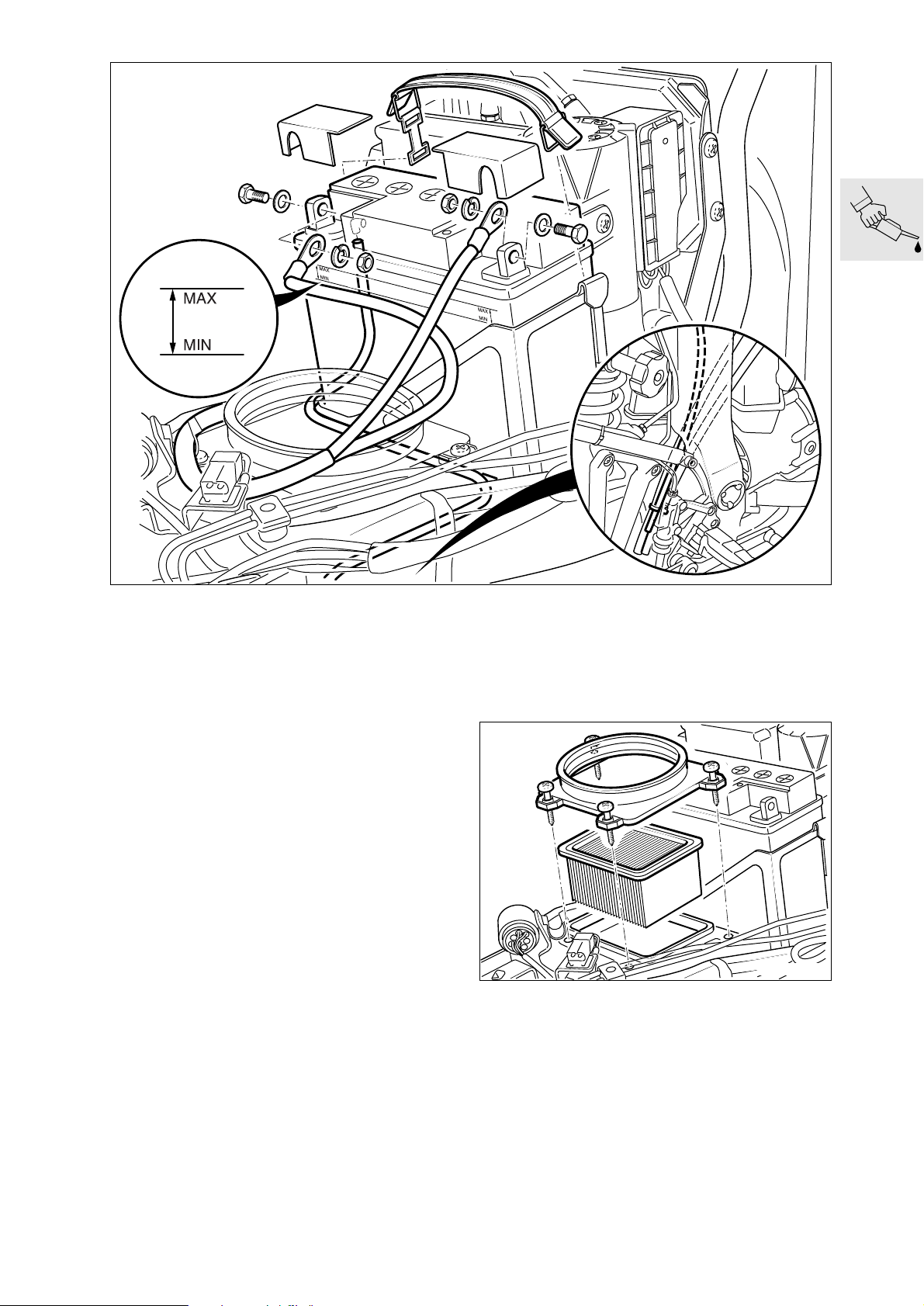
S000020
Checking battery fluid level and
topping up if necessary; cleaning and
greasing the battery posts
(Inspections III and IV)
If necessary, disengage fuel tank and lift at rear.
•
Release the rubber strap holding the battery.
•
Check the battery fluid level.
•
Top up the acid level to the MAX mark with dis-
•
tilled water.
Grease the battery posts.
•
Acid-proof battery-post grease:
................................................e.g. Bosch Ft 40 V1
Replacing intake air filter element
(Inspection III)
In very dirty and dusty operating conditions,
replace every 10 000 km (6 000 miles) or even
more frequently if necessary
S000010
Remove top of air-filter housing.
•
Replace air filter element.
•
Install the fuel tank.
•
Make sure that breather lines are correctly rout-
•
ed.
Install right and left side trim panels.
•
X Tightening torque:
Fuel tank to rear frame ................................. 10 Nm
00.25
Page 34
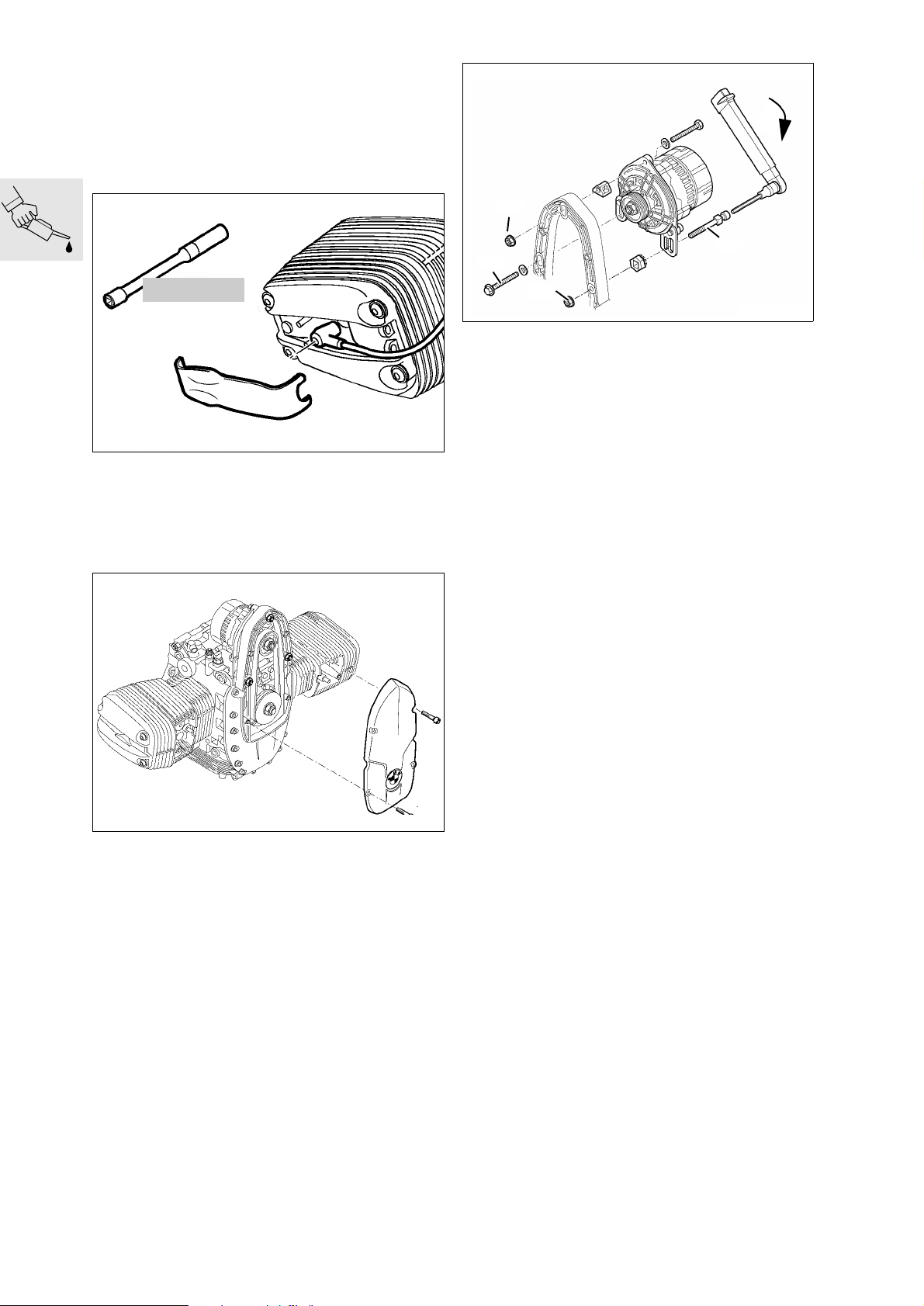
Replacing Poly-V belt
(every 60 000 km/36 000 miles)
(Inspection III)
If necessary, disengage fuel tank and pull to the
•
rear.
3
12 3 510
C000060
Remove cover to expose spark plug caps.
•
Pull off spark plug caps with special puller,
•
BMWNo.123520.
Use spark plug wrench, BMW No. 12 3 510, to
•
remove the spark plugs.
4
2
1
RS110480
Slacken alternator mounting screws and
•
nuts (1,3,4) and install a new Poly-V belt if necessary.
Poly-V belt adjusting procedure:
Poly-V belt installation procedure:
Place the Poly-V belt in position, tension it and
•
turn the engine over once, then release belt tension.
Poly-V belt tensioning procedure:
1. Hand-tighten hex nut (1) on adjusting screw (2)
(do no use tools).
2. Tighten adjusting screw (2) with a torque wrench
and keep preload applied.
3. Tighten upper retaining nut (3), then remove
torque wrench from adjusting screw.
4. Tighten all screws and nuts.
Tightening torque:
Poly-V belt preload......................................... 8 Nm
Alternator to alternator support cover........... 20 Nm
Remove front cover.
•
00.26
RS110490
Page 35
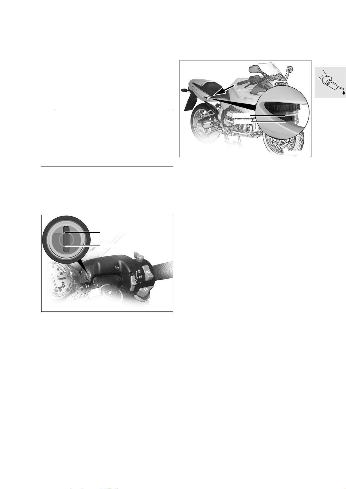
Checking brake system for correct
operation and freedom from leaks;
repairing/replacing if necessary
(Inspection III)
Checking brake system for leaks.
•
Checking brake fluid level
(Inspections I, II and III)
Rear brake
Motorcycle upright; if necessary, use stand,
•
BMWNo.001560, to hold the motorcycle up-
right.
L Note:
The brake fluid volume (between MIN and MAX) is
sufficient for the complete range of pad wear from
new to the wear limit.
It is not normally necessary to top up the fluid to accommodate pad wear.
If the level drops below the minimum mark, this indicates some other fault.
Front brake
Motorcycle upright; if necessary, use stand,
•
BMW No. 00 1 560, to hold the motorcycle upright.
MAX
MIN
MAX
MIN
S000060
Required level
Brake pads new:............................................. MAX
Brake pads worn: not less than........................ MIN
Brake fluid grade.........................................DOT 4
S000070
Handlebar centred.
•
Required level
Brake pads new.............................................. MAX
Turn the handlebar fully to the left.
•
Required level
Brake pads worn: not less than........................ MIN
Brake fluid grade .........................................DOT 4
00.27
Page 36
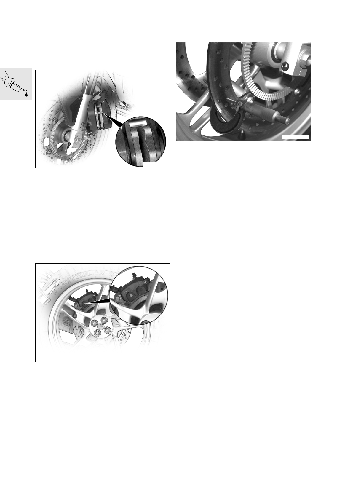
Checking brake pads and discs for wear/replacing
(Inspections II and III)
Checking front brake pad wear
S000140
Check/measure thickness of brake pads.
•
e Caution:
Never permit brake pads to wear past the minimum
permissible thickness.
Always replace the brake pads as a complete set.
Checking brake disc wear
S000160
Examine the brake discs carefully for cracks,
•
damage, distortion, wear and score-marks.
Brake disc wear limit:
front:............................................. 4.0 mm (0.16 in)
rear:.............................................. 4.5 mm (0.18 in)
Minimum pad thickness: ............. 1.0 mm (0.04 in)
Checking rear brake pad wear
S000150
Make sure that the brake disc is not visible
•
through the bore (arrow) in the inner brake pad.
If necessary, check/measure thickness of brake
•
pads.
e Caution:
Never permit brake pads to wear past the minimum
permissible thickness.
Always replace the brake pads as a complete set.
Minimum pad thickness: ............. 1.5 mm (0.06 in)
00.28
Page 37
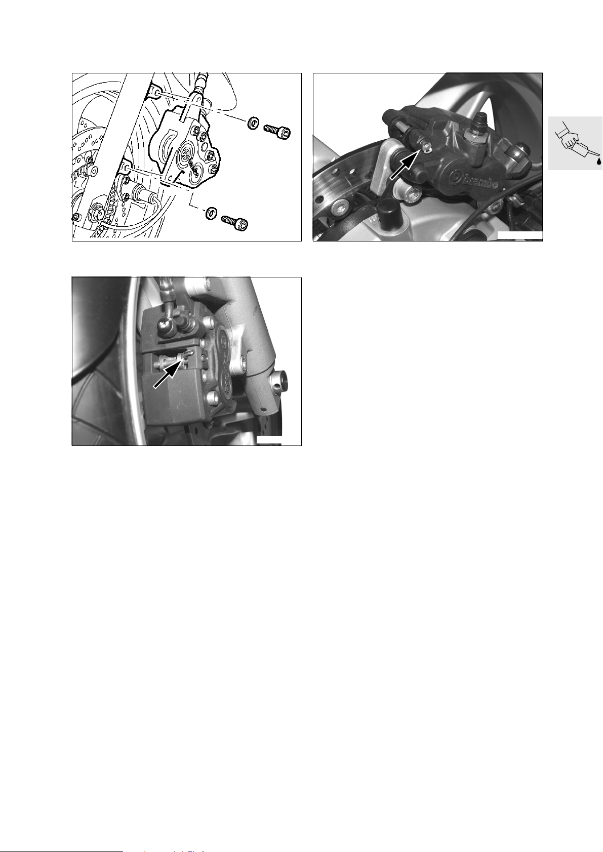
Replacing brake pads, front brake
Replacing brake pads, rear brake
RS340021
Remove brake caliper.
•
S000170
Remove keeper (arrow) from retaining pin.
•
Drive out retaining pin.
•
Remove brake pads.
•
Installation is the reverse of the removal proce-
•
dure.
Before installing the brake caliper, force the pis-
•
tons fully back with resetting tool,
BMW No. 34 1 500.
S000180
Remove brake caliper.
•
Remove keeper (arrow) from retaining pin.
•
Drive the retaining pin out towards the wheel
•
side.
Remove brake pads.
•
Installation is the reverse of the removal proce-
•
dure.
Before installing the brake caliper, force the pis-
•
tons fully back.
X Tightening torque:
Brake caliper to rear wheel drive.................. 40 Nm
X Tightening torque:
Brake caliper to fork slider tube.................... 40 Nm
00.29
Page 38
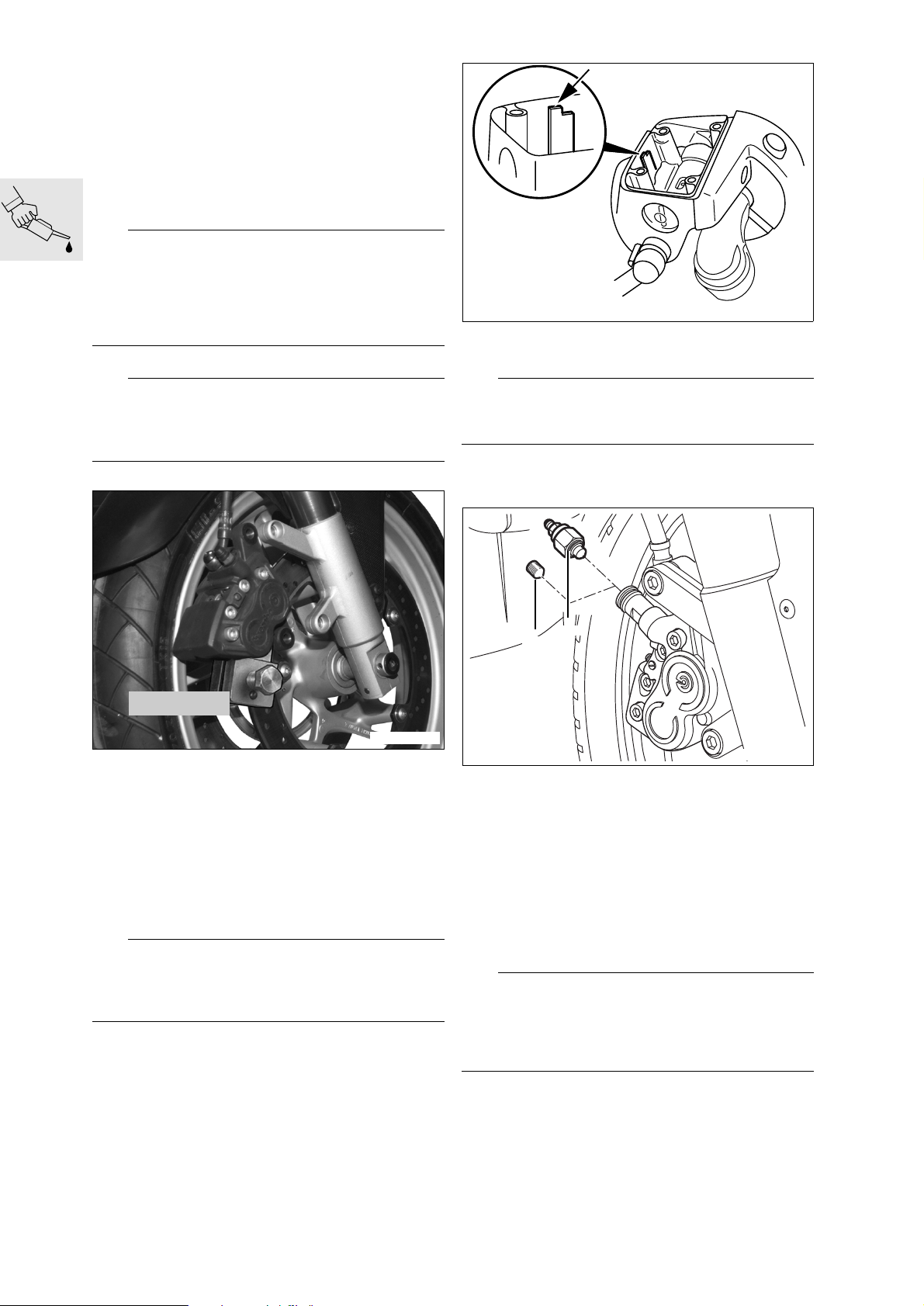
Changing brake fluid and bleeding brake system
Change the brake fluid annually
(Inspection IV)
Bleeding front brake circuit/changing brake fluid
L Note:
This description applies to brake filling and bleeding
devices with vacuum extraction of the brake fluid at
the brake caliper.
If other devices are used, comply with their manufacturers’ instructions.
Remove brake calipers.
•
KR340280
Top up the brake fluid level to the MAX mark (ar-
•
row).
e Caution:
Keep the brake caliper parallel to the brake disc
when removing and installing.
There is a risk of damage to the brake pads.
Remove the brake pads.
•
34 1 500
S000190
Use resetting tool, BMWNo.341500, to force
•
the pistons of the right-hand brake caliper fully
back.
Turn the handlebars to the left.
•
Release the right handlebar switch.
•
Loosen the clamp screw for the handbrake fitting
•
and turn the fitting until the brake fluid reservoir
is horizontal.
Tighten the clamping screw.
•
Remove reservoir cover with rubber diaphragm.
•
e Caution:
Do not allow brake fluid to come into contact with
painted parts of the motorcycle, because brake fluid
attacks paint.
e Caution:
When adding brake fluid, do not allow it to enter the
holes for the reservoir cover screws.
[ABS] Begin by bleeding the pressure modula-
•
tor.
a ..............See Additional information for [ABS]
2
1
S000261
Wrap a cloth around the filler adapter in the right
•
brake calliper.
Remove socket-head grub screw (1) from the fill-
•
er adapter in the right brake calliper.
Connect the brake bleeding device to bleed
•
screw (2).
Fully tighten the bleed screw in the filler adapter
•
(valve in filler adapter closed).
Open the bleed screw by half a turn (valve open).
•
Draw off brake fluid until it emerges clear and
•
free from air bubbles.
e Caution:
While bleeding the brakes, do not allow the brake
fluid level to drop below the “MIN” mark, or else air
will be drawn into the brake system.
Bleed the system again if this happens.
00.30
Remove the bleed screw.
•
Disconnect the brake bleeding device from the
•
bleed screw.
Page 39
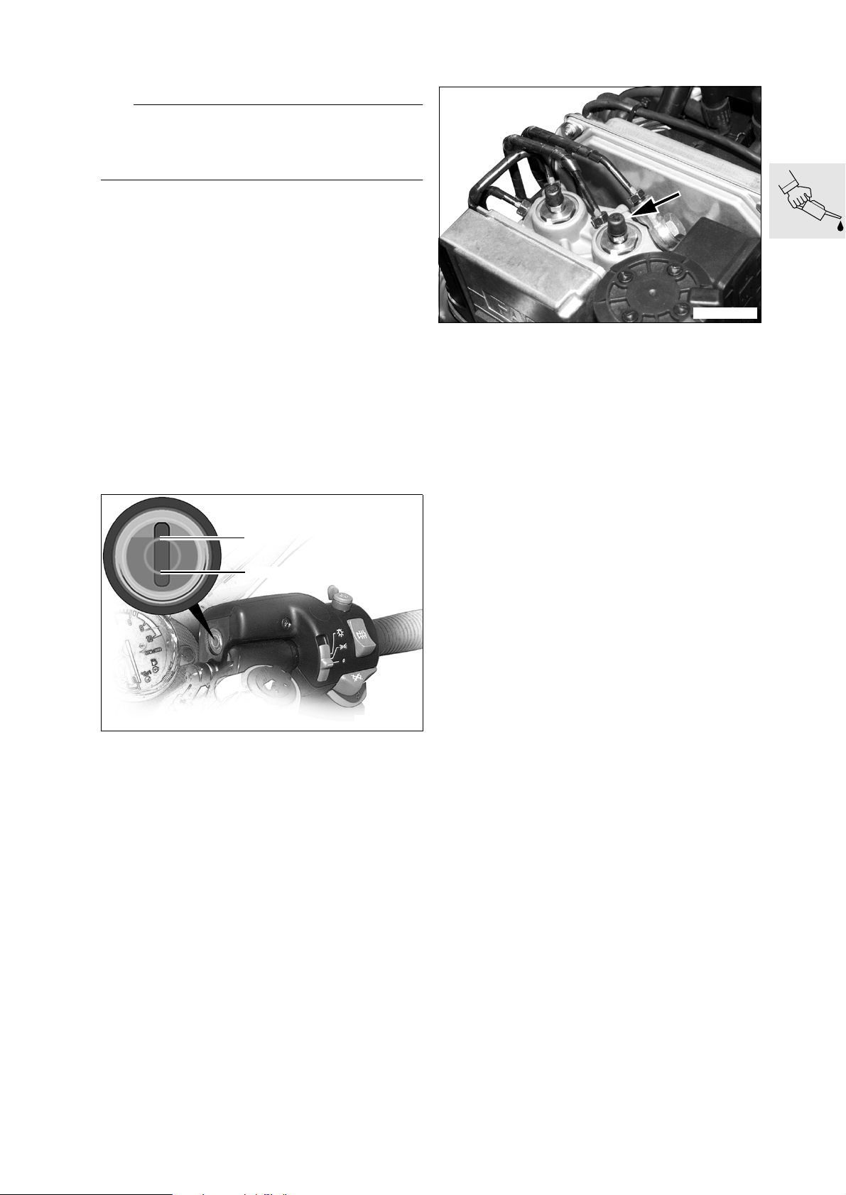
Install socket-head grub screw (1) in the filler
•
adapter and tighten.
e Caution:
The motorcycle is not permitted on the road without
the grubscrew in place and secure in the filler adapter.
Connect the brake bleeding device to the bleed
•
screw of the left-hand brake caliper.
Open the bleed screw a half turn.
•
Draw off brake fluid until it emerges clear and
•
free from air bubbles.
Close the bleed screw.
•
Assembly is the reverse of the disassembly pro-
•
cedure.
Top up the brake fluid until the level reaches the
•
“MAX” mark.
Wipe the rim of the reservoir, the rubber gaiter
•
and the cover to remove brake fluid, and carefully
re-install the components.
Align the handbrake fitting with the mark on the
•
handlebar.
Recheck the brake-fluid level.
•
Motorcycle upright; if necessary, use stand,
•
BMW No. 00 1 560, to hold the motorcycle up-
right.
Additional information for [ABS]
S000200
Before bleeding the brake caliper, connect the
•
brake bleeding device to the bleed screw on the
pressure modulator for the front brake (arrow)
marked VR (mark for rear brake is HR).
Open the bleed screw by half a turn.
•
Draw off brake fluid until it emerges clear and
•
free from air bubbles.
Close the bleed screw.
•
X Tightening torque:
Bleed screw in pressure modulator................ 9 Nm
MAX
MIN
S000071
Handlebar centred.
•
Required level
Brake pads new.............................................. MAX
Turn the handlebar fully to the left.
•
Required level
Brake pads worn: not less than........................ MIN
Check the function of the brake system.
•
Brake fluid grade .........................................DOT 4
X Tightening torque:
Brake caliper to fork tube............................. 40 Nm
Grubscrew in filler adapter ........................... 10 Nm
Bleed screw in front brake caliper................ 14 Nm
00.31
Page 40
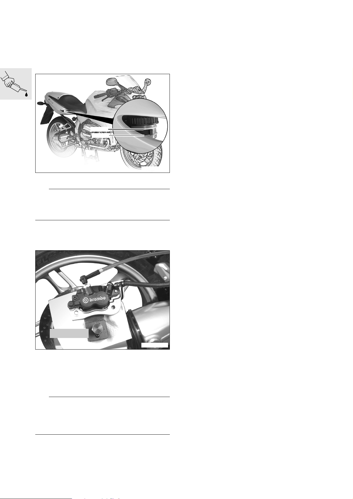
Bleeding rear brake circuit/changing brake fluid
[ABS] Begin by bleeding the pressure modula-
•
tor.
a ..............See Additional information for [ABS]
Use the auxiliary stand, BMW No. 00 1 560.
•
Remove reservoir cover.
•
MAX
MIN
S000060
Top up the brake fluid level to the “MAX” mark.
•
e Caution:
Do not allow brake fluid to come into contact with
painted parts of the motorcycle, because brake fluid
attacks paint.
Assembly is the reverse of the disassembly pro-
•
cedure.
Check the function of the brake system.
•
Brake fluid grade .........................................DOT 4
X Tightening torque:
Bleed screw in rear brake caliper ................... 6 Nm
Brake caliper to rear wheel drive.................. 40 Nm
Remove the brake caliper.
•
Remove the inner brake pad.
•
Move the brake caliper to a horizontal position.
•
34 1 500
S000210
Force the pistons fully back with resetting tool,
•
BMWNo. 341500.
Connect the brake bleeding device and open the
•
bleed screw.
Draw off brake fluid until it emerges clear and
•
free from air bubbles.
e Caution:
While bleeding the brakes, do not allow the brake
fluid level to drop below the “MIN” mark, or else air
will be drawn into the brake system.
Bleed the system again if this happens.
Close the bleed screw.
•
Top up the brake fluid level to the “MAX” mark.
•
00.32
Page 41
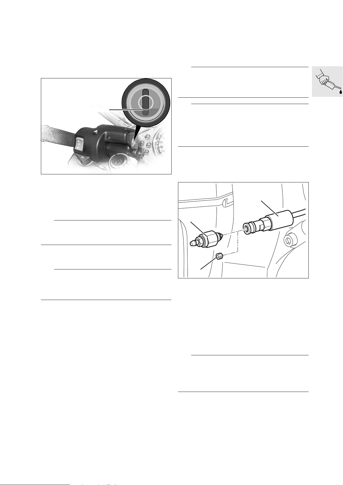
Checking clutch fluid level
Changing the clutch fluid
(Inspections I, II and III)
Place the motorcycle on the auxiliary stand,
•
BMW No. 00 1 560.
Turn the handlebars to the right.
•
MIN
S000051
Fluid level:
not below ......................................................... MIN
Required level with a
new clutch liner: ................Half way up sight glass
L Note:
As the clutch lining wears, the fluid level in the reservoir rises.
(Inspections III and IV)
Every 40 000 km (24 000 miles) or every 2 years
at the latest
e Caution:
Do not allow brake fluid to come into contact with
painted parts of the motorcycle, because brake fluid
attacks paint.
L Note:
The description applies to a brake system filling and
bleeding device with vacuum extraction of brake fluid at the bleed line.
If other devices are used, comply with their manufacturers’ instructions.
Place the motorcycle on the auxiliary stand,
•
BMW No. 00 1 560, and turn the handlebars fully
to the right.
Remove reservoir cover with rubber diaphragm.
•
Top up the brake fluid.
•
1
3
If necessary, remove reservoir cover with insert.
•
Correct the fluid level. Mark in reservoir: same as
•
brake circuit.
e Caution:
Do not allow brake fluid to come into contact with
painted parts of the motorcycle, because brake fluid
attacks paint.
Reinstall the reservoir cover with insert.
•
Tighten the reservoir cover without using force.
•
Brake fluid grade ..........................................DOT 4
2
Pull back protective hose (1).
•
Wrap a cloth around the filler adapter.
•
Remove socket-head grubscrew (2) from the fill-
•
er adapter.
Connect the brake bleeding device to bleed
•
screw (3).
Fully tighten the bleed screw in the filler adapter
•
(valve in filler adapter closed).
Open the bleed screw by half a turn (valve open).
•
Draw off brake fluid until it emerges clear and
•
free from air bubbles.
S000251
e Caution:
While bleeding the system, do not allow the brake
fluid level to drop below the bottom edge of the ring
mark, as otherwise air will be drawn into the clutch
system. Bleed the system again if this happens.
Remove the bleed screw.
•
Disconnect the brake bleeding device from the
•
bleed screw.
Install socket-head grub screw (2) in the filler
•
adapter and tighten.
00.33
Page 42

e Caution:
The motorcycle is not permitted on the road without
the grubscrew in place and secure in the filler adapter.
Correct the fluid level.
•
Place the reservoir cover with rubber diaphragm
•
in position.
Tighten the reservoir cover without using force.
•
Checking tightness of rear wheel studs
(Inspection I)
Check security of the rear wheel studs with a
•
torque wrench.
X Tightening torque:
Rear wheel studs ....................................... 105 Nm
X Tightening torque:
Grubscrew in filler adapter ........................... 10 Nm
Consumables
Brake fluid.....................................................DOT 4
Checking rear wheel bearing play by tilting wheel
(Inspection III)
Tilt the rear wheel to and fro across its axle.
•
If play is detected, fit new shims to rear wheel
•
drive or replace bearings.
Checking swinging arm bearings,
adjusting if necessary
(Inspections I and III)
Grip rear tyre and try to move it sideways, brac-
•
ing against the frame.
00.34
Page 43
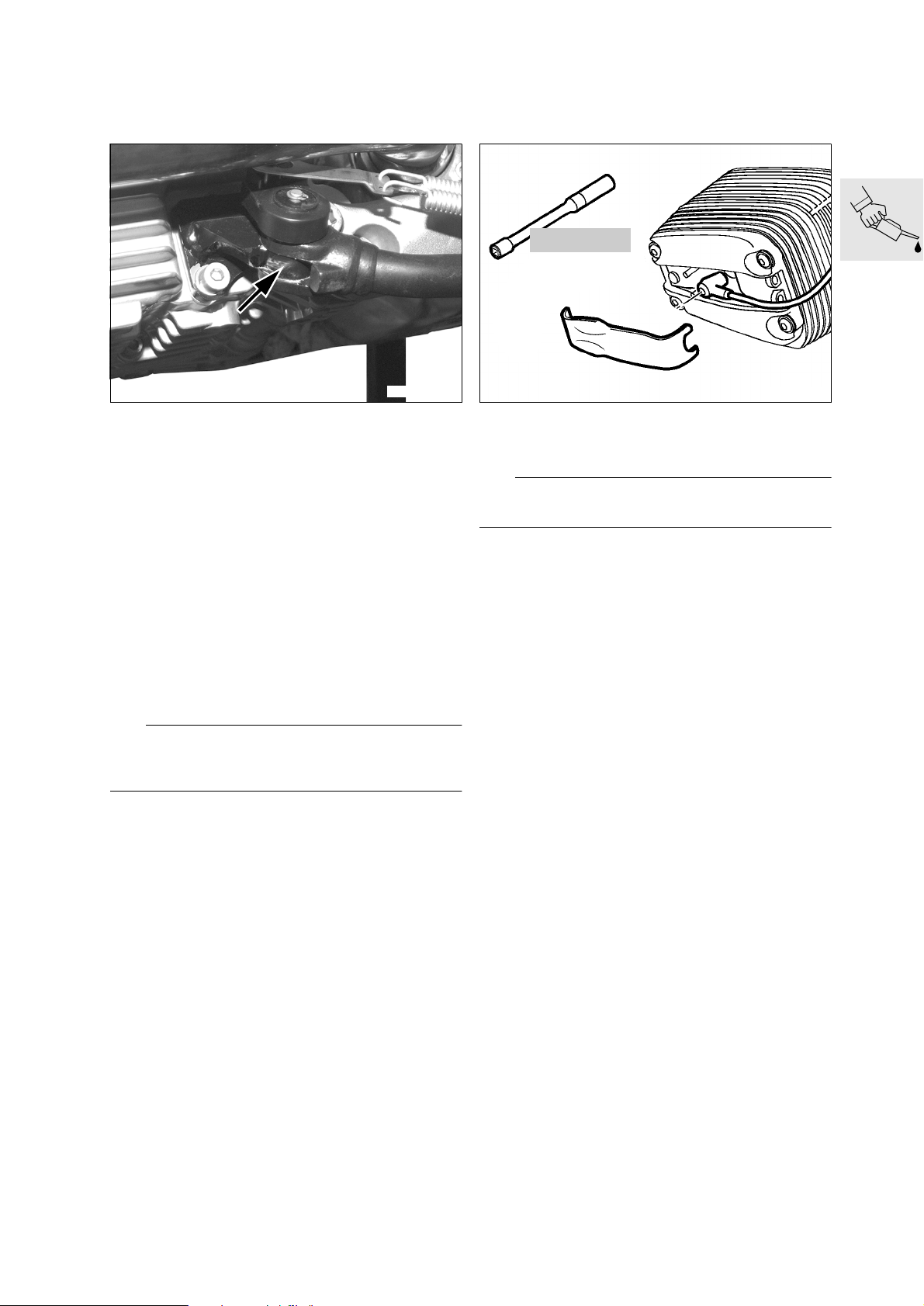
Greasing the side stand pivot
Checking/replacing spark plugs
(Inspections I, II and III)
S000220
Check free movement of side stand and grease
•
if necessary.
Grease pivot point (arrow).
•
Lubricant:
For side stand pivot.....................Shell Retinax EP2
Checking function of side stand switch
(Inspection II) check/(Inspection III) replace
12 3 510
C000060
Remove spark plugs with the spark plug wrench,
•
BMW No. 12 3 510.
e Caution:
Do not bend electrodes – risk of breakage!
Electrode gap: .......................... 0.8 mm (0.031 in)
Gap wear limit:........................... 1.0 mm (0.039 in)
(Inspections I, II, III and IV)
Place the motorcycle on the auxiliary stand,
•
BMW No. 00 1 560.
Select a gear and switch on the ignition.
•
Slowly extend the side stand and watch the neu-
•
tral indicator light.
L Note:
As the stand is extended, the neutral indicator light
must come on briefly.
X Tightening torque:
Spark plug ................................................... 20 Nm
00.35
Page 44
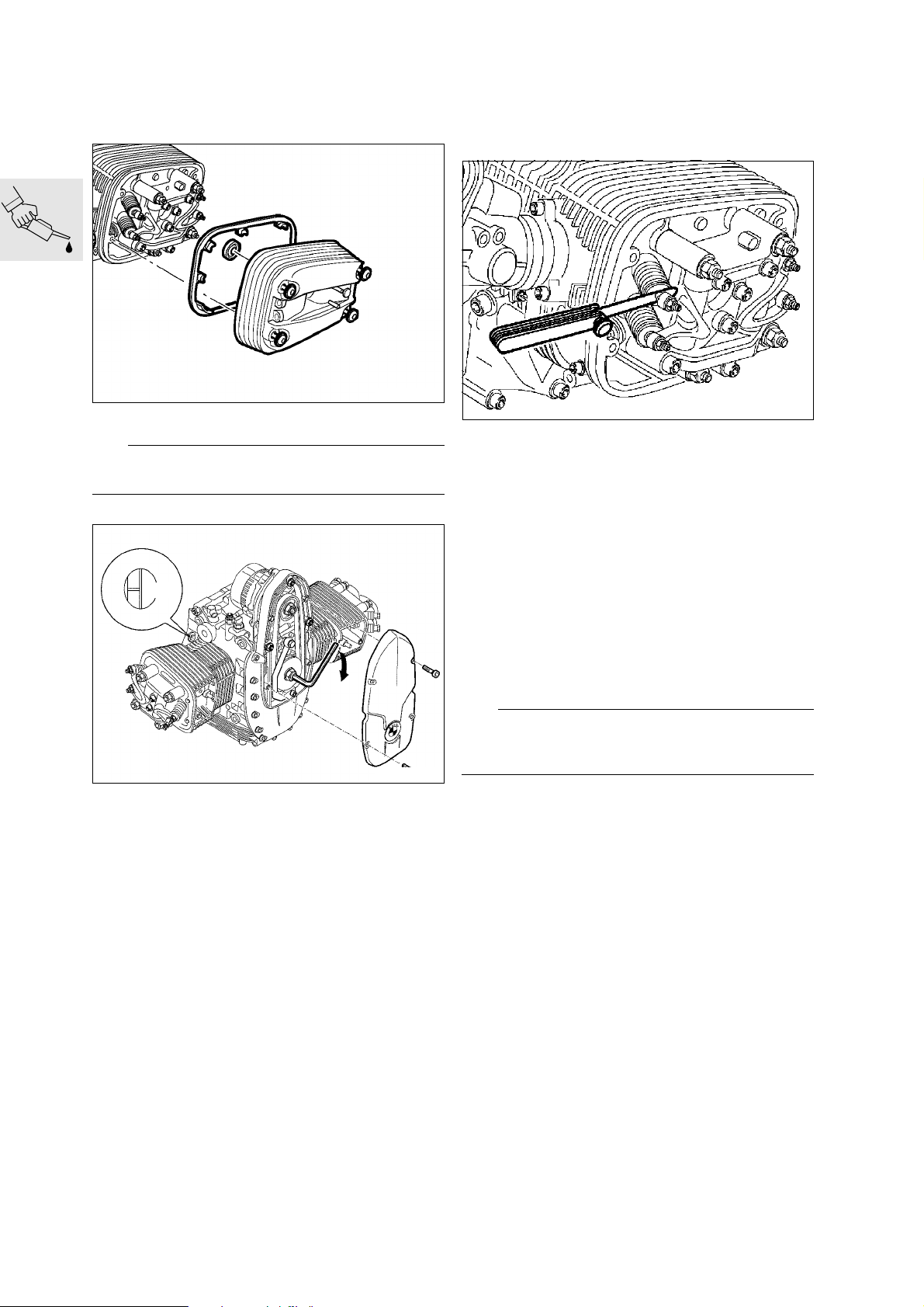
Tightening cylinder heads
(Inspection I)
Remove cylinder head cover.
•
e Caution:
Catch escaping oil.
C000210
Checking/adjusting valve clearances
(Inspections I, II and III)
RS110980
Check valve clearance with feeler gauge and, if
•
necessary, correct with adjusting screw.
Adjust valve clearances with the engine cold
(max. 35 °C/95 °F):
Inlet........................................... 0.15 mm (0.006 in)
Exhaust..................................... 0.30 mm (0.012 in)
TDC
C000070
Select a gear and turn the rear wheel, or set the
•
piston to TDC on the ignition stroke by turning
the belt pulley.
Top dead centre on ignition stroke:
The TDC mark is visible and the inlet and exhaust
•
valves in the cylinder concerned are closed.
Tighten cylinder head nuts.
•
Tightening procedure after 1 000 km (600 miles)
1. Tighten the cylinder head nuts one after the
other in diagonally opposite sequence
1.1. Slacken off one nut at a time
1.2. Tighten nut to initial torque.................... 20 Nm
1.3. Tighten nut to specified wrench angle ...... 180°
2. Release/retighten M10 screw................ 40 Nm
X Tightening torque:
Locknut.......................................................... 8 Nm
Recheck valve clearances after adjusting. Feeler
•
gauge must pull through between valve stem and
adjusting screw with slight resistance.
Assemble in the reverse of the disassembly pro-
•
cedure.
e Caution:
Make sure that gasket is correctly seated. Gaskets
and sealing faces must be free from oil or grease.
X Tightening torque:
Cylinder head cover ....................................... 9 Nm
00.36
Page 45
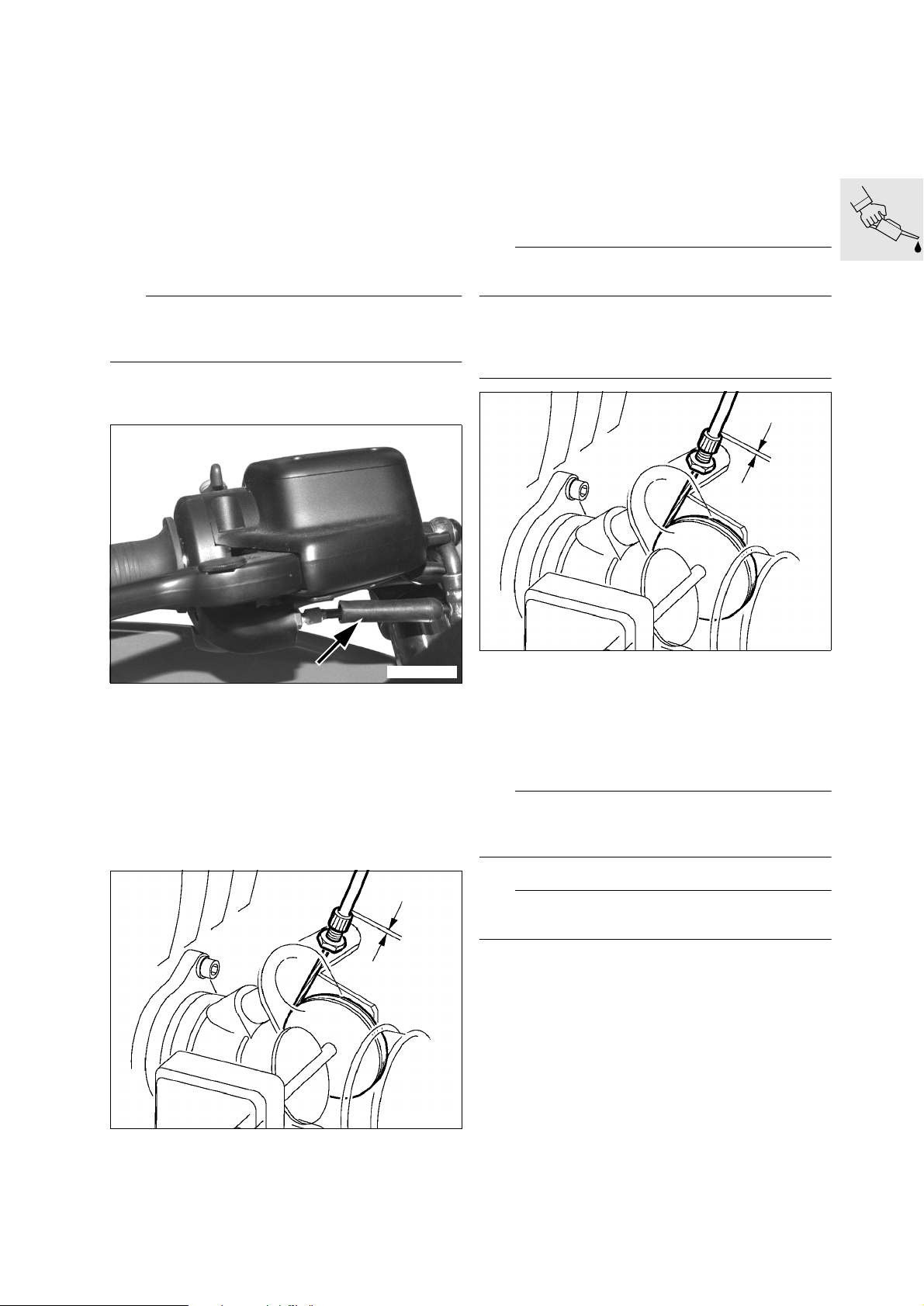
Checking throttle cable for ease of
movement, abrasion and kinks;
replacing if necessary
Checking throttle-cable play
Checking/adjusting idle speed and
throttle-valve synchronisation
Play of throttle cable: .........approx. 2 mm (0.08 in)
Connect hose of BMW Synchro to vacuum
•
adapter and connect cables to BMW MoDiTeC.
Adjust idle speed by turning the air bypass
•
screws while checking that the carburettors are
balanced.
(Inspections I, II, III and IV)
Test-drive the motorcycle until the engine is
•
warm, or allow the engine to idle for approximately 10 minutes.
e Caution:
Do not allow the engine to idle for longer than
20 minutes.
Oil temperature:...................at least 90 °C (194 °F)
Idle speed: ....................................... 1100
±50 min-1
L Note:
Make sure that both throttle valves are closed.
Caution:
Do not tamper with the sealed stop screws of the
throttle valves, as otherwise the idle-speed volume
flow will have to be reset by the manufacturer.
S000100
S000090
Push back rubber cap (arrow) on throttle and
•
choke cables.
Use the adjusting screws to adjust play of throttle
•
and choke cables.
Play of choke cable: .......... approx. 1 mm (0.04 in)
Play of throttle cable: ........ approx. 1 mm (0.04 in)
Remove right and left fairing panels.
•
S000100
Carefully turn the adjusting screw of the left throt-
•
tle valve and reduce play until the reading of the
Synchro tester changes.
Turn the adjusting screw very slightly in the op-
•
posite direction until the reading returns to its
original value.
Tighten the locknut to secure.
•
L Note:
Make sure that the reading does not change when
you tighten the locknut.
Adjust the right throttle valve in the same way.
•
L Note:
Zero play can cause the throttle valves to rattle.
Turn the adjusting screws to adjust the play of
•
the cables for the left and right throttle valves.
00.37
Page 46
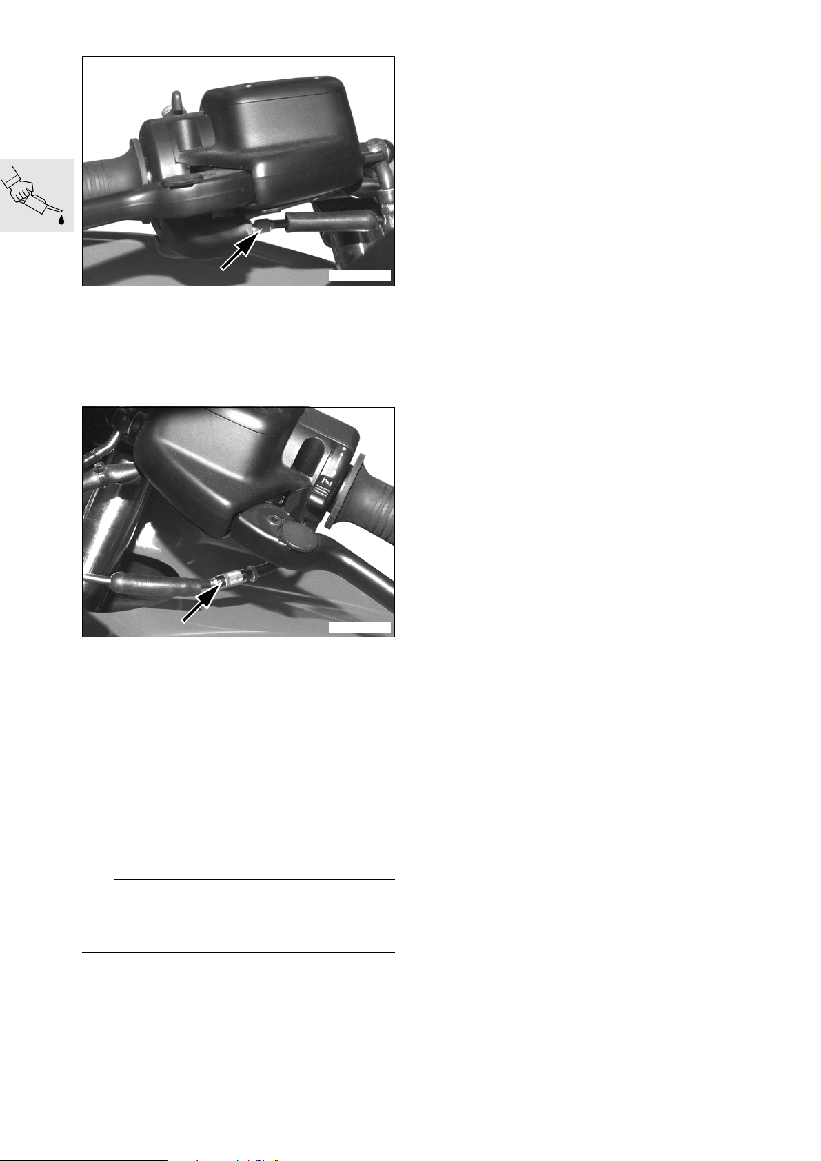
S000090
Use the adjusting screws (arrow) to adjust play of
•
the throttle cables.
Push the rubber cap into position over the ad-
•
justing screw.
Play of throttle cable: ..... approx. 0.5 mm (0.02 in)
Final inspection with road safety
and functional check
(Inspections I, II, III and IV)
Road safety check
Check wheels and tyres.
•
Check/correct tyre pressures.
•
Wait at least 10 minutes after the trial run/road
•
test before checking/correcting engine oil level.
Tyre pressures:
Solo ..................................... front 2.2 bar (31.3 psi)
.............................................rear 2.5 bar (35.6 psi)
Two up................................. front 2.5 bar (35.6 psi)
.............................................rear 2.7 bar (38.4 psi)
Two up + luggage ................ front 2.5 bar (35.6 psi)
.............................................rear 2.9 bar (41.2 psi)
Roadworthiness check
Lights
•
Telltale/warning lights
•
Horn
•
Instruments
•
Special equipment
•
Clutch
•
Gear shift
•
Steering
•
Foot brake and handbrake
•
If necessary, take the motorcycle for a test ride.
•
S000110
Use the adjusting screw (arrow) to adjust play of
•
the choke cable to zero.
Push the rubber cap into position over the ad-
•
justing screw.
Move the handlebars all the way from left to right
•
and check the settings. Make sure that engine
speed does not vary when the handlebars are
moved in this way.
Repeatedly open the throttle gradually and in-
•
crease engine speed from idle to approximately
n = 2500 min
sation. (Readings shown by Synchro tester must
increase and decrease together). If necessary,
correct by turning the adjusting screws of the
connecting cable.
-1
to check throttle-valve synchroni-
L Note:
Make sure that when the throttle grip is released
both throttle valves return to their fully closed positions.
Tighten the locknuts and recheck carburettor
•
balance.
Seal off the vacuum bores.
•
00.38
Page 47

11
11 Engine
Contents Page
Technical Data ...............................................................................................................................5
Cutaway drawing of engine
Lubricating-oil circuit ...............................................................................................................11
Cooling-oil circuit .......................................................................................................................13
Removing engine ........................................................................................................................15
Disassembling engine ..............................................................................................................17
Removing cylinder head cover ...............................................................................................18
Locking the engine at TDC .......................................................................................................19
Firing TDC .........................................................................................................................................19
Removing and installing chain
tensioner ...........................................................................................................................................20
Work instructions, timing-chain tensioner ..........................................................................................20
Removing valve gear holder ....................................................................................................21
Disassembling/assembling valve gear holder ..................................................................22
Removing cylinder head ............................................................................................................24
Disassembling, checking, repairing and reassembling cylinder head ..................25
Removing and installing valves ..........................................................................................................25
Removing valve stem seals ...............................................................................................................25
Checking valves for wear ..................................................................................................................26
Remachining valve seat .....................................................................................................................26
Checking and repairing cylinder head ...............................................................................................26
Checking valve guide for wear ...........................................................................................................26
Replacing valve guides ......................................................................................................................27
Installing valve and valve stem seal ...................................................................................................28
Removing cylinder ........................................................................................................................29
Removing and disassembling piston ...................................................................................29
Checking pistons and cylinders .............................................................................................30
Assembling pistons .....................................................................................................................30
Removing and installing conrod .............................................................................................31
Removing and installing alternator mount cover with engine installed .................32
Removing alternator mount cover .........................................................................................32
Replacing radial shaft seal in alternator mount cover ..................................................32
11.1
Page 48

Contents Page
Removing auxiliary shaft drive ................................................................................................33
Removing oil pump ......................................................................................................................34
Removing radial shaft seal from
crankshaft with engine installed .............................................................................................35
Disassembling crankcase .........................................................................................................36
Removing crankshaft, auxiliary shaft
and timing chain tensioning and slide rails .......................................................................38
Removing and installing oil intake strainers ......................................................................39
Replacing oil level sight glass .................................................................................................39
Removing and installing oil thermostat ...............................................................................39
Removing conrods .......................................................................................................................39
Checking conrods ........................................................................................................................39
Measuring crankshaft bearing play .......................................................................................40
Measuring radial bearing play ............................................................................................................40
Installing main bearings .....................................................................................................................41
Measuring axial bearing play .............................................................................................................41
Measuring big end bearing play .............................................................................................42
Assembling engine ....................................................................................................................43
Installing conrods .........................................................................................................................43
Installing crankshaft .....................................................................................................................44
Installing timing chain tensioning and slide rails .............................................................44
Installing auxiliary shaft/timing chains .................................................................................44
Assembling engine block ..........................................................................................................45
Installing radial shaft seals on crankshaft ..........................................................................48
Installing the crankshaft-end radial shaft seal ....................................................................................48
Installing the clutch-end radial shaft seal ...........................................................................................48
Installing clutch housing ............................................................................................................49
Installing oil pump .........................................................................................................................50
Installing auxiliary shaft drive ...................................................................................................51
Installing piston ..............................................................................................................................52
Installing cylinder ..........................................................................................................................53
Installing cylinder head ...............................................................................................................54
11.2
Page 49

Contents Page
Adjusting valve clearances .......................................................................................................55
Installing right cylinder head ....................................................................................................56
Adjustment specification ...................................................................................................................56
Installing left cylinder head .......................................................................................................57
Adjustment specification ...................................................................................................................57
Installing alternator mount cover ...........................................................................................59
Installing magnetic gate/belt pulley ......................................................................................59
Timing the ignition .............................................................................................................................60
Installing alternator .......................................................................................................................61
Installing engine ..........................................................................................................................62
11.3
Page 50

11.4
Page 51
11
Technical Data R 1100 S
Engine, general
Engine design Four-stroke flat twin, air-cooled with oil-
cooled exhaust ports, installed longitudinally, 4 valves per cylinder, two overhead cam-
shafts, electronic fuel injection.
Location of engine number Crankcase
Cylinder bore mm (in) 99 (3.9)
Stroke mm (in) 70.5 (2.78)
Effective displacement cc 1085
Compression ratio 11.3 : 1
Power output kW(bhp)/min
Max. torque Nm/min
-1
72(98)/7500
-1
97/5750
Permissible maximum engine speed min-18210
Idle speed min
-1
1100
±50
Direction of rotation Clockwise, looking at ignition system
Compression test pressure
good
normal
poor
bar (psi)
bar (psi)
bar (psi)
above 10 (142)
8.5...10 (121...142)
below 8.5 (121)
Intake port dia./cylinder head mm (in) 45 (1.8)
Lubrication system
Theoretical volume in circulation at 6000 min
Lubricating oil
Cooling oil
-1
l (Imp. gal/
US gal)
30 (6.6/7.9)
l (Imp. gal/
US gal)
33 (7.3/8.7)
Oil filter Full-flow type
Pressure differential needed to open
bypass valve bar (psi) 1.5 (21.3)
Oil pressure warning light comes on below bar (psi) 0.3 (4.2)
Pressure relief valve opens at bar (psi) 5.5 (78.3)
Operating pressure bar (psi) 3.5...6.0 (49.8...85.4)
Oil capacity Without filter change
With filter change
min/max
l (Imp. pints/
US quarts)
l (Imp. pints/
US quarts)
l (Imp. pints/
US quarts)
3.50 (6.16/3.70)
3.75 (6.60/3.96)
0.5 (0.88/0.53)
Permissible oil consumption
l/1000 km (miles per Imp. pint/miles per US quart) 1.0 (350/390)
Oil pump
Oil pump 2 Duocentric pumps
Housing depth Cooling oil
lube oil
Height of rotor Cooling oil
lube oil
mm (in)
mm (in)
mm (in)
mm (in)
11.02...11.05 (0.434...0.435)
10.02...10.05 (0.394...0.396)
10.95...10.98 (0.431...0.432)
9.95...9.98 (0.392...0.393)
Axial play mm (in) 0.04...0.1 (0.002...0.004)
Wear limit mm (in) 0.25 (0.010)
11.5
Page 52
Technical Data R 1100 S
Valves
Included valve angle °41
Valve clearances with engine cold (max. 35 °C/95 °F)
Inlet valve mm (in) 0.15 (0.059)
Exhaust valve mm (in) 0.30 (0.012)
Valve timing without valve clearance, 3 mm (0.12 in) valve lift
Inlet opens 5° after TDC
Inlet closes 33° after BDC
Exhaust opens 27° before BDC
Exhaust closes 5° before TDC
Tolerance ± 3°
Valve head dia.
Inlet mm (in) 34 (1.3)
Exhaust mm (in) 29 (1.1)
Stem dia.
Inlet mm (in) 4.966...4.980 (0.1955...0.1960)
Wear limit mm (in) 4.946 (0.1947)
Exhaust mm (in) 4.956...4.970 (0.1951...0.1956)
Wear limit mm (in) 4.936 (0.1943)
Valve head edge thickness
Inlet mm (in) 1.00
±0.2
(0.039
±0.008
)
Wear limit mm (in) 0.5 (0.02)
Exhaust mm (in) 1.00
±0.2
(0.039
±0.008
)
Wear limit mm (in) 0.5 (0.02)
Max. runout of valve head at valve seat
Inlet, exhaust mm (in) 0.035 (0.0014)
Valve seat ring
Valve seat angle
Inlet °45
Exhaust ° 45
Valve seat width
Inlet mm (in) 1.1
±0.15
(0.043
±0.006
)
Wear limit mm (in) 2.5 (0.10)
Exhaust mm (in) 1.4
±0.15
(0.055
±0.006
)
Wear limit mm (in) 3.0 (0.12)
Valve seat extl. dia. (dimension for machining seat)
Inlet mm (in) 33.4
Exhaust mm (in) 28.4
±0.1
±0.1
(1.315
(1.118
±0.004
±0.004
)
)
Seat ring dia. (oversize +0.2 mm/+0.008 in)
Inlet mm (in) 36.617...36.633 (1.4416...1.4422)
Exhaust mm (in) 32.134...32.150 (1.2651...1.2658)
Seat dia. in cylinder head (oversize +0.2 mm/+0.008 in)
Inlet mm (in) 36.500...36.525 (1.4370...1.4380)
Exhaust mm (in) 32.000...32.025 (1.2599...1.2608)
11.6
Page 53
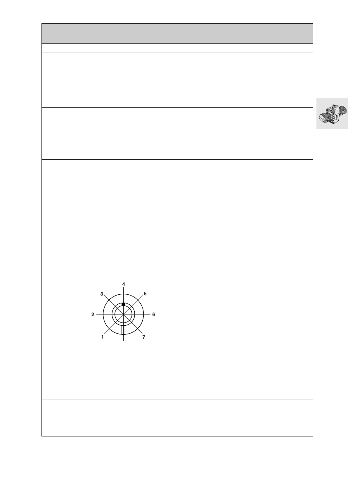
Technical Data R 1100 S
Valve guide
Valve guide Extl. dia. mm (in) 12.533...12.544 (0.4934...0.4939)
Bore in cylinder head mm (in) 12.500...12.518 (0.4921...0.4928)
Overlap mm (in) 0.015...0.044 (0.0006...0.0017)
Repair stages
Replacement valve guide Extl. dia. mm (in) 12.550...12.561 (0.4941...0.4945)
Oversize valve guide Extl. dia. mm (in) 12.733...12.744 (0.5013...0.5017)
Valve guide Intl. dia. mm (in) 5.0...5.012 (0.1969...0.1973)
Radial clearance
Inlet mm (in) 0.020...0.046 (0.0008...0.0018)
Wear limit mm (in) 0.15 (0.006)
Exhaust mm (in) 0.030...0.056 (0.0012...0.0022)
Wear limit mm (in) 0.17 (0.007)
Valve spring
Spring length, off-load mm (in) 41.1 (1.62)
Wear limit mm (in) 39.0 (1.54)
Rocker
Bore mm (in) 16.016...16.027 (0.6306...0.6310)
Rocker shaft dia. mm (in) 15.973...15.984 (0.6289...0.6293)
Radial clearance mm (in) 0.032...0.054 (0.0016...0.0021)
Wear limit mm (in) 0.1 (0.004)
Axial play min. mm (in) 0.05 (0.002)
max. mm (in) 0.40 (0.016)
Camshaft
Opening angle, inlet/exhaust cams 300°
Cam spread, inlet/exhaust 109°/106°
Marking Mark in
position 4
Inlet valve lift mm (in) 9.7 (0.38) (valve clearance = 0)
Exhaust valve lift mm (in) 9.3 (0.36) (valve clearance = 0)
Camshaft bearing bore mm (in) 21.02...21.04 (0.8276...0.8284)
Camshaft dia. mm (in) 20.97...21.00 (0.8256...0.8268)
Radial clearance mm (in) 0.02...0.07 (0.0008...0.0028)
Wear limit mm (in) 0.15 (0.006)
Width of guide bearing mm (in) 15.92...15.95 (0.6268...0.6280)
Width of camshaft bearing mm (in) 16.0...16.05 (0.6299...0.6319)
Axial play mm (in) 0.08...0.13 (0.0031...0.0051)
Wear limit mm (in) 0.25 (0.010)
11.7
Page 54
Technical Data R 1100 S
Bucket-type tappet
Extl. dia. mm (in) 23.947...23.960 (0.9428...0.9433)
Bore in cylinder head mm (in) 24.000...24.021 (0.9449...0.9457)
Radial clearance mm (in) 0.040...0.074 (0.0016...0.0029)
Wear limit mm (in) 0.18 (0.007)
Auxiliary shaft
Bore in crankcase
front/back mm (in) 25.020...25.041 (0.9851...0.9859)
Auxiliary shaft dia.
front/back mm (in) 24.959...24.980 (0.9827...0.9835)
Radial clearance mm (in) 0.040...0.082 (0.0016...0.0032)
Wear limit mm (in) 0.17 (0.007)
Crankshaft
Marking of main bearing and crankpin on front crank
web
no paint mark Grinding stage 0
paint mark Grinding stage 1 (-0.25 mm/-0.010 in)
Grinding stage 0
(grinding stage 1 = —0.25 mm/–0.01 in)
Guide bearing bore mm (in) 64.949...64.969 (2.5571...2.5579)
Guide bearing dia. mm (in) Green: 59.964...60.003 (2.3609...2.3624)
mm (in) Yellow: 59.974...60.013 (2.3612...2.3628)
Main bearing journal dia. mm (in) Green: 59.939...59.948 (2.3598...2.3602)
mm (in) Yellow: 59.949...59.958 (2.3602...2.3606)
Radial clearance mm (in) 0.016...0.064 (0.0006...0.0025)
Wear limit mm (in) 0.1 (0.004)
Main bearing bore mm (in) 60.000...60.019 (2.3622...2.3629)
Main bearing dia. mm (in) Green: 54.998...55.039 (2.1653...2.1669)
mm (in) Yellow: 55.008...55.049 (2.1657...2.1673)
Main bearing journal dia. mm (in) Green: 54.971...54.980 (2.1643...2.1646)
mm (in) Yellow: 54.981...54.990 (2.1646...2.1650)
Radial clearance mm (in) 0.018...0.068 (0.0007...0.0028)
Wear limit mm (in) 0.13 (0.005)
Width of guide bearing mm (in) 24.890...24.940 (0.9799...0.9819)
Width of main bearing journal mm (in) 25.020...25.053 (0.9851...0.9864)
Axial play mm (in) 0.080...0.163 (0.0031...0.0064)
Wear limit mm (in) 0.2 (0.008)
Grinding stage 0 (grinding stage 1 = –0.25 mm/–0.01 in)
Crankpin dia. mm (in) 47.975...47.991 (1.8888...1.8894)
Width of crankpin mm (in) 22.065...22.195 (0.8687...0.8738)
11.8
Page 55
Technical Data R 1100 S
Connecting rod
Big-end bore mm (in) 51.000...51.013 (2.0079...2.0084)
Big end bearing dia. mm (in) 48.016...48.050 (1.8904...1.8918)
Radial clearance mm (in) 0.025...0.075 (0.010...0.0030)
Wear limit mm (in) 0.13 (0.005)
Width of big end bearing eye mm (in) 21.883...21.935 (0.8616...0.8636)
Conrod end float mm (in) 0.130...0.312 (0.0051...0.0123)
Wear limit mm (in) 0.5 (0.02)
Small-end bore mm (in) 22.015...22.025 (0.8664 ... 0.8671)
Radial clearance mm (in) 0.015...0.030 (0.0006...0.0012)
Wear limit mm (in) 0.06 (0.002)
Distance between centers mm (in) 125 (4.92)
Max. deviation from parallel of conrod bores
at distance of 150 mm (5.90 in) mm (in) 0.07 (0.003)
Cylinders
Bore (20 mm/0.79 in from top edge)
A mm (in) 98.992...99.000 (3.8974...3.8977)
Wear limit mm (in) 99.050 (3.8997)
B mm (in) 99.000...99.008 (3.8977...3.8980)
Wear limit mm (in) 99.058 (3.9000)
Total wear clearance of piston and cylinder mm (in) 0.12 (0.005)
Permitted out-of-round of cylinder bore
20 mm (0.79 in) from the top edge mm (in) 0.03 (0.001)
100 mm (3.94 in) from the top edge mm (in) 0.04 (0.002)
Pistons
Piston dia. (Measuring plane A — see Checking pistons and
cylinders)
A mm (in) 98.971...98.983 (3.8966...3.8970)
Wear limit mm (in) 98.895 (3.8936)
B mm (in) 98.983...98.995 (3.8970...3.8975)
Wear limit mm (in) 98.905 (3.8940)
AB mm (in) 98.979...98.987 (3.8969...3.8972)
Wear limit mm (in) 98.900 (3.8938)
Installed clearance mm (in) 0.005...0.029 (0.0002...0.0011)
Total wear clearance of piston and cylinder mm (in) 0.12 (0.005)
Piston pin bore mm (in) 22.005...22.011 (0.8664...0.8666)
Weight classes + and —
Weight difference in one class grammes
(oz.) 10 (0.353) (complete with pins and rings)
Direction of installation Arrow on piston crown pointing to exhaust side
Production locating point towards exhaust side
(see Installing piston)
11.9
Page 56
Technical Data R 1100 S
Piston rings
1st groove Piston ring
asymmetric, convex oval
Thickness mm (in) 1.170...1.190 (0.0461...0.0469)
Wear limit mm (in) 1.1 (0.04)
End gap mm (in) 0.1...0.3 (0.004...0.012)
Wear limit mm (in) 0.8 (0.03)
Side clearance mm (in) 0.030...0.070 (0.0012...0.0027)
Wear limit mm (in) 0.15 (0.006)
2nd groove Micro-taper compression ring
Thickness mm (in) 1.175...1.190 (0.0463 ...0.0469)
Wear limit mm (in) 1.1 (0.04)
End gap mm (in) 0.1...0.3 (0.004...0.012)
Wear limit mm (in) 0.8 (0.03)
Side clearance mm (in) 0.030...0.065 (0.0012...0.0026)
Wear limit mm (in) 0.15 (0.006)
3rd groove 3 - S ring
Height mm (in) 2.0 (0.078)
Wear limit mm (in) 1.9 (0.075)
End gap mm (in) 0.30...0.60 (0.012...0.024)
Wear limit mm (in) 1.20 (0.047)
Side clearance mm (in) 0.020...0.055 (0.0008...0.0022)
Wear limit mm (in) 0.15 (0.006)
Installed direction of piston rings “Top” marking uppermost
Piston pin
Piston pin dia. mm (in) 21.995...22.000 (0.8664...0.8662)
Wear limit mm (in) 21.960 (0.8646)
Bore in piston mm (in) 22.005...22.011 (0.8664...0.8666)
Radial clearance in piston mm (in) 0.005...0.016 (0.0002...0.0006)
Wear limit mm (in) 0.070 (0.0028)
11.10
Page 57
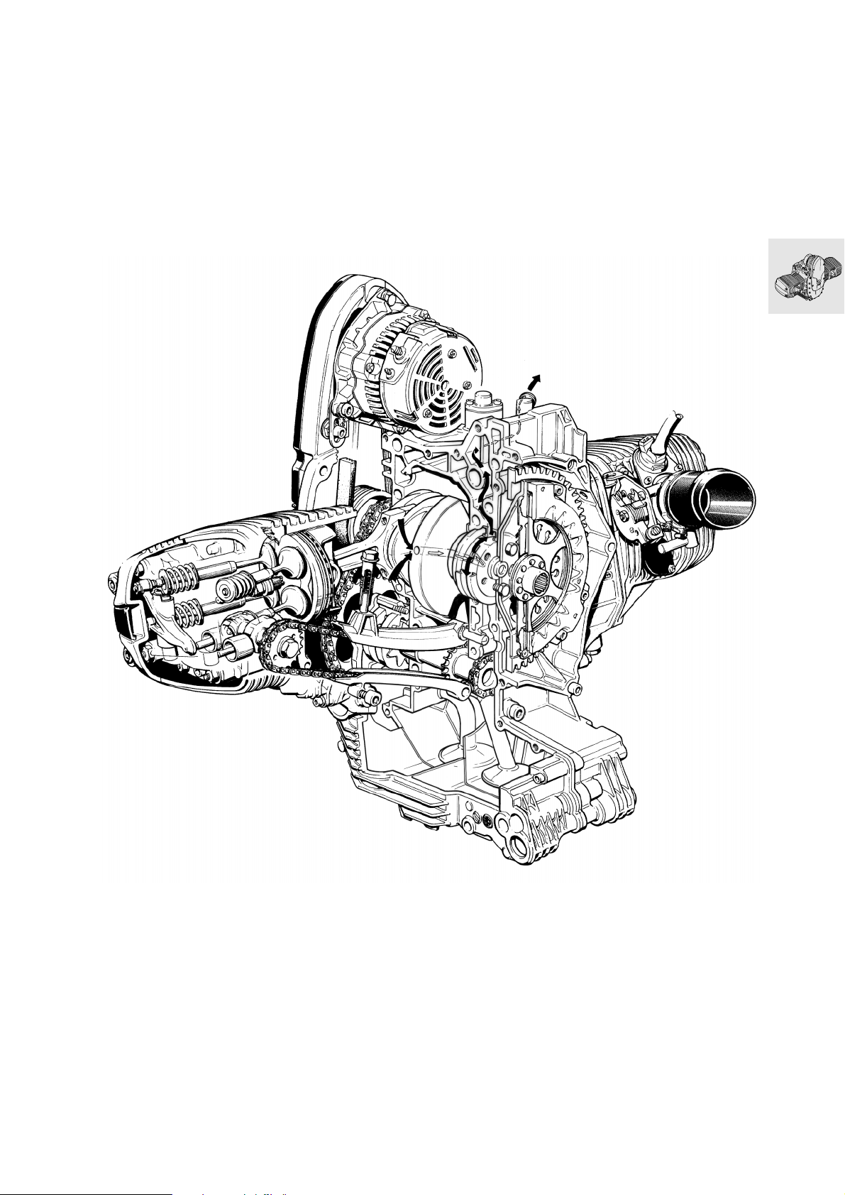
Cutaway drawing of engine
11.11
Page 58
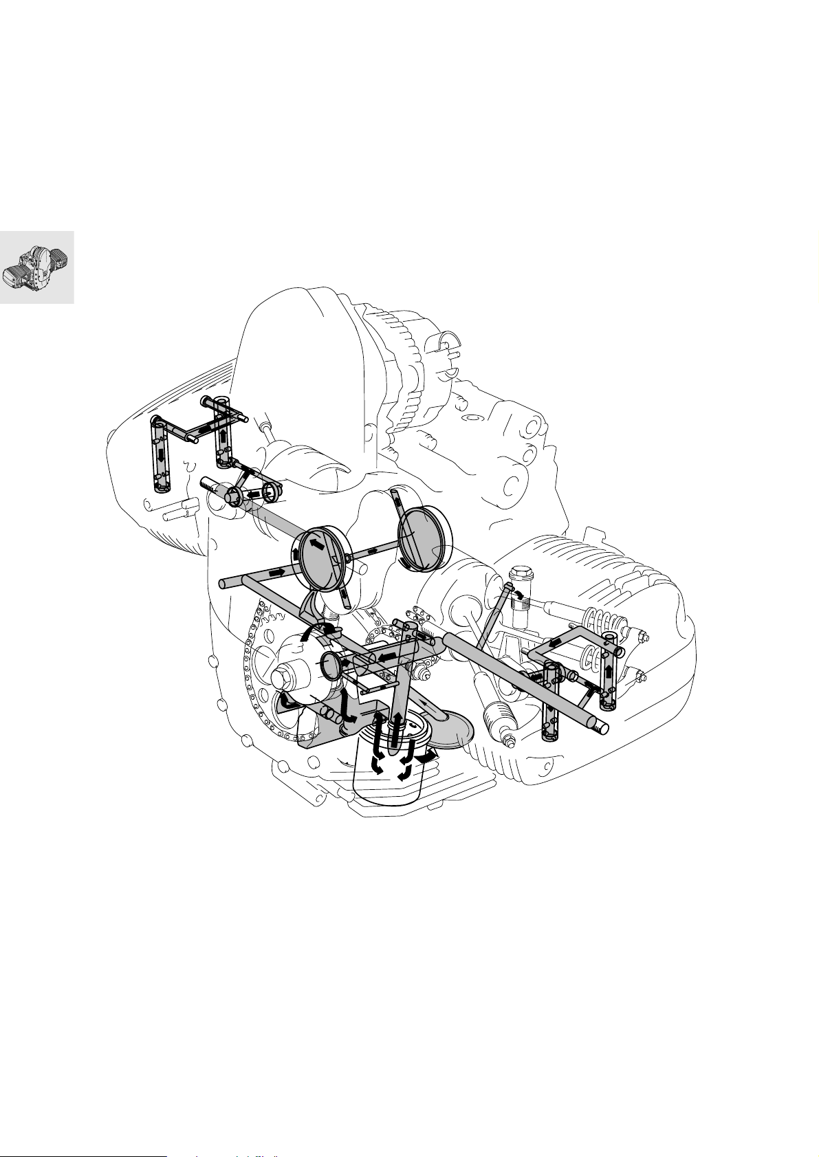
Lubricating-oil circuit
11.12
Page 59
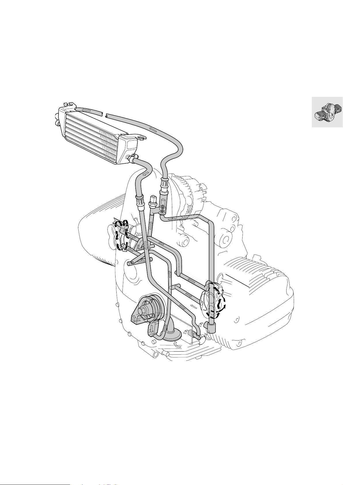
Cooling-oil circuit
11.13
Page 60

11.14
Page 61
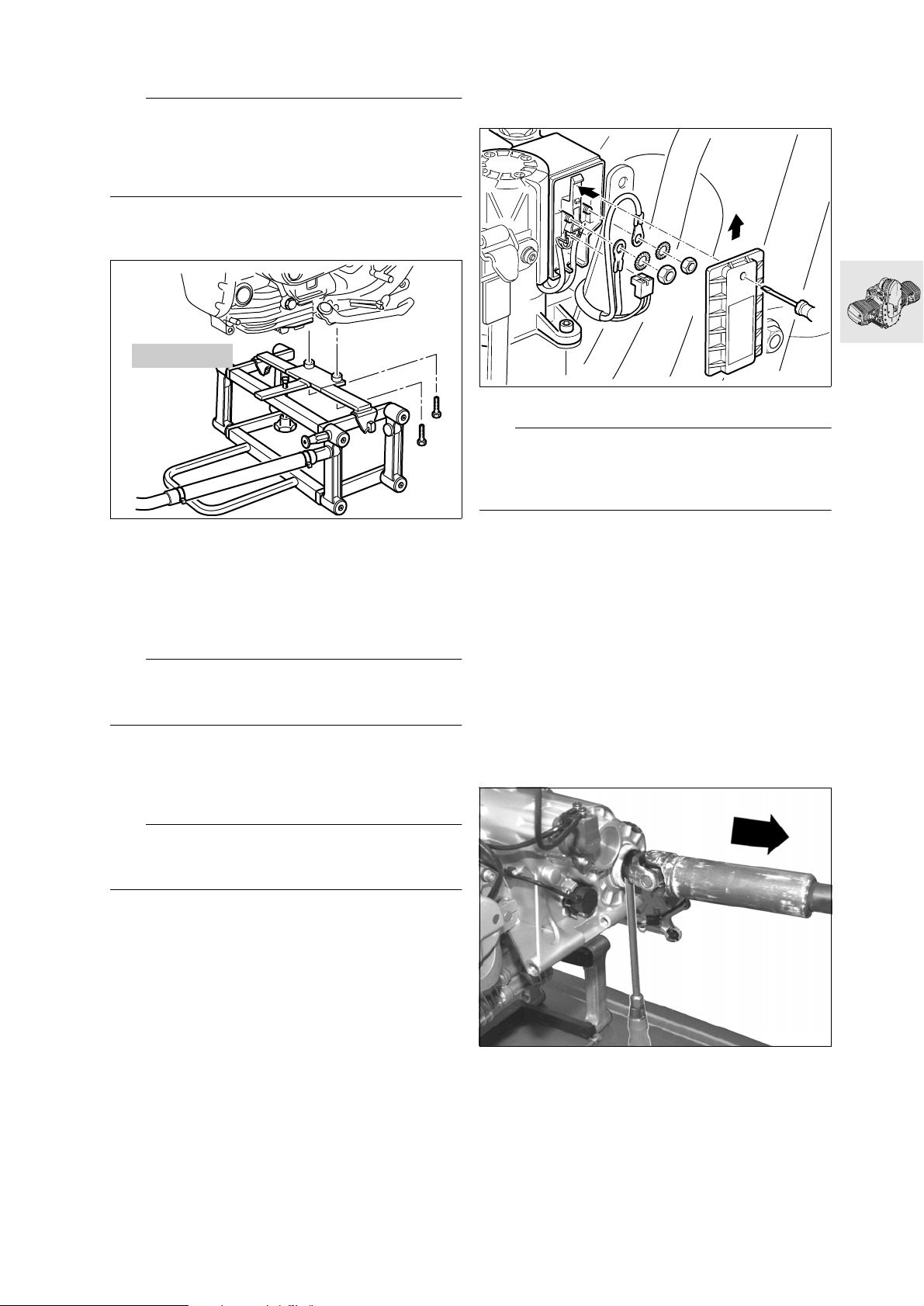
Removing engine
L Note:
Auxiliary shaft, timing chains, chain tensioner/guide
rails and crankshaft can only be disassembled after
the engine has been removed. All other components
can be disassembled with the engine installed.
Drain engine oil.
•
[ABS] Fully drain the brake system.
•
00 1 520
S110010
Secure stand, BMW No. 00 1 520, to motorcy-
•
cle.
Remove seat.
•
Remove left side trim.
•
Remove right side trim.
•
Remove the intake air pipe.
•
Disengage the fuel tank.
•
e Caution:
Fuel is flammable and a hazard to health. Observe
relevant safety regulations.
Seal the fuel feed and return lines with hose
•
clips, BMW No. 13 3 010, and disconnect.
Pull the plug connector off the fuel pump unit.
•
Lift off fuel tank.
•
Remove the battery.
•
[ABS] Disconnect plug from pressure modulator.
•
[ABS] Disconnect brake lines from pressure
•
modulator.
S340071
[ABS] Remove cover and disconnect cables.
•
e Caution:
Comply exactly with the instructions in the Repair
Manual.
aGroup 34/Removing ABS unit
[ABS] Remove the pressure modulator.
•
Remove the rear side panel on the right.
•
Disconnect plug for rear wiring harness.
•
[ABS] Disconnect sensor plug.
•
Disconnect plug for brake-light switch.
•
Disconnect plug for inductive sensor, speedom-
•
eter.
Release right footrest plate.
•
[ABS] Remove rear brake lines.
•
Disconnect gearshift linkage at ball head.
•
Disconnect plug for lambda sensor.
•
Disconnect rear silencer from front silencer.
•
Remove lambda sensor.
•
Disconnect main frame and use workshop crane,
•
BMWNo.465640, to lift main frame.
e Caution:
Disconnect negative terminal first, then positive terminal.
Remove the rear brake caliper.
•
[ABS] Remove rear sensor.
•
Remove inductive sensor from rear wheel drive.
•
The motorcycle is heavy at the rear; use a ratch-
•
et-lock belt to pull the motorcycle down at the
nose on the lifting platform.
Remove rear wheel.
•
Remove retainer from rubber bellows of swinging
•
arm at rear wheel drive.
Swinging-arm bearing studs are secured with
•
Loctite: heat to max. 120 °C (248 °F) to release.
Slacken nut of swinging-arm floating bearing.
•
Loosen the floating bearing stud bolt.
•
Loosen the fixed bearing stud bolt.
•
Disengage reaction link from rear wheel drive.
•
Remove fixed and floating bearing stud bolts and
•
remove rear wheel drive.
Remove screw at top of suspension strut.
•
S330170
Use a screwdriver to press out the universal
•
shaft.
Disconnect plug for air-temperature sensor from
•
air filter box.
Release hose clips at the air intake necks.
•
Push the air intake necks into the air filter box.
•
11.15
Page 62
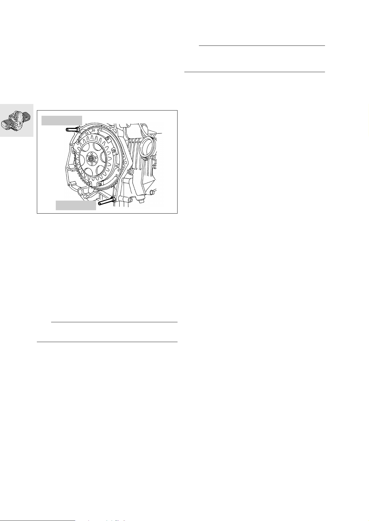
Use pliers, BMW No. 17 5 500, to release hose
•
clip securing breather hose to air filter box.
Remove air filter box.
•
Remove starter-motor cover.
•
Remove the starter motor.
•
Disconnect plug for gearshift switch.
•
Release the clutch slave cylinder and pull it out
•
of the housing.
Release the battery carrier can pull it up and out
•
of the rubber mount.
Remove the fuel distributor with injectors.
•
Remove the gearbox securing screws.
•
23 1 820
Remove front silencer.
•
Use a strap with ratchet latch to secure bottom
•
fork bridge to top fork bridge.
L Note:
This precaution is necessary, as otherwise the fork
would fall apart.
Use workshop crane to raise the entire front end
•
of the motorcycle.
Installation is the reverse of the removal proce-
•
dure.
23 1 820
Always use guide pins, BMW No. 23 1 820, when
•
removing or installing the gearbox.
Remove the windshield.
•
Secure the top fork bridge to workshop crane,
•
BMWNo.465640.
Disconnect suspension strut from leading link.
•
Heat the ball joint mount at the leading link to
•
max. 120 °C (248 °F) and disengage.
Release throttle flap stub pipes.
•
Remove the leading link caps.
•
Remove the left screw cap.
•
Remove the circlip at the right and the safety
•
cap.
Remove the screw at the right and pull the shaft
•
out to the left.
RS230010
e Caution:
Do not scratch the surface of the leading link.
Pull telescopic fork forwards.
•
Remove the leading link.
•
Disconnect oil cooler return line from oil cooler.
•
Remove screws securing oil cooler return line to
•
fairing bracket.
Disconnect oil cooler supply line from engine.
•
Disconnect plug for oil-temperature sensor.
•
Disconnect plug for oil-pressure switch.
•
Disconnect cables from three-phase generator.
•
Disconnect cables from cable guide/engine.
•
Disconnect plug from Hall sensor.
•
Remove bolts from front frame.
•
Pull off spark plug caps with special puller,
•
BMW No. 12 3 520.
Disconnect Motronic control unit.
•
Remove battery carrier.
•
Disconnect ground cable from engine.
•
Disconnect plug for side stand.
•
Remove side stand with retaining plate.
•
Remove manifolds.
•
11.16
Page 63
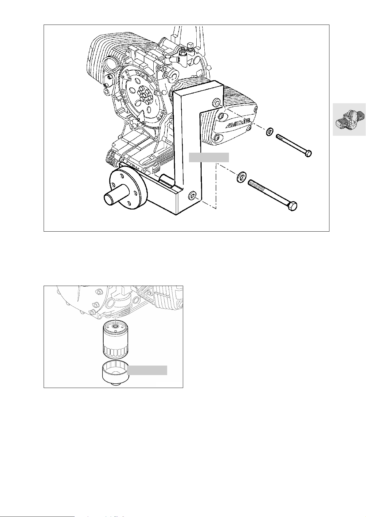
Disassembling engine
Secure engine mount, BMW No. 11 0 630, to the
•
engine block.
Transfer engine to assembly frame.
•
00 0 630
RS110010
11 4 650
Drain engine oil.
•
Remove the oil filter, using oil filter wrench,
•
BMW No. 11 4 650.
RS110950
11.17
Page 64
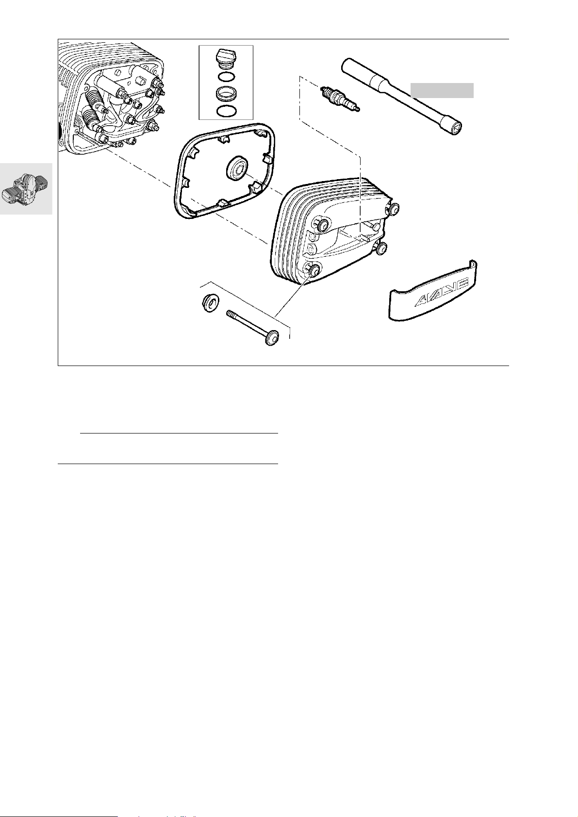
12 3 510
RS110020
Removing cylinder head cover
Remove spark plugs with the spark plug wrench,
•
BMW No. 12 3 510.
Remove cylinder head cover.
•
e Caution:
Catch escaping oil.
11.18
Page 65
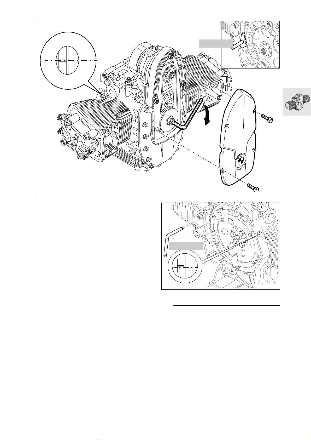
TDC
11 5 640
RS110030
Locking the engine at TDC
Remove front cover.
•
Turn the belt pulley to bring the piston to firing
•
TDC.
Firing TDC
1. TDC mark is visible, and
2. The inlet and exhaust valves of the cylinder in
question are closed.
Lock the clutch housing with special tool,
•
BMW No. 11 5 640.
11 2 650
TDC
RS110461
L Note:
The engine can be locked at TDC by inserting locating pin, BMW No. 11 2 650, through the hole in the
clutch housing and the engine block.
11.19
Page 66
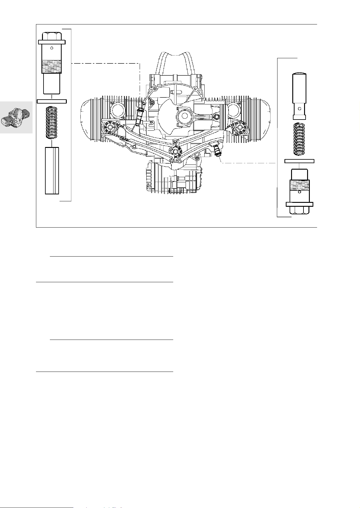
Removing and installing chain tensioner
e Caution:
Do not mix up the chain tensioner pistons. When installing, fit a new seal.
Work instructions, timing-chain tensioner
Removing:
Remove timing chain tensioner, then remove
•
camshaft sprocket from camshaft.
Installing:
First install camshaft sprocket, then timing chain
•
tensioner.
e Caution:
Failure to observe this sequence can cause the
chain tensioner piston on the left to drop into the
timing-chain chamber.
X Tightening torque:
Chain tensioner............................................ 32 Nm
RS110060
11.20
Page 67
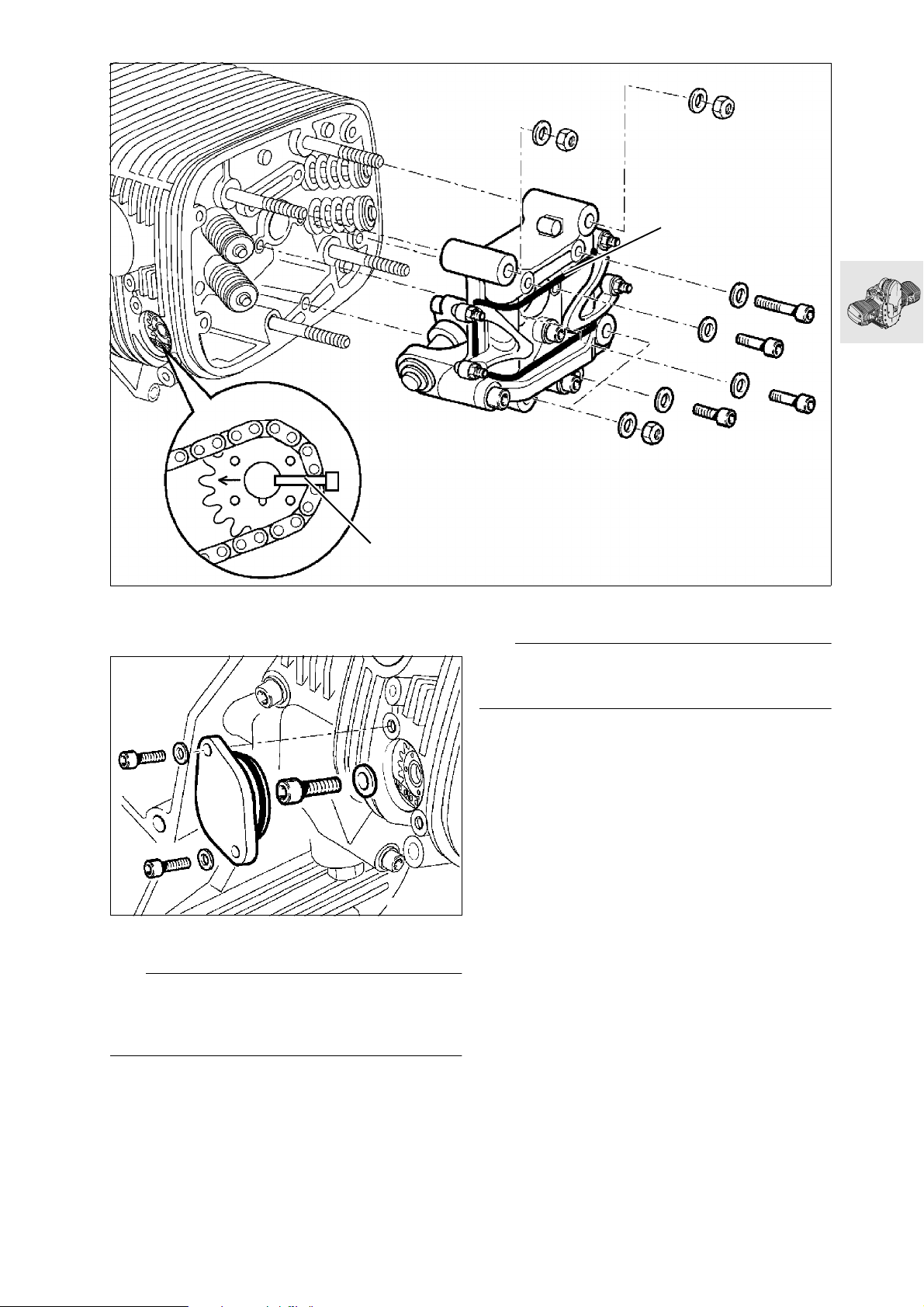
2
M6 x 60
M6 x 30
Removing valve gear holder
M6 x 30
M6 x 30
1
S110110
Remove valve gear holder.
•
Secure rockers with a rubber band (2).
•
L Note:
If no work is carried out on the valve gear holder, remove it together with the cylinder head.
RS110051
Remove camshaft sprocket cover.
•
Remove/pull off camshaft sprocket.
•
L Note:
If the camshaft sprocket (1) is not removed after
loosening, it must be held firmly and prevented from
falling into the engine block (e.g. with a cable strap).
11.21
Page 68
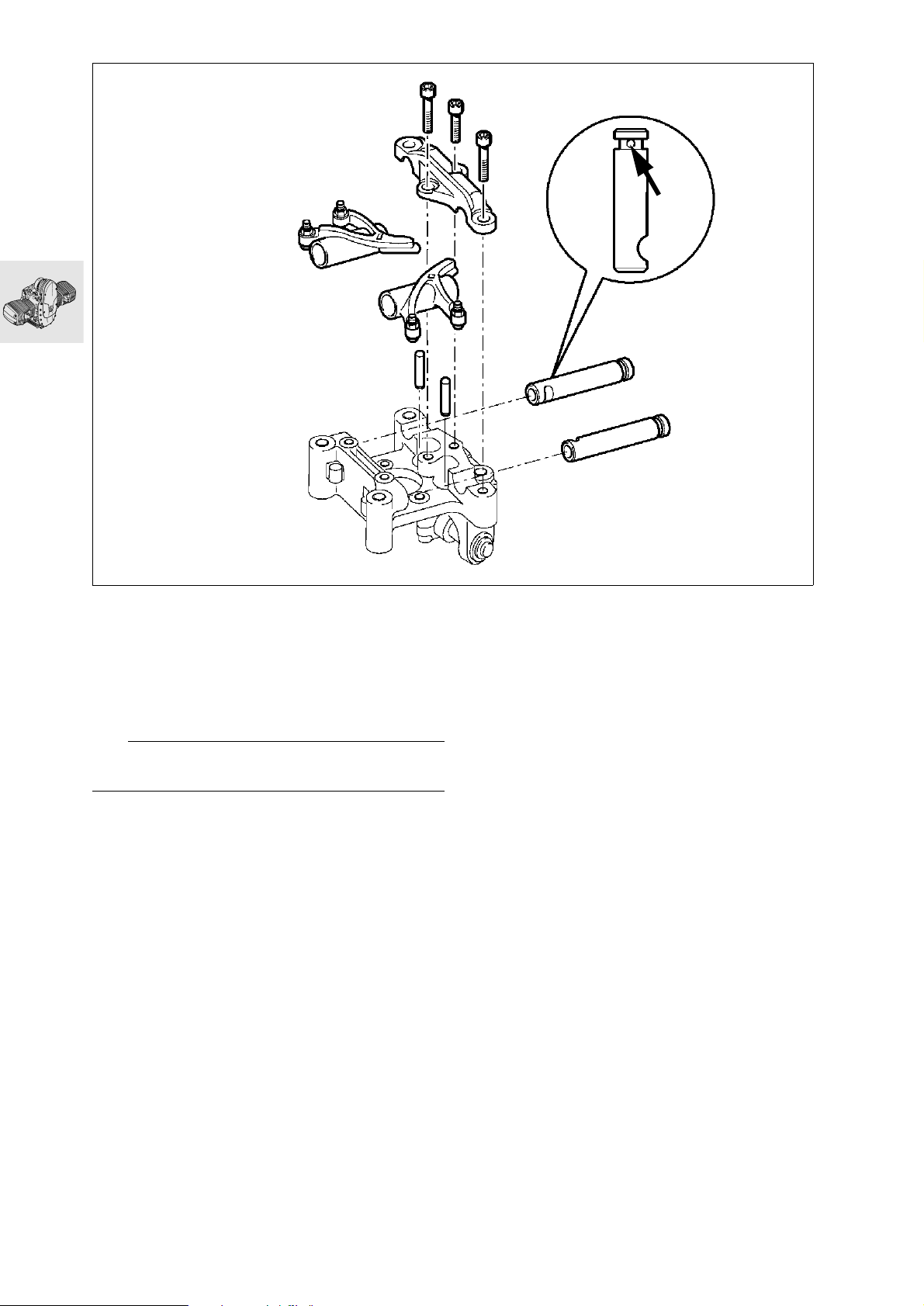
M8 x 40
M8 x 30
M8 x 40
RS110080
Disassembling/assembling valve gear holder
Remove bearing cap.
•
Insert a suitable pin into the bore (arrow) of the
•
rocker shaft, and turn the shaft back and forth to
remove it from its bearing.
Remove pushrods.
•
e Caution:
Do not mix up the rocker shafts and pushrods.
11.22
Page 69
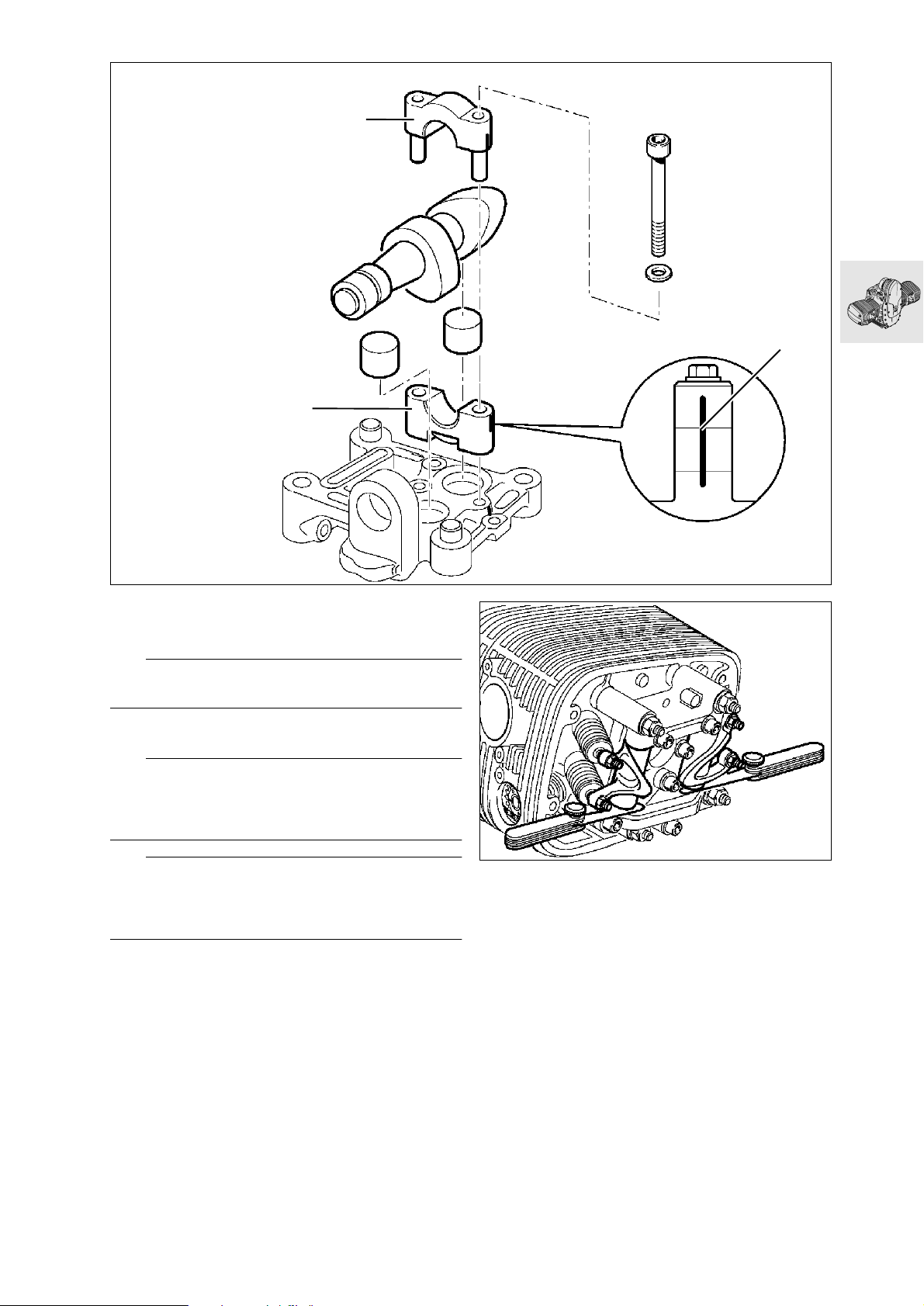
1
M8 x 65
3
2
Remove camshaft bearing cap (1).
•
Remove camshaft and bearing (2).
•
Remove bucket-type tappets.
•
e Caution:
Do not mix up the bucket-type tappets.
Assembly is the reverse of the disassembly pro-
•
cedure.
e Caution:
Note direction of installation (3) for camshaft bearing
cap. Rocker-shaft recess must be aligned with the
bores.
L Note:
Locate pushrods in ball cups of rockers and hold the
rockers together with a rubber band to secure the
pushrods in position.
X Tightening torque:
M 8 screw, rocker shaft bearing cap ............ 15 Nm
M 8 screw for camshaft bearing cap ........... 15 Nm
RS110090
RS110100
Adjust the holder for minimum end float.
•
End float of rockers:
min............................................ 0.05 mm (0.002 in)
max. ......................................... 0.40 mm (0.016 in)
11.23
Page 70
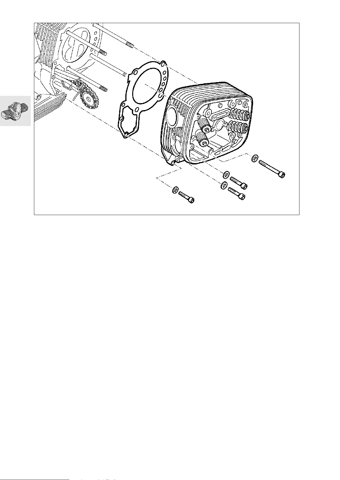
M6 x 30
M10 x 70
Removing cylinder head
M6 x 30
M6 x 30
RS110110
11.24
Page 71
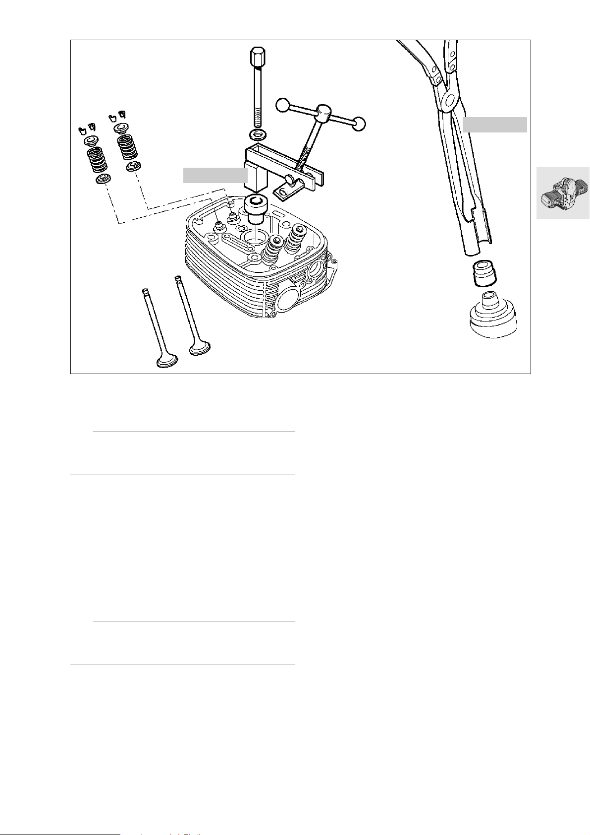
11 5 690
Disassembling, checking, repairing
and reassembling cylinder head
11 1 250
RS110130
Removing and installing valves
e Caution:
Do not scratch sealing face on cylinder head. Place
the head on a clean, non-scratching surface.
Mount valve spring compressor,
•
BMW No. 11 5 690, on cylinder head.
Compress the valve springs.
•
Gently tap valve head to release collets from
•
spring retainer.
Remove valve collet sections.
•
Relieve tension on valve springs.
•
Remove top and bottom spring retainers, valve
•
springs and valves.
Removing valve stem seals
Pull off valve stem seal with pliers,
•
BMW No. 11 1 250.
L Note:
If a valve is removed, the valve stem seal must be replaced.
11.25
Page 72
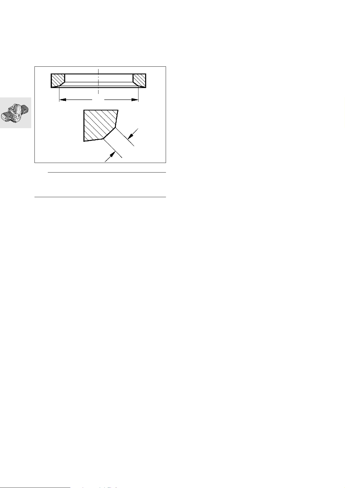
Checking valves for wear
Clean combustion residue from valves.
•
Check valve dimensions.
•
a ............................................see Technical Data
Remachining valve seat
D
B
RS110890
e Caution:
Width (B) and diameter (D) must always be maintained if valve seat is machined.
a ............................................see Technical Data
Checking and repairing cylinder head
Remove combustion residues from combustion
•
chamber.
Check sealing face for damage/distortion, and
•
skim flat if necessary.
Skimming sealing
face: ........... max. 0.2 mm (0.008 in) metal removal
Checking valve guide for wear
Check valve guide bore.
•
a ............................................see Technical Data
11.26
Page 73
Replacing valve guides
Heat cylinder head slowly and uniformly to
•
200 °C (392 °F) in a suitable oven.
e Caution:
Wear protective gloves when handling heated parts.
Drive out valve guides with 5 mm (0.20 in) dia.
•
drift, BMW No. 11 5 674, from the combustion
chamber side.
Allow cylinder head to cool down to room tem-
•
perature (app. 20 °C/68 °F).
Examine valve guide bore for:
•
–wear,
– widening taper and
– correct dimensions in H7 tolerance range
(12.500...12.518 mm/0.4921...0.4928 in).
L Note:
Valve guides are press-fitted in the cylinder head
with an interference fit of 0.015...0.044 mm
(0.0006...0.0017 in).
If valve guide bore is undamaged and dimensions are within correct 12.5 H7 tolerance range:
Use original 12.5 U6 (12.533...12.544 mm/
•
0.4934...0.4939 in) valve guide.
Measure valve guides with micrometer.
•
Slowly heat cylinder head to 200 °C (392 °F) in a
•
suitable oven.
Immerse valve guide in liquid grinding paste.
•
Chill valve guide with dry ice.
•
e Caution:
Immediately before pressing in, the temperature
must be –40 °C (–40 °F).
Place heated cylinder head flat on workbench or
•
a similar surface.
Mount the chilled valve guide on Ø 5 mm (0.20 in)
•
drift, BMW No. 11 5 673.
Drive valve guides into cylinder head with no de-
•
lay.
Allow cylinder head to cool down to room tem-
•
perature, app. 20 °C (68 °F).
Inspect bores of valve guides.
•
L Note:
Valve guides for repair purposes are produced with
an internal diameter of 5.01 mm (0.1972 in) H7.
In most cases, the bore is within the 5.00 mm
(0.1969 in) H7 tolerance range after pressing in.
If the bore is too narrow, ream it out to size.
If valve guide bore is undamaged but slightly
larger than the 12.5 H7 tolerance range:
Use replacement valve guide
•
12.550...12.561 mm (0.4941...0.4945 in).
If valve guide bore is damaged or not to correct
dimensions in 12.5 H7 tolerance range:
Use an oversize 12.7 U6 (12.733...12.744 mm/
•
0.5013...0.5017 in) valve guide.
Repair method 1 – ream out the bore
(if bore is damaged or not to correct dimensions)
Determine actual diameter of valve guide using
•
micrometer.
Ream bore with Ø12.7 H7 mm
•
(12.700...12.718 mm/0.5000...0.5007 in) reamer.
Repair method 2 – turn the valve guide on a lathe
(bore must not be damaged)
Measure bore with internal measuring tool.
•
Calculate the nominal diameter of the valve
•
guide:
Required diameter of valve guide = bore dia. + interference-fit value (0.015...0.044 mm/
0.0006...0.0017 in).
Use an oversize 12.7 U6 (12.733...12.744 mm/
•
0.5013...0.5017 in) valve guide.
Machine oversize valve guide to required diame-
•
ter.
11.27
Page 74
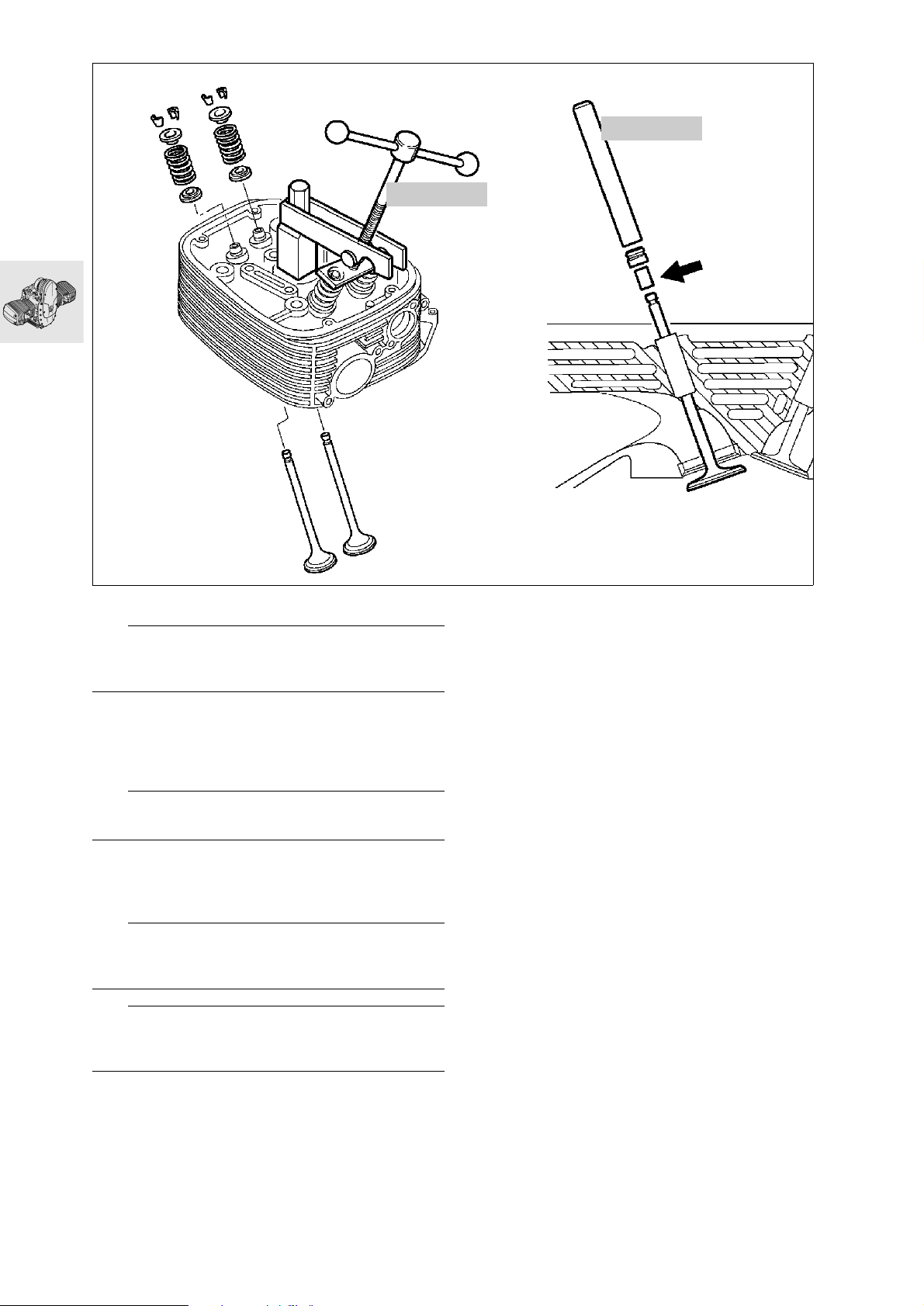
11 5 690
11 5 602
RS110160
Installing valve and valve stem seal
L Note:
If a valve was removed, the valve stem seal must be
replaced.
Oil the stem before installing the valve.
•
Shrink a short length of tube (arrow) on to the end
•
of the valve stem.
Install the valve stem seal with a 5 mm (0.20 in)
•
dia. drift, BMW No. 11 5 602.
e Caution:
Remove the shrink-fit tube.
Install lower spring retainer, valve spring and up-
•
per spring retainer.
Compress the valve springs with the valve spring
•
compressor, BMW No. 11 5 690.
L Note:
Apply grease to valve collets (to facilitate installation)
and install.
e Caution:
Make sure that valve collets are correctly seated in
the valve stem grooves.
Relieve tension on valve springs.
•
Check valves for leakage (blow-by).
•
11.28
Page 75
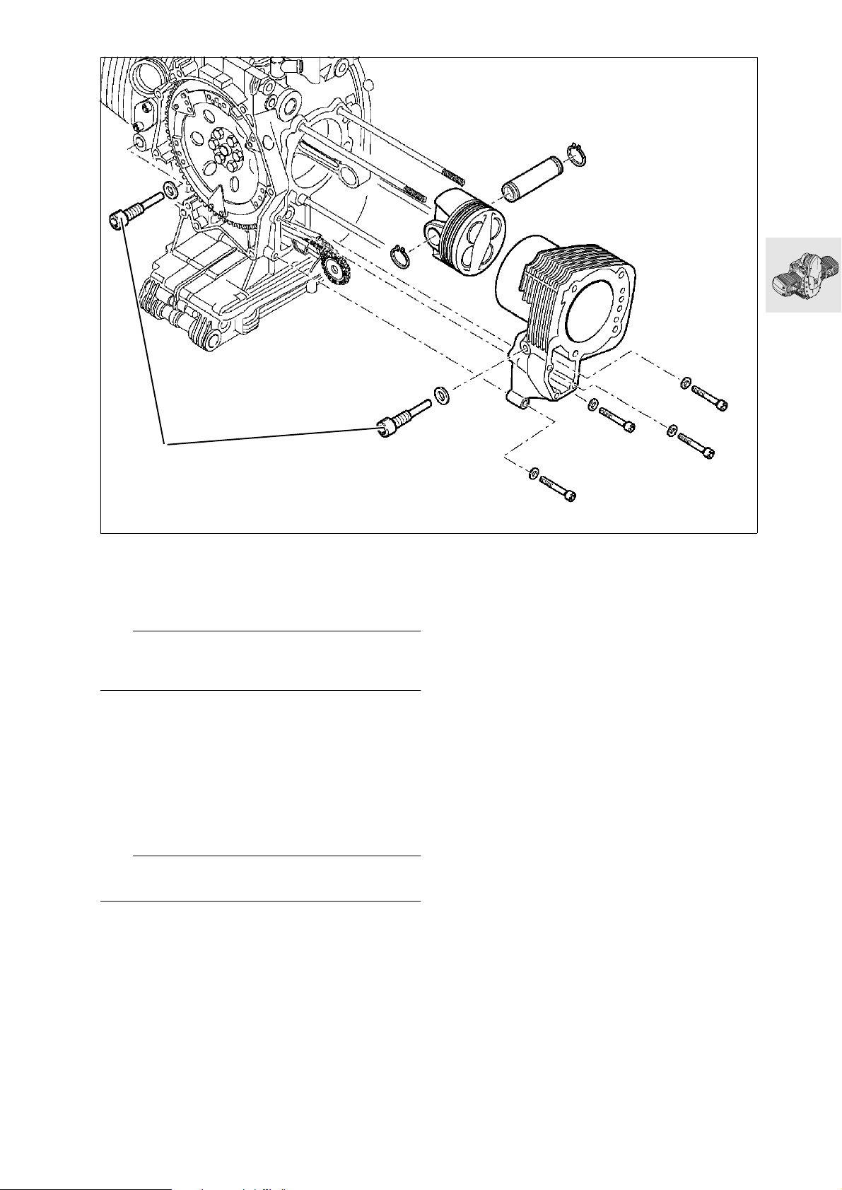
1
Removing cylinder
Remove guide rail bearing screws (1).
•
Remove cylinder retaining screws, and remove
•
cylinder.
e Caution:
When removing cylinder, make sure that the piston
does not strike the engine block.
Removing and disassembling piston
Remove both retaining rings from piston pin.
•
Press out piston pin by hand.
•
Remove piston.
•
Carefully remove piston rings with piston ring pli-
•
ers.
Remove combustion residues from piston crown
•
and clean piston.
RS110170
e Caution:
Do not mix up pistons, piston pins and piston rings.
11.29
Page 76
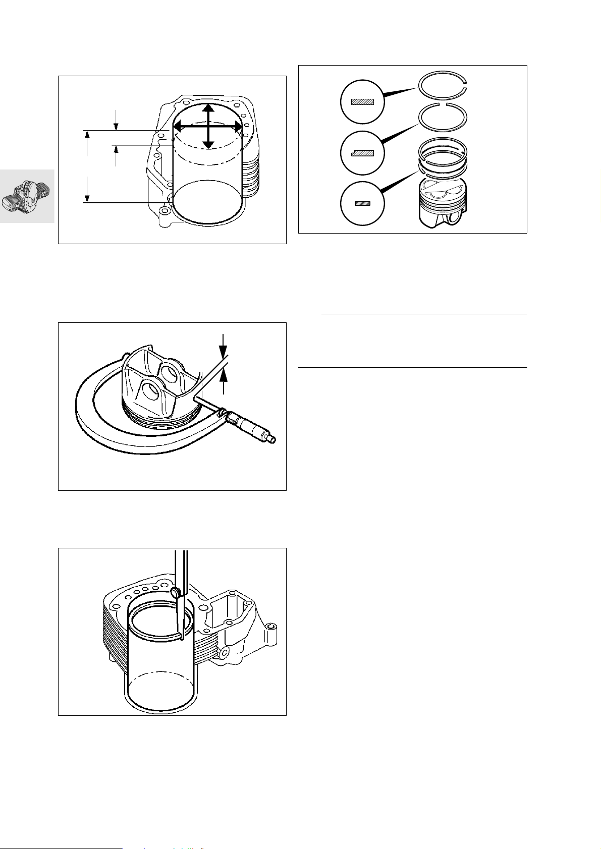
Checking pistons and cylinders
Reference temperature for measurements:
...........................................................20 °C (68 °F)
20
100
RS110180
Measure cylinder bore with internal probe at
•
20 mm (0.79 in) and 100 mm (3.94 in) from the
top in direction of piston pin, and again at a right
angle to the first measurement.
a ............................................See Technical Data
A
Assembling pistons
1.
TOP
2.
3.
S110170
Carefully fit piston rings to piston in the following
•
sequence, using piston ring pliers:
3rd groove - 3-S ring
2nd groove - micro-chamfer ring
1st groove - asymmetric piston ring, oval section
a ............................................See Technical Data
L Note:
Make sure that the gap of the spring in the 3-S ring
is offset approximately 180° from the gaps of the oil
control rings.
RS110970
Measuring plane A: .........................6 mm (0.24 in)
a ............................................See Technical Data
Install piston rings in cylinder.
•
RS110200
Measure end gap using feeler gauge.
•
a ............................................See Technical Data
11.30
Page 77
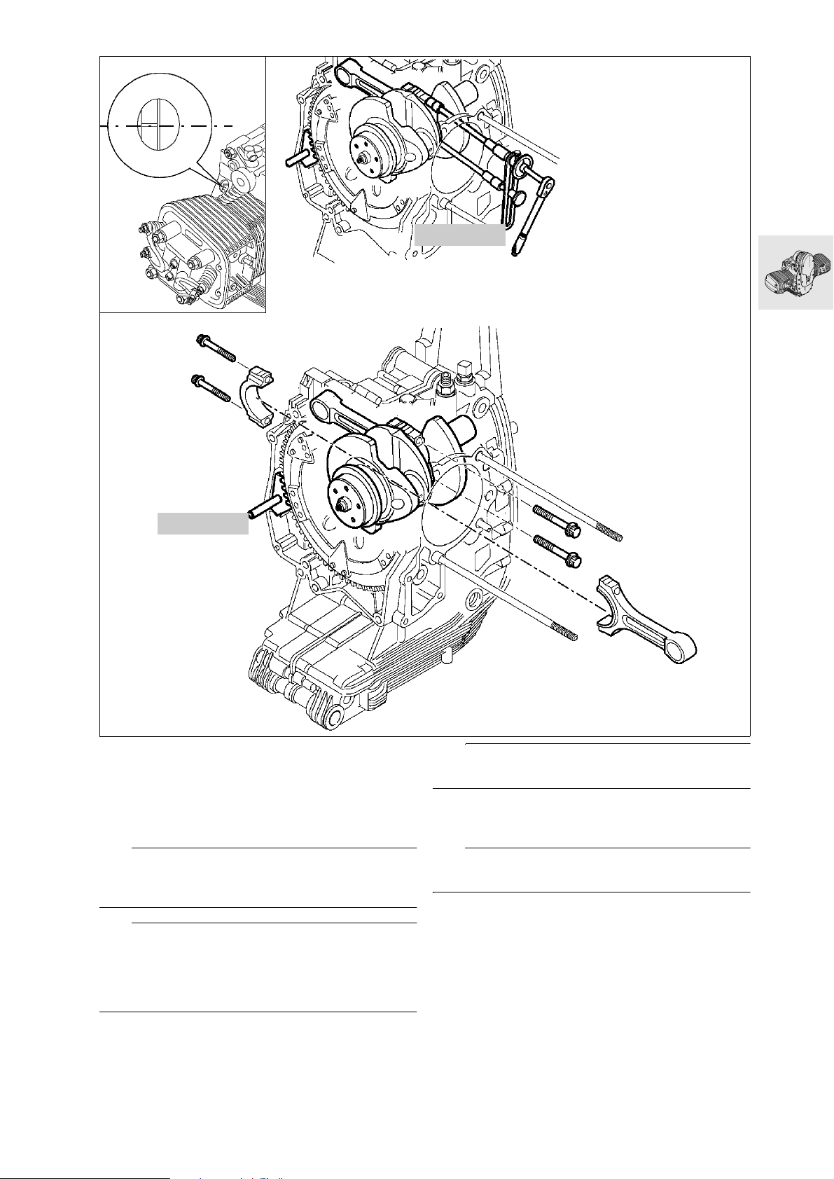
TDC
11 2 500
11 5 640
Removing and installing conrod
Turn crankshaft to TDC position.
•
Lock the clutch housing with special tool,
•
BMW No. 11 5 640.
Remove conrods.
•
L Note:
Conrods can also be removed and installed with the
crankshaft removed.
e Caution:
Make sure that conrods and bearing shells are reinstalled in their original positions.
Use a felt-tipped pen or similar to mark the installed
positions on the conrods.
RS110210
e Caution:
Oil the bearings.
Screw the big end bolts in by hand, then tighten
•
them with a tightening angle indicator,
BMW No. 11 2 500.
e Caution:
Never re-use the big end bolts.
X Tightening torque:
Big end bolts oiled
Joint torque.................................................. 20 Nm
Wrench angle.................................................... 80°
Install conrods.
•
11.31
Page 78
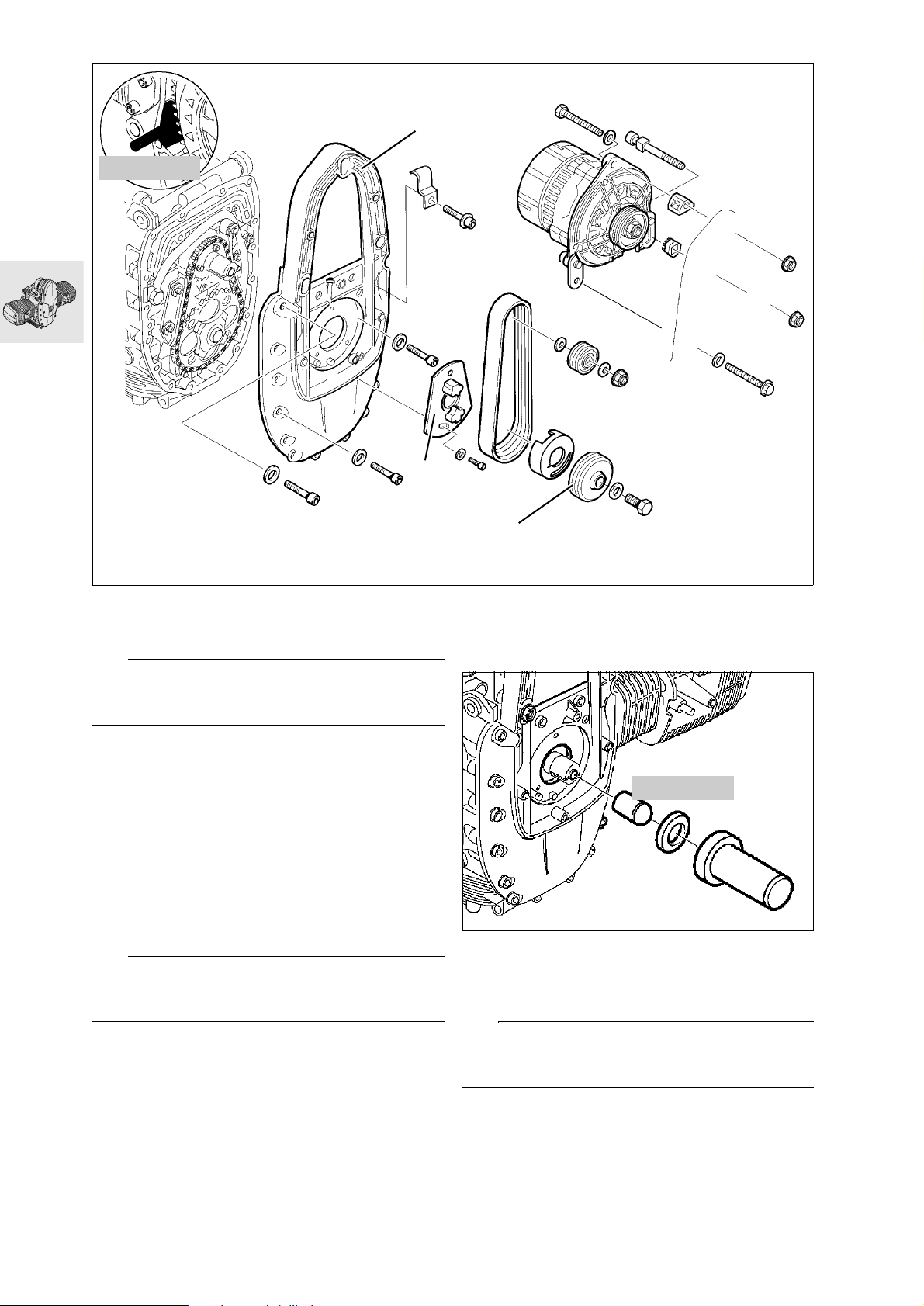
11 5 640
3
2
1
S110020
Removing and installing alternator mount
cover with engine installed
e Caution:
Disconnect earth (ground) lead from battery.
Insulate earth (ground) lead.
Remove the horn.
•
Remove the oil cooler line.
•
Disconnect the Hall sensor.
•
Remove the starter motor.
•
Remove rear leading link mount.
•
Removing alternator mount cover
Remove the alternator.
•
Lock the clutch housing with special tool,
•
BMW No. 11 5 640.
Remove pulley (1).
•
Remove magnetic gate (2).
•
L Note:
It is not necessary to remove magnetic gate (2) when
removing the alternator mount cover as a unit.
Remove alternator mount cover (3).
•
Replacing radial shaft seal in alternator
mount cover
11 5 680
RS110240
Carefully lever out radial shaft seal, using a
•
screwdriver.
Drive in the new radial shaft seal with drift and
•
sliding sleeve, BMW No. 11 5 680.
L Note:
Slide new radial shaft seal over taper on sliding
sleeve, pre-shape and pull off.
11.32
Page 79
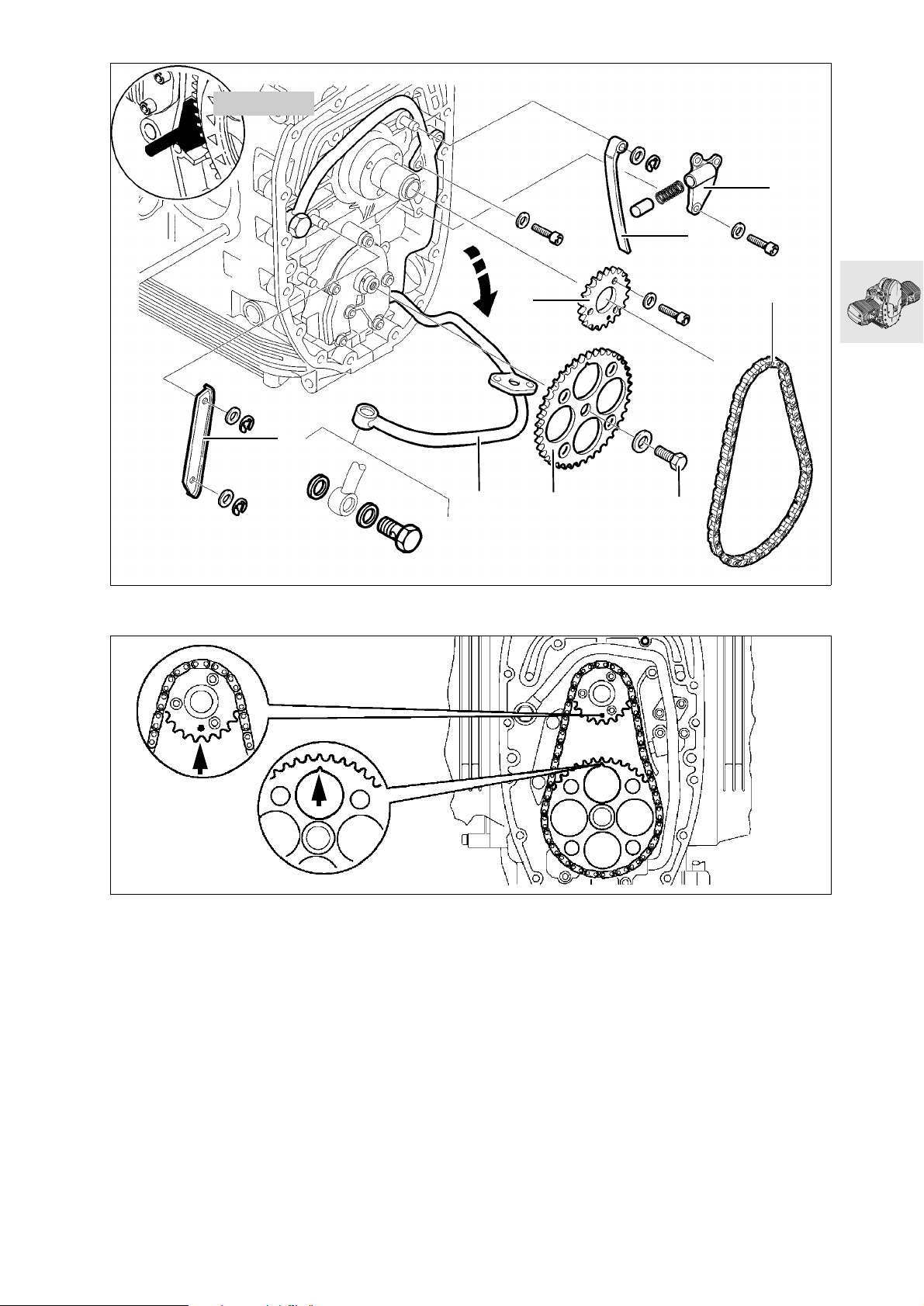
11 5 640
2
3
4
Removing auxiliary shaft drive
8
1
6
5
7
S110030
Align marks (arrows) on timing pinion and chain
•
sprocket.
Remove banjo bolt of cooling oil pipe (1) and
•
swing the pipe forwards.
Remove chain tensioner (2).
•
Remove chain tensioning rail (3).
•
Remove chain guide rail (4).
•
Lock the clutch housing with special tool,
•
BMW No. 11 5 640.
Remove chain sprocket retaining bolt (5).
•
Remove sprocket (6) and timing chain (7).
•
If necessary, remove chain sprocket (8).
•
S110120
11.33
Page 80
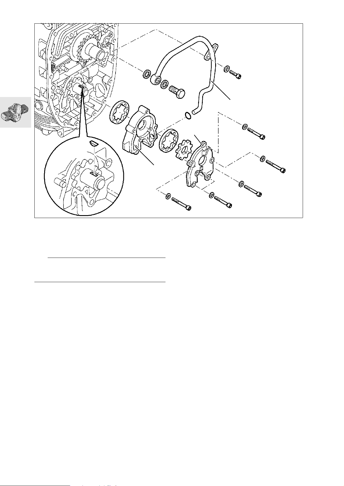
3
1
M6 x 45
Removing oil pump
Remove oil pump cover (1).
•
Remove complete oil pump (2) together with
•
cooling oil pipe (3), and disassemble.
e Caution:
Check installed positions of parts which have already been run together.
2
M6 x 50
M6 x 45
M6 x 50
M6 x 45
RS110410
11.34
Page 81
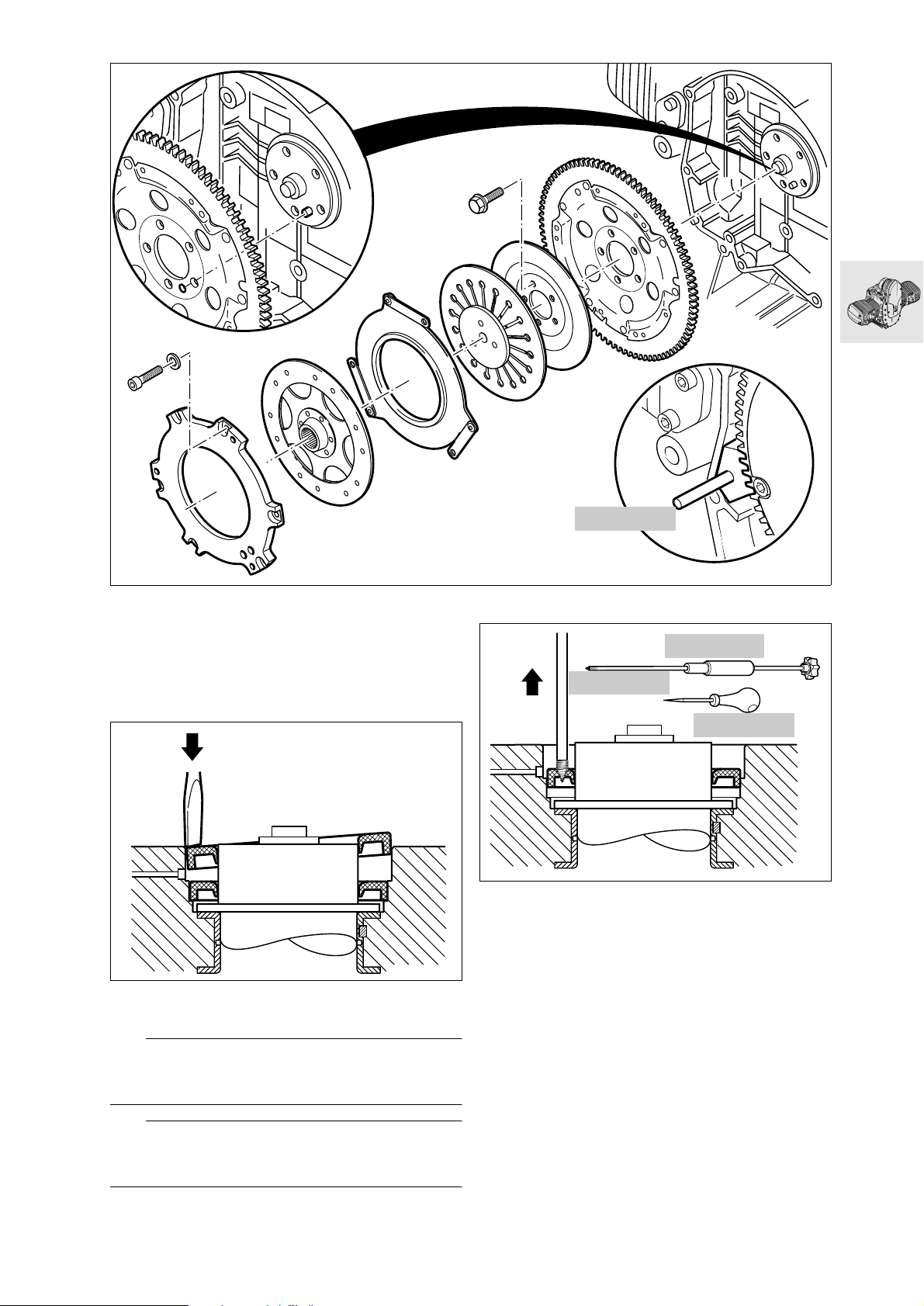
Removing radial shaft seal from
crankshaft with engine installed
Lock clutch housing with special tool,
•
BMW No. 11 5 640.
Remove the clutch.
•
S110040
11 5 640
S210010
00 8 582
00 8 581
00 8 583
S110100
Using awl, BMW No. 00 8 583, carefully punch a
•
hole in the shaft sealing ring.
Screw the pull rod, BMW No. 00 8 581, into the
•
hole and use impact weight, BMW No. 00 8 582,
to remove the shaft sealing ring.
Carefully lever out radial shaft seal, using a
•
screwdriver.
e Caution:
Take care not to damage the sealing faces of crankcase and crankshaft.
L Note:
The radial shaft seals can be removed when the
crankcase is disassembled.
11.35
Page 82
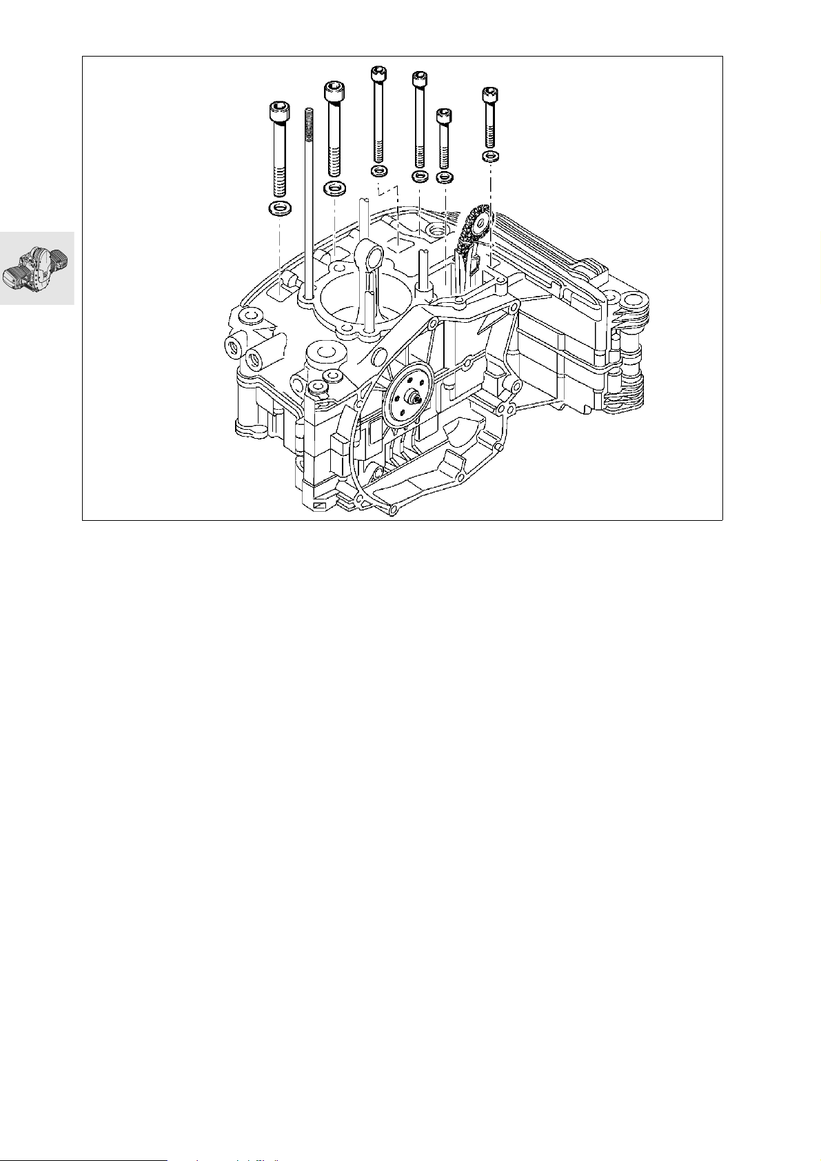
M8 x 80
M8 x 80
M10 x 100‹
M10 x 100‹
M8 x 35
M8 x 35
RS110261
Disassembling crankcase
Turn engine on to its side.
•
Remove screws on right side.
•
11.36
Page 83
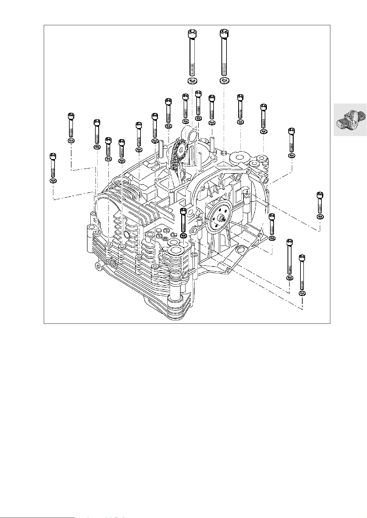
M6 x 50
M6 x 35
M10 x 100‹
M6 x 35
M6 x 35
M6 x 50
M6 x 25
M10 x 100‹
M6 x 50
M6 x 50
M6 x 50
M6 x 50
M6 x 25
M6 x 25
M6 x 35
M6 x 35
M6 x 35
Turn engine on to its side.
•
Remove screws on left side.
•
Remove upper section of crankcase.
•
M6 x 50
M6 x 35
M6 x 50
M6 x 50
RS110260
11.37
Page 84
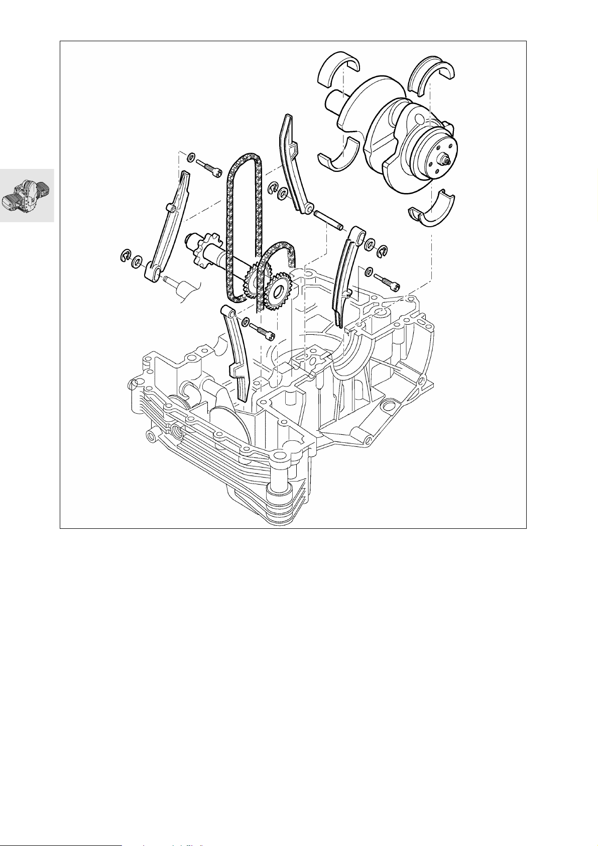
Removing crankshaft, auxiliary shaft
and timing chain tensioning and slide
rails
11.38
S110050
Page 85
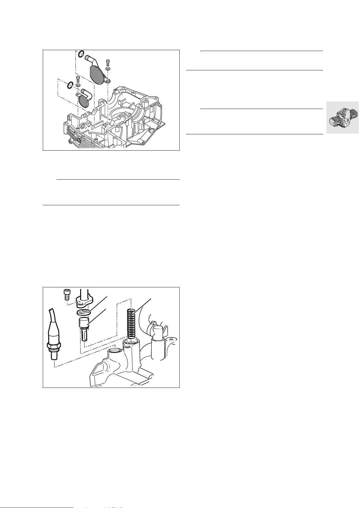
Removing and installing oil intake strainers
S110060
X Tightening torque:
M 6 screw ......................................................9 Nm
e Caution:
Make sure that the O-ring is not omitted, and is installed undamaged.
Removing conrods
Clamp crankshaft in a vise with protective jaws.
•
Remove conrod.
•
e Caution:
Do not mix up the conrods.
Checking conrods
Check conrod dimensions.
•
a ........................................... See Technical Data
e Caution:
Do not attempt to straighten the sintered conrods –
risk of fracture.
Replacing oil level sight glass
Pierce the plastic disc with a large screwdriver
•
and lever out the oil level sight glass.
Coat the sealing face of the new oil level sight
•
glass with engine oil and drive it in with drift,
BMW No. 00 5 550.
Removing and installing oil thermostat
1
3
2
S110070
Remove screws securing oil cooler line to fairing
•
bracket.
Disconnect oil cooler line from crankcase.
•
Remove support plate (1), control element (2)
•
and spring (3).
Installation is the reverse of the removal proce-
•
dure.
X Tightening torque:
M 6 screw ......................................................9 Nm
11.39
Page 86
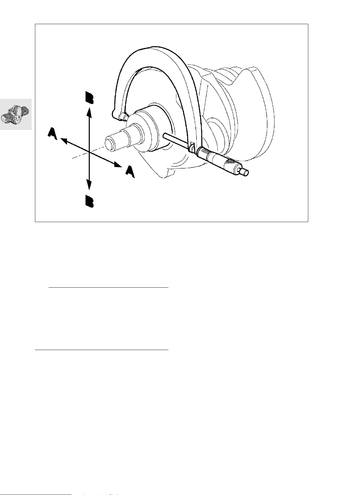
Measuring crankshaft bearing play
Measuring radial bearing play
Measure main bearing journal with an external
•
micrometer in two planes, A and B, at right angles.
Enter measured values on record sheet.
•
a ........................................... See Technical Data
e Caution:
The crankshaft can only be reground in grinding
stage 0; after this it must be rehardened and finished. Grinding stages are identified by a paint mark
on the front crank web.
a ................................ See Technical Data
When replacing the bearing shells, make sure that
the colour marks on the crankpins and big end bearings match.
RS110310
11.40
Page 87
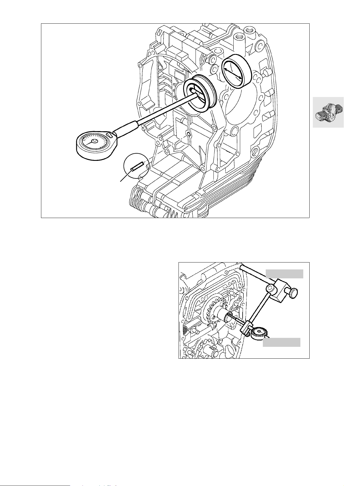
1
RS110320
Installing main bearings
Insert tensioner rail/slide rail pivot pin (1) for
•
centering purposes.
Tighten M 8 and M 10 crankcase screws.
•
X Tightening torque/tightening order:
1. M 10 screw (oiled) Initial torque ......... 25 Nm
Wrench angle............ 90°
2. M 8 screw (oiled)......................................22 Nm
Measure front and rear main bearings in the load
•
direction.
Enter measured values on record sheet and cal-
•
culate main bearing play.
a ........................................... See Technical Data
Measuring axial bearing play
Place crankshaft in crankcase.
•
Insert tensioner rail/slide rail pivot pin (1) for
•
centering purposes.
Tighten crankcase screws.
•
00 2 500
00 2 510
RS110910
Screw measuring device, BMW No. 00 2 500,
•
with dial gauge, BMW No. 00 2 510, into tapped
hole for alternator carrier cover.
Move crankshaft forwards and backwards and
•
read axial play from dial gauge.
a ........................................... See Technical Data
11.41
Page 88
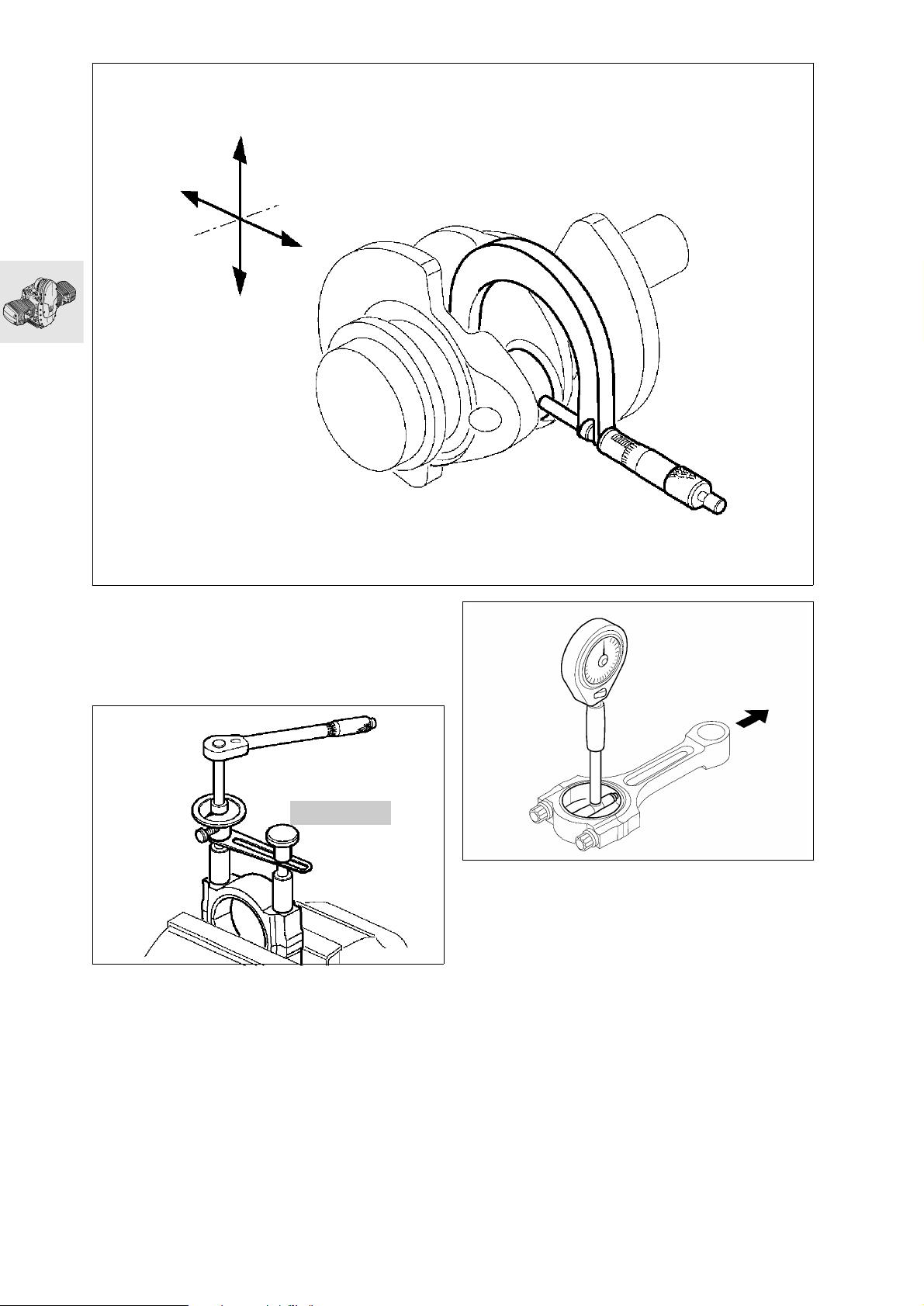
Measuring big end bearing play
Measure crankpin with an external micrometer in
•
the thrust direction and at right angles to the
thrust direction.
11 2 210
RS110350
Install bearing shells and assemble conrods.
•
Using tightening angle indicator,
•
BMW No. 11 2 210, tighten the big end bolts.
RS110340
RS110360
Measure big end bearing with internal gauge in
•
thrust direction.
Enter measured values on record sheet and cal-
•
culate big end bearing play.
a ........................................... See Technical Data
X Tightening torque:
Big end bolts oiled
Joint torque..................................................20 Nm
Wrench angle.................................................... 80°
11.42
Page 89
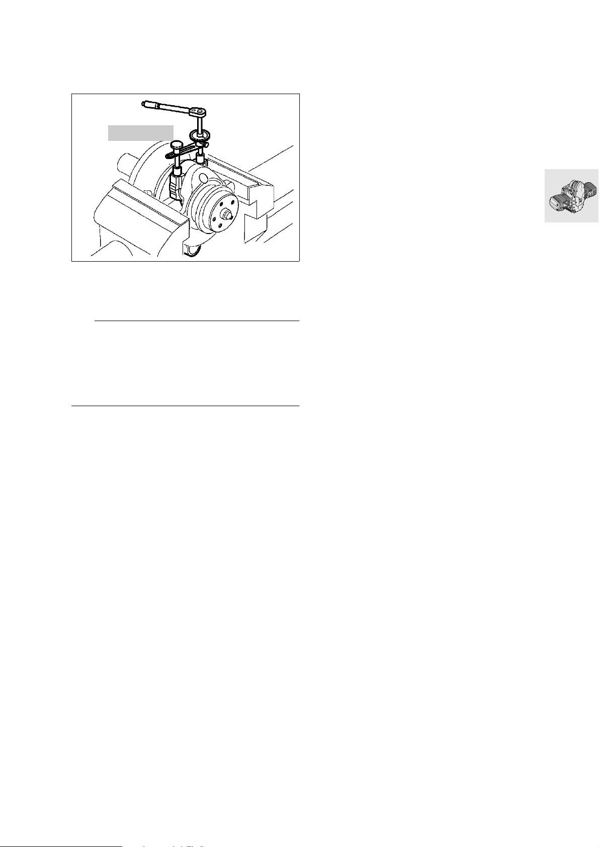
Assembling engine
Installing conrods
11 2 500
RS110370
Clamp crankshaft in a vise with protective jaws.
•
Oil the big end bolts, screw them in by hand and
•
tighten with tightening angle indicator,
BMW No. 11 2 500.
e Caution:
Oil the bearings.
Make sure that conrods and bearing shells are reinstalled in their original positions.
Always use new big end bolts.
Use a felt-tipped pen or similar to mark the installed
positions on the conrods.
X Tightening torque:
Big end bolts (oiled)
Joint torque.................................................. 20 Nm
Wrench angle.................................................... 80°
11.43
Page 90
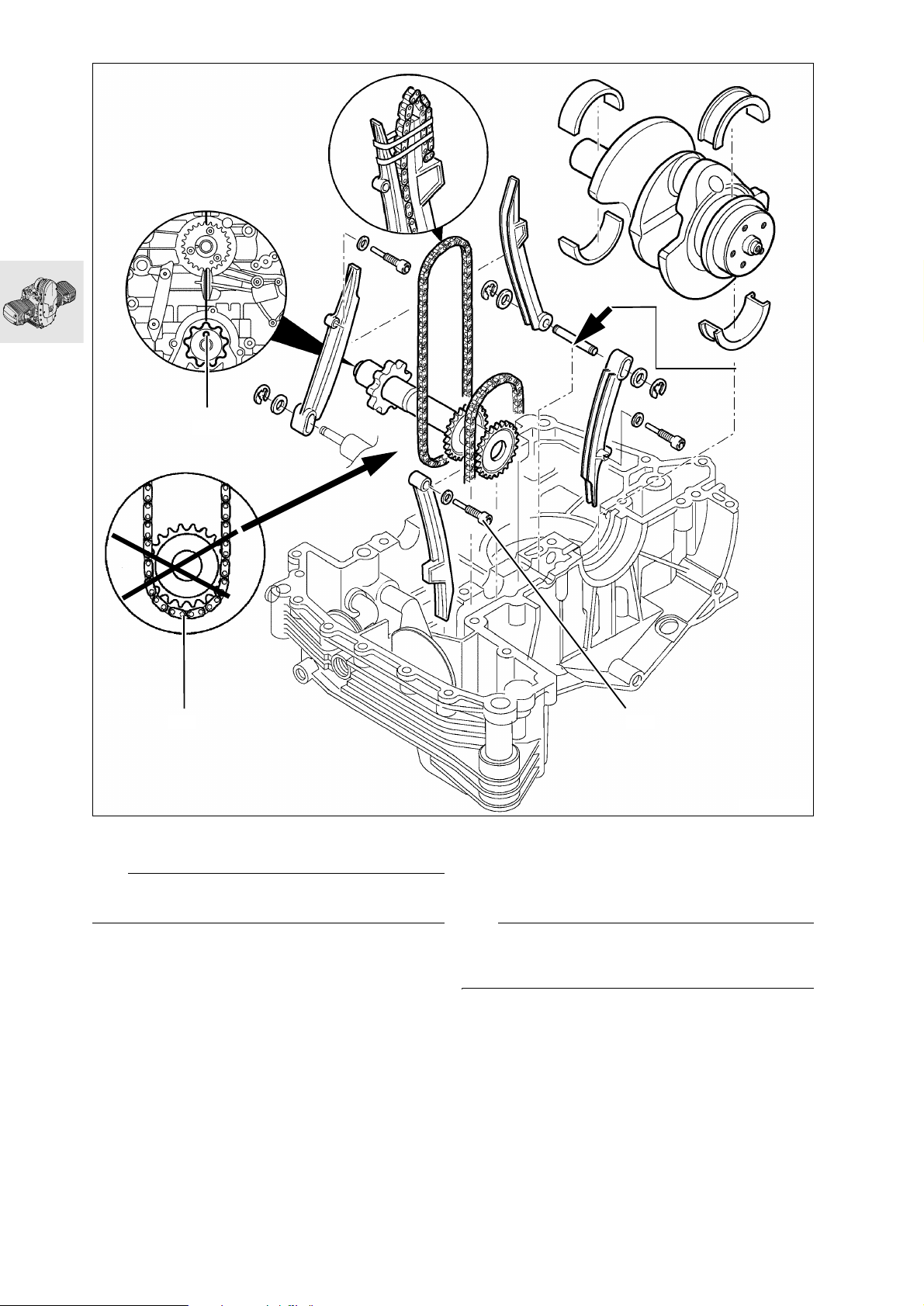
u
2
3
Installing crankshaft
e Caution:
Oil the bearings.
Installing timing chain tensioning and
slide rails
Seal pivot pin for tensioner rail/slide rail at clutch
•
side (arrow) with 3-Bond 1209.
Insert pivot screw (1) into chain tensioner rail, us-
•
ing a new seal.
X Tightening torque:
Chain guide rail pivot pin..............................18 Nm
1
S110080
Installing auxiliary shaft/timing chains
When installing the auxiliary shaft, make sure that
•
the bore in the auxiliary shaft (2) facing the crankshaft is in line with the crankcase mating face.
e Caution:
Timing chains (3) must mesh fully with auxiliary shaft
sprockets.
11.44
Page 91
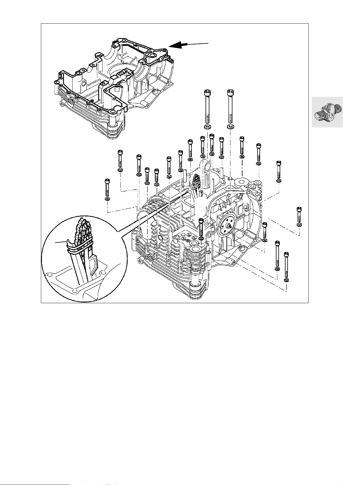
u
M10 x 100‹
M6 x 50
M6 x 50
M6 x 50
M6 x 50
M6 x 50
M6 x 25
M6 x 25
M6 x 35
M6 x 35
M6 x 35
M6 x 50
1
M10 x 100‹
M6 x 35
M6 x 35
M6 x 35
M6 x 50
M6 x 25
M6 x 35
M6 x 50
M6 x 50
Assembling engine block
Clean and degrease sealing faces (arrow) and
•
coat with 3-Bond 1209.
Secure the timing chain with rubber band (1) to
•
the timing chain tensioner and slide rail.
RS110920
11.45
Page 92
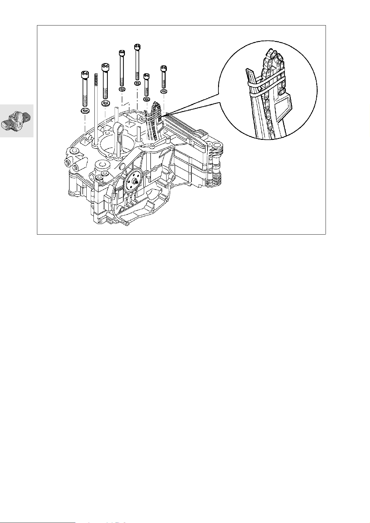
M8 x 80
M8 x 80
M10 x 100‹
M10 x 100‹
M8 x 35
M8 x 35
RS110391
Bolt the crankcase sections together.
•
X Tightening torque/tightening order:
1. M 10 screw (oiled) Initial torque .......... 25 Nm
Wrench angle............. 90°
2. M 8 screw (oiled)......................................22 Nm
3. M 6 screw .................................................. 9 Nm
11.46
Page 93
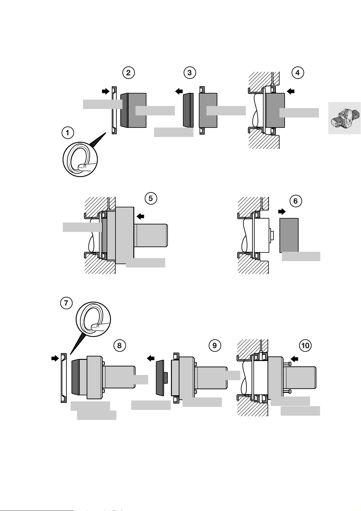
11 5 702
11 5 703
11 5 703
11 5 701
11 5 702
11 5 703
11 5 703
11 5 703
11 5 662
11 5 661
00 5 500
11 5 662
00 5 500
11 5 661
11 5 661
00 5 500
11.47
Page 94

Installing radial shaft seals on crankshaft
Installing the crankshaft-end radial shaft seal
Shape the lip of the radial shaft seal carefully by
•
hand (1).
Oil the radial shaft seal at the sealing/contact
•
surface.
Using assembly sleeve, BMW No. 11 5 702,
•
mount the radial shaft seal with the closed side
toward the clutch onto sleeve,
BMWNo.115703, (2).
Remove assembly sleeve (3).
•
Mount sleeve complete with radial shaft seal on
•
crankshaft (4).
Use drift, BMW No. 11 5 701, together with the
•
sleeve (5) to drive the radial shaft seal onto the
crankshaft.
Remove sleeve (6).
•
Installing the clutch-end radial shaft seal
Shape the lip of the radial shaft seal carefully by
•
hand (7).
Oil the radial shaft seal at the sealing/contact
•
surface.
Using assembly sleeve, BMW No. 11 5 662,
•
mount the radial shaft seal with the closed side
toward the clutch onto drift, BMW No. 11 5 661,
with handle, BMW No.005500, (8).
Remove assembly sleeve (9).
•
Using the drift, drive the radial shaft seal
•
home (10).
11.48
Page 95
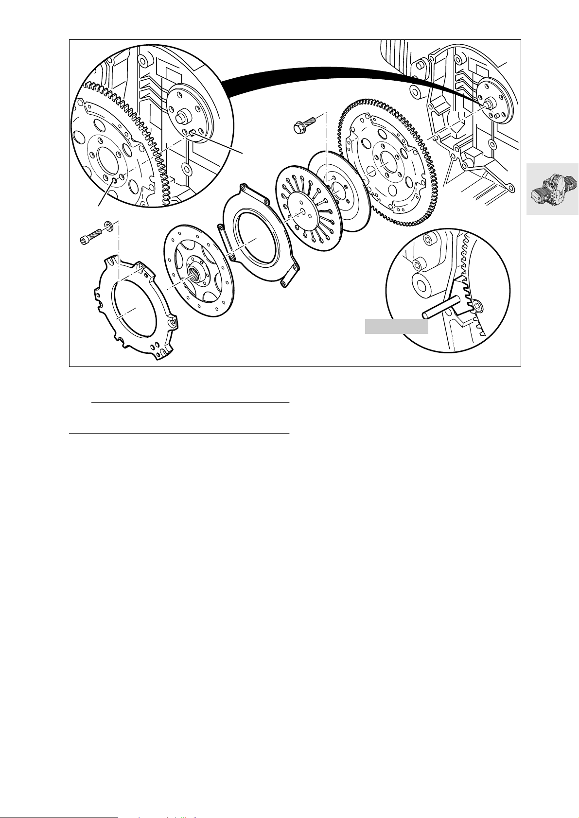
2
1
Installing clutch housing
e Caution:
Always use new screws for housing and cover.
11 5 640
S210010
Install clutch housing with mark (1) aligned with
•
crankshaft mark (2).
Lock the clutch housing with special tool,
•
BMW No. 11 5 640.
Insert all screws by hand and tighten down.
•
X Tightening torque:
Clutch housing to crankshaft
(screw threads oiled) ...................................40 Nm
Wrench angle.................................................... 32°
11.49
Page 96
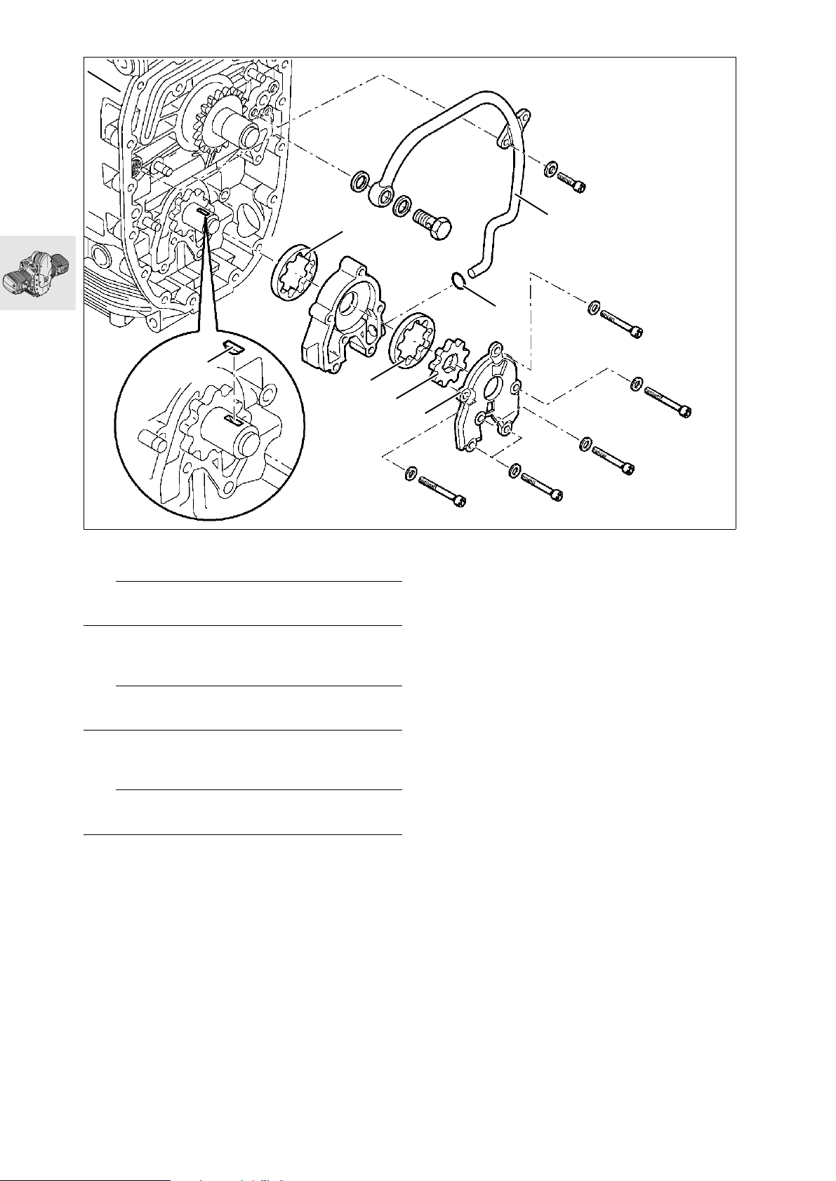
1
2
3
M6 x 45
4
5
5
6
7
M6 x 45
M6 x 50
Installing oil pump
e Caution:
Oil the friction faces.
Install outer rotor (1) of oil pump in pump hous-
•
ing.
Install oil pump housing with cooling oil pipe (2).
•
e Caution:
O-ring (3) must be in perfect condition.
Install Woodruff key (4), outer rotor (5) and inner
•
rotor (6) in cooling oil pump.
Secure housing cover (7) to oil pump.
•
e Caution:
Note different lengths of screws.
X Tightening torque:
M 6 screw ...................................................... 9 Nm
Pressure relief valve ..................................... 42 Nm
Oil pressure switch....................................... 30 Nm
M6 x 50
M6 x 45
RS110411
11.50
Page 97
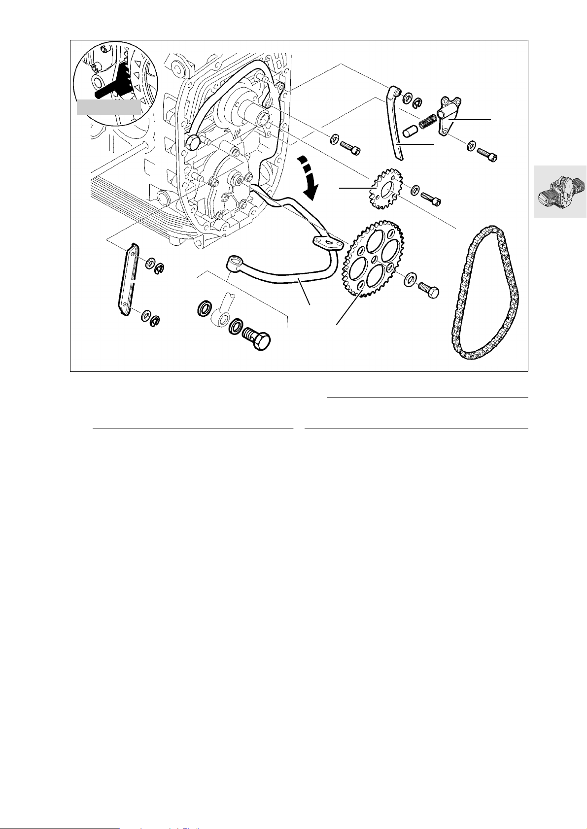
11 5 640
5
4
1
3
6
2
S110030
Installing auxiliary shaft drive
Align crankshaft mark with mark on auxiliary
•
shaft.
e Caution:
Adjust according to the adjusting instructions.
b ............................................ See Technical Data
Lock the clutch housing with special tool,
•
BMW No. 11 5 640.
Install chain sprocket (1).
•
X Tightening torque:
M 6 screw .................................................... 10 Nm
Install drive-shaft chain with chainwheel (2).
•
X Tightening torque:
Securing screw in chainwheel...................... 70 Nm
Install and secure chain guide rail (3).
•
Install and secure chain tensioner rail (4).
•
Install chain tensioner housing (5) with piston and
•
spring.
X Tightening torque:
M 6 screw ......................................................9 Nm
Tighten down cooling oil line (6).
•
e Caution:
Use a new sealing ring.
X Tightening torque:
M 6 screw.................................................... 10 Nm
Banjo bolt for cooling oil line
with oil vent valve ......................................... 25 Nm
11.51
Page 98
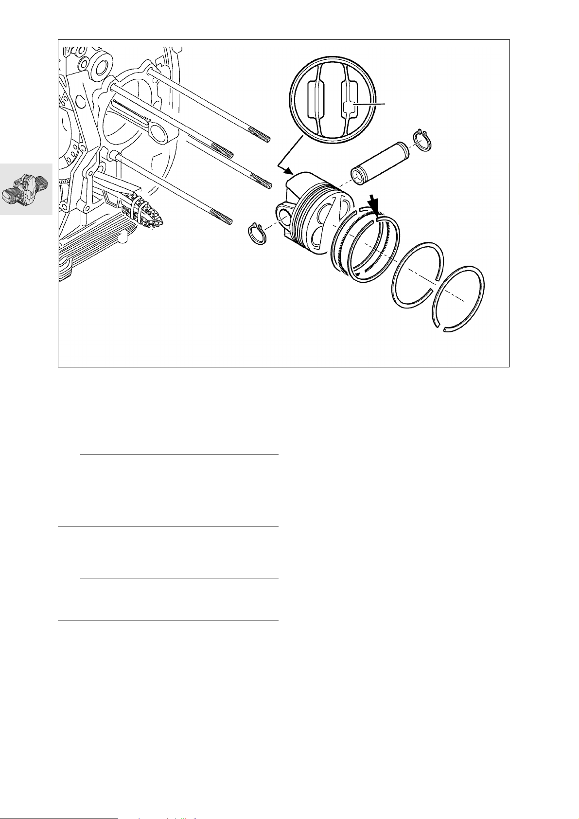
Installing piston
X
RS110430
Turn oil scraper ring so that gap (arrow) is at top.
•
Install piston rings with gaps offset by 120°.
•
Production locating point X = install on exhaust side.
e Caution:
Make sure that retaining rings are properly seated
on piston pin.
Oil the friction faces.
Always use pistons of the same weight class in any
one engine.
Markings: .................................................... + or —
a ........................................... See Technical Data
e Caution:
Always install pistons and cylinders in pairs.
Do not mix up pistons and piston pins.
Piston size identification:
On piston crown A, B, AB (for either A or B cylinder),
and on cylinder A, B.
11.52
Page 99
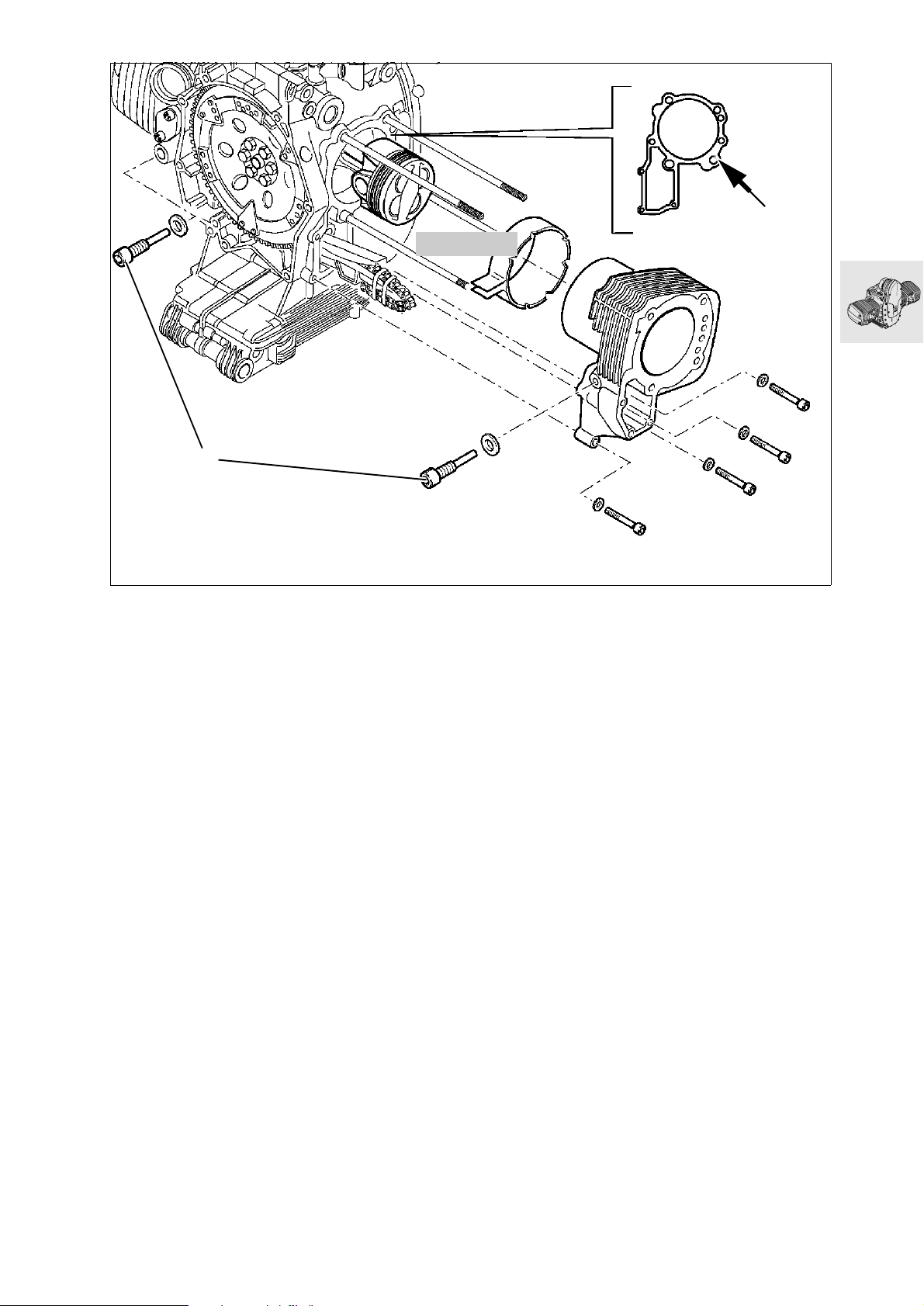
1
Installing cylinder
Clean and de-grease cylinder base sealing face
•
(arrow) and apply 3-Bond 1209.
Oil the cylinder wall.
•
Compress the piston rings with a clamping strap,
•
BMW No. 11 2 900.
Install the cylinder and at the same time pass the
•
timing chain and the tensioner and guide rails
through the timing case cavity.
Tighten cylinder securing screws.
•
Fit new seals to pivot pins for chain guide rail (1).
•
Install chain sprocket.
•
u
11 2 900
RS110420
X Tightening torque/tightening sequence:
1. M 8 screw ................................................ 20 Nm
2. M 6 screw .................................................. 9 Nm
3. Pivot screw for chain guide rail.................... 18 Nm
11.53
Page 100
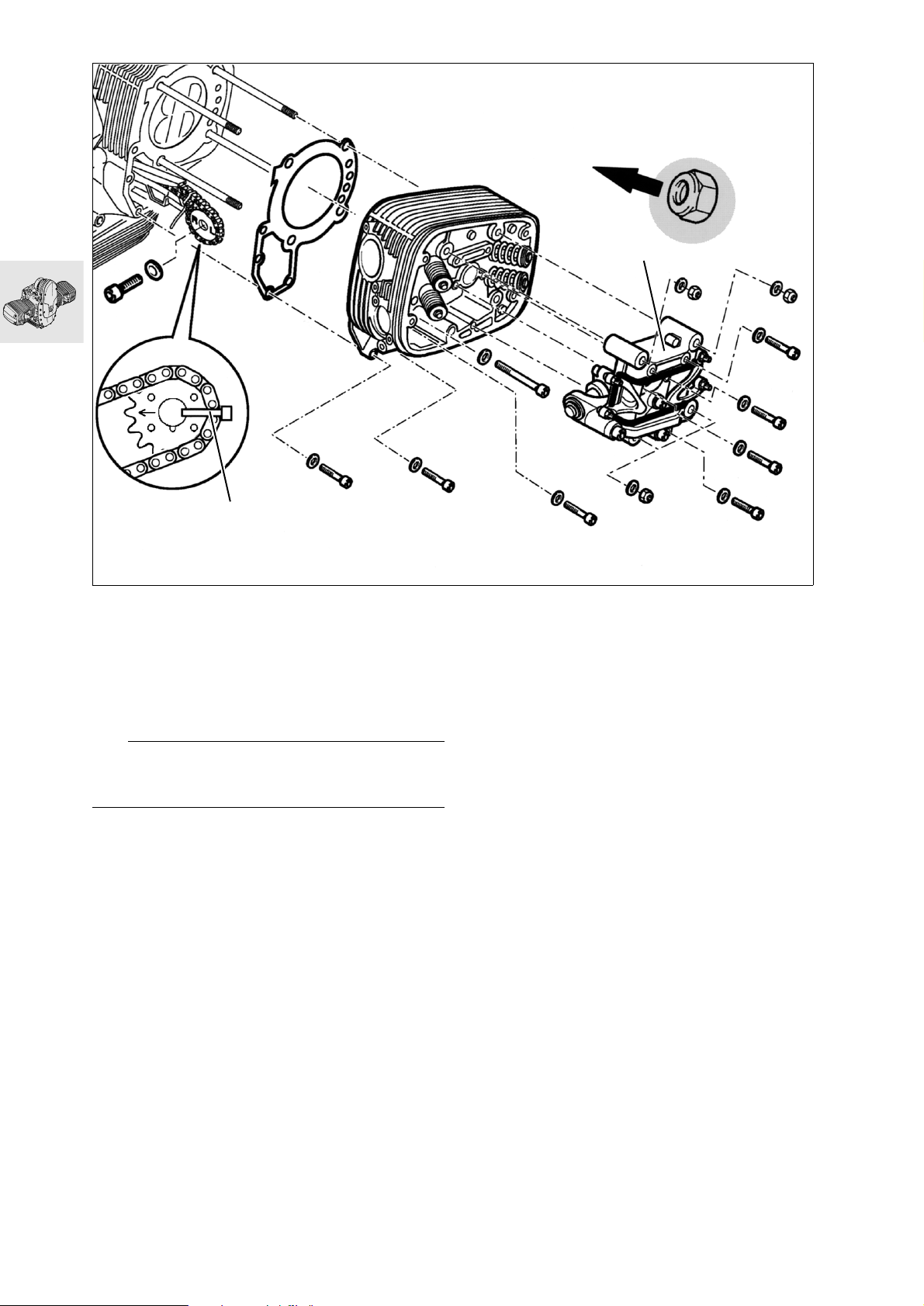
2
M6 x 60
M6 x 30
M6 x 30
1
Installing cylinder head
Install cylinder head gasket.
•
Fit cylinder head and insert correctly positioned
•
camshaft chain sprocket (1) and timing chain into
chain cavity.
Install valve gear holder (2).
•
Tighten cylinder head securing screws and nuts.
•
e Caution:
Install cylinder head nuts with collar (arrow) toward
cylinder head.
X Tightening torque/tightening sequence:
1. Tighten cylinder head nuts (oiled) in diagonally
opposite sequence
1.1 Tighten all nuts....................................... 20 Nm
1.2 Tighten all nuts to correct angle.................. 90°
1.3 Tighten all nuts to correct angle.................. 90°
2. M 10 screw ............................................ 40 Nm
3. M 6 screw ................................................ 9 Nm
M6 x 30
S110130
Fit camshaft chain sprocket in accordance with
•
adjustment specification.
Lock the clutch housing with special tool,
•
BMW No. 11 5 640.
Tighten camshaft chain sprocket.
•
X Tightening torque:
Camshaft sprocket retaining screw.............. 65 Nm
Insert the left-side camshaft sprocket with pin
•
into the camshaft and set the left cylinder to firing
TDC.
Fit camshaft chain sprocket in accordance with
•
adjustment specification.
Tighten camshaft chain sprocket.
•
Install chain tensioner.
•
Check that marks on camshaft sprockets are in
•
accordance with adjustment specification.
X Tightening torque:
Chain tensioner............................................ 32 Nm
X Tightening torque:
Retighten after 1000 km (app. 600 miles)
Tighten cylinder head nuts in diagonally opposite
sequence
1. Slacken one nut
2. Tighten nut to initial torque......................20 Nm
3. Tighten nut to wrench angle...................... 180°
4. Slacken and retighten M10 screw ...........40 Nm
11.54
 Loading...