

Page 1
Rider's Manual (US Model)
S 1000 RR
BMW Motorrad
bmw‑motorrad.com
The Ultimate
Riding Machine
Page 2

Motorcycle/Retailer Data
Motorcycle Data
Model
Vehicle identification number
Color number
Initial registration
License plate
Retailer Data
Contact in Service
Ms./Mr.
Phone number
Retailer's address/phone number (company stamp)
Page 3

Welcome to BMW
Congratulations on choosing a
motorcycle from BMW Motorrad
and welcome to the community
of BMW motorcycle owners and
riders. Familiarize yourself with
your new motorcycle so that you
can ride it safely and confidently
in all highway traffic situations.
About this Rider's Manual
Please read this Rider's Manual
carefully before starting to use
your new BMW. It contains important information on how to
operate the controls and how to
get the most benefit from your
BMW's advanced technical features.
In addition, it contains information
on maintenance and care to help
you maintain your motorcycle's
reliability and safety, as well as its
value.
Documentation confirming performance of scheduled maintenance is a precondition for generous handling of out-of-warranty
claims and goodwill warranty
treatment.
Should you want to sell your
BMW one day, please also remember to turn over the Ride's
Manual to the new owner. it is
an important part of your motorcycle.
Suggestions and complaints
If you have any questions concerning your motorcycle, your authorized BMW Motorrad retailer
is always happy to provide advice
and assistance.
We wish you many miles of safe
and enjoyable riding on your
BMW
BMW Motorrad.
01 41 8 569 547
*01418569547*
Page 4

Table of Contents
1 General instructions . ... 5
Overview .. . . . . . . . . . . . . . . . . . . . 6
Abbreviations and
symbols .. . . . . . . . . . . . . . . . . . . . . 6
Equipment . . . . . . . . . . . . . . . . . . . 7
Technical data . . . . . . . . . . . . . . . 7
Notice concerning current sta-
tus . . . . . . . . . . . . . . . . . . . . . . . . . . . 7
2 Overviews . .. .. .. .. . .. .. .. 9
General view, left side . . . . . . . 11
General view, left side with
DDC . . . . . . . . . . . . . . . . . . . . . . . . 13
General view, right side . . . . . 15
Underneath seat . . . . . . . . . . . . 16
Multifunction switch, left . . . . 17
Multifunction switch,
right . . . . . . . . . . . . . . . . . . . . . . . . . 19
Instrument cluster . . . . . . . . . . . 20
3 Displays . . .. .. .. .. . .. .. .. 21
Indicator and warning
lights . . . . . . . . . . . . . . . . . . . . . . . . 22
Multifunction display . . . . . . . . 23
ABS Pro display . . . . . . . . . . . . . 24
Warning lights . . . . . . . . . . . . . . . 24
4 Operation . .. . .. .. .. .. .. .. 39
Steering and ignition
lock . . . . . . . . . . . . . . . . . . . . . . . . . 40
Electronic immobilizer . . . . . . . 41
Emergency on/off switch (kill
switch) . . . . . . . . . . . . . . . . . . . . . . 41
Lights . . . . . . . . . . . . . . . . . . . . . . . 42
Hazard warning flashers . . . . . 43
Turn indicators . . . . . . . . . . . . . . 43
Multifunction display . . . . . . . . 45
Clock . . . . . . . . . . . . . . . . . . . . . . . . 48
Anti-theft alarm (DWA) . . . . . . 48
Antilock Brake System
(ABS). . . . . . . . . . . . . . . . . . . . . . . . 50
Automatic Stability Control
(ASC) . . . . . . . . . . . . . . . . . . . . . . . 51
Dynamic Traction Control
(DTC) . . . . . . . . . . . . . . . . . . . . . . . 52
Riding mode . . . . . . . . . . . . . . . . 53
Cruise control . . . . . . . . . . . . . . . 57
Speed warning . . . . . . . . . . . . . . 59
Heated handlebar grips . . . . . 60
Rider and passenger
seats . . . . . . . . . . . . . . . . . . . . . . . . 61
Helmet holder . . . . . . . . . . . . . . . 63
Luggage straps . . . . . . . . . . . . . 64
5 Setting .. .. .. .. .. . .. .. .. .. 65
Mirrors . . . . . . . . . . . . . . . . . . . . . . 66
Headlight . . . . . . . . . . . . . . . . . . . . 66
Brakes . . . . . . . . . . . . . . . . . . . . . . 66
Steering . . . . . . . . . . . . . . . . . . . . . 67
Spring preload . . . . . . . . . . . . . . 67
Damping . . . . . . . . . . . . . . . . . . . . 72
DDC . . . . . . . . . . . . . . . . . . . . . . . . 75
6 Riding .. .. .. .. .. . .. .. .. .. . 79
Safety instructions . . . . . . . . . . 80
Checklist . . . . . . . . . . . . . . . . . . . . 81
Starting. . . . . . . . . . . . . . . . . . . . . . 82
Breaking in . . . . . . . . . . . . . . . . . . 86
Shifting gears . . . . . . . . . . . . . . . 87
Brakes . . . . . . . . . . . . . . . . . . . . . . 88
Page 5

Parking your motorcycle . . . . 90
Refueling . . . . . . . . . . . . . . . . . . . . 91
Secure motorcycle for trans-
port . . . . . . . . . . . . . . . . . . . . . . . . . 93
7 On the racetrack . .. .. .. . 95
Display for racing mode . . . . . 96
LAPTIMER . . . . . . . . . . . . . . . . . . 98
RACE INFO . . . . . . . . . . . . . . . 103
SETUP MENU . . . . . . . . . . . . 111
SETUP DDC-SYS. . . . . . . . . 117
SETUP EQUIPMENT . . . . . 118
SETUP RACETRACK . . . . . 120
SETUP USER-MODE . . . . . 125
DTC . . . . . . . . . . . . . . . . . . . . . . . 127
Start of race . . . . . . . . . . . . . . . 128
Speed limiter for pit
lane . . . . . . . . . . . . . . . . . . . . . . . 130
Mirror removal and installa-
tion . . . . . . . . . . . . . . . . . . . . . . . . 131
Removing and installing
license-plate carrier . . . . . . . 132
Removing and installing
front turn indicator . . . . . . . . 134
Shift pattern reversal . . . . . . 136
Connector for optional ac-
cessories . . . . . . . . . . . . . . . . . . 138
8 Technology in de-
tail . . .. .. .. .. . .. .. .. .. .. . 141
Antilock Brake System
(ABS). . . . . . . . . . . . . . . . . . . . . . 142
Dynamic Damping Control
(DDC) . . . . . . . . . . . . . . . . . . . . . 145
Dynamic Traction Control
(DTC) . . . . . . . . . . . . . . . . . . . . . 145
Riding mode . . . . . . . . . . . . . . 147
Pro shift assistant . . . . . . . . . 153
9 Maintenance . . . .. .. .. . 155
General instructions . . . . . . . 156
Onboard tool kit .. . . . . . . . . . 156
Front wheel stand . . . . . . . . . 157
Rear-wheel stand . . . . . . . . . 158
Engine oil . . . . . . . . . . . . . . . . . 159
Brake system . . . . . . . . . . . . . 161
Clutch . . . . . . . . . . . . . . . . . . . . . 165
Coolant. . . . . . . . . . . . . . . . . . . . 166
Tires . . . . . . . . . . . . . . . . . . . . . . 167
Wheel rims and tires . . . . . . 168
Wheels . . . . . . . . . . . . . . . . . . . . 168
Light sources . . . . . . . . . . . . . 176
Fairings and panels . . . . . . . 183
Jump-starting . . . . . . . . . . . . . 184
Battery . . . . . . . . . . . . . . . . . . . . 185
Fuses . . . . . . . . . . . . . . . . . . . . . 188
Chain . . . . . . . . . . . . . . . . . . . . . . 189
10 Accessories . . .. .. .. . 193
General instructions . . . . . . . 194
BMW Motorrad
ABS Pro. . . . . . . . . . . . . . . . . . . 194
11 Care . . .. .. .. .. .. .. . .. . 197
Care products . . . . . . . . . . . . . 198
Washing your motorcy-
cle. . . . . . . . . . . . . . . . . . . . . . . . . 198
Cleaning sensitive motorcy-
cle parts. . . . . . . . . . . . . . . . . . . 199
Paint care . . . . . . . . . . . . . . . . . 199
Protective wax coating . . . . 200
Store motorcycle . . . . . . . . . . 200
Return motorcycle to
use . . . . . . . . . . . . . . . . . . . . . . . . 200
12 Technical data . .. .. . 201
Troubleshooting chart . . . . . 202
Threaded fasteners . . . . . . . 203
Fuel . . . . . . . . . . . . . . . . . . . . . . . 206
Engine oil . . . . . . . . . . . . . . . . . 207
Page 6

Engine . . . . . . . . . . . . . . . . . . . . 208
Clutch . . . . . . . . . . . . . . . . . . . . . 209
Transmission . . . . . . . . . . . . . . 209
Rear-wheel drive . . . . . . . . . . 210
Frame . . . . . . . . . . . . . . . . . . . . . 210
Suspension . . . . . . . . . . . . . . . 211
Brakes . . . . . . . . . . . . . . . . . . . . 211
Wheels and tires . . . . . . . . . . 212
Electrical system . . . . . . . . . . 214
Dimensions . . . . . . . . . . . . . . . 216
Weights . . . . . . . . . . . . . . . . . . . 216
Performance data .. . . . . . . . 217
13 Service . . .. .. . .. .. .. .. 219
Reporting safety
defects . . . . . . . . . . . . . . . . . . . . 220
BMW Motorrad Service . . . 221
BMW Motorrad Mobility
Services . . . . . . . . . . . . . . . . . . . 221
Maintenance proce-
dures . . . . . . . . . . . . . . . . . . . . . . 221
Maintenance schedule . . . . 225
Confirmation of mainte-
nance work. . . . . . . . . . . . . . . . 226
Confirmation of service . . . . 240
14 Appendix . .. .. .. .. . .. . 243
Certificate for Electronic
Immobilizer . . . . . . . . . . . . . . . . 244
15 Index . .. .. .. .. .. .. .. .. 246
Page 7

General instructions
Overview . . . . . . . . . . . . . . . . . . . . . . . . . . . . 6
Abbreviations and symbols . . . . . . . . . . 6
Equipment . . . . . . . . . . . . . . . . . . . . . . . . . . . 7
Technical data . . . . . . . . . . . . . . . . . . . . . . . 7
Notice concerning current status . . . . 7
1
5
z
General instructions
Page 8
Overview
1
Chapter 2 of this Rider's Manual will provide you with an ini-
6
tial overview of your motorcycle.
All maintenance and repair work
carried out on your motorcycle
will be documented in Chapter
13. Documentation confirming performance of scheduled
maintenance is a precondition
for generous handling of out-ofwarranty claims and goodwill warranty treatment.
When the time comes to sell
your BMW, please remember
to hand over this Rider's Manual;
it is an important part of the mo-
z
General instructions
torcycle.
Abbreviations and symbols
CAUTION Hazard with
low risk. Failure to avoid
this hazard can result in minor or
moderate injury.
WARNING Hazard with
moderate risk. Failure to
avoid this hazard can result in
death or serious injury.
DANGER Hazard with high
risk. Failure to avoid this
hazard results in death or serious
injury.
ATTENTION Special in-
structions and precautionary measures. Non-compliance
can cause damage to the vehicle or accessories and warranty
claims may be denied as a result.
NOTICE Special informa-
tion on operating and inspecting your motorcycle as well
as maintenance and adjustment
procedures.
Indicates the end of an
item of information.
Instruction.
Result of an activity.
Reference to a page with
more detailed information.
Indicates the end of accessory or equipmentdependent information.
Tightening torque.
Technical data.
OE Optional extra.
BMW Motorrad optional
extras are already completely installed during
motorcycle production.
Page 9

OA Optional accessory.
BMW Motorrad optional accessories can
be purchased and installed at your authorized BMW Motorrad
retailer.
Electronic immobilizer.
EWS
DWA
Anti-theft alarm.
ABS Anti-Lock Brake System.
ASC Automatic Stability Con-
trol.
DDC Dynamic Damping Con-
trol.
DTC Dynamic Traction Con-
trol.
VDS Vertical Down Sensor
(fall sensor).
Equipment
When you ordered your BMW
motorcycle, you chose various
items of custom equipment. This
Rider's Manual describes optional
equipment (OE) offered by BMW
and selected optional accessories
(OA). This explains why the manual may also contain descriptions
of equipment which you have not
ordered. Please note, too, that
your motorcycle might not be exactly as illustrated in this manual
on account of country-specific
differences.
If your BMW is equipped with
options or accessories not described in this Rider's Manual,
then this equipment is described
in separate operating instructions.
Technical data
All dimensions, weights and performance data contained this
Rider's Manual refer to the German DIN standards and comply
with their tolerance specifications.
Versions for individual countries
may differ.
Notice concerning current status
The high safety and quality standards of BMW motorcycles are
maintained by consistent, ongoing development efforts embracing their design, equipment
and accessories. For this reason,
some aspects of your motorcycle
may vary from the descriptions in
this Rider's Manual. In addition,
BMW Motorrad cannot guarantee
the total absence of errors. We
hope you will appreciate that no
claims can be recognized based
1
7
z
General instructions
Page 10

on the data, illustrations or descriptions in this manual.
1
8
z
General instructions
Page 11

Overviews
General view, left side. . . . . . . . . . . . . . . 11
General view, left side with DDC . . . . 13
General view, right side . . . . . . . . . . . . . 15
Underneath seat . . . . . . . . . . . . . . . . . . . . 16
Multifunction switch, left . . . . . . . . . . . . 17
Multifunction switch, right . . . . . . . . . . . 19
Instrument cluster . . . . . . . . . . . . . . . . . . 20
2
9
z
Overviews
Page 12

2
10
z
Overviews
Page 13

General view, left side
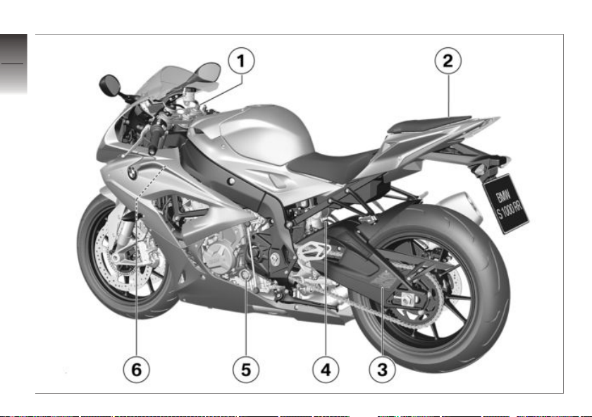
1 Adjuster for spring preload,
front ( 68)
Adjusting front compression damping (red scale)
( 72)
2 Adjusting rear compres-
sion damping (red scale)
( 74)
Adjuster for spring preload,
rear ( 70)
3 Seat lock ( 62)
4 Tire inflation pressure table
Load capacity table
Chain adjustment values
5 Engine oil level indicator
( 159)
6 Connector for optional ac-
cessories ( 139)
2
11
z
Overviews
Page 14
2
12
z
Overviews
Page 15

General view, left side with DDC
with Dynamic Damping Control
OE
(DDC)
1 Adjust spring preload on
front wheel ( 69).
2 Seat lock ( 62)
3 Tire inflation pressure table
Load capacity table
Chain adjustment values
4 Adjuster for spring preload,
rear ( 71)
5 Engine oil level indicator
( 159)
6 Connector for optional ac-
cessories ( 139)
2
13
z
Overviews
Page 16
2
14
z
Overviews
Page 17

General view, right side
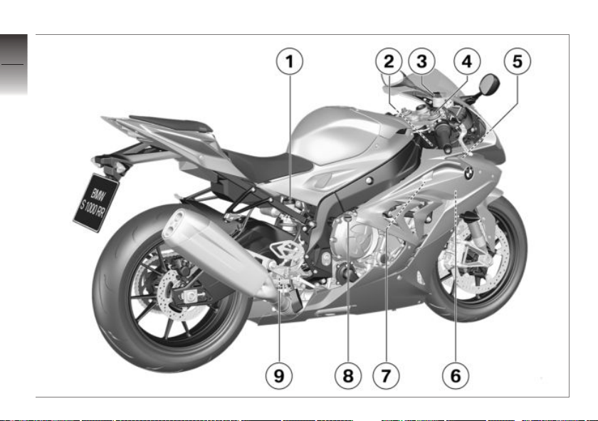
1 Brake-fluid reservoir, rear
( 164)
2 Vehicle identification num-
ber and type plate (on
steering head at right)
3 Brake-fluid reservoir, front
( 163)
4 Adjusting rebound-stage
damping
without Dynamic Damp-
ing Control (DDC)
Rebound-stage damping
on front wheel ( 73).
5 Adjusting the steering
damper ( 67)
6 Checking coolant level
( 166)
7 Connector for optional ac-
cessories ( 138)
8 Oil fill location ( 160)
9 Adjusting rear rebound-
stage damping (yellow
scale) ( 74)
OE
2
15
z
Overviews
Page 18
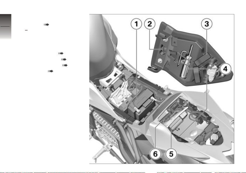
Underneath seat
2
1 Battery ( 185)
16
z
Overviews
with anti-theft alarm sys-
tem (DWA)
Different position of battery
terminals: shifted forward
2 Helmet holder ( 63)
3 Luggage straps ( 64)
4 Onboard tool kit ( 156)
5 Fuse box ( 188)
6 Rider's Manual (US Model)
OE
Page 19
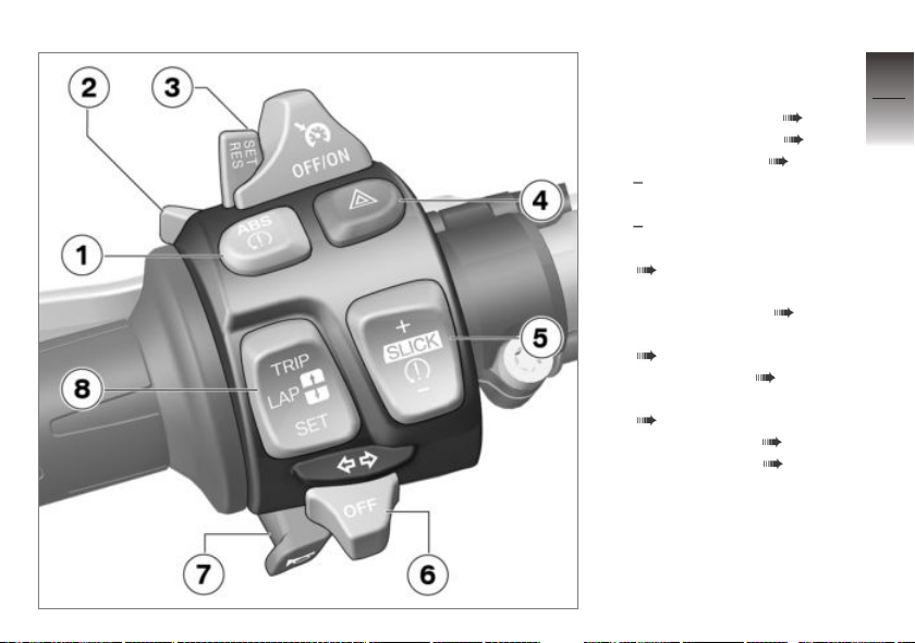
Multifunction switch, left
1 Deactivating ASC ( 51)
Deactivating DTC ( 52)
Deactivate ABS ( 50)
with ABS Pro
or
with ABS Pro
Deactivate ABS Pro
( 50)
2 High-beam headlight and
headlight flasher ( 42)
Start time recording
( 100)
3 Cruise control ( 57)
4 Hazard warning flashers
( 43)
5 Adjusting DTC ( 127)
6 Turn indicators ( 43)
7 Horn
OA
OE
2
17
z
Overviews
Page 20

8 Set clock ( 48)
2
18
z
Overviews
Resetting trip odometer
( 47)
Selecting displays ( 46)
Individualizing lap timer
( 100)
Select submenu ( 113)
Page 21
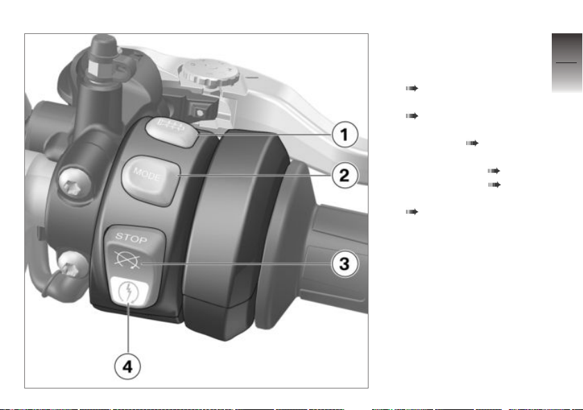
Multifunction switch, right
1 Heated handlebar grips
( 60)
2 Selecting riding mode
( 54)
3 Emergency on/off switch
(kill switch) ( 41)
4 Starter button
Starting engine ( 82)
Launch Control ( 128)
Speed limiter for pit lane
( 130)
2
19
z
Overviews
Page 22
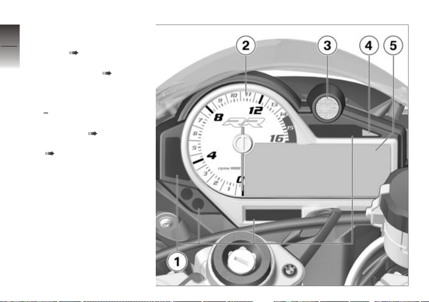
Instrument cluster
2
1 Indicator and warning light
20
z
Overviews
fields ( 22)
2 Tachometer
3 Shiftpoint light ( 87)
4 Photosensor (for adjusting
brightness of instrument
lighting)
with anti-theft alarm system (DWA)
DWA LED ( 48)
5 Multifunction display
( 23)
OE
Page 23

Displays
Indicator and warning lights . . . . . . . . . 22
Multifunction display . . . . . . . . . . . . . . . . 23
ABS Pro display . . . . . . . . . . . . . . . . . . . . 24
Warning lights . . . . . . . . . . . . . . . . . . . . . . 24
3
21
z
Displays
Page 24
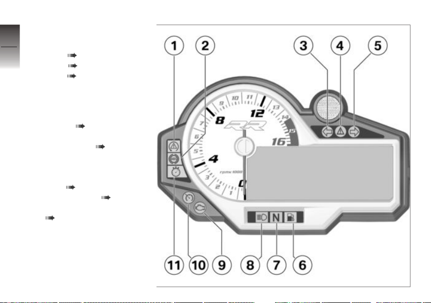
Indicator and warning
3
lights
22
1 ASC ( 33)
DTC ( 33)
2 ABS ( 32)
3 Turn indicator, left
4 Universal warning light,
appears together with
warnings in multifunction
display ( 24)
5 Turn indicator, right
z
Displays
6 Fuel reserve ( 37)
7 Neutral position (idling)
8 High-beam headlight
9 Engine-electronics warning
light ( 29)
10 Cruise control ( 57)
11 Light for fastest lap
( 102)
Page 25
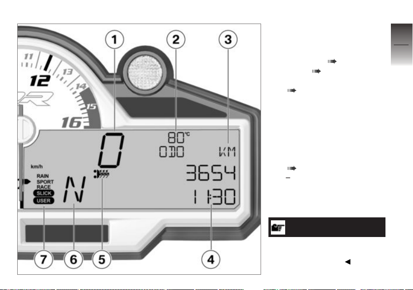
Multifunction display
1 Speedometer
2 Coolant temperature
3 Odometer ( 46)
4 Clock ( 48)
5 Heated handlebar grips
( 60)
6 Gear indicator display, "N"
indicates "neutral".
7 Riding mode
RAIN
SPORT
RACE
Setting riding mode
( 54)
with Pro riding modes
Additional riding modes
SLICK
USER
NOTICE
Refer to Chapter 7 for information regarding the display modes
available for track use.
OE
3
23
z
Displays
Page 26
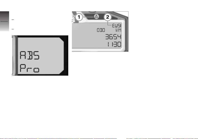
ABS Pro display
3
with ABS Pro
or
24
with ABS Pro
z
Displays
During the Pre-Ride-Check, the
availability of the ABS Pro function is indicated in the multifunction display with ABS Pro.
OA
OE
Warning lights
Display
Warnings are displayed with appropriate warning lights.
Warnings for which no individual
warning light is present are signaled by the universal warning
light 1 which lights up in combination with the appearance of a
warning notice such as 2 in the
multifunction display. The universal warning light shows red
or yellow, depending on the urgency of the warning.
If several warnings are active, all
corresponding warning lights and
warning symbol are displayed;
warnings appear alternately.
You will find an overview of the
potential warnings on the following pages.
Page 27
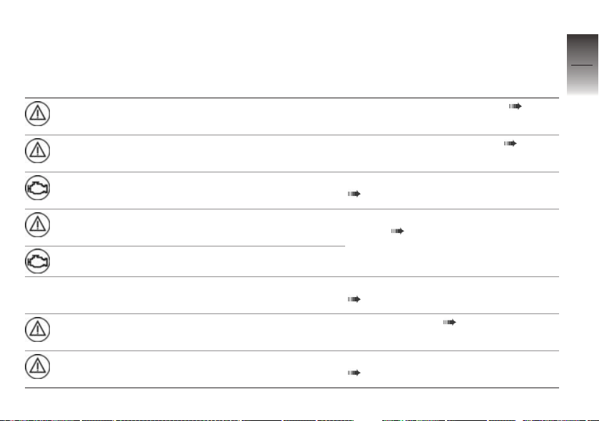
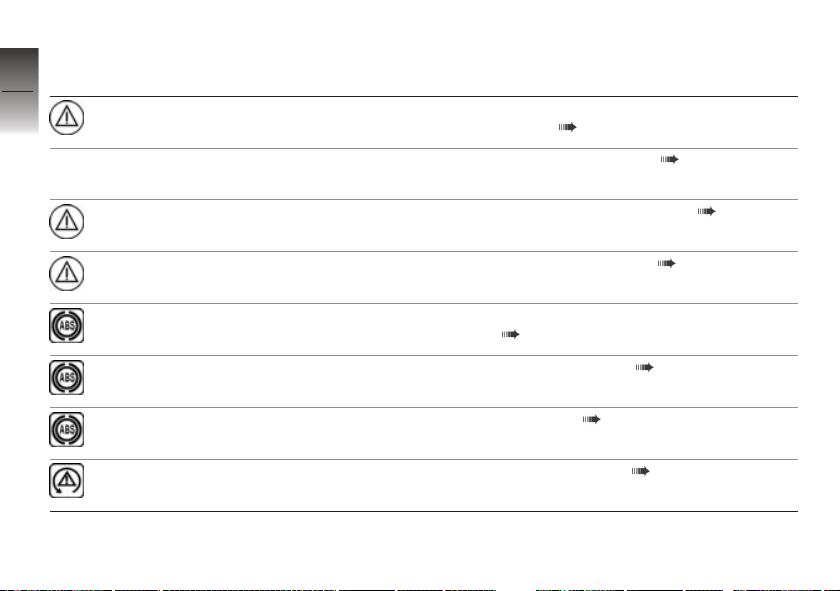
Overview of warning indicators
Indicator and warning
lights
lights up red
Warning symbols in the
display panel
EWS! is displayed
Meaning
Electronic immobilizer is active ( 29)
3
25
flashes red Coolant tempera-
lights up Engine in emergency-operation mode
flashes yellow Severe fault in the engine management
lights up
ture display flashes
LAMP! is indi-
cated
lights up yellow
lights up yellow
LAMPR! is indi-
cated
LAMPF! is indi-
cated
Coolant temperature too high ( 29)
( 29)
system ( 30)
Lights for turn indicators defective
( 30)
Taillight defective ( 31)
Lights for front parking lights defective
( 31)
z
Displays
Page 28
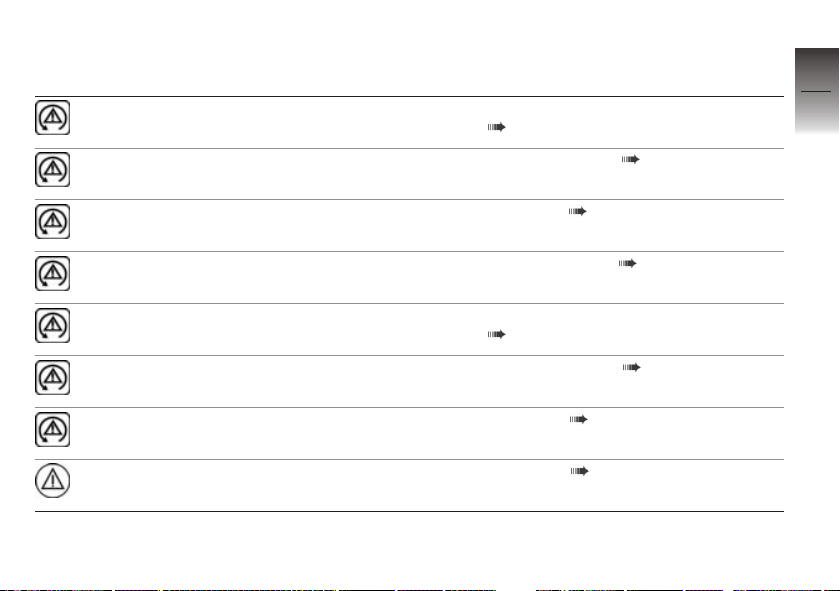
Indicator and warning
3
lights
26
lights up yellow
Warning symbols in the
display panel
LAMPS! is indi-
cated
Meaning
Taillight and lights for parking lights defective ( 31)
Front lights defective ( 31)
z
Displays
lights up yellow
lights up yellow
flashes ABS self-diagnosis not completed
lights up
lights up
flashes rapidly ASC intervention ( 33)
VDS! is shown in
the empty display
VDS! is displayed
Motorcycle has fallen over ( 32)
Fall sensor defective ( 32)
( 32)
ABS switched off ( 32)
ABS error ( 32)
Page 29
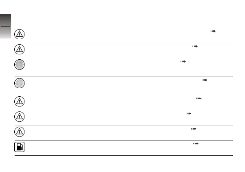
Indicator and warning
lights
flashes slowly ASC self-diagnosis not completed
lights up
Warning symbols in the
display panel
Meaning
( 33)
ASC switched off ( 33)
3
27
lights up
flashes rapidly DTC intervention ( 33)
flashes slowly DTC self-diagnosis not completed
lights up
lights up
lights up yellow
DDC! is displayed
ASC error ( 33)
( 34)
DTC switched off ( 34)
DTC error ( 34)
DDC error ( 35)
z
Displays
Page 30
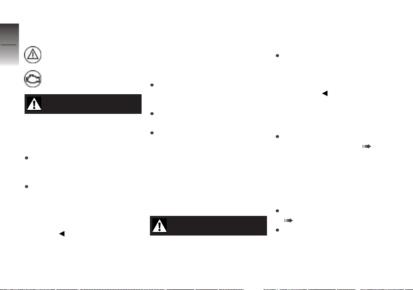
Indicator and warning
3
lights
28
lights up yellow
lights up yellow
Warning symbols in the
display panel
DWALO! is dis-
played
DWA! is displayed
Meaning
DWA battery charge level low ( 35)
DWA battery drained ( 35)
z
Displays
Shiftpoint light
flashes or remains
on continuously
Shiftpoint light
flashes or remains
on continuously
lights up red NO CAN is dis-
lights up yellow NO CODING is
lights up yellow
lights up Fuel down to reserve ( 37)
SPEED! is dis-
played
0L-CON! is indi-
cated
played
displayed
SERVICE! is
indicated
Speed warning ( 36)
Launch Control not ready ( 36)
CAN open/short circuit ( 36)
Encoding missing ( 36)
Service date missed ( 36)
Page 31

Electronic immobilizer is
active
General warning light shows
red.
EWS! is displayed.
Possible cause:
The key being used is not autho-
rized for starting, or communication between the key and engine
electronics is disrupted.
Remove other ignition keys
located on the ignition key.
Use the reserve key.
Have the defective key replaced, preferably by an authorized BMW Motorrad retailer.
Coolant temperature too
high
General warning light
flashes red.
The coolant temperature display
flashes.
ATTENTION
Riding with overheated engine
Engine damage
Be sure to observe the measures listed below.
Possible cause:
The coolant temperature is too
high.
If possible, continue driving
in the part-load range to cool
down the engine.
Should the coolant temperature
frequently be too high, have
the fault rectified as quickly
as possible by an authorized
workshop, preferably an authorized BMW Motorrad retailer.
Engine in emergencyoperation mode
Engine electronics warning
light lights up.
WARNING
Unusual handling when engine is in emergency operating mode
Accident hazard
Adapt riding style: Avoid rapid
acceleration and passing
maneuvers.
Possible cause:
The engine control unit has diag-
nosed a fault. The engine is running in the emergency-operation
mode. In exceptional cases, the
engine stops and can no longer
be started.
Continued driving is possible,
however the accustomed engine output and speed range
may not be available.
Have the malfunction corrected
as soon as possible at an
authorized service facility,
preferably an authorized
BMW Motorrad retailer.
3
29
z
Displays
Page 32
Severe fault in the engine
3
management system
30
z
Displays
General warning light
flashes yellow.
Engine electronics warning
light lights up.
WARNING
Damage to the engine when
it is in the emergency operating mode
Accident hazard
Adapt riding style: Ride slowly,
avoid rapid acceleration and
passing maneuvers.
If possible, have the motorcycle
picked up and the malfunction
source eliminated by a specialized service facility, preferably
an authorized BMW Motorrad
Retailer.
Possible cause:
The engine control unit has di-
agnosed a fault, which can lead
to a severe secondary fault. The
engine is in the emergency-operation mode.
Continued driving is possible, however it is not recommended.
Avoid high load and engine
speed ranges if possible.
Have the malfunction corrected
as soon as possible at an
authorized service facility,
preferably an authorized
BMW Motorrad retailer.
Lights for turn indicators
defective
LAMP! is indicated.
WARNING
Overlooking the motorcycle in traffic due to the light
source on the motorcycle
failing.
Safety risk
Replace defective bulbs as
soon as possible; it is best
always to carry a complete
set of spare bulbs on the
motorcycle.
Possible cause:
Light source for turn indicator
defective
Replacing front and rear turn
indicator light sources ( 180).
Possible cause:
The license-plate carrier is re-
moved and the vehicle's electronic monitoring system detects
the missing turn signals.
Install license-plate carrier
( 133).
Suppress the fault message
in the submenu SETUP
EQUIPMENT with the WARN
LAMP OFF parameter.
Page 33
Taillight defective
General warning light shows
yellow.
LAMPR! is indicated.
Possible cause:
Light source for taillight or brake
light defective.
The diode taillight must be replaced. Please contact a specialist service facility, preferably
an authorized BMW Motorrad
retailer.
Lights for front parking
lights defective
General warning light shows
yellow.
LAMPF! is indicated.
WARNING
Overlooking the motorcycle in traffic due to the light
source on the motorcycle
failing.
Safety risk
Replace defective bulbs as
soon as possible; it is best
always to carry a complete
set of spare bulbs on the
motorcycle.
Possible cause:
Light source for parking light de-
fective
Replacing light source for lefthand parking light ( 178).
Replacing light source of righthand parking light ( 179).
Taillight and lights for
parking lights defective
General warning light shows
yellow.
LAMPS! is indicated. No fault
is displayed when the low-beam
or high-beam headlight fails.
Front lights defective
No fault is displayed when the
low-beam or high-beam headlight
fails.
WARNING
Overlooking the motorcycle in traffic due to the light
source on the motorcycle
failing.
Safety risk
Replace defective bulbs as
soon as possible; it is best
always to carry a complete
set of spare bulbs on the
motorcycle.
Possible cause:
Front light source defective.
Replacing light sources for lowbeam and high-beam headlight
( 176).
3
31
z
Displays
Page 34
Motorcycle has fallen over
3
32
General warning light shows
yellow.
VDS! (Vertical Down Sensor) is
shown in empty display.
Possible cause:
The fall sensor has detected a
fall and switched off the engine.
Position motorcycle upright.
Switch ignition off and then on
z
Displays
again or switch emergency ON/
OFF switch on and then off
again.
Fall sensor defective
General warning light shows
yellow.
VDS! (Vertical Down Sensor) is
displayed.
Possible cause:
A defect was determined in the
fall sensor.
Contact an authorized service
facility, preferably an authorized
BMW Motorrad retailer.
ABS self-diagnosis not
completed
ABS indicator light flashes.
Possible cause:
The ABS system is not available,
as self-diagnosis has not been
completed. To check the wheel
speed sensors, the motorcycle
must be driven a few yards.
Ride off slowly. It must be
noted that the ABS function
is not available until the selfdiagnosis has been completed.
ABS switched off
ABS indicator light lights
up.
Possible cause:
The ABS system has been deac-
tivated by the rider.
Activating ABS ( 51).
ABS error
ABS indicator light lights
up.
Possible cause:
The ABS control unit has de-
tected an error. The ABS function is not available at all or is
restricted.
It is possible to continue riding the motorcycle if you make
allowance for the failed or limited ABS function. You should
also take account of the additional information on situations
that can lead to an ABS fault
( 143).
Have the malfunction corrected
as soon as possible at an
authorized service facility,
Page 35
preferably an authorized
BMW Motorrad retailer.
ASC intervention
ASC indicator and warning
light flashes rapidly.
ASC has detected instability at
the rear wheel and responded by
reducing the torque. The warning light flashes longer than the
ASC intervention lasts. This feature continues to furnish the rider
with visual feedback confirming that the system has initiated
active closed-loop intervention
even after the critical situation
has passed.
ASC self-diagnosis not
completed
ASC indicator and warning
light flashes slowly.
Possible cause:
ASC self-diagnosis routine not completed
The ASC function is not available, as the self-diagnosis
function has not been completed. (To check wheel sensors, motorcycle must reach
a minimum speed with engine running: min 3 mph (min
5 km/h))
Ride off slowly. It must be
noted that the ASC function
is not available until the selfdiagnosis has been completed.
ASC switched off
ASC indicator and warning
light lights up.
Possible cause:
The ASC system has been deac-
tivated by the rider.
Switch on ASC ( 52).
ASC error
ASC indicator and warning
light lights up.
Possible cause:
The ASC control unit has de-
tected an error.
It remains possible to continue
riding. It must be noted that
the ASC function is not available at all or is restricted. You
should also take account of the
additional information on situations that can lead to an ASC
fault ( 146).
Have the malfunction corrected
as soon as possible at an
authorized service facility,
preferably an authorized
BMW Motorrad retailer.
DTC intervention
with Dynamic Traction Control
OE
(DTC)
3
33
z
Displays
Page 36
DTC indicator light flashes
3
34
z
Displays
rapidly.
DTC has detected instability at
the rear wheel and responded by
reducing the torque. The warning light flashes longer than the
DTC intervention lasts. This feature continues to furnish the rider
with visual feedback confirming that the system has initiated
active closed-loop intervention
even after the critical situation
has passed.
DTC self-diagnosis not
completed
with Dynamic Traction Control
OE
(DTC)
DTC indicator light flashes
slowly.
Possible cause:
DTC self-diagnosis not
completed
The DTC function is not available, as the self-diagnosis
function has not been completed. (To check wheel sensors, motorcycle must reach
a minimum speed with engine running: min 3 mph (min
5 km/h))
Ride off slowly. It must be
noted that the DTC function
is not available until the selfdiagnosis has been completed.
DTC switched off
with Dynamic Traction Control
OE
(DTC)
DTC indicator light lights
up.
Possible cause:
The DTC system has been deac-
tivated by the rider.
Switching on DTC ( 53).
DTC error
with Dynamic Traction Control
OE
(DTC)
DTC indicator light lights
up.
Possible cause:
The DTC control unit has de-
tected an error. It must be noted
that the DTC function is not
available at all or is restricted.
It remains possible to continue
riding. You should also take
account of the additional information on situations that can
lead to an DTC fault ( 146).
Have the malfunction corrected
as soon as possible at an
authorized service facility,
Page 37
preferably an authorized
BMW Motorrad retailer.
DDC error
with Dynamic Damping Control
OE
(DDC)
General warning light shows
yellow.
DDC! is displayed.
Possible cause:
The DDC control unit has de-
tected an error.
Have the malfunction corrected
as soon as possible at an
authorized service facility,
preferably an authorized
BMW Motorrad retailer.
Motorcycle damping is in this
condition very firm and riding is
rather uncomfortable - in particular on rough roads.
Possible cause:
The DDC control unit has de-
tected an error.
Have the malfunction corrected
as soon as possible at an
authorized service facility,
preferably an authorized
BMW Motorrad retailer.
Motorcycle damping is in this
condition very firm and riding is
rather uncomfortable - in particular on rough roads.
DWA battery charge level
low
with anti-theft alarm system
OE
(DWA)
General warning light shows
yellow.
DWALO! is displayed.
NOTICE
This fault message is only shown
for a short time immediately following the Pre-Ride-Check.
Possible cause:
The anti-theft alarm battery no
longer has its full capacity. The
operation of the anti-theft alarm
system is only ensured for a limited time with the motorcycle
battery disconnected.
Contact an authorized service
facility, preferably an authorized
BMW Motorrad retailer.
DWA battery drained
with anti-theft alarm system
OE
(DWA)
General warning light shows
yellow.
DWA! is displayed.
3
35
z
Displays
Page 38
3
36
z
Displays
NOTICE
This fault message is only shown
for a short time immediately following the Pre-Ride-Check.
Possible cause:
The anti-theft alarm system bat-
tery is completely discharged.
Operation of the anti-theft alarm
system is no longer ensured
when the motorcycle's battery
is disconnected.
Contact an authorized service
facility, preferably an authorized
BMW Motorrad retailer.
Speed warning
Shiftpoint light flashes or
remains on continuously
according to the selected setting.
SPEED! is displayed.
Possible cause:
The preset maximum speed has
been exceeded.
Reduce speed.
Enter a new maximum speed.
Launch Control not ready
with Pro riding modes
Shiftpoint light lights up or
flashes.
OE
0L-CON! is indicated.
Possible cause:
The number of possible racing
starts with Launch Control has
been exceeded.
Let the clutch cool down.
Race start with Launch Control
( 128).
CAN open/short circuit
General warning light shows
red.
NO CAN (Controller Area Net-
work) is displayed.
Possible cause:
A defect was determined in the
Controller Area Network.
Contact an authorized service
facility, preferably an authorized
BMW Motorrad retailer.
Encoding missing
General warning light shows
yellow.
NO CODING is displayed.
Possible cause:
An encoding error was discov-
ered.
The display goes out after 10
seconds.
Contact an authorized service
facility, preferably an authorized
BMW Motorrad retailer.
Service date missed
General warning light shows
yellow.
SERVICE! is indicated
Page 39
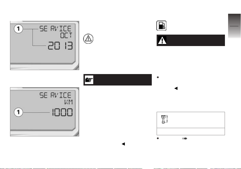
Service display
If service is due within a month,
the service date 1 is displayed.
If service is due within 1000 km
(700 miles), the remaining
distance 1 is displayed and
is counted down in steps of
100 km (100 miles). They are
briefly displayed following the
Pre-Ride-Check.
When a service date
elapses without service, the
general warning light lights up in
yellow, appearing together with
the date and mileage (kilometer)
display. The "Service" message
is displayed continuously.
NOTICE
If the service display appears
more than a month before the
service date, the stored date
must be adjusted in the instrument cluster. This situation can
occur if the battery has been disconnected for a longer time.
Consult a certified workshop,
preferably an authorized
BMW Motorrad retailer, for
setting of the date.
Fuel down to reserve
Fuel-reserve warning light
lights up.
WARNING
Rough engine running or
switching off of the engine
due to a fuel shortage
Accident hazard, damage to catalytic converter
Do not drive to the extent that
the fuel tank is completely
empty.
Possible cause:
At the most, the fuel tank still
contains the reserve fuel quantity.
Fuel reserve
Approx. 1.1 gal (Approx. 4 l)
Refueling ( 91).
3
37
z
Displays
Page 40
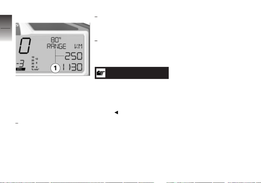
Cruising range
3
38
The RANGE cruising range 1 in-
z
Displays
dicates the distance that can still
be driven with the remaining fuel.
This distance is calculated based
on fuel quantity and average consumption.
RANGE
If the motorcycle is standing
on its side stand, the motorcycle's inclined position will
prevent the fuel level from being registered accurately. For
this reason travel range is only
calculated with the side stand
retracted.
The travel range automatically
appears in the multifunction
display after the fuel reserve
level is reached.
After refueling, the travel range
is recalculated when the fuel
quantity is greater than the fuel
reserve.
NOTICE
The determined range is
an approximate reading.
BMW Motorrad therefore
recommends that you do not
try to use the full range before
refueling.
Page 41

Operation
Steering and ignition lock . . . . . . . . . . . 40
Electronic immobilizer. . . . . . . . . . . . . . . 41
Emergency on/off switch (kill
switch) . . . . . . . . . . . . . . . . . . . . . . . . . . . . . . 41
Lights . . . . . . . . . . . . . . . . . . . . . . . . . . . . . . . 42
Hazard warning flashers. . . . . . . . . . . . . 43
Turn indicators. . . . . . . . . . . . . . . . . . . . . . 43
Multifunction display . . . . . . . . . . . . . . . . 45
Clock . . . . . . . . . . . . . . . . . . . . . . . . . . . . . . . 48
Anti-theft alarm (DWA) . . . . . . . . . . . . . . 48
Antilock Brake System (ABS) . . . . . . . 50
Automatic Stability Control
(ASC) . . . . . . . . . . . . . . . . . . . . . . . . . . . . . . . 51
Dynamic Traction Control (DTC) . . . . 52
Riding mode . . . . . . . . . . . . . . . . . . . . . . . . 53
Cruise control . . . . . . . . . . . . . . . . . . . . . . . 57
Speed warning. . . . . . . . . . . . . . . . . . . . . . 59
Heated handlebar grips . . . . . . . . . . . . . 60
Rider and passenger seats . . . . . . . . . . 61
Helmet holder . . . . . . . . . . . . . . . . . . . . . . 63
Luggage straps .. . . . . . . . . . . . . . . . . . . . 64
4
39
z
Operation
Page 42
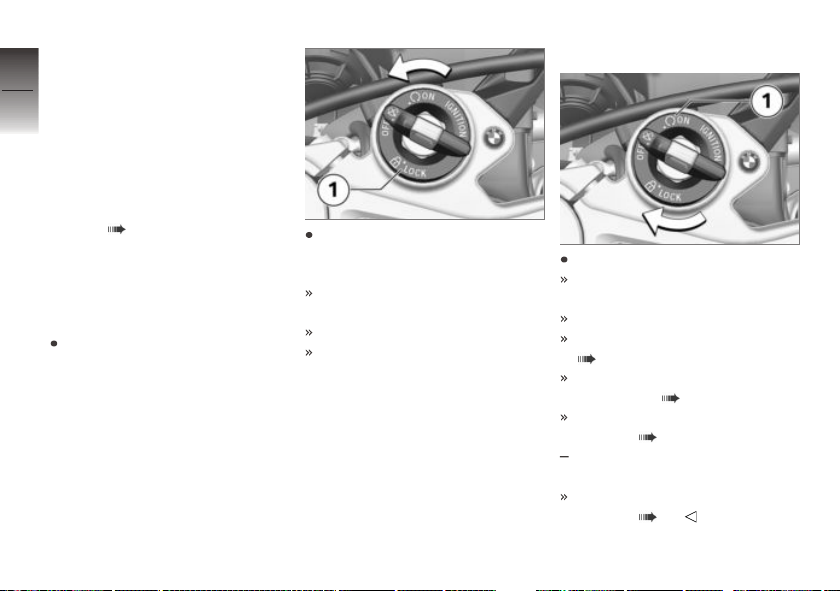
Steering and ignition
4
lock
40
Keys
You are provided with 2 ignition
keys.
Should you lose your keys please
refer to the information regarding the electronic immobilizer
(EWS) ( 41).
A single key fits the steering and
ignition lock, the fuel filler cap
z
Operation
and the seat lock.
Locking handlebars
Turn handlebars to left.
Turn the ignition key to position 1 while moving the handlebars somewhat.
Ignition, lights and all electrical
circuits switched off.
Handlebars locked.
The ignition key can now be
removed.
Switch on ignition
Turn ignition key to position 1.
Parking lights and all function
circuits switched on.
Engine can be started.
Pre-Ride-Check is carried out.
( 83)
ABS self-diagnosis is
performed. ( 84)
ASC self-diagnosis is performed. ( 84)
with Dynamic Traction Control
OE
(DTC)
DTC self-diagnosis is per-
formed. ( 85)
Page 43
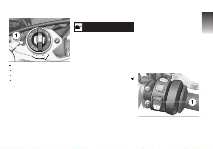
Switch off ignition
Turn ignition key to position 1.
Light switched off.
Handlebars not locked.
The ignition key can now be
removed.
Electronic immobilizer
The motorcycle's electronic circuitry monitors the data stored in
the key through a ring antenna
incorporated in the ignition lock.
The engine management system
does not enable engine starting
until the vehicle key has been
recognized as "authorized" for
your motorcycle.
NOTICE
A further key attached to the
same ring as the ignition key
used to start the engine could
"irritate" the electronics, in which
case the enabling signal for starting is not issued. The EWS!
warning is shown in the multifunction display.
Always store further vehicle keys
separately from the ignition key.
If you lose an ignition key, you
can have it disabled by your
BMW Motorrad partner. When
having a key disabled you should
also bring all of the motorcycle's
remaining keys with you.
The engine can no longer be
started using a disabled vehicle
key; however, a disabled vehicle
key can be enabled again.
Replacement and spare keys are
only available through an authorized BMW Motorrad retailer.
The keys are part of an integrated security system, so the
retailer is under an obligation to
check the legitimacy of all applications for replacement/extra
vehicle keys.
Emergency on/off switch (kill switch)
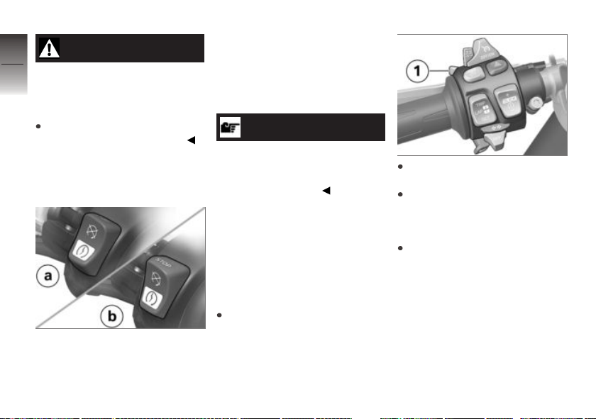
1 Emergency on/off switch
(kill switch)
4
41
z
Operation
Page 44
4
42
z
Operation
WARNING
Operation of the emergency
ON/OFF switch when riding
Danger of falling due to blocking
of rear wheel
Do not operate the emergency
ON/OFF switch when riding.
The engine can be switched
off easily and quickly using the
emergency on/off switch.
a Engine is switched off
b Operating position
Lights
Parking lights
The parking lights come on automatically when the ignition is
switched on.
NOTICE
The parking lights are a strain
on the battery. Do not leave the
ignition switched on longer than
absolutely necessary.
Low-beam headlight
The headlights automatically
come on in their low-beam mode
as soon as you start the engine.
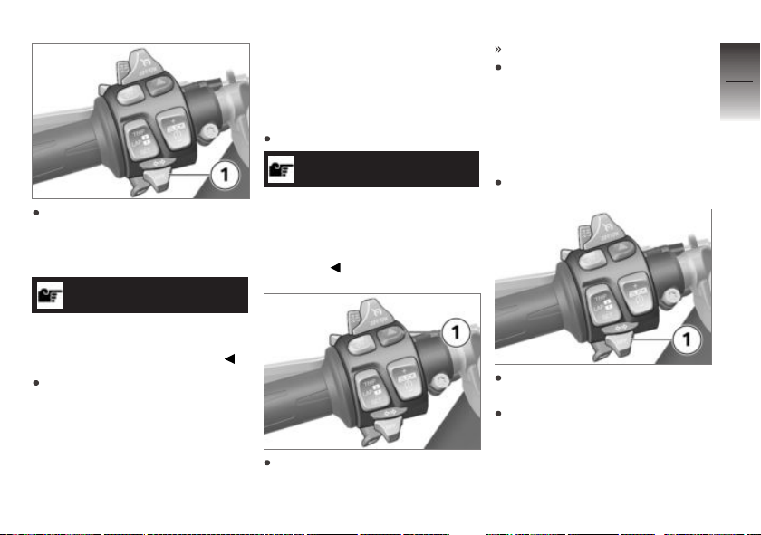
High-beam headlight and
headlight flasher
Start engine.
Press switch 1 toward front to
switch on high-beam headlight.
Pull switch 1 toward rear to
actuate headlight flasher.
Parking lights
Switch off ignition.
Page 45
Immediately after switching off
ignition, push button 1 to left
and hold it until parking lights
come on.
NOTICE
The parking lights can only be
switched on within 10 seconds
after switching off the ignition.
Switch ignition on and then off
again to switch off parking light.
Hazard warning flashers
Switching on hazard
warning flashers
Switch on ignition.
NOTICE
The hazard warning flashers
place a strain on the battery.
Do not use the hazard warning
flashers for longer than absolutely
necessary.
Press button 1 to switch on
hazard warning flashers.
Ignition can be switched off.
Switch on ignition and press
button 1 again to switch off
hazard warning flashers.
Turn indicators
Operating turn indicators
Switch on ignition.
Press button 1 to left to switch
on left-side turn indicators.
Press button 1 to right to
switch on right-side turn
indicators.
4
43
z
Operation
Page 46

Press button 1 into center position to switch off turn indica-
4
tors.
44
NOTICE
The turn indicators automatically switch off when the defined
driving time and distance have
been reached. The defined riding time and distance can be set
by an authorized BMW Motorrad
retailer.
z
Operation
Page 47
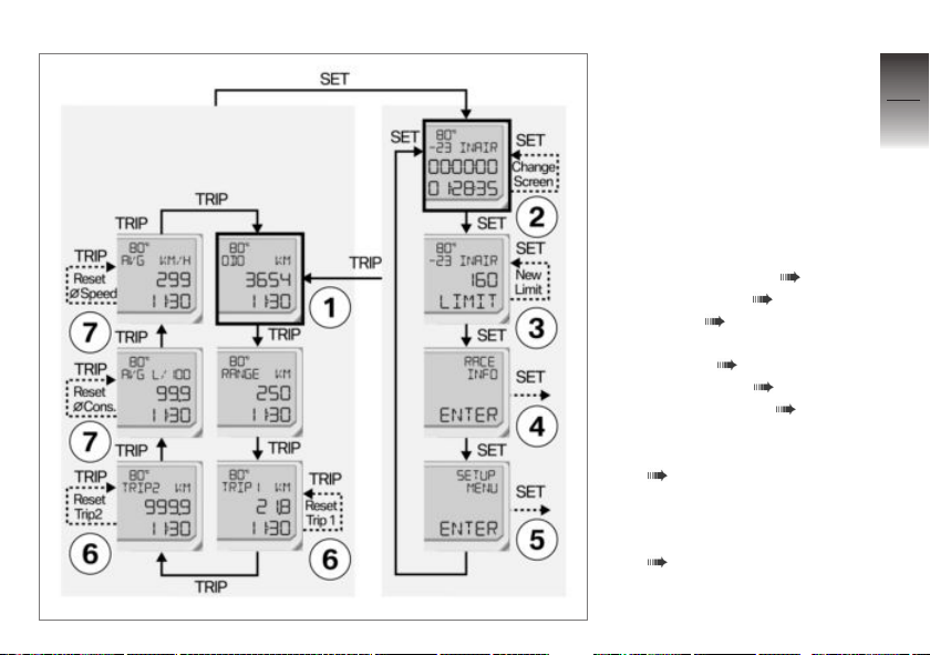
Multifunction display
Overview
— Solid line: briefly press
button.
‑ ‑ Dotted line: press and hold
button.
1 Odometer
Standard display
Select displays in multifunction display ( 46).
2 LAP TIMER ( 99)
3 LIMIT ( 59)
Factory setting for WARN
SPEED ( 118)
4 RACE INFO ( 103)
5 SETUP MENU ( 111)
6 TRIP 1/TRIP 2
Resetting trip odometer
( 47).
7 Average consumption and
average speed
Reset average data
( 47).
4
45
z
Operation
Page 48
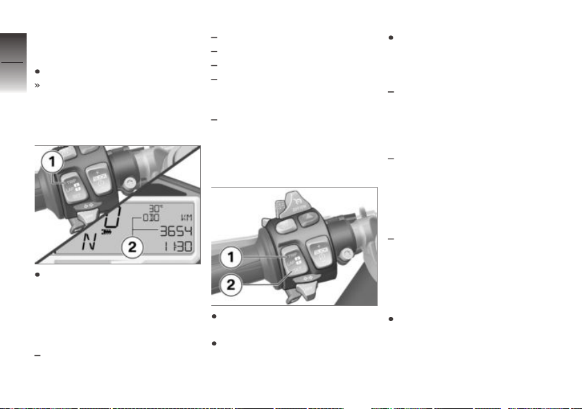
Selecting displays in
4
multifunction display
Switch on ignition.
46
All information required for
operation on public roads is
provided in the multifunction
display.
z
Operation
Press TRIP 1 repeatedly until
desired value is displayed in
area 2.
The following values of the
onboard computer can be
displayed:
Total mileage ODO (standard
display)
Cruising range RANGE
Trip odometer 1 TRIP 1
Trip odometer 2 TRIP 2
Average consumption AVG in
volume per distance or vice
versa
Average speed AVG in distance per hour
Selecting additional
displays
Briefly press SET 2 to obtain
additional displays.
Press TRIP 1 briefly to return
to odometer ODO (standard
display).
Repeatedly press SET 2 until
desired display is selected.
The following displays are available:
LAPTIMER: The lap times
and additional data can be
recorded here and displayed
again in the RACE INFO
menu.
RACE INFO: The stored in-
formation from the LAPTI-
MER can be displayed here.
RACE INFO can only be
opened with the motorcycle
at a standstill.
SETUP MENU: The behavior
of the instrument cluster can
be adjusted to the driver's pref-
erences here. SETUP MENU
can only be opened with the
motorcycle at a standstill.
If LAPTIMER is shown, press
and hold SET 2 to open vari-
ous displays for LAPTIMER.
Page 49
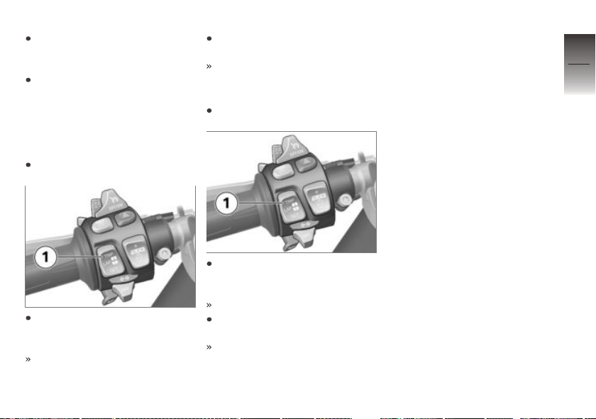
If LIMIT is shown, press and
hold SET 2 to set current driving speed as new limit.
If RACE INFO ENTER or
SETUP MENU ENTER is
shown, press and hold SET 2
to open the respective menu.
Resetting trip odometer
Switch on the ignition.
Briefly press TRIP 1 repeatedly
until desired tripmeter is displayed.
"TRIP 1" or "TRIP 2 " is
indicated.
Press and hold TRIP 1 until
tripmeter has been reset.
Trip mileage = 0.0
Resetting average data
Switch on ignition.
Briefly press TRIP 1 repeatedly
until average value to be reset
is displayed.
AVG is indicated.
Press and hold TRIP 1 until
selected value has been reset.
Average value = 0.0
4
47
z
Operation
Page 50
Clock
4
Setting clock
48
Switch on ignition.
z
Operation
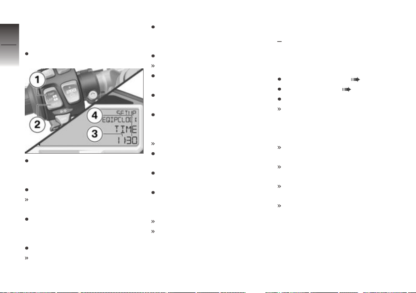
Briefly press SET 2 repeatedly
until SETUP MENU ENTER
is displayed.
Press and hold SET 2.
The SETUP MENU is
opened.
Briefly press SET 2 repeatedly
until SETUP EQUIPMENT
ENTER is displayed.
Press and hold SET 2.
The SETUP EQUIPMENT
menu is opened.
Briefly press SET 2 repeatedly
until SETUP EQIP:CLOCK
TIME is displayed.
Press and hold SET 2.
Minutes 4 flash.
Briefly press TRIP 1 to increase minutes.
Briefly press TRIP 2 to decrease minutes.
When the minutes have been
set as desired, press and hold
SET 2.
Hours 3 flash.
Briefly press TRIP 1 to increase hours.
Briefly press TRIP 2 to decrease hours.
When the hours have been
set as desired, press and hold
SET 2.
The hours no longer flash.
The clock is now set.
Anti-theft alarm (DWA)
with anti-theft alarm system
OE
(DWA)
Activation
Switch on ignition ( 40).
DWA Adjusting ( 49).
Switch off ignition.
If the DWA is activated, the
DWA is automatically activated
after the ignition is switched
off.
Anti-theft alarm (DWA) is active
after approx. 30 seconds.
Turn indicators are illuminated
twice.
Confirmation tone sounds
twice (if programmed).
DWA is armed.
Page 51
Alarm signal
The DWA alarm can be set off
by:
Motion sensor
Switching on ignition with an
unauthorized motorcycle key.
Disconnecting the DWA from
the motorcycle battery (DWA
battery takes over the power
supply – alarm sound only, hazard warning lights do not flash).
If the DWA battery is discharged
all functions remain operational;
the only difference is that the
alarm cannot be set off if the
system is disconnected from the
motorcycle battery.
An alarm lasts for approximately
26 seconds. During the alarm,
an alarm tone sounds and the
turn indicators flash. The alarm
tone type can be adjusted by
an authorized BMW Motorrad
retailer.
If an alarm was triggered while
the motorcycle was unattended,
the rider is notified accordingly
by an alarm tone sounding once
when the ignition is switched on.
The DWA (alarm system) LED
then indicates the reason for the
alarm signal for one minute.
Light signals on DWA LED:
1 flash: Motion sensor 1
2 flashes: Motion sensor 2
3 flashes: Ignition switched on
with unauthorized motorcycle
key
4 flashes: DWA disconnected
from motorcycle battery
5 flashes: Motion sensor 3
Deactivation
Set emergency on/off switch
(kill switch) to normal operating
position.
Switch on the ignition.
Turn indicators light up once.
Confirmation tone sounds once
(if programmed).
DWA is now switched off.
DWA Adjusting
Switch on ignition ( 40).
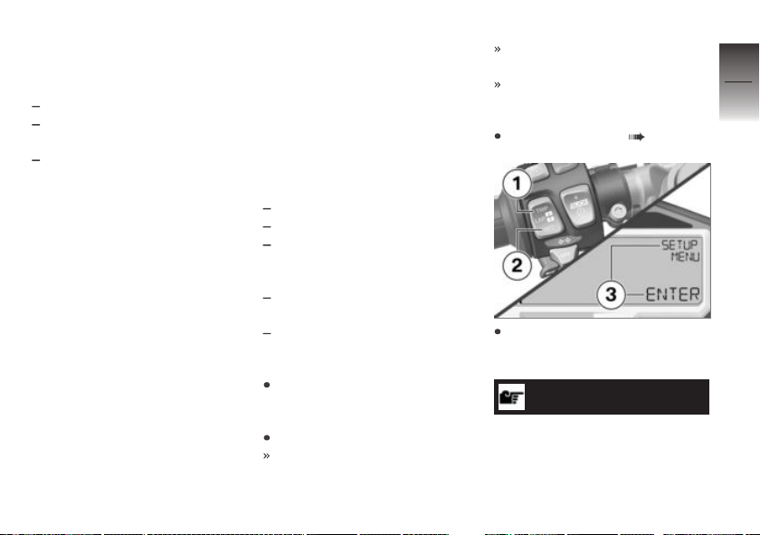
Briefly press SET 2 repeatedly until SETUP MENU EN-
TER 3 is displayed.
NOTICE
If the display has been scrolled
too far, briefly press SET 2 repeatedly until the menu returns
4
49
z
Operation
Page 52
to the start and finally to the desired display.
4
Press and hold SET 2 to open
50
the menu.
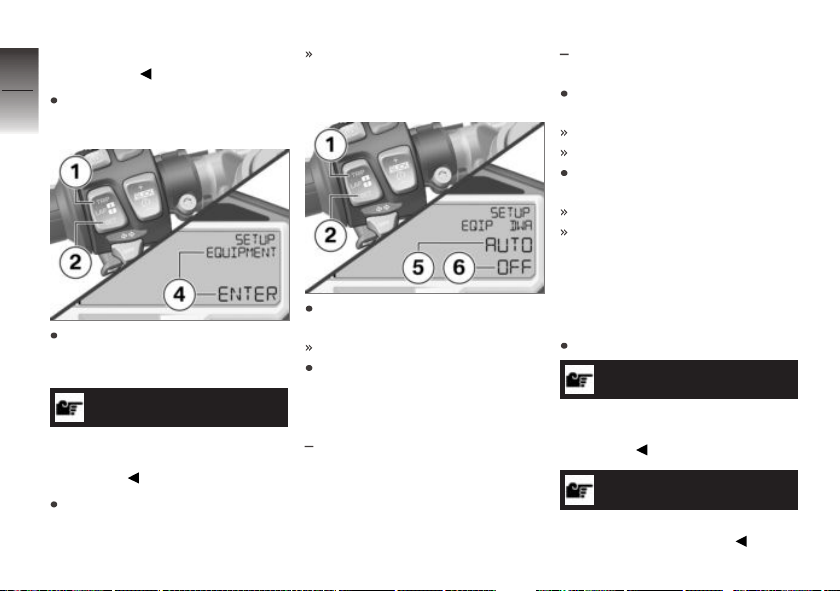
Parameter DWA AUTO 5 and
its current value 6 are displayed.
DWA AUTO OFF: DWA is
deactivated.
Press and hold SET 2 to save
the set value.
The value 6 no longer flashes.
The clock is now set.
Press and hold TRIP 1 to can-
cel the adjustment procedure.
Adjustment canceled.
ODO is indicated
z
Operation
Briefly press SET 2 repeatedly
until SETUP EQUIPMENT
ENTER 4 is displayed.
NOTICE
If the display has been scrolled
too far, briefly press TRIP 1 to
scroll back.
Press and hold SET 2 to open
the menu.
Press and hold SET 2 to edit
the set value 6.
The value 6 flashes.
Briefly press TRIP 1 or SET 2
to change the value.
The following settings are available:
DWA AUTO ON: DWA is acti-
vated respectively is activated
automatically when the ignition
is switched off.
Antilock Brake System (ABS)
Deactivate ABS
Switch on the ignition.
NOTICE
ABS Pro is operated in the
same way as BMW Motorrad
Race ABS.
NOTICE
The ABS function can also be
deactivated while driving.
Page 53
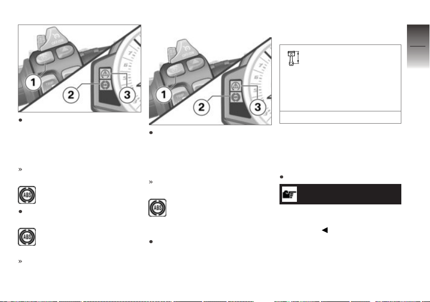
Press and hold the 1 button
until first the ASC/DTC indicator light 3 and then the ABS
indicator and warning light 2
change their display behavior.
The ASC/DTC setting remains
unchanged.
ABS indicator light lights
up.
Release button 1 within two
seconds.
ABS indicator light continues to be lit up.
ABS is deactivated.
Activating ABS
Press and hold the 1 button
until first the ASC/DTC indicator light 3 and then the ABS
indicator and warning light 2
change their display behavior.
The ASC/DTC setting remains
unchanged.
ABS indicator light goes
out, and starts to flash if
self-diagnosis has not been completed.
If the coding plug for the
SLICK/USER riding mode is
not installed, the ignition can
also be switched off and then
on again as an alternative.
If the ABS indicator light
lights up after switching the ignition off and on and
then continuing to ride above
the minimum speed, an ABS
fault has occurred.
min 6 mph (min 10 km/h)
Automatic Stability Control (ASC)
Deactivating ASC
Switch on the ignition.
NOTICE
The Automatic Stability Control
(ASC) can also be deactivated
while riding.
4
51
z
Operation
Page 54
4
52
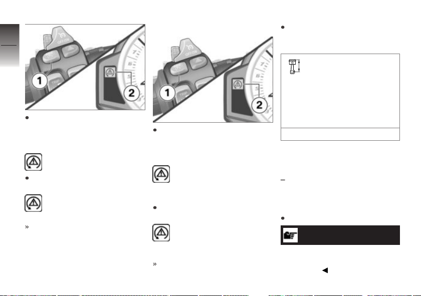
Press and hold the 1 button
until the ASC-indicator and
warning light 2 changes its
z
Operation
display behavior.
ASC indicator and warning
light starts to light up.
Release button 1 within two
seconds.
ASC indicator and warning
light continues to be lit up.
ASC is deactivated.
Switch on ASC
Press and hold the 1 button
until the ASC-indicator and
warning light 2 changes its
display behavior.
ASC indicator and warning
light goes out, and starts
to flash if self-diagnosis has not
been completed.
Release button 1 within two
seconds.
ASC indicator and warning
light remains off or continues to flash.
ASC activated.
As an alternative, the ignition
can also be switched off and
then on again.
If the ASC indicator and
warning light lights up
after switching the ignition off
and on and then continuing to
ride at the following minimum
speed, an ASC fault has occurred.
min 6 mph (min 10 km/h)
Dynamic Traction Control (DTC)
with Dynamic Traction Control
OE
(DTC)
Deactivating DTC
Switch on the ignition.
NOTICE
The Dynamic Traction Control
(DTC) can also be deactivated
while riding.
Page 55
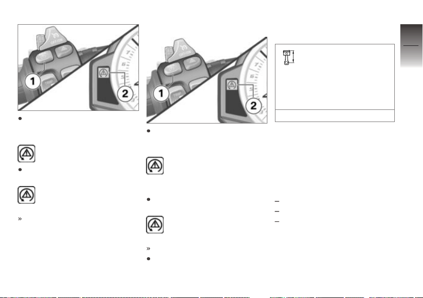
Press and hold the 1 button
until the DTC-indicator light 2
changes its display behavior.
DTC indicator light starts to
light up.
Release button 1 within two
seconds.
DTC indicator light continues to be lit up.
DTC is deactivated.
Switching on DTC
Press and hold the 1 button
until the DTC-indicator light 2
changes its display behavior.
DTC indicator light goes
out, and if self-diagnosis
has not been completed, it begins to flash.
Release button 1 within two
seconds.
DTC indicator light remains
off or continues to flash.
DTC activated.
If the coding plug is not installed, the ignition can also be
switched off and then on again
as an alternative.
If the DTC indicator light
lights up after switching the ignition off and on and
then continuing to ride at the
following minimum speed, a
DTC fault has occurred.
min 6 mph (min 10 km/h)
Riding mode
Use of the riding modes
BMW Motorrad has developed 5
riding scenarios for your motorcycle from which you can select
the one matching your situation:
Riding on wet roads.
Sporty riding on dry roads.
Riding on racetracks with series tires.
4
53
z
Operation
Page 56
with Dynamic Traction Control
OE
(DTC)
4
Riding on racetracks with se-
54
ries tires.
Riding on racetracks with racing tires while taking settings
by driver into account.
For each of those 5 scenarios,
the optimum balance between
engine torque, throttle response,
ABS control and ASC or DTC
z
Operation
control for the situation concerned is provided.
with Dynamic Damping Control
OE
(DDC)
The suspension settings is adjusted to the selected scenario
as well.
Setting riding mode
Switch on ignition ( 40).
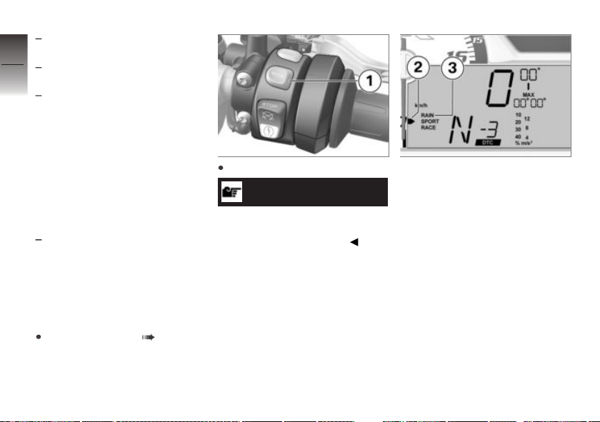
Press button 1.
NOTICE
Details on the selectable driving
modes are provided in the chapter "Technology in Detail".
The selection arrow 2 and the
selectable riding modes 3 are
displayed. The last active riding
mode flashes.
Page 57
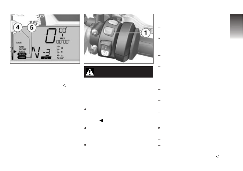
with Pro riding modes
With the coding plug installed,
the riding modes SLICK 4 and
OE
USER 5 are also offered.
WARNING
Activating the SLICK mode
outside the racetrack or
without racing tires
Accident hazard caused by low
tire grip
Only activate SLICK mode on
racetracks and with racing tires
fitted.
Press 1 button repeatedly until
selection arrow 2 points to desired riding mode.
When the motorcycle is stationary, the selected riding
mode is activated after approx.
2 seconds.
Selection arrow 2 and inactive
riding modes are hidden.
The new riding mode is activated during operation under
the following conditions:
Throttle grip is in neutral position.
Brake levers are not being op-
erated.
The following riding modes can
be selected:
RAIN: When riding on wet
roads.
SPORT: For sporty riding on
dry roads.
RACE: For riding on racetracks
with series tires.
The following riding modes can
also be selected:
with Pro riding modes
OE
SLICK: For riding on race-
tracks with racing tires (only
with coding plug installed).
4
55
z
Operation
Page 58
with Pro riding modes
USER: Riders can combine
4
the settings from all available
56
functions (ENGINE, ABS, DTC
and DDC) in any way they
wish, according to their preferences or current prevailing
conditions. A technical understanding of the settings
is assumed (only with coding
plug installed, see the chapter
"Technology in detail").
z
Operation
The riding mode selected and
its associated engine-characteristic, ABS, DTC and DDC
settings are retained even after
the ignition has been switched
off.
When selecting SLICK riding mode: Observe restricted
ABS control intervention at rear
wheel (see chapter "Technology in detail").
The values set in the SETUP
USER-MODE are not contin-
OE
ually displayed, but instead only
after the following events for a
limited time:
After every pre-ride check with
USER riding mode active.
After changing to USER riding
mode.
When 1 (MODE) button is
pressed in USER riding mode
without changing riding mode.
Install coding plug
with Pro riding modes
WARNING
Increased engine performance in all riding modes
by inserting the coding plug
on motorcycles with power
reduction
Accident hazard
Familiarize yourself with the
more performance-oriented
response.
OE
Do not use the encoding plug
on public roads.
Switch off ignition ( 41).
Removing rider`s seat ( 63).
ATTENTION
Penetration of dirt and mois-
ture in the open connector
Malfunctions
After removing the encoding
plug, refit the cover cap.
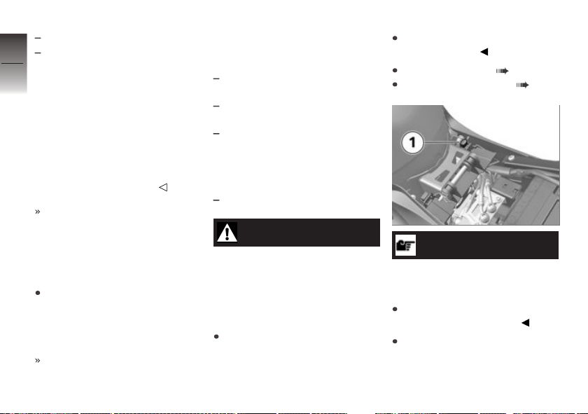
Remove cap 1 of connector.
Page 59
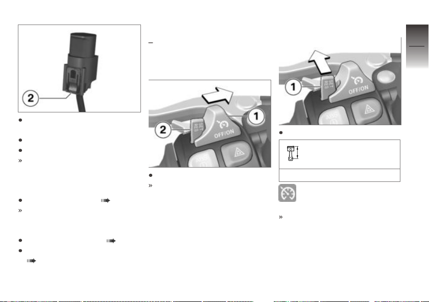
To do so, press in locking device 2 and pull off cap.
Insert coding plug.
Switch on the ignition.
For safety reasons, after the
coding plug is connected, the
RAIN riding mode is automat-
ically activated.
Setting riding mode ( 54).
The set riding mode remains
active even after the ignition is
switched off.
Installing driver's seat ( 63).
Remove license-plate carrier
( 132).
Cruise control
with cruise control
Switching on cruise
control
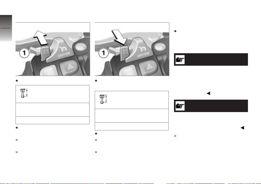
Push switch 1 to right.
Button 2 is unlocked.
OE
Storing speed
Briefly press button 1 forward.
Adjustment range for
cruise control
19...130 mph (30...210 km/h)
Indicator light for cruise-
control system lights up.
The motorcycle maintains your
current cruising speed and the
setting is saved.
4
57
z
Operation
Page 60
Acceleration
4
58
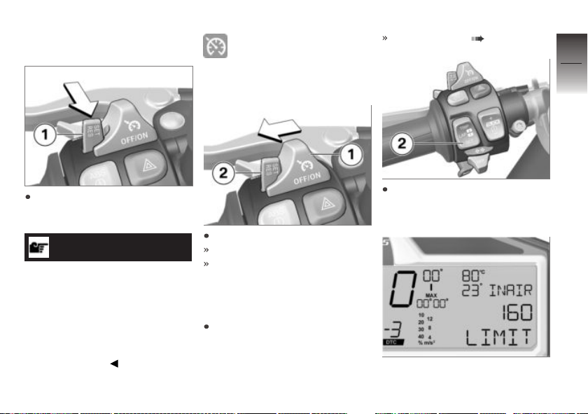
Briefly press button 1 forward.
z
Operation
Increase speed
Speed is increased each time
button is pressed.
1 mph (1 km/h)
Press button 1 forward and
hold.
The motorcycle accelerates
steplessly.
If the button 1 is no longer
pressed, the speed achieved
is maintained and saved.
Decreasing speed
Briefly press button 1 backward.
Decreasing the speed
Speed is decreased each time
button is pressed.
1 mph (1 km/h)
Press button 1 back and hold.
The motorcycle decelerates
steplessly.
If the button 1 is no longer
pressed, the speed achieved
is maintained and saved.
Deactivating cruise
control
Actuate brakes, clutch or throttle grip (take back throttle beyond back position) to deactivate cruise-control system.
NOTICE
When changing gear using the
Pro Gear-shift Assistance function, the cruise-control system
is automatically deactivated for
safety reasons.
NOTICE
With ASC and DTC interventions,
the cruise control is automatically
deactivated for safety reasons.
Cruise control indicator light
goes out.
Page 61
Resuming former cruising
speed
Indicator light for cruisecontrol system lights up.
Switching off cruise
control
Speed warning ( 118)
4
59
Briefly push button 1 back to
return to the speed saved beforehand.
NOTICE
Opening the throttle does not
deactivate the cruise-control system. If you release the throttle
grip, the motorcycle will decelerate only to the cruising speed
saved in memory, even though
you might have intended slowing
to a lower speed.
Push switch 1 to left.
The system is deactivated.
Button 2 is locked.
Speed warning
Setting speed warning
If necessary, activate speed
warning in SETUP EQUIP-
MENT submenu. See chapter
"On the racetrack":
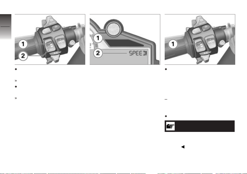
Briefly press SET 2 repeatedly until LIMIT is shown in
display.
Either the current preset speed
or OFF appears in the display.
z
Operation
Page 62
4
60
To set current speed as new
limit: press and hold SET 2.
The current speed is displayed
z
Operation
To increase set speed: briefly
press TRIP 1.
Each time you press the button
the speed increases by 5 km/h.
When the preset speed is exceeded, the shiftpoint light 1 responds by lighting up or flashing
at the preset frequency and the
warning 2 appears in the display.
To deactivate the speed warning: Press and hold TRIP 1 until OFF appears in the display.
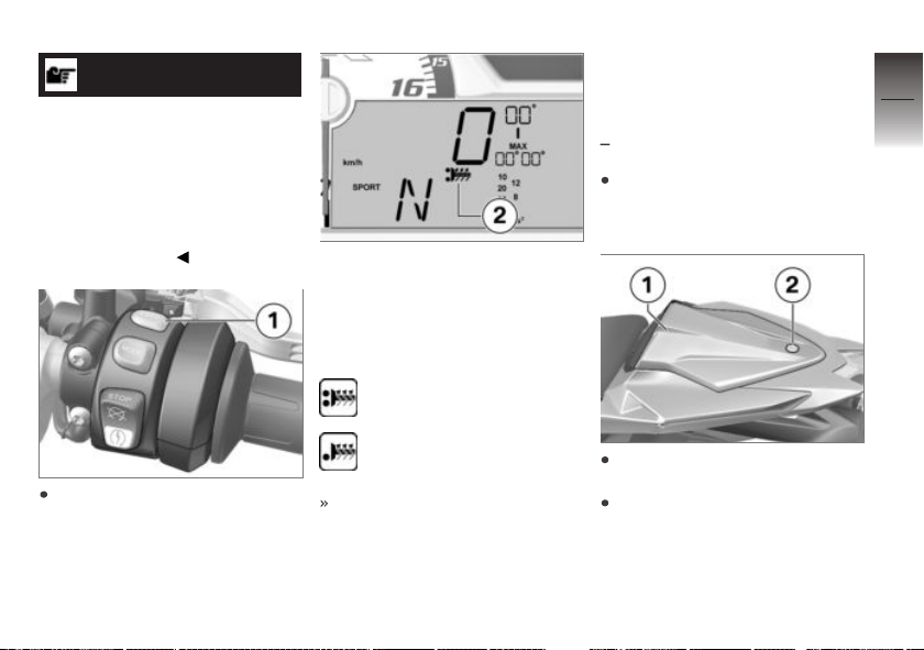
Heated handlebar grips
with heated handlebar grips
Operating heated grips
Start engine.
NOTICE
The heated grips option can only
be activated when the engine is
running.
OE
Page 63
NOTICE
The increase in power
consumption caused by the
heated grips can drain the
battery if you are riding at low
engine speeds. If the battery is
inadequately charged, the heated
grips are switched off to ensure
starting capability.
Press button 1 repeatedly until
desired heating level is displayed in multifunction display.
The handlebar grips can be
heated at two different levels.
The second stage 2 is intended
for rapid heating of the grips.
Once they are warm you should
switch back to the first stage.
Second step: 100 % heating capacity
First step: 50 % heating
capacity
If no further changes are made
the selected heating level is
adopted as the setting.
Rider and passenger seats
Removing hump cover
with passenger seat cover
Park motorcycle, ensuring that
support surface is firm and
level.
Unlock lock 2 in hump cover 1
using ignition key.
Lift hump cover at rear, then
remove by pulling back and
upward.
OE
4
61
z
Operation
Page 64
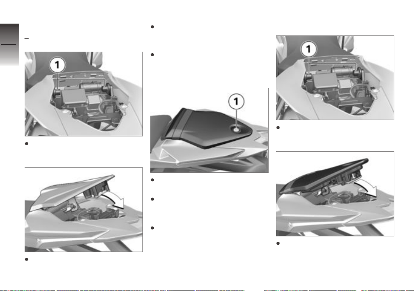
Installing hump cover
4
with passenger seat cover
62
z
Operation
Mount hump cover in
mounts 1 on left and right.
Press the hump cover forward
slightly then fold it down.
OE
Lock lock with ignition key.
Removing passenger seat
Park motorcycle, ensuring that
support surface is firm and
level.
Unlock seat lock 1 with vehicle
ignition key.
Lift passenger seat at rear,
then remove by pulling back
and upward.
Remove ignition key and lay
passenger seat on a clean surface with upholstered side on
bottom.
Install the passenger seat
Mount passenger seat in
mounts 1 on left and right.
Press the rear seat forward
slightly then fold it down.
Page 65
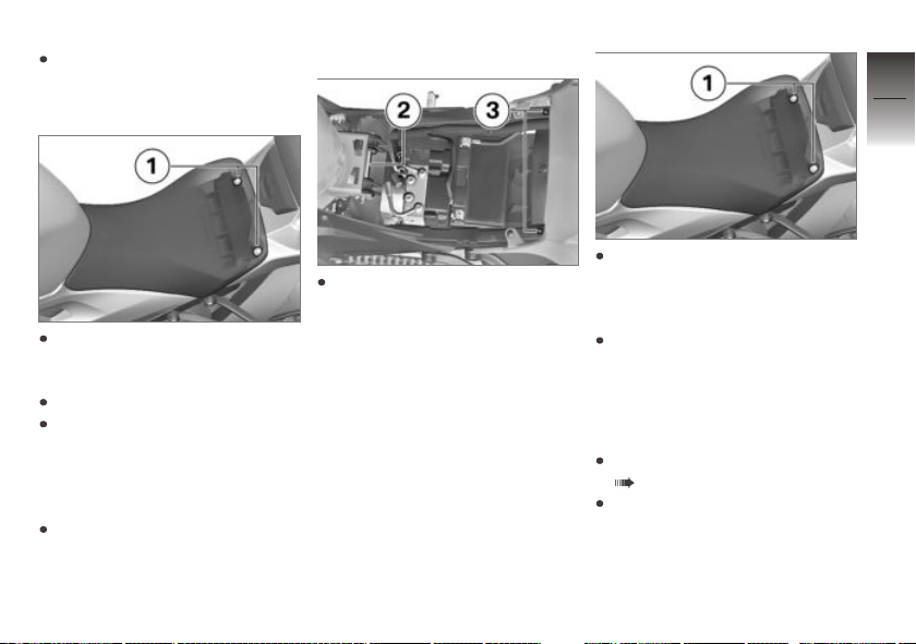
Lock seat lock with ignition
key.
Removing rider`s seat
Press cover of driver's seat
above screws 1 forward somewhat and hold in place.
Remove screws.
Push the rider`s seat forward,
lift it at the rear and remove it.
When doing so, make sure that
the paneling is not damaged by
the screws.
Lay the rider`s seat on a clean
surface with the upholstered
side down.
Installing driver's seat
Mount rider`s seat in mount 2,
then position over screw sockets 3. When doing so, make
sure that the paneling is not
damaged by the screws.
Press cover of driver's seat
over screw sockets toward
front somewhat and hold in
place.
Install screws 1.
Helmet holder
Securing helmet on
motorcycle
Remove passenger seat
( 62).
Turn over passenger seat.
4
63
z
Operation
Page 66
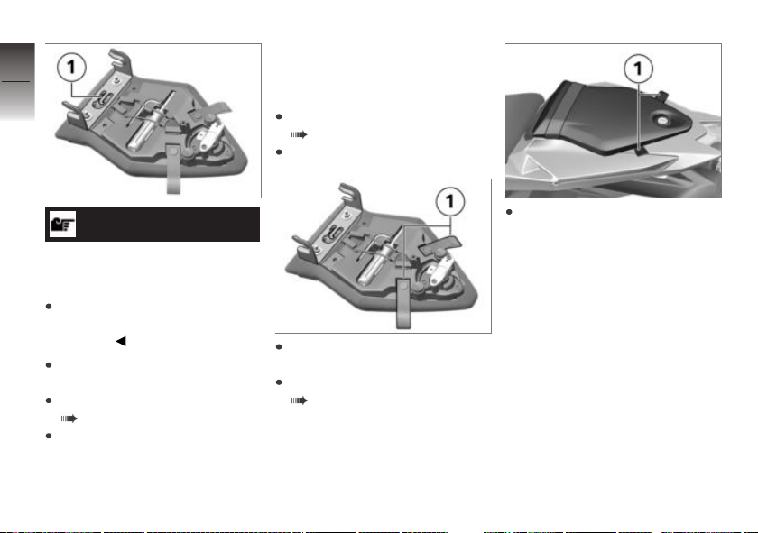
4
64
Luggage straps
Securing luggage on
motorcycle
Remove passenger seat
( 62).
Turn over passenger seat.
ATTENTION
z
Operation
Incorrect positioning of the
helmet lock
Fairing scratched
When hooking on the helmet,
watch the position of the helmet lock.
Secure helmet on helmet
holder 1 using a steel cable.
Install the passenger seat
( 62).
Set down helmet on driver's
seat.
Use luggage loops 1, e.g. in
conjunction with passenger
footrests, to lash luggage onto
passenger seat. When doing
so, make sure that the rear trim
is not damaged.
Remove luggage loops 1 from
holders and lay to outside.
Install the passenger seat
( 62).
Page 67

Setting
Mirrors . . . . . . . . . . . . . . . . . . . . . . . . . . . . . . 66
Headlight . . . . . . . . . . . . . . . . . . . . . . . . . . . 66
Brakes . . . . . . . . . . . . . . . . . . . . . . . . . . . . . . 66
Steering . . . . . . . . . . . . . . . . . . . . . . . . . . . . 67
Spring preload . . . . . . . . . . . . . . . . . . . . . . 67
Damping . . . . . . . . . . . . . . . . . . . . . . . . . . . . 72
DDC . . . . . . . . . . . . . . . . . . . . . . . . . . . . . . . . 75
5
65
z
Setting
Page 68
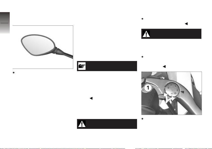
Mirrors
5
Adjusting mirrors
66
z
Setting
Move mirror to the desired position by turning it.
Headlight
Adjusting headlight for
RHD/LHD traffic
This motorcycle's headlight features a symmetrical low beam.
No special adjustments or procedures are required prior to operating the motorcycle in a country where traffic travels on the
side of the road opposite to that
of your home country (left-hand
drive to right-hand drive or vice
versa).
Headlight range and
spring preload
The headlight range generally
remains constant due to the adjustment of the spring preload to
the loading state.
NOTICE
If there are doubts as to the correct headlight range, have the
adjustment checked by a specialized workshop, preferably by
an authorized BMW Motorrad
retailer.
Brakes
Adjusting brake lever
WARNING
Modified position of the
brake-fluid reservoir.
Air in the brake system.
Do not twist the handlebar fitting or the handlebars.
WARNING
Adjusting the brake lever
while driving.
Accident hazard
Only adjust the brake lever
when the motorcycle is
stationary.
Rotate the adjusting screw 1
into the desired position by
applying gentle pressure from
the rear.
Page 69
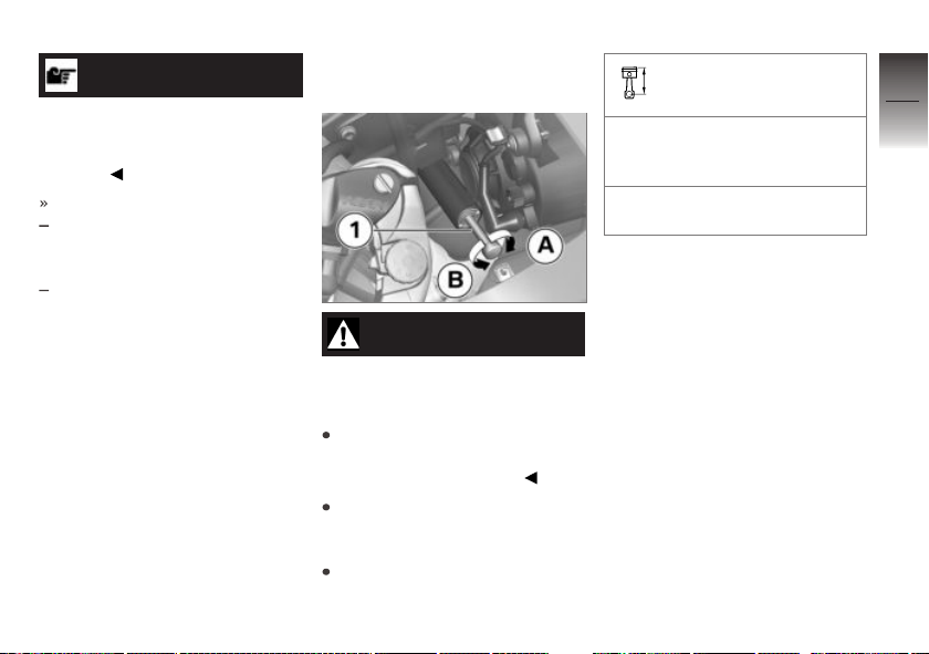
NOTICE
The adjusting screw can be
turned more easily if you push
the brake lever forward when
doing so.
Adjustment options:
From position 1: Largest distance between handlebar grip
and brake lever
to position 6: Smallest distance
between handlebar grip and
brake lever
Steering
Adjusting steering damper
WARNING
Adjusting the steering
damper while riding.
Accident hazard
Never adjust the steering
damper except while the
motorcycle is stationary.
Turn adjustment screw 1 in direction A to increase damping
force.
Turn the screw 1 in direction B
to reduce damping force.
Basic steering damper
adjustment setting
Opens at 8 clicks (starting at
fully closed) (Highway operation)
Opens at 5 clicks (starting at
fully closed) (Racetrack)
Spring preload
Setting
The spring preload on the front
wheel must be adapted to the
weight of the rider. Higher
weight requires a higher spring
preload, lower weight requires a
lower spring preload.
It is essential to set the spring
preload to suit the load carried by
the motorcycle. Increase spring
preload when the vehicle is heavily loaded and reduce spring
preload accordingly when the
vehicle is lightly loaded.
5
67
z
Setting
Page 70
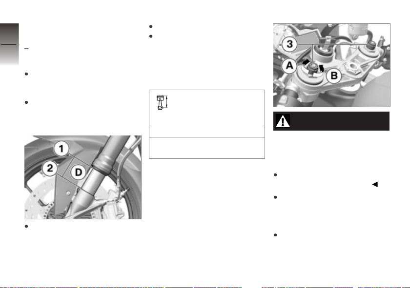
Adjusting spring preload
5
on front wheel
without Dynamic Damping
68
Control (DDC)
Park motorcycle, ensuring that
support surface is firm and
level.
Make sure there is no load on
the motorcycle, removing any
cargo or luggage.
z
Setting
Hold motorcycle in a vertical position and measure distance D between lower edge 1
of immersion tube and front
axle 2.
OE
Load motorcycle with driver.
With the assistance of a helper,
measure distance D between
points 1 and 2 again and calculate difference (spring deflection) between the measured
values.
Adjustment of spring
preload dependent on
loading
Compressing front wheel
0.4...0.6 in (10...15 mm) (With
rider 187 lbs (85 kg))
WARNING
Uncoordinated settings of
spring preload and spring
strut damping.
Poorer handling.
Adjust damping characteristic
to changed spring preload.
To decrease spring deflection
(increase spring preload), turn
adjusting screws 3 with tool of
onboard tool kit in direction A.
To increase spring deflection
(decrease spring preload), turn
adjusting screws 3 with tool of
onboard tool kit in direction B.
Page 71
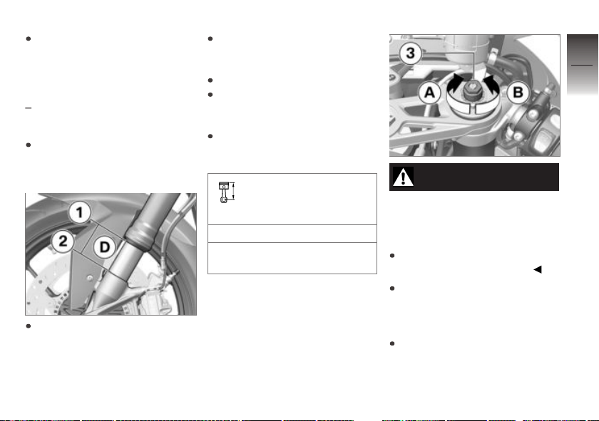
Ensure that settings on left and
right sides are identical.
Adjusting spring preload
on front wheel
with Dynamic Damping Control
OE
(DDC)
Park motorcycle, ensuring that
support surface is firm and
level.
Hold motorcycle in vertical position, preferably with help of
a second person (not the side
stand).
Measure distance D between
lower edge 1 of immersion
tube and front axle 2.
Load motorcycle with driver.
Measure distance D between
points 1 and 2 with assistance
of a 2nd person.
Calculate spring deflection as
difference between measured
values.
Adjustment of spring
preload dependent on
loading
Compressing front wheel
0.4...0.6 in (10...15 mm) (With
rider 187 lbs (85 kg))
WARNING
Uncoordinated settings of
spring preload and spring
strut damping.
Poorer handling.
Adjust damping characteristic
to changed spring preload.
To decrease spring deflection
(increase spring preload), turn
adjusting screw 3 with tool of
onboard tool kit in direction A.
To increase spring deflection
(decrease spring preload), turn
adjusting screw 3 with tool of
onboard tool kit in direction B.
5
69
z
Setting
Page 72
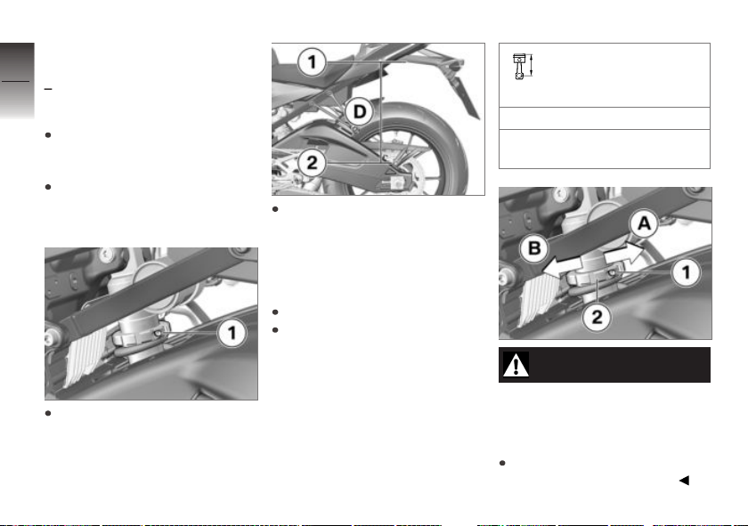
Adjusting spring preload
5
at rear wheel
without Dynamic Damping
70
Control (DDC)
Park motorcycle, ensuring that
support surface is firm and
level.
Make sure there is no load on
the motorcycle, removing any
cargo or luggage.
z
Setting
Loosen screw 1 with tool from
onboard tool kit.
OE
Hold motorcycle in vertical position (not with side stand) and
measure distance D between
lower edge 1 of license-plate
carrier and screw 2 of chain
guard.
Load motorcycle with driver.
With the assistance of a helper,
measure distance D between
points 1 and 2 again and calculate difference (spring deflection) between the measured
values.
Adjustment of spring
preload dependent on
loading
Spring deflection of rear wheel
0.31...0.47 in (8...12 mm) (With
rider 187 lbs (85 kg))
WARNING
Uncoordinated settings of
spring preload and spring
strut damping.
Poorer handling.
Adjust damping characteristic
to changed spring preload.
Page 73
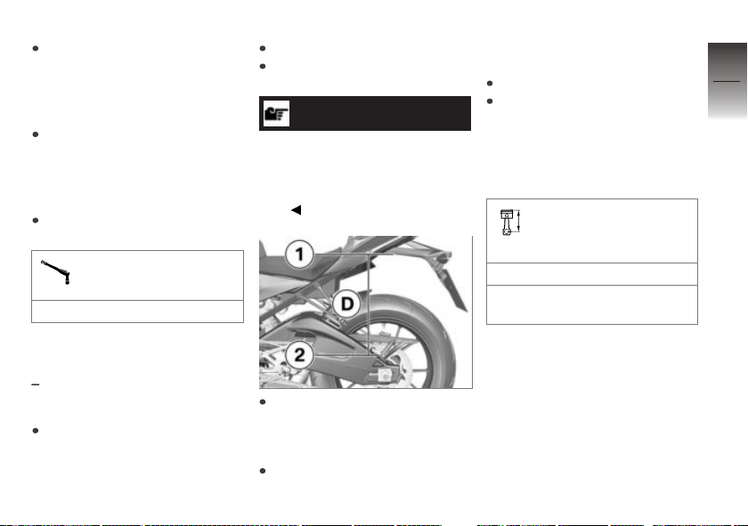
To increase the spring deflection (reduce spring preload),
use the tool from the onboard
tool kit to turn the adjustment
ring 2 in direction B.
To decrease the spring deflection (increase spring preload),
use the tool from the onboard
tool kit to turn the adjustment
ring 2 in direction A.
Tighten screw 1 to specified
torque.
Screw on adjustment
ring
2 lb/ft (3 Nm)
Adjusting spring preload
at rear wheel
with Dynamic Damping Control
OE
(DDC)
Park motorcycle, ensuring that
support surface is firm and
level.
Switch on ignition.
Start engine to avoid discharging battery.
NOTICE
Settings on the DDC system
are only possible with the ignition switched on, as the electric valves are only active in this
case.
Hold motorcycle in vertical position, preferably with the help
of a second person (not the
side stand).
Measure distance D between
lower edge 1 of license-plate
carrier and screw 2 of chain
guard.
Load motorcycle with driver.
With the assistance of a helper,
measure distance D between
points 1 and 2 again and calculate difference (spring deflection) between the measured
values.
Adjustment of spring
preload dependent on
loading
Spring deflection of rear wheel
0.31...0.47 in (8...12 mm) (With
rider 187 lbs (85 kg))
5
71
z
Setting
Page 74
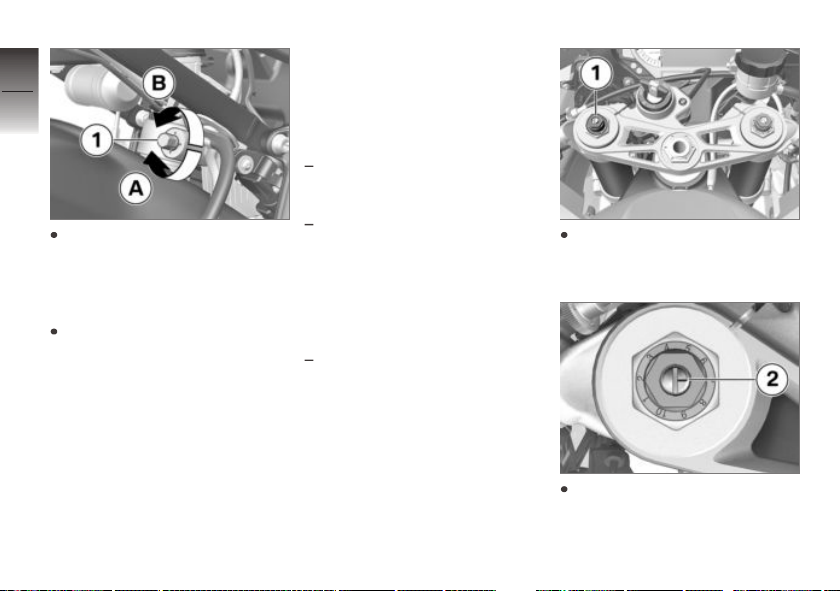
5
72
To decrease the spring deflec-
z
Setting
tion (increase spring preload),
use the tool from the onboard
tool kit to turn the adjustment
ring 1 in direction A.
To increase the spring deflection (reduce spring preload),
use the tool from the onboard
tool kit to turn the adjustment
ring 1 in direction B.
Damping
Setting
Damping must be adjusted to the
road conditions and the spring
preload.
A rough road surface requires
softer damping than a smooth
road surface.
An increase in spring preload
requires firmer damping, a reduction in spring preload requires softer damping.
Adjusting compression
damping on front wheel
without Dynamic Damping
Control (DDC)
OE
Adjust compression damping
with adjusting screw 1 and red
scale on left-hand fork leg.
To increase damping: turn adjusting screw with tool from
onboard tool kit so that mark-
Page 75
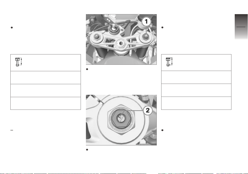
ing 2 points to higher figure on
scale.
To decrease damping: turn
adjusting screw with tool from
onboard tool kit so that marking 2 points to lower figure on
scale.
Compression stage, basic setting, front
Position 2 (comfortable setting
with rider 187 lbs (85 kg))
Position 4 (standard setting
with rider 187 lbs (85 kg))
Position 8 (sport-oriented setting with rider 187 lbs (85 kg))
Adjust rebound-stage damping with adjusting screw 1 and
yellow scale on right-hand fork
leg.
ing 2 points to a higher scale
figure.
To decrease damping: turn
adjusting screw with tool from
onboard tool kit so that marking 2 points to a lower figure
on the scale.
Rebound stage, basic
setting, front
Position 2 (comfortable setting
with rider 187 lbs (85 kg))
Position 4 (standard setting
with rider 187 lbs (85 kg))
Position 7 (sport-oriented setting with rider 187 lbs (85 kg))
5
73
z
Setting
Rebound-stage damping
on front wheel
without Dynamic Damping
Control (DDC)
OE
Factory settings at front
wheel
Use following specification data
to adjust to factory settings.
To increase damping: turn adjusting screw with tool from
onboard tool kit so that mark-
Page 76
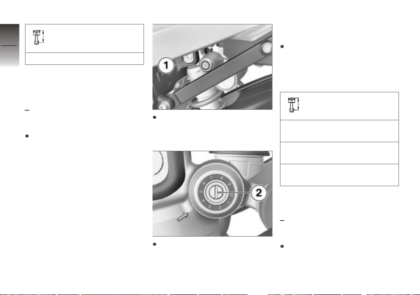
5
74
Factory settings for
jounce/rebound at front
Position 4
Adjusting compression
damping (jounce) at rear
wheel
without Dynamic Damping
Control (DDC)
z
Setting
Park motorcycle, ensuring that
support surface is firm and
level.
OE
Adjust compression damping
with adjusting screw 1 and red
scale.
To increase damping: turn adjusting screw with tool from
onboard tool kit so that mark-
ing 2 points to a higher scale
figure.
To decrease damping: turn
adjusting screw with tool from
onboard tool kit so that marking 2 points to a lower figure
on the scale.
Compression stage, basic setting, rear
Position 2 (comfortable setting
with rider 187 lbs (85 kg))
Position 4 (standard setting
with rider 187 lbs (85 kg))
Position 9 (sport-oriented setting with rider 187 lbs (85 kg))
Adjusting rebound-stage
damping at rear wheel
without Dynamic Damping
Control (DDC)
Park motorcycle, ensuring that
support surface is firm and
level.
OE
Page 77
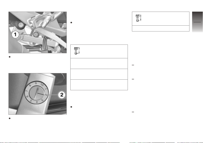
Adjust rebound-stage damping
with adjusting screw 1 and yellow scale.
To increase damping: turn adjusting screw with tool from
onboard tool kit so that mark-
ing 2 points to a higher scale
figure.
To decrease damping: turn
adjusting screw with tool from
onboard tool kit so that marking 2 points to a lower figure
on the scale.
Rebound stage, basic
setting, rear
Position 2 (comfortable setting
with rider 187 lbs (85 kg))
Position 4 (standard setting
with rider 187 lbs (85 kg))
Position 7 (sport-oriented setting with rider 187 lbs (85 kg))
Factory settings at rear
wheel
Use the following specification
data to adjust to factory settings.
Factory settings for
jounce/rebound at rear
Position 4
DDC
Setting
Damping must be adjusted to the
road conditions and the spring
preload.
A rough road surface requires
softer damping than a smooth
road surface.
An increase in spring preload
requires firmer damping, a reduction in spring preload requires softer damping.
Adjusting damping on rear
wheel
with Dynamic Damping Control
OE
(DDC)
5
75
z
Setting
Page 78
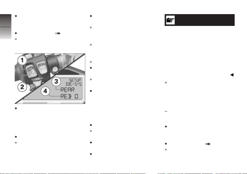
Park motorcycle, ensuring that
support surface is firm and
5
level.
76
Select submenu ( 113).
The SETUP DDC-SYS submenu has been selected.
z
Setting
To adjust the rebound at the
rear wheel, briefly press TRIP 1
or SET 2 repeatedly until in
line 3 REAR and in line 4
REB: (Rebound) is displayed.
Press and hold SET 2.
The value next to REB:
flashes.
Adjust damping as desired with
TRIP 1 and SET 2.
+1 … +7: Damping increase
in a maximum of seven steps
(harder).
-1 … -7: Damping decrease
in a maximum of seven steps
(softer).
0: Factory setting
Press and hold SET 2 until displayed value no longer flashes.
The value for the current riding
mode is saved.
To adjust the rebound at the
rear wheel, briefly press TRIP 1
or SET 2 repeatedly until in
line 3 REAR and in line 4
COM: (Compression) is dis-
played.
Press and hold SET 2.
The value next to COM:
flashes.
Adjust damping as desired with
TRIP 1 and SET 2.
Press and hold SET 2 until displayed value no longer flashes.
NOTICE
Damping is adjusted and saved
separately for all riding modes in
the SETUP DDC-SYS submenu.
Damping is also adjusted and
saved separately for the DDC
modes DDC SPORT, DDC
RACE and DDC SLICK pos-
sible in the USER riding mode.
The value for the current riding
mode is saved.
Adjusting damping on
front wheel
with Dynamic Damping Control
OE
(DDC)
Park motorcycle, ensuring that
support surface is firm and
level.
Select submenu ( 113).
The SETUP DDC-SYS submenu has been selected.
Page 79
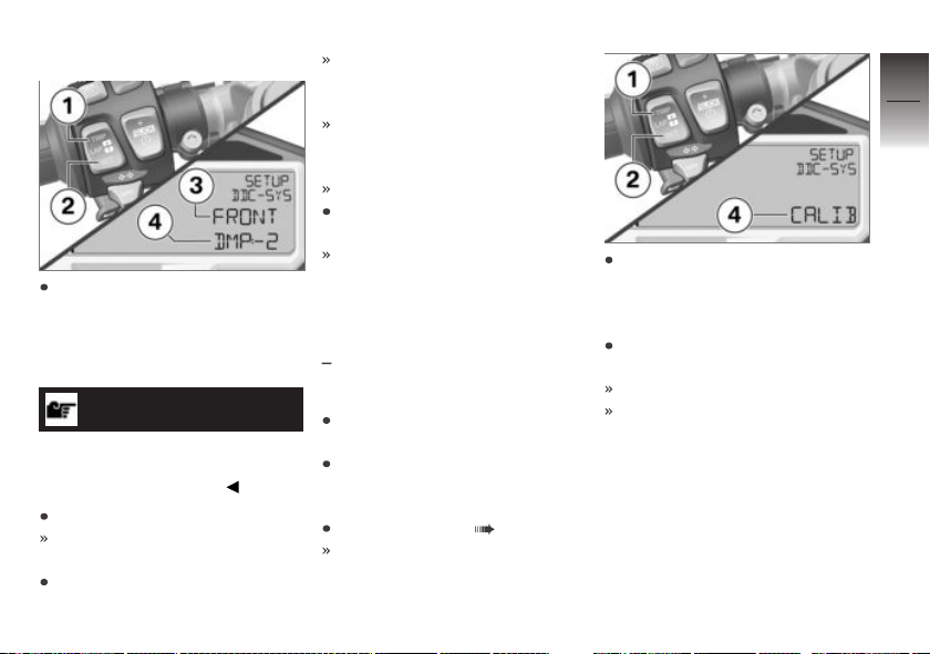
FRONT DMP Adjusting
The adjust damping, briefly
press TRIP 1 or SET 2 repeatedly until in line 3 FRONT is
displayed and in line 4 DMP:
(Damping).
NOTICE
The display differs when a spring
travel sensor for the front forks is
used (racing accessory).
Press and hold SET 2.
The value next to DMP:
flashes.
Adjust damping as desired with
TRIP 1 and SET 2.
+1 … +7: Damping increase
in a maximum of seven steps
(harder).
-1 … -7: Damping decrease
in a maximum of seven steps
(softer).
0: Factory setting
Press and hold SET 2 until displayed value no longer flashes.
The value for the current riding
mode is saved.
Performing zero position
alignment
with Dynamic Damping Control
OE
(DDC)
Place motorcycle on side stand
or a suitable auxiliary stand.
During the alignment, do not sit
on the motorcycle and remove
any cargo or luggage.
Select submenu ( 113).
The SETUP DDC-SYS submenu has been selected.
To set the zero position, briefly
press TRIP 1 or SET 2 repeatedly until CALIB (Calibration)
is displayed in line 4.
Press and hold SET 2 until
CALIB begins to flash.
CALIB flashes.
Zero position is calibrated.
5
77
z
Setting
Page 80
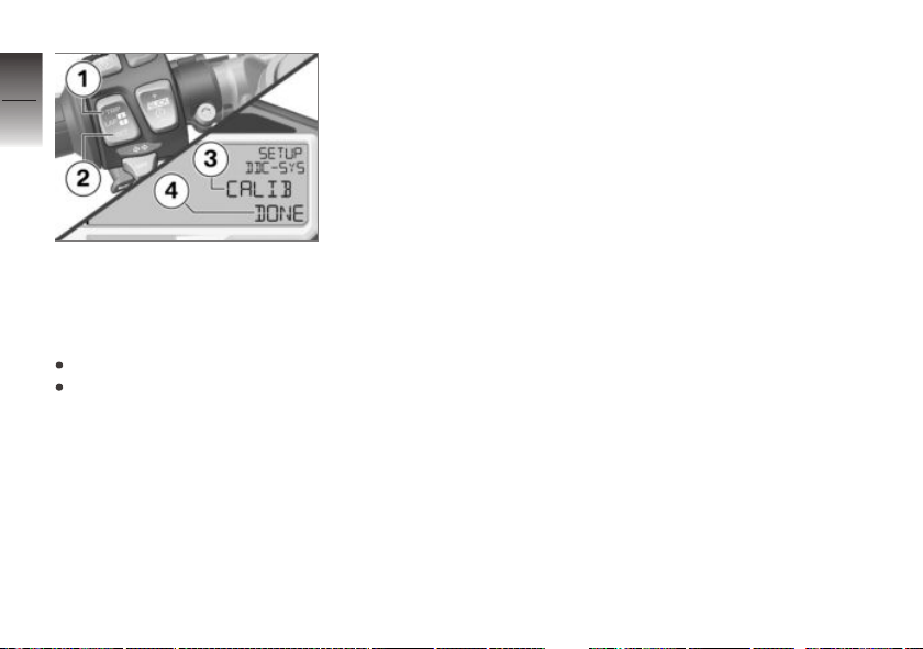
5
78
If the zero position alignment has
z
Setting
been carried out successfully,
CALIB DONE is displayed in
line 3 and 4.
If CALIB FAIL is displayed:
Repeat alignment.
If CALIB DONE is not
displayed after repeated
calibration, please contact a
BMW authorized workshop,
preferably an authorized
BMW Motorrad retailer.
Page 81

Riding
Safety instructions . . . . . . . . . . . . . . . . . . 80
Checklist. . . . . . . . . . . . . . . . . . . . . . . . . . . . 81
Starting . . . . . . . . . . . . . . . . . . . . . . . . . . . . . 82
Breaking in. . . . . . . . . . . . . . . . . . . . . . . . . . 86
Shifting gears . . . . . . . . . . . . . . . . . . . . . . . 87
Brakes . . . . . . . . . . . . . . . . . . . . . . . . . . . . . . 88
Parking your motorcycle . . . . . . . . . . . . 90
Refueling . . . . . . . . . . . . . . . . . . . . . . . . . . . 91
Secure motorcycle for transport . . . . 93
6
79
z
Riding
Page 82
Safety instructions
6
Rider's Equipment
80
Do not ride without the correct
clothing. Always wear:
Helmet
Rider's suit
Gloves
Boots
This applies even to short
z
Riding
journeys, and to every season
of the year. Your authorized
BMW Motorrad retailer will be
happy to advise you and has
the correct clothing for every
purpose.
Loading
WARNING
Reduced riding stability
caused by overloading and
uneven loading
Accident hazard
Do not exceed the gross
weight limit and observe the
loading information.
Adjust spring preload and
damping rate for the current
gross vehicle weight.
Speed
If you ride at high speed, always
bear in mind that various boundary conditions can adversely affect the handling of your motorcycle:
Settings of spring-strut and
shock absorber system
Imbalanced load
Loose clothing
Insufficient tire inflation pressure
Poor tire tread
Etc.
Risk of poisoning
Exhaust fumes contain carbon
monoxide, which is colorless and
odorless but highly toxic.
WARNING
Harmful exhaust gas
Danger of suffocation
Do not inhale exhaust fumes.
Do not run the engine in
closed rooms.
Burn hazard
CAUTION
Intense heating up of engine
and exhaust system while
riding
Burn hazard
After parking the motorcycle,
make sure that no persons
or objects come into contact
with the engine and exhaust
system.
Page 83

Catalytic converter
If misfiring causes unburned fuel
to enter the catalytic converter,
there is a danger of overheating
and damage.
The following must be observed:
Do not run the fuel tank dry.
Do not run the engine with the
spark-plug cap removed.
Stop the engine immediately if
it misfires.
Use unleaded fuel only.
Comply with all specified maintenance intervals.
ATTENTION
Unburned fuel in the catalytic
converter
Damage to catalytic converter
Note the points listed for
protection of the catalytic
converter.
Danger of overheating
ATTENTION
Engine idling for a lengthy
period while at a standstill
Overheating caused by insufficient cooling, in extreme cases
motorcycle fire
Do not allow the engine to idle
unnecessarily.
After starting, ride off
immediately.
Modifications
ATTENTION
Modifications to the motorcycle (e.g. engine control
unit, throttle valves, clutch)
Damage to the affected parts,
failure of safety-relevant functions, expiration of warranty
Do not make any
modifications.
Checklist
Observe checklist
Use the following checklist to
check your motorcycle at regular intervals.
Before every journey:
Check operation of the brake
system.
Check operation of the lighting
and signal system.
Check clutch function ( 165).
Checking tire tread depth
( 168).
Check secure holing of cases
and luggage.
At every third refueling
stop
without Dynamic Damping
Control (DDC)
Adjusting spring preload at rear
wheel ( 70).
OE
6
81
z
Riding
Page 84
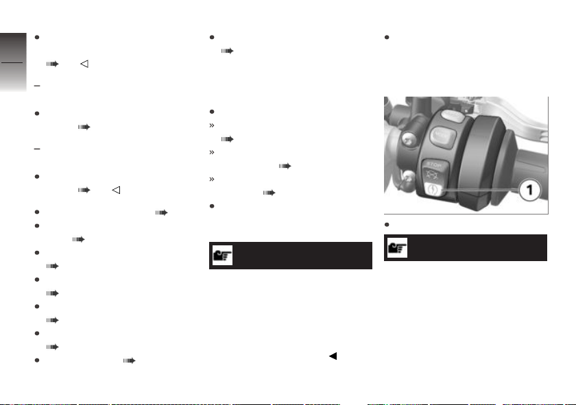
Adjusting compression
damping (jounce) at rear wheel
6
( 74).
82
with Dynamic Damping Control
OE
(DDC)
Adjusting spring preload at rear
wheel ( 71).
with Dynamic Damping Control
OE
(DDC)
z
Riding
Adjusting damping on rear
wheel ( 75).
Check engine oil level ( 159).
Check front brake pad thickness ( 161).
Check rear brake pad thickness
( 162).
Check front brake fluid level
( 163).
Checking rear brake fluid level
( 164).
Checking coolant level
( 166).
Lubricate chain ( 189).
Checking chain tension
( 189).
Starting
Starting engine
Switch on ignition.
Pre-Ride-Check is carried out.
( 83)
ABS self-diagnosis is
performed. ( 84)
ASC self-diagnosis is performed. ( 84)
Engage neutral, or pull back
clutch lever if a gear is engaged.
NOTICE
You cannot start the motorcycle
with the side stand extended and
a gear engaged. The engine will
switch itself off if it is started with
the transmission in neutral and
then a gear is engaged before
retracting the side stand.
For cold starts and at low ambient temperatures: pull lever
to disengage clutch and twist
throttle grip slightly.
Press starter button 1.
NOTICE
The starting attempt is automatically interrupted if battery voltage
is too low. Recharge the battery
before you attempt to start the
engine again, or use jumper cables and a donor battery to start.
Page 85
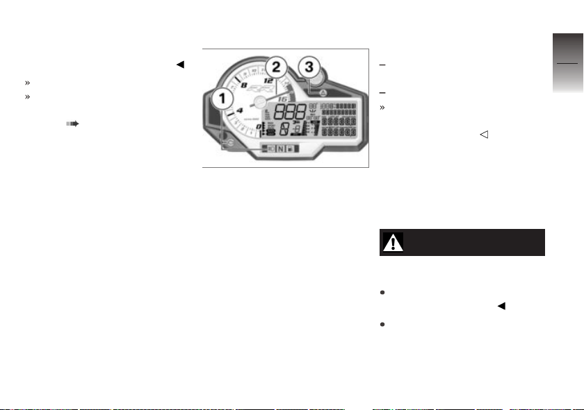
More detailed information can
be found in the "Maintenance"
chapter under "Jump-starting".
Engine starts.
Consult the troubleshooting
chart if the engine refuses to
start. ( 202)
Pre-Ride-Check
After switching off the ignition,
the instrument cluster carries out
a test on the warning lights and
the engine speed display (the
Pre-Ride-Check). Starting the
engine before the test routine is
completed will cancel the remainder of the routine.
Phase 1
The indicator and warning lights
1 light up and the universal warning light 3 lights up in yellow.
The tachometer needle 2 is
run up to the maximum engine
speed.
All segments are shown in the
display.
Phase 2
The universal warning light
changes from yellow to red.
Phase 3
The tachometer needle drops
back to zero.
The indicator and warning lights
go out.
with ABS Pro
or
with ABS Pro
OA
OE
ABS Pro is displayed when
the RAIN SPORT or RACE
riding mode is set.
The display reverts to the standard format. The odometer is
displayed.
Should one of the warning lights
fail to appear:
WARNING
Defective warning lights
Lack of display of malfunctions
Check the display of all indicator and warning lights.
Have the malfunction corrected
as soon as possible at an
authorized service facility,
preferably an authorized
BMW Motorrad Retailer.
6
83
z
Riding
Page 86
ABS self-diagnosis
6
The readiness for operation of
the BMW Motorrad Race ABS
84
is checked by the self-diagnosis.
The self-diagnosis routine runs
automatically when you switch on
the ignition. To check the wheel
speed sensors, the motorcycle
must be driven a few yards.
Phase 1
z
Riding
Check on system components
monitored by diagnostic system while motorcycle is parked.
ABS indicator light flashes.
Phase 2
Check wheel sensors while
starting off.
ABS indicator light flashes.
ABS self-diagnosis
completed
The ABS indicator and warning
light goes out.
If an ABS error is displayed after
the ABS self-diagnosis is completed:
It remains possible to continue
riding. It must be noted that
the ABS and integral function
is not available at all or is restricted.
Have the malfunction corrected
as soon as possible at an
authorized service facility,
preferably an authorized
BMW Motorrad retailer.
ASC self-diagnosis
The self-diagnosis routine
is determining whether
BMW Motorrad ASC is ready for
operation. The self-diagnosis
routine runs automatically when
you switch on the ignition.
Phase 1
Check on system components
monitored by diagnostic system while motorcycle is parked.
ASC indicator and warning
light flashes slowly.
Phase 2
Checking the diagnosable system components while driving.
In order that the ASC self-diagnosis can be completed, the
motorcycle must be traveling
at a speed of at least 3 mph
(5 km/h).
ASC indicator and warning
light flashes slowly.
ASC self-diagnosis
completed
The ASC symbol is no longer
displayed.
Page 87
If an ASC error is displayed after
the ASC self-diagnosis is completed:
It remains possible to continue
riding. It must be noted that
the ASC function is not available.
Have the malfunction corrected
as soon as possible at an
authorized service facility,
preferably an authorized
BMW Motorrad Retailer.
DTC self-diagnosis
with Dynamic Traction Control
OE
(DTC)
The self-diagnosis routine
is determining whether
BMW Motorrad DTC is ready for
operation. The self-diagnosis
routine runs automatically when
you switch on the ignition.
Phase 1
Check on system components
monitored by diagnostic system while motorcycle is parked.
DTC indicator light flashes
slowly.
Phase 2
Checks diagnosis-capable system components when motorcycle starts to move.
DTC indicator light flashes
slowly.
DTC self-diagnosis
completed
The DTC symbol is no longer
displayed.
Check the display of all indicator and warning lights.
DTC self-diagnosis not
completed
The DTC function is not available, as the self-diagnosis
function has not been completed. (To check wheel sensors, motorcycle must reach
a minimum speed with engine running: min 3 mph (min
5 km/h))
If a DTC error is indicated after
the DTC self-diagnosis is completed:
It remains possible to continue riding. It must be noted
that the availability of the DTC
function is restricted or it is not
available at all.
Have the malfunction corrected
as soon as possible at an
authorized service facility,
preferably an authorized
BMW Motorrad Retailer.
6
85
z
Riding
Page 88
Breaking in
6
Engine
86
In the period preceding the
initial inspection attempt to
change rpm and engine load as
frequently as possible, avoiding
extended periods at constant
rpm.
Choose curvy, slightly hilly sections of road if possible.
z
Riding
Observe the engine run-in
speeds.
Engine run-in speed
<7000 min-1(Odometer reading 0...186 miles (0...300 km))
<9000 min-1(Odometer
reading 186...621 miles
(300...1000 km))
no full throttle (Odometer
reading 0...621 miles
(0...1000 km))
Observe mileage, after which
the running-in check should be
performed.
NOTICE
The speed is limited by the
engine management system up
to the running-in check. This
speed monitoring function is
switched off during the runningin check by your authorized
BMW Motorrad retailer.
Mileage until running-in
check
311...746 miles
(500...1200 km)
Speed monitoring
function until running-in
check
max 9000 min
-1
Brake pads
New brake pads must be run in
before they achieve their optimum friction force. This initial
reduction in braking efficiency
can be compensated for by exerting greater pressure on the
brake levers.
WARNING
New brake pads
Extension of the braking distance,
accident hazard
Brake early.
Tires
New tires have a smooth surface. This must be roughened by
riding in a restrained manner at
various lean angles until the tires
are run in. This running in procedure is essential if the tires are to
achieve maximum grip.
Page 89
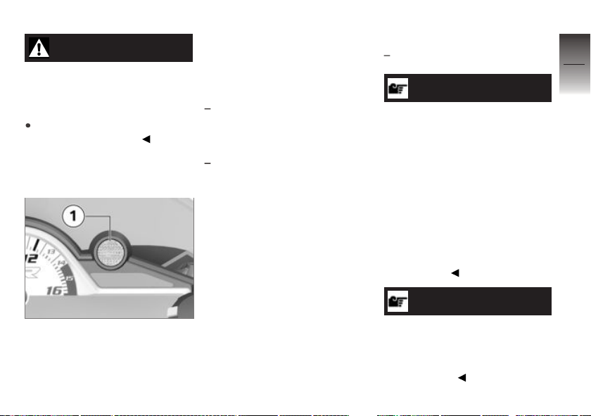
WARNING
Loss of adhesion of new tires
on wet roads and at extreme
angles
Accident hazard
Always think well ahead and
avoid extreme angles.
Shifting gears
Shiftpoint light
The shiftpoint light 1 indicates
two engine speed thresholds to
the driver:
Shifting speed
During driving the shiftpoint light
indicates the speed at which the
rider should shift into the nexthighest gear.
Shiftpoint light flashes at the
preset frequency: engine
speed will soon reach upshift
rpm
Shiftpoint light goes out: shifting speed reached
The engine rpm limits and the
upshift light's display characteristics can both be adjusted in the
SETUP menu.
Speed limit
If the shiftpoint light flashes or
lights up during operation while
SPEED ! simultaneously ap-
pears in the display this means
that the preset speed has been
exceeded.
Pro shift assistant
with Pro shift assistant
NOTICE
The Pro gearshift assistant
provides help with upward and
downward gear shifts without the
clutch or the accelerator having
to be operated. This is not an
automatic transmission. The rider
is an essential part of the system
and makes the decision as to
when to change gear.
More detailed information on Pro
Gear-shift Assistance can be
found in the section "Technology in detail".
NOTICE
When changing gear using the
Pro Gear-shift Assistance function, the cruise-control system
is automatically deactivated for
safety reasons.
OE
6
87
z
Riding
Page 90
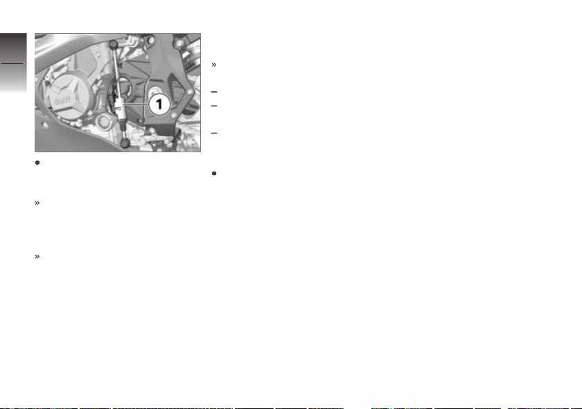
6
88
The gears are shifted into as
z
Riding
usual with foot force on the
shift lever.
The sensor 1 on the gear-shift
rod detects the intention to
change gear and initiates gearshift assistance.
When driving at constant
speed in low gears at high
revs, changing gear without
using the clutch can result in
major load change reactions.
BMW Motorrad recommends
only changing gear using the
clutch in such situations. The
shifting assistant should not
be used in the area of the revlimiter.
No shifting support is provided
in the following situations:
With the clutch operated.
If the gear lever is not in the
zero position
When upshifting with the throttle closed (overrun mode) or
when decelerating
To be able to make another
gear shift using gear-shift assistance, the gear lever must
be fully released after the first
gear change.
Brakes
How do you achieve
the shortest stopping
distances?
The dynamic load distribution between the front and rear wheel
changes during braking. The
heavier you brake, the greater
the weight transfer to the front
wheel. Increases in the load on
an individual wheel are accompanied by a rise in the effective
braking force that the wheel can
provide.
To achieve the shortest possible braking distance, the front
brake must be applied quickly
and with progressively greater
levels of force. This procedure
provides ideal exploitation of the
extra weight transfer to the front
wheel. The clutch should also be
disengaged at the same time.
Locking up of the front wheel
is prevented by BMW Motorrad
Race ABS.
With the frequently instructed
"forced braking," in which the
brake pressure is generated as
quickly as possible and with great
force, dynamic load distribution lags behind the progressive increases in deceleration
rate and the braking force cannot
be completely transferred to the
Page 91
road surface. Due to the missing wheel load, the ABS must
already prevent a tendency of the
front wheel to lock up with minimal braking action. This results
in a reduced braking action.
Descending mountain
passes
WARNING
Braking only with the rearwheel brake when descending mountain passes
Reduced of braking action, destruction of the brakes caused by
overheating
Use both front and rear brakes,
and make use of the engine's
braking effect as well.
Wet, soiled brakes
Moisture and dirt on the brake
rotors and the brake pads result
in a decrease in the braking action.
Delayed or poorer braking action
must be expected in the following situations:
When driving in the rain and
through puddles.
After washing the vehicle.
When driving on roads spread
with salt.
After working on the brakes
due to oil or grease residues.
When driving on soiled roads
or offroad.
WARNING
Poorer braking action due to
moisture and dirt
Accident hazard
Brake until brakes are dry or
clean; clean if necessary.
Brake early until the full braking
action is available again.
ABS Pro
with ABS Pro
or
with ABS Pro
Physical riding limits
WARNING
Braking in curves
Danger of falling despite ABS Pro
The rider is always responsible for adapting his/her driving
style.
Do not reduce the system's extra safety margin with careless
riding or unnecessary risks.
Availability of ABS Pro
ABS Pro is available in the
RAIN, SPORT and RACE riding modes.
OA
OE
6
89
z
Riding
Page 92
The SLICK and USER riding
modes are not supported by
6
the ABS Pro function.
90
Falling cannot be excluded
Although ABS Pro represents
valuable support and an enormous safety advantage for the
rider when braking in the inclined
position, it by no means rede-
z
Riding
fines the physical riding limits. It
is still possible to exceed those
limits through misjudgments or
riding errors. In extreme cases
this my result in a fall.
ABS Pro was not developed
for the racetrack
ABS Pro was not developed for
the racetrack to increase the individual braking performance in the
inclined position.
On the contrary, ABS Pro helps
make riding your motorcycle on
public roads even safer. When
braking due to unexpected haz-
ards in curves, locking-up and
slipping of the wheels is prevented within the scope of the
physical riding limits.
On the racetrack
The first few times riding on the
racetrack are considerably safer
for less experienced riders with
ABS Pro in the RAIN, SPORT
and RACE riding modes.
NOTICE
ABS Pro was not developed to
increase the individual braking
performance in the inclined position in the limit range.
Use on public roads
ABS Pro was purposely designed
for use on public roads.
Parking your motorcycle
Side stand
Switch off engine.
On a grade, the motorcycle
should always face uphill; select 1st gear.
ATTENTION
Poor ground conditions in
area of stand
Component damage cause by
tipping over
Always check that the ground
under the stand is level and
firm.
Fold out side stand and park
motorcycle.
ATTENTION
Loading of the side stand
with additional weight
Component damage cause by
tipping over
Page 93
Do not sit on the motorcycle
when it is parked on the side
stands.
If the slope of the road permits,
turn the handlebars to the left.
Refueling
Fuel specifications
Requirement
For optimal fuel economy, the
gasoline should be sulfur-free or
very low in sulfur content.
ATTENTION
Refueling with leaded fuel
Damage to catalytic converter
Do not refuel with leaded gasoline or gasoline with metallic
additives, e.g. manganese or
iron.
ATTENTION
Use of Ethanol E85 as fuel
Damage to the engine and fuel
supply
Do not refuel with E85, i.e. fuel
with an ethanol content of 85
%, or with Flex Fuel.
Fuels with a maximum ethanol
content of 10 %, i.e. E10, may
be used for refueling.
Recommended fuel quality
Premium grade unleaded fuel
(max. 10 % ethanol, E10)
91 AKI (98 ROZ/RON)
91 AKI
Alternative fuel quality
Super unleaded (minor restrictions with regard to power and
fuel consumption) (max. 10 %
ethanol, E10)
89 AKI (95 ROZ/RON)
89 AKI
Refueling
WARNING
Fuel is highly flammable
Fire and explosion hazard
Do not smoke. Never bring
a naked flame near the fuel
tank.
WARNING
Escaping of fuel due to expansion under exposure to
heat with overfilled fuel tank
Accident hazard
Do not overfill the fuel tank.
ATTENTION
Contact of fuel and plastic
surfaces
Damage to surfaces (become
unattractive or cloudy)
Immediately clean plastic surfaces after contact with fuel.
6
91
z
Riding
Page 94
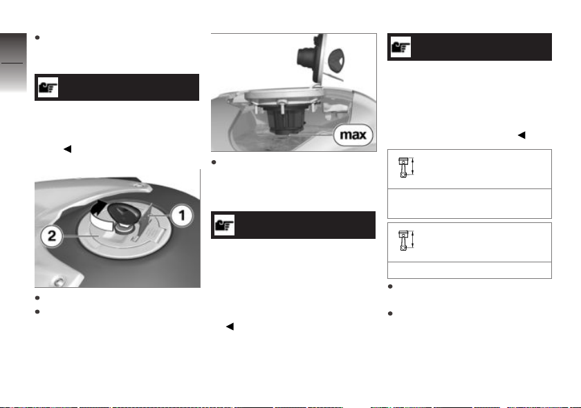
Make sure ground is level and
firm and place motorcycle on
6
side stand.
92
NOTICE
The available fuel tank volume
can only be optimally used with
the vehicle standing on the side
stand.
z
Riding
Open protective cover 1.
Unlock fuel-tank cap 2 with ignition key by turning clockwise,
then swivel it up.
Refuel with a fuel meeting the
specifications above, continuing until fuel is no higher than
lower edge of filler neck.
NOTICE
When refueling after running on
fuel reserve, the resulting total
fuel quantity must be greater
than the fuel reserve, so that the
new filling level is detected and
the fuel warning light is switched
off.
NOTICE
The "usable fuel quantity" specified in the technical data is the
fuel quantity, which can be refueled if the fuel tank was completely emptied, i.e., if the engine
dies off due to lack of fuel.
Usable fuel quantity
Approx. 4.6 gal (Approx.
17.5 l)
Fuel reserve
Approx. 1.1 gal (Approx. 4 l)
Press fuel tank cap down firmly
to close.
Remove ignition key and close
protective cover.
Page 95
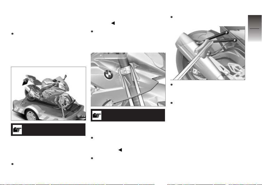
Secure motorcycle for transport
Protect all component surfaces
against which straps are routed
against scratching. For example, use adhesive tape or soft
cloths.
ATTENTION
Motorcycle tips to the side
when raising
Component damage cause by
tipping over
Secure the motorcycle against
tipping to the side, preferably
with the assistance of a second
person.
Push motorcycle onto transport
surface, and do not place on
side stand.
ATTENTION
Pinching of components
Component damage
Do not pinch components,
e.g. brake lines or wiring
harnesses.
Lay straps at front over lower
fork bridge on both sides.
Tension straps downward.
Fasten rear straps on both
sides to the passenger footpegs and then tighten them.
Tension all straps evenly; the
motorcycle should be pulled
down against its springs with
the suspension compressed as
much as possible.
6
93
z
Riding
Page 96

6
94
z
Riding
Page 97

On the racetrack
Display for racing mode. . . . . . . . . . . . . 96
LAPTIMER . . . . . . . . . . . . . . . . . . . . . . . . . 98
RACE INFO. . . . . . . . . . . . . . . . . . . . . . . . 103
SETUP MENU . . . . . . . . . . . . . . . . . . . . . 111
SETUP DDC-SYS . . . . . . . . . . . . . . . . . 117
SETUP EQUIPMENT . . . . . . . . . . . . . . 118
SETUP RACETRACK . . . . . . . . . . . . . 120
SETUP USER-MODE . . . . . . . . . . . . . 125
DTC . . . . . . . . . . . . . . . . . . . . . . . . . . . . . . . 127
Start of race . . . . . . . . . . . . . . . . . . . . . . . 128
Speed limiter for pit lane . . . . . . . . . . . 130
Mirror removal and installation . . . . . 131
Removing and installing license-
plate carrier . . . . . . . . . . . . . . . . . . . . . . . . 132
Removing and installing front turn
indicator . . . . . . . . . . . . . . . . . . . . . . . . . . . 134
Shift pattern reversal . . . . . . . . . . . . . . . 136
Connector for optional acces-
sories . . . . . . . . . . . . . . . . . . . . . . . . . . . . . . 138
7
95
z
On the racetrack
Page 98
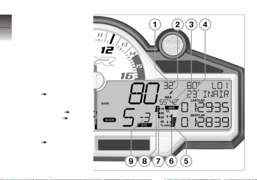
Display for racing mode
7
Multifunction display
96
1 Current angle of inclination
during cornering
2 Direction for angle of incli-
nation
\ = left
| = vertical
/ = right
3 Maximum angle of inclina-
tion for left and right
Factory setting for BANK
DISP ( 119)
4 ABS control intervention
z
On the racetrack
during braking
Deactivate ABS ( 50).
Activating ABS ( 51).
5 Current deceleration during
braking
Factory setting for BRAKE
DISP ( 120)
6 Maximum deceleration
7 Maximum DTC torque re-
duction
Page 99

8 DTC torque reduction
Factory setting for DTC
DISP ( 119)
9 DTC setting
with Dynamic Traction
Control (DTC)
Adapt DTC ( 127).
OE
7
97
z
On the racetrack
Page 100
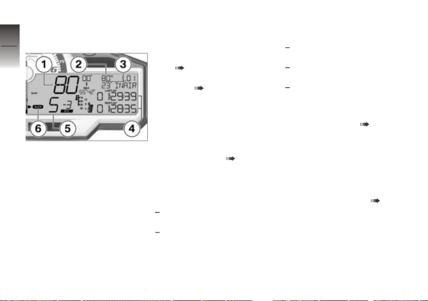
LAPTIMER
7
Multifunction display
98
1 Speed
2 Coolant temperature
3 Intake air temperature
z
On the racetrack
4 LAP TIMER
The display in these lines
can be switched over.
Individualize LAPTIMER
( 100).
LAPTIMER display structure ( 121)
In illustration:
RUN: Running time of the
current lap.
BESTLAP: Fastest of the
currently saved laps.
5 Gear indicator
6 Riding mode ( 53)
Marking displayed value
The following times can be
shown in the third line:
The time of the previous lap is
marked with "LASTLAP".
The running time of the current
lap.
The following times can be
shown in the fourth line:
The fastest of the stored laps,
marked with "BESTLAP".
The all-time best lap time,
without a marking.
The running time of the current
lap.
The possible combinations are
described on Page ( 121).
The stopped time of the preceding lap is shown briefly at the
start of each new lap before the
display switches over to the running time of the current lap. The
duration of this delay can be set
as described on Page ( 123).
 Loading...