

Page 1
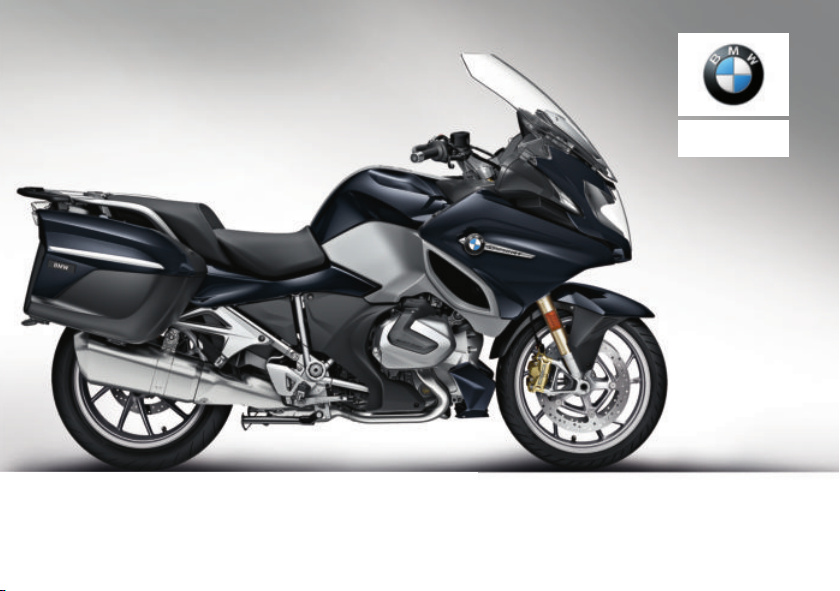
Rider's manual
R 1250 RT
BMW Motorrad
Page 2

Vehicle data/dealership details
Vehicle data
Model
Vehicle Identification Number
Colour code
Date of first registration
Registration number
Dealership details
Person to contact in Service department
Ms/Mr
Phone number
Dealership address/phone number (company stamp)
Page 3

Welcome to BMW
We congratulate you on
your choice of a vehicle from
BMW Motorrad and welcome
you to the community of BMW
riders. Familiarise yourself with
your new vehicle so that you can
ride it safely and confidently in all
traffic situations.
About this Rider's Manual
Please read this Rider's Manual
carefully before starting to use
your new BMW. It contains important information on how to
operate the controls and how to
make the best possible use of all
your BMW's technical features.
In addition, it contains information on maintenance and care to
help you maintain your vehicle's
reliability and safety, as well as its
value.
This record of the maintenance
work you have had performed on
your vehicle is a precondition for
generous treatment of goodwill
claims.
If the time comes to sell your
BMW, please remember to hand
over this Rider's Manual to the
new owner. It is an important
part of the vehicle.
Suggestions and criticism
If you have questions concerning your vehicle, your authorised
BMW Motorrad dealer will gladly
provide advice and assistance.
We hope you will enjoy riding
your BMW and that all your journeys will be pleasant and safe
BMW Motorrad.
01 40 9 446 691
*01409446691*
Page 4

Table of Contents
1 General instructions ... . 5
Overview . . . . . . . . . . . . . . . . . . . . . 6
Abbreviations and
symbols . . . . . . . . . . . . . . . . . . . . . . 6
Equipment . . . . . . . . . . . . . . . . . . . 7
Technical data . . . . . . . . . . . . . . . 7
Currentness . . . . . . . . . . . . . . . . . . 8
Additional sources of informa-
tion . . . . . . . . . . . . . . . . . . . . . . . . . . . 8
Certificates and operating li-
cences . . . . . . . . . . . . . . . . . . . . . . . 8
Data memory. . . . . . . . . . . . . . . . . 8
Intelligent emergency call
system . . . . . . . . . . . . . . . . . . . . . . 12
2 General views . .. .. .. .. .. 17
General view, left side . . . . . . . 19
General view, right side . . . . . 21
Underneath the seat . . . . . . . . 22
Multifunction switch, left . . . . 23
Multifunction switch,
right . . . . . . . . . . . . . . . . . . . . . . . . . 25
Multifunction switch,
right . . . . . . . . . . . . . . . . . . . . . . . . . 26
Instrument panel . . . . . . . . . . . . 27
3 Status indicators ... .. .. 29
Indicator and warning
lights . . . . . . . . . . . . . . . . . . . . . . . . 30
Meaning of symbols . . . . . . . . . 31
Multifunction display . . . . . . . . 33
Warnings . . . . . . . . . . . . . . . . . . . . 34
Range . . . . . . . . . . . . . . . . . . . . . . . 53
Electronic oil-level check . . . . 53
Ambient temperature.. . . . . . . 54
Tyre pressures . . . . . . . . . . . . . . 54
4 Operation ... . .. .. .. .. .. .. 57
Ignition switch/steering
lock . . . . . . . . . . . . . . . . . . . . . . . . . 58
Ignition with Key-
less Ride . . . . . . . . . . . . . . . . . . . . 60
Emergency off switch (kill
switch) . . . . . . . . . . . . . . . . . . . . . . 66
Intelligent emergency
call . . . . . . . . . . . . . . . . . . . . . . . . . . 66
Lights . . . . . . . . . . . . . . . . . . . . . . . 69
Day run lights . . . . . . . . . . . . . . . 70
Hazard warning lights sys-
tem . . . . . . . . . . . . . . . . . . . . . . . . . 72
Turn indicators . . . . . . . . . . . . . . 72
Multifunction display . . . . . . . . 73
On-board computer . . . . . . . . . 77
Trip recorder . . . . . . . . . . . . . . . . 79
Automatic Stability Control
(ASC) . . . . . . . . . . . . . . . . . . . . . . . 79
Dynamic Traction Control
(DTC) . . . . . . . . . . . . . . . . . . . . . . . 80
Electronic Suspension Ad-
justment (DESA) . . . . . . . . . . . 81
Riding mode . . . . . . . . . . . . . . . . 82
Cruise-control system . . . . . . . 83
Hill Start Control . . . . . . . . . . . . 85
Anti-theft alarm (DWA) . . . . . . 88
Heating. . . . . . . . . . . . . . . . . . . . . . 91
Front seat . . . . . . . . . . . . . . . . . . . 94
Rear seat . . . . . . . . . . . . . . . . . . . . 95
Stowage compartment . . . . . . 97
Central locking system . . . . . . 98
Page 5

5 Adjustment .. .. .. .. . .. . 103
Mirrors . . . . . . . . . . . . . . . . . . . . 104
Headlight . . . . . . . . . . . . . . . . . . 104
Windscreen . . . . . . . . . . . . . . . 104
Instrument panel . . . . . . . . . . 105
Clutch . . . . . . . . . . . . . . . . . . . . . 106
Gearshift lever . . . . . . . . . . . . . 107
Brakes . . . . . . . . . . . . . . . . . . . . 108
Spring preload . . . . . . . . . . . . 109
Damping . . . . . . . . . . . . . . . . . . 111
6 Riding .. .. .. .. .. . .. .. .. . 113
Safety instructions .. . . . . . . 114
Comply with checklist . . . . . 116
Always before riding off . . . 116
Every 3rd refuelling
stop . . . . . . . . . . . . . . . . . . . . . . . 116
Starting. . . . . . . . . . . . . . . . . . . . 117
Running in . . . . . . . . . . . . . . . . 120
Shifting gear . . . . . . . . . . . . . . 121
Brakes . . . . . . . . . . . . . . . . . . . . 122
Parking your motor-
cycle . . . . . . . . . . . . . . . . . . . . . . 124
Refuelling . . . . . . . . . . . . . . . . . 125
Securing motorcycle for
transportation . . . . . . . . . . . . . 129
7 Engineering
details . .. .. .. .. . .. .. .. . 131
General instructions . . . . . . . 132
Antilock Brake System
(ABS). . . . . . . . . . . . . . . . . . . . . . 132
Traction control (ASC/
DTC) . . . . . . . . . . . . . . . . . . . . . . 135
Electronic Suspension Ad-
justment (DESA) . . . . . . . . . 137
Riding mode . . . . . . . . . . . . . . 137
Dynamic Brake Control . . . . 139
Tyre pressure control
(RDC) . . . . . . . . . . . . . . . . . . . . . 140
Shift assistant . . . . . . . . . . . . . 141
Hill Start Control . . . . . . . . . . 143
ShiftCam . . . . . . . . . . . . . . . . . . 144
8 Maintenance . . . .. .. .. . 145
General instructions . . . . . . . 146
Standard toolkit . . . . . . . . . . . 146
Service toolkit . . . . . . . . . . . . . 146
Front-wheel stand . . . . . . . . . 147
Engine oil . . . . . . . . . . . . . . . . . 148
Brake system . . . . . . . . . . . . . 149
Clutch . . . . . . . . . . . . . . . . . . . . . 154
Coolant. . . . . . . . . . . . . . . . . . . . 154
Tyres . . . . . . . . . . . . . . . . . . . . . . 156
Rims and tyres . . . . . . . . . . . . 156
Wheels . . . . . . . . . . . . . . . . . . . . 157
Silencer . . . . . . . . . . . . . . . . . . . 164
Lighting . . . . . . . . . . . . . . . . . . . 165
Jump-starting . . . . . . . . . . . . . 170
Battery . . . . . . . . . . . . . . . . . . . . 171
Fuses . . . . . . . . . . . . . . . . . . . . . 175
Diagnostic connector . . . . . . 176
9 Accessories . .. .. .. . .. . 179
General instructions . . . . . . . 180
Power sockets . . . . . . . . . . . . 180
Cases . . . . . . . . . . . . . . . . . . . . . 181
Topcase. . . . . . . . . . . . . . . . . . . 183
Navigation system . . . . . . . . . 186
10 Care . . .. .. .. .. .. .. .. . . 191
Care products . . . . . . . . . . . . . 192
Washing the vehicle . . . . . . . 192
Cleaning easily damaged
components . . . . . . . . . . . . . . . 193
Care of paintwork . . . . . . . . . 194
Vehicle preservation . . . . . . . 194
Laying up the motor-
cycle . . . . . . . . . . . . . . . . . . . . . . 194
Page 6

Restoring motorcycle to
use . . . . . . . . . . . . . . . . . . . . . . . . 195
11 Technical data . . .. .. 197
Troubleshooting chart . . . . . 198
Screw connections . . . . . . . . 199
Fuel . . . . . . . . . . . . . . . . . . . . . . . 201
Engine oil . . . . . . . . . . . . . . . . . 202
Engine . . . . . . . . . . . . . . . . . . . . 202
Clutch . . . . . . . . . . . . . . . . . . . . . 203
Transmission . . . . . . . . . . . . . . 204
Rear-wheel drive . . . . . . . . . . 205
Frame . . . . . . . . . . . . . . . . . . . . . 205
Chassis and
suspension . . . . . . . . . . . . . . . . 206
Brakes . . . . . . . . . . . . . . . . . . . . 207
Wheels and tyres . . . . . . . . . . 208
Electrical system . . . . . . . . . . 209
Anti-theft alarm. . . . . . . . . . . . 210
Dimensions .. . . . . . . . . . . . . . 211
Weights . . . . . . . . . . . . . . . . . . . 212
Riding specifications . . . . . . 212
12 Service . . .. .. .. .. . .. .. 213
BMW Motorrad Service . . . 214
BMW Motorrad Service
history . . . . . . . . . . . . . . . . . . . . . 214
BMW Motorrad Mobility
services . . . . . . . . . . . . . . . . . . . 215
Maintenance work . . . . . . . . . 215
BMW Service . . . . . . . . . . . . . 215
Maintenance schedule . . . . 219
Maintenance confirma-
tions. . . . . . . . . . . . . . . . . . . . . . . 220
Service confirmations . . . . . 234
13 Appendix . .. .. .. .. .. .. 237
Certificate for electronic
immobiliser . . . . . . . . . . . . . . . . 238
Certificate for remote
key . . . . . . . . . . . . . . . . . . . . . . . . 240
Certificate for Key-
less Ride . . . . . . . . . . . . . . . . . . 244
Certificate for tyre pressure
control (RDC) . . . . . . . . . . . . . 246
14 Index . .. .. .. .. .. .. .. .. 247
Page 7

General instructions
Overview . . . . . . . . . . . . . . . . . . . . . . . . . . . . 6
Abbreviations and symbols . . . . . . . . . . 6
Equipment . . . . . . . . . . . . . . . . . . . . . . . . . . . 7
Technical data . . . . . . . . . . . . . . . . . . . . . . . 7
Currentness . . . . . . . . . . . . . . . . . . . . . . . . . 8
Additional sources of information . . . . 8
Certificates and operating
licences . . . . . . . . . . . . . . . . . . . . . . . . . . . . . . 8
Data memory . . . . . . . . . . . . . . . . . . . . . . . . 8
Intelligent emergency call
system . . . . . . . . . . . . . . . . . . . . . . . . . . . . . . 12
1
5
z
General instructions
Page 8
Overview
1
An important aspect of this
Rider's Manual is that it can
6
be used for quick and easy
reference. Consulting the
extensive index at the end of this
Rider's Manual is the fastest way
to find information on a particular
topic or item. To first read an
overview of your motorcycle,
please go to Chapter 2. All
maintenance and repair work on
the motorcycle is documented
in Chapter 12. This record of
the maintenance work you have
had performed on your vehicle
is a precondition for generous
z
General instructions
treatment of goodwill claims.
When the time comes to sell
your BMW, please remember
to hand over this Rider's Manual;
it is an important part of the motorcycle.
Abbreviations and symbols
CAUTION Low-risk hazard.
Non-avoidance can lead to
slight or moderate injury.
WARNING Medium-risk
hazard. Non-avoidance can
lead to fatal or severe injury.
DANGER High-risk hazard. Non-avoidance leads
to fatal or severe injury.
ATTENTION Special
notes and precautionary
measures. Non-compliance can
lead to damage to the vehicle or
accessory and, consequently, to
voiding of the warranty.
NOTICE Specific instruc-
tions on how to operate,
control, adjust or look after items
of equipment on the vehicle.
Indicates the end of an
item of information.
Instruction.
Result of an activity.
Reference to a page with
more detailed information.
Indicates the end of a
passage relating to specific accessories or items
of equipment.
Tightening torque.
Technical data.
OE Optional extras.
The vehicles are assembled complete with
all the BMW Motorrad
optional extras originally
ordered.
Page 9

OA Optional accessories.
You can obtain
BMW Motorrad
optional accessories
through your authorised
BMW Motorrad dealer;
optional accessories
have to be retrofitted to
the vehicle.
Electronic immobiliser.
EWS
DWA
Anti-theft alarm (Diebstahlwarnanlage).
Anti-lock brake system.
ABS
ASC Automatic Stability Con-
trol.
D-
Electronic chassis and
ESA
suspension adjustment.
DTC Dynamic Traction Con-
trol (optional extra only
in combination with Pro
riding modes).
Tyre pressure monitor-
RDC
ing.
Equipment
When purchasing your BMW motorcycle, you chose a model with
individual equipment. This rider's
manual describes optional equipment (OE) and selected optional
accessories (OA) provided by
BMW. Please make allowance
for the fact that some equipment specifications may be described that you have not selected. Equally, country-specific deviations to the motorcycle shown
are also possible.
If your motorcycle has equipment
that is not described, you will find
the relevant description in a separate manual.
Technical data
All dimensions, weights and
power outputs in the rider's
manual refer to the German
standard DIN (Deutsches Institut
für Normung e. V.) and comply
with its specified tolerances.
Technical data and specifications
in this rider's manual serve as
reference points. The vehiclespecific data may deviate from
these, for example as a result of
selected optional equipment,
the national-market version or
country-specific measuring
procedures. Detailed values
can be taken from the vehicle
registration documents and
signs on the vehicle, or can be
obtained from your authorised
BMW Motorrad Retailer or
another qualified service partner
or specialist workshop. The
specifications in the vehicle
documents always have priority
1
7
z
General instructions
Page 10

over the information provided in
this rider's manual.
1
8
Currentness
The high safety and quality level
of BMW motorcycles is ensured
by constant further development
in the areas of design, equipment
and accessories. This may result in deviations between these
operating instructions and your
motorcycle. Also, mistakes cannot be completely excluded by
BMW Motorrad. Please therefore
understand that we do not accept any liability for claims arising
from incorrect information, draw-
z
General instructions
ings and descriptions.
Additional sources of information
BMW Motorrad Retailer
Your BMW Motorrad Retailer will
be happy to answer any questions you may have.
Internet
The rider's manual for your
vehicle, operating and installation
instructions for any accessories
and general information on
BMW Motorrad, for example
relating to technology, are
available at www.bmw-
motorrad.com/service.
Certificates and operating licences
The certificates for the vehicle
and the official operating licences
for any accessories are available
at www.bmw-motorrad.com/
certification.
Data memory
General
Control units are installed in the
vehicle. Control units process
data that they receive, for example, from vehicle sensors, or
that they generate themselves or
exchange between each other.
Some control units are required
for the vehicle to function safely
or provide assistance during riding, for example assistance systems. In addition, control units
enable comfort or infotainment
functions.
Information on data that has
been stored or exchanged can
be obtained from the manufacturer of the vehicle, for example
via a separate booklet.
Personal reference
Each vehicle is identified with a
clear vehicle identification number. Depending on the country,
the vehicle identification number, the number plate and the
corresponding authorities can
be referenced to ascertain the
vehicle owner. There are also
other ways to use data obtained
from the vehicle to trace the rider
or vehicle owner, for example
Page 11

using the ConnectedDrive user
account.
Data protection rights
In accordance with applicable
data protection laws, vehicle
users have certain rights in relation to the manufacturer of the
vehicle or in relation to companies which collect or process personal data.
Vehicle users have the right to
obtain full information at no cost
from persons or entities storing
personal data of the vehicle user.
These entities may include:
Manufacturer of the vehicle
Qualified service partners
Specialist workshops
Service providers
Vehicle users have the right to
request information on what personal data has been stored, for
what purpose the data is used,
and where the data comes from.
To obtain this information, proof
of ownership or use is required.
The right to information also includes information about data
that has been shared with other
companies or entities.
The website of the vehicle manufacturer contains the applicable
data protection information. This
data protection information includes information on the right to
have data deleted or corrected.
The manufacturer of the vehicle
also provides their contact details
and those of the data protection
officer on their website.
The vehicle owner can also request that a BMW Motorrad Retailer or another qualified service
partner or specialist workshop
read out the data that is stored in
the vehicle for a charge.
The vehicle data is read out using the legally prescribed socket
for on-board diagnosis (OBD) in
the vehicle.
Legal requirements for the
disclosure of data
As part of its legal responsibilities, the manufacturer of the
vehicle is obligated to make its
stored data available to the relevant authorities. This data is
provided in the required scope in
individual cases, for example to
clarify a criminal offence.
In the context of applicable laws,
public agencies are entitled in
individual cases to read out data
from the vehicle themselves.
Operating data in the vehicle
Control units process data to operate the vehicle.
This includes, for example:
Status reports of the vehicle
and its individual components,
for example wheel revolutions,
wheel speed, deceleration
1
9
z
General instructions
Page 12

Environmental conditions, for
example temperature
1
10
The data is only processed in
the vehicle itself and is generally non-permanent. The data is
not stored beyond the operating
period.
Electronic components, for example control units, contain components for storing technical information. Information can be
temporarily or permanently stored
on the vehicle condition, component loads, incidents or errors.
This information is generally used
to document the condition of a
component, a module, a system
z
General instructions
or the surrounding area, for example:
Operating conditions of system
components, for example filling
levels, tyre pressure
Malfunctions and faults in important system components,
for example light and brakes
Response of the vehicle in
special riding situations, for
example engagement of the
driving dynamics systems
Information on incidents resulting in damage to the vehicle
The data is necessary for the
provision of control unit functions.
Furthermore, the data is used to
detect and rectify malfunctions
and to enable the vehicle manufacturer to optimise vehicle functions.
The vast majority of this data is
non-permanent and is only processed in the vehicle itself. Only
a small amount of the data is
stored in incident or fault memories as required by events.
If services are accessed, for example repairs, service processes,
warranty cases and quality assurance measures, this technical information can be read out of the
vehicle together with the vehicle
identification number.
The information can be read out
by a BMW Motorrad Retailer or
another qualified service partner or specialist workshop. The
legally stipulated socket for onboard diagnosis (OBD) in the
vehicle is used to read out the
data.
The data is obtained, processed
and used by the relevant parts of
the retailer network. The data is
used to document the technical
conditions of the vehicle, to help
with error localization, to comply
with warranty obligations and to
improve quality.
In addition, the manufacturer has
various product monitoring obligations arising from product liability legislation. To meet these
obligations, the vehicle manufacturer requires technical data
from the vehicle. The data from
the vehicle can also be used to
Page 13

check warranty claims from the
customer.
Error and incident memories in
the vehicle can be reset during servicing or repair work by
a BMW Motorrad Retailer or another qualified service partner or
specialist workshop.
Data input and data transfer
in the vehicle
General
Depending on the equipment,
comfort and customised settings
can be stored in the vehicle and
can be changed or reset at any
time.
This includes, for example:
Settings of the windscreen position
Chassis and suspension settings
If required, data can be entered
in the entertainment and commu-
nication system of the vehicle, for
example using a smartphone.
Depending on the individual
equipment, this includes:
Multimedia data, such as music
for playback
Contacts data for use in connection with a communication
system or an integrated navigation system
Entered destinations
Data on the use of internet
services. This data can be
stored locally in the vehicle
or is located on a device that
is connected to the vehicle,
for example smartphone, USB
stick, MP3 player. If this data is
stored in the vehicle, the data
can be deleted at any time.
This data is transferred to third
parties only if personally requested within the context of using
online services. This depends on
the selected settings when using
the services.
Incorporation of mobile end
devices
Depending on the equipment,
mobile end devices connected to
the vehicle, for example smartphones, can be controlled using
the operating elements of the
vehicle.
The image and sound of the mobile end device can then be output via the multimedia system.
At the same time, specific information is transferred to the
mobile end device. Depending
on the type of integration, this includes, for example, position data
and additional general vehicle information. This enables optimal
use of the selected apps, for example navigation or music playback.
The type of additional data processing is determined by the
provider of the respective app.
1
11
z
General instructions
Page 14

The scope of the possible settings depends on the corres-
1
ponding app and the operating
12
system of the mobile end device.
Services
General
If the vehicle has a wireless connection, this enables the exchange of data between the
vehicle and other systems. The
wireless connection is enabled by
the vehicle's own transmitter and
receiver unit or using personally
integrated mobile end devices,
for example smartphones. Online functions can be used using
this wireless connection. These
z
General instructions
include online services and apps
that are provided by the vehicle
manufacturer or by other providers.
Services of the vehicle manufacturer
For online services of the vehicle
manufacturer, the individual
functions are described at
suitable points, for example
rider's manual, website of the
manufacturer. At the same time,
information is also provided on
the relevant data protection law.
Personal data may be used to
provide online services. Data
is exchanged using a secure
connection, for example with
the IT systems provided by the
vehicle manufacturer.
Obtaining, processing and using personal data outside of the
normal provision of services requires legal permission, contractual agreement or consent. It is
also possible to have the entire
data connection activated or deactivated. Statutory functions are
excluded from this.
Services from other providers
When using online services from
other providers, these services
are subject to the responsibility and the data protection and
operating conditions of the individual provider. The vehicle manufacturer has no influence on the
content that is exchanged in this
instance. Information on the type,
scope and purpose of the data
capture and use of personal data
as part of the services of third
parties can be ascertained from
the individual provider.
Intelligent emergency call system
with intelligent emergency
OE
call
Principle
The intelligent emergency call
system enables manual or automatic emergency calls, for example in the event of an accident.
The emergency calls are received by an emergency call
centre that is commissioned by
the vehicle manufacturer.
Page 15

For information on operating the
intelligent emergency call system
and its functions, please refer to
"Intelligent emergency call".
Legal basis
Processing of personal data using the intelligent emergency call
system is in line with the following regulations:
Protection of personal data:
Directive 95/46/EC of the
European Parliament and of the
Council.
Protection of personal data:
Directive 2002/58/EC of the
European Parliament and of the
Council.
The legal basis for the activation and function of the intelligent emergency call system is
the concluded ConnectedRide
contract for this function, as well
as the corresponding laws, ordinances and directives of the
European Parliament and of the
European Council.
The relevant ordinances and directives regulate the protection of
natural persons during the processing of personal data.
The processing of personal data
by the intelligent emergency call
system satisfies the European
directives for the protection of
personal data.
The intelligent emergency call
system processes personal data
only with the agreement of the
vehicle owner.
The intelligent emergency call
system and other services with
additional benefits may only process personal data with the express permission of the person
affected by the data processing,
for example the vehicle owner.
SIM card
The intelligent emergency call
system is operated by mobile radio using the SIM card installed
in the vehicle. The SIM card is
permanently logged into the mobile phone network to enable
rapid connection setup. Data is
sent to the vehicle manufacturer
in the event of an emergency.
Improving quality
The data that is transferred in
an emergency is also used by
the manufacturer of the vehicle
to improve product and service
quality.
Location determination
The position of the vehicle can
be determined exclusively by
the mobile phone network provider based on the mobile phone
site locations. The provider cannot link the vehicle identification number and phone number
1
13
z
General instructions
Page 16

of the installed SIM card. Only
the manufacturer of the vehicle
1
can link the vehicle identification
14
number and phone number of
the installed SIM cards.
Log data of emergency calls
The log data of emergency calls
is stored in a memory of the
vehicle. The oldest log data is
regularly deleted. The log data
includes, for example, information
on when and where an emergency call was made. In exceptional cases, the log data can be
read out of the vehicle memory.
As a rule, log data is only read
out following a court order, and
z
General instructions
this is only possible if the corresponding devices are connected
directly to the vehicle.
Automatic emergency call
The system is designed so that,
following a sufficiently serious
accident, which is detected by
sensors in the vehicle, an emergency call is automatically activated.
Sent information
When making an emergency call
using the intelligent emergency
call system, the system forwards
the same information to the designated emergency call centre as
is forwarded to the public emergency operations centre by the
statutory emergency call system
eCall.
In addition, the intelligent emergency call system sends the following additional information to
an emergency call centre commissioned by the vehicle manufacturer and, if required, to the
emergency services:
Accident data, for example the
direction of impact detected
by the vehicle sensors, to assist the emergency services
response.
Contact details, for example the
phone number of the installed
SIM card and the phone number of the rider, if available, to
enable rapid contact with those
involved in the accident if required.
Data storage
The data for an activated
emergency call is stored in
the vehicle. The data contains
information on the emergency
call, for example the location and
time of the emergency call.
The voice recordings of the
emergency call are stored at the
emergency call centre.
The voice recordings of the customer are stored for 24 hours in
case details of the emergency
call need to be analysed. After
this, the voice recordings are
deleted. The voice recordings
of the employee of the emergency call centre are stored for
Page 17

24 hours for quality assurance
purposes.
Information on personal data
The data that is processed as
part of the intelligent emergency
call is processed exclusively to
carry out the emergency call. As
part of its statutory obligation,
the manufacturer of the vehicle
provides information about the
data that it has processed and
any data that it still has stored.
1
15
z
General instructions
Page 18

1
16
z
General instructions
Page 19

General views
General view, left side . . . . . . . . . . . . . . . 19
General view, right side . . . . . . . . . . . . . 21
Underneath the seat . . . . . . . . . . . . . . . . 22
Multifunction switch, left . . . . . . . . . . . . 23
Multifunction switch, right . . . . . . . . . . . 25
Multifunction switch, right . . . . . . . . . . . 26
Instrument panel . . . . . . . . . . . . . . . . . . . . 27
2
17
z
General views
Page 20
2
18
z
General views
Page 21

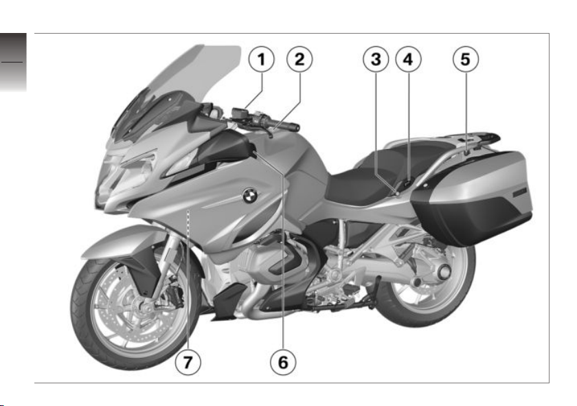
General view, left side
1 Clutch-fluid reservoir
( 154)
2 Fuel filler neck ( 126)
3 Seat lock ( 94)
4 Passenger seat heating
( 92)
5 2nd socket
6 Storage compartment, left
( 97)
7 Payload table
Table of tyre pressures
2
19
z
General views
Page 22
2
20
z
General views
Page 23

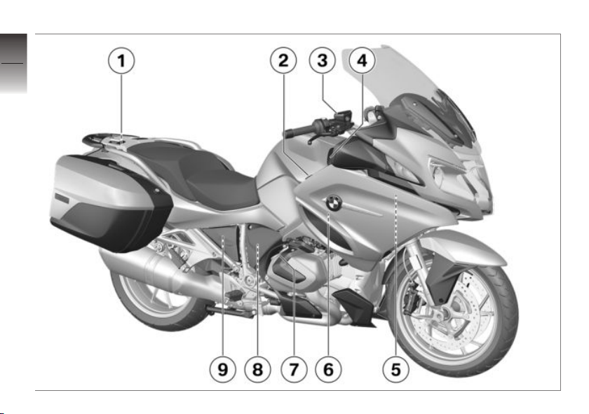
General view, right side
1 Rider's manual
2 Power socket ( 180)
3 Brake-fluid reservoir, front
( 152)
4 Storage compartment, right
( 97)
5 Vehicle identification num-
ber (on the steering-head
bearing)
Type plate (on the
steering-head bearing)
6 Coolant level indicator (be-
hind side panel) ( 154)
7 Oil filler opening ( 148)
8 Behind the engine spoiler:
Battery ( 171)
Remote positive terminal
( 170)
Diagnostic connector
( 176)
9 Brake fluid tank rear (be-
hind the side trim panel)
( 153)
2
21
z
General views
Page 24
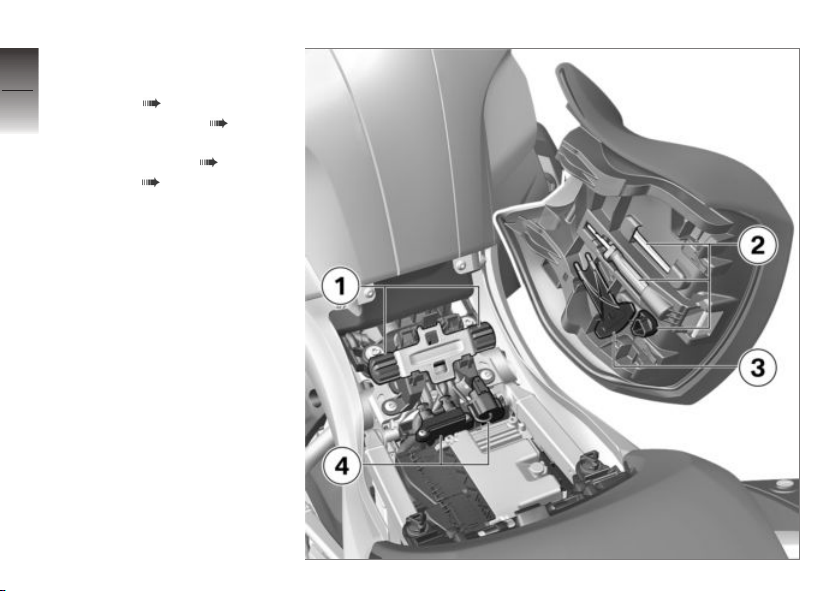
Underneath the seat
2
1 Adjuster for front-seat
22
z
General views
height ( 95)
2 Standard toolkit ( 146)
3 Tool for adjusting the
spring preload ( 109)
4 Fuses ( 175)
Page 25
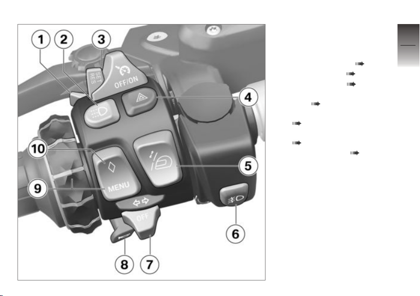
Multifunction switch, left
1 High-beam headlight and
headlight flasher ( 69)
2 Day run lights ( 70)
3 Cruise control ( 83)
4 Hazard warning lights sys-
tem ( 72)
5 Windscreen adjuster
( 104)
6 Additional headlight
( 69)
7 Turn indicators ( 72)
8 Horn
2
23
z
General views
Page 26

9 Multi-Controller and MENU
2
24
z
General views
button
Multifunction display
( 73)
ASC ( 79)
with riding modes Pro
DTC ( 80)
with Dynamic ESA
D-ESA ( 81)
with audio system
Audio system (see relevant
operating instructions)
10 Favourite menu ( 76).
OE
OE
OE
Page 27
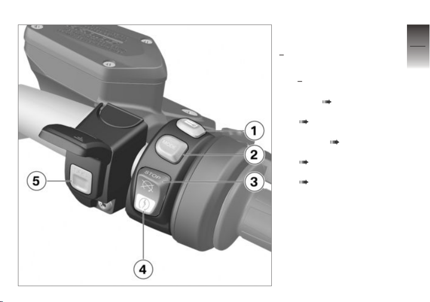
Multifunction switch, right
with intelligent emergency
OE
call
1 with central locking sys-
2 Selecting the riding mode
3 Emergency off switch (kill
4 Starting the engine
5 Intelligent emergency call
OE
tem
Lock ( 98).
( 82)
switch) ( 66)
( 117)
( 66)
2
25
z
General views
Page 28
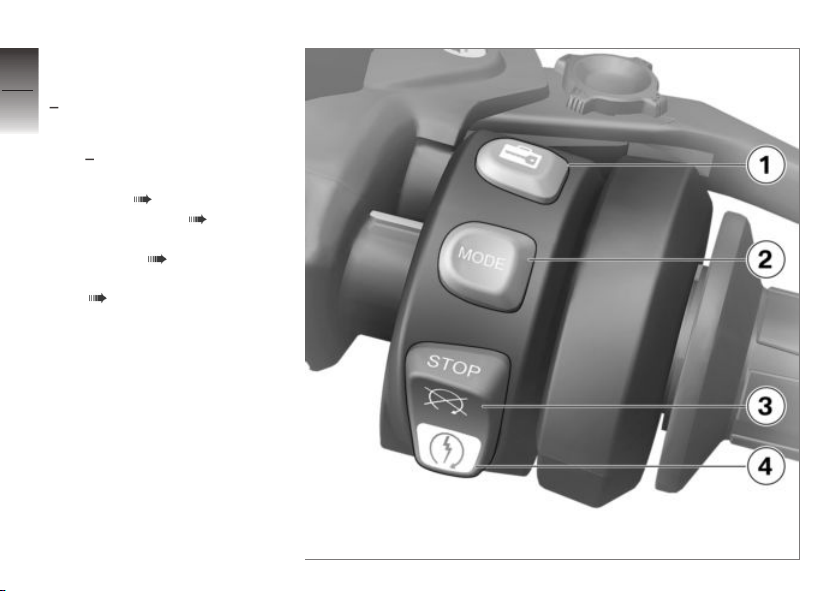
Multifunction switch,
2
right
26
without intelligent emergency
OE
call
1 with central locking sys-
2 Riding mode ( 82)
3 Emergency off switch (kill
4 Starting the engine
z
General views
OE
tem
Lock ( 98).
switch) ( 66)
( 117)
Page 29
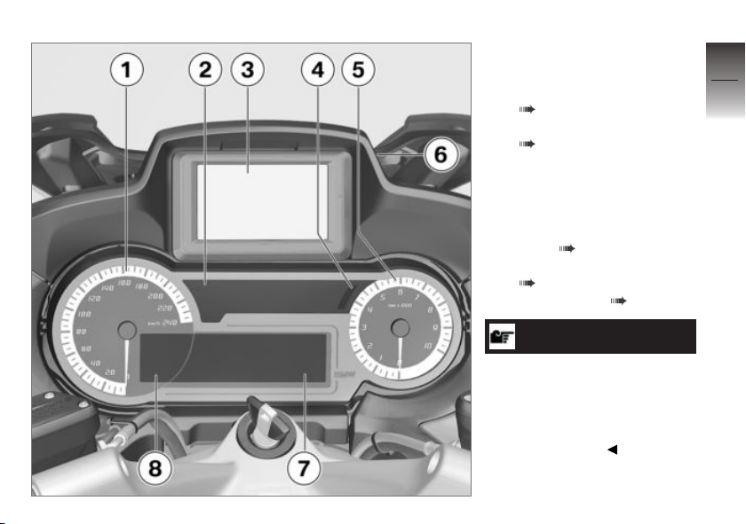
Instrument panel
1 Speedometer
2 Indicator and warning lights
( 30)
3 Navigation system
( 186)
4 Photosensor (for adapting
the brightness of the instrument lighting)
5 Engine speed display
6 Unlocking for navigation
shaft ( 186)
7 Multifunction display
( 33)
8 Trip recorder ( 79)
NOTICE
The brightness of the warning
lights and indicator lights, the
display and the instrument
needle and gauge lighting is
adapted automatically to suit
ambient brightness.
2
27
z
General views
Page 30

2
28
z
General views
Page 31

Status indicators
Indicator and warning lights . . . . . . . . . 30
Meaning of symbols . . . . . . . . . . . . . . . . 31
Multifunction display . . . . . . . . . . . . . . . . 33
Warnings . . . . . . . . . . . . . . . . . . . . . . . . . . . 34
Range . . . . . . . . . . . . . . . . . . . . . . . . . . . . . . 53
Electronic oil-level check . . . . . . . . . . . . 53
Ambient temperature . . . . . . . . . . . . . . . 54
Tyre pressures. . . . . . . . . . . . . . . . . . . . . . 54
3
29
z
Status indicators
Page 32
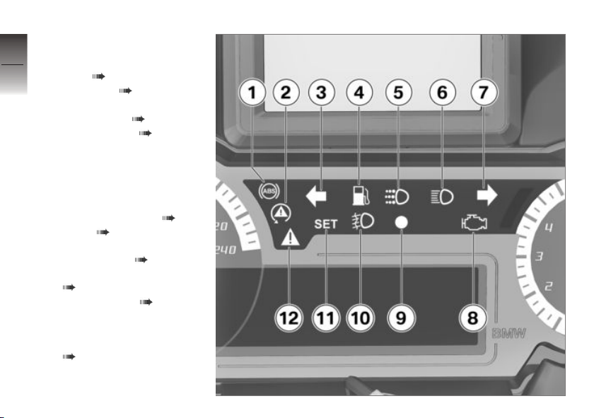
Indicator and warning
3
lights
30
1 ABS ( 47)
2 ASC/DTC ( 48)
3 Turn indicators, left
4 Fuel reserve ( 53)
5 Day run lights ( 70)
6 High-beam
7 Turn indicators, right
8 with export to EU mar-
9 DWA ( 89)
z
Status indicators
10 Additional headlight
11 Cruise control ( 83)
12 General warning light, in
OE
kets
Malfunction indicator lamp
Emissions warning ( 42)
Indicator light for the radiooperated key ( 60)
( 69)
connection with warning
symbols in the display
( 34)
Page 33
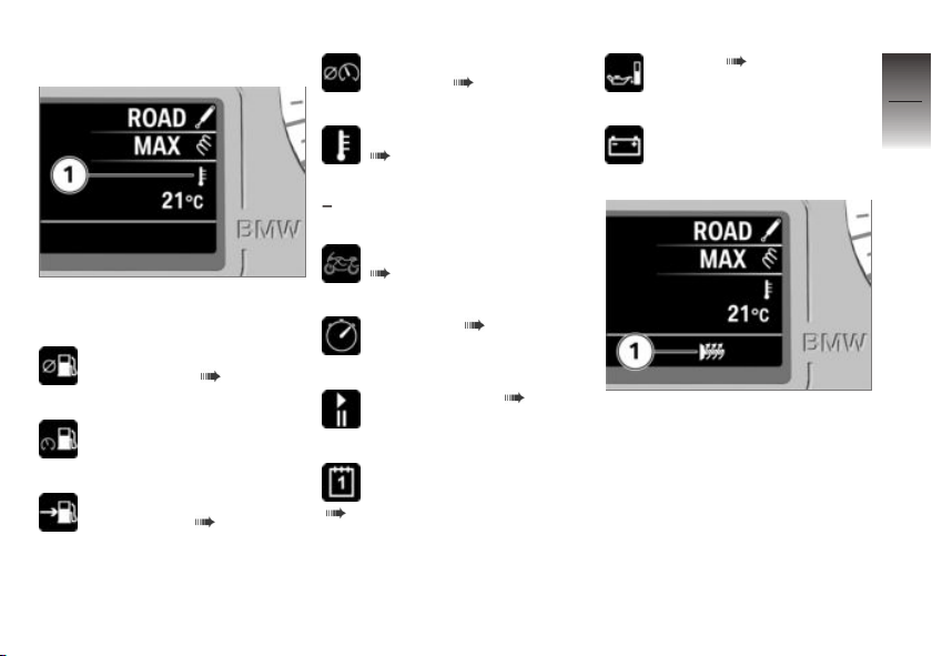
Meaning of symbols
Meaning of the symbols at position 1:
Average consumption since
the last reset ( 78)
Current consumption
Range with the available
fuel quantity ( 53)
Average speed since the
last reset ( 78)
Ambient temperature
( 54)
with tyre pressure control
OE
(RDC)
Tyre inflation pressures
( 54)
Stopwatch ( 78)
Travelling times ( 78)
Date (display depends on
the configured time format)
( 77)
Oil level ( 53)
On-board voltage
1 Heated grips switched on
3
31
z
Status indicators
Page 34
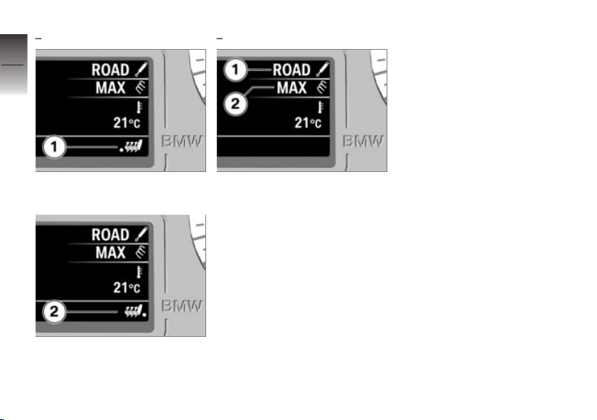
3
32
with seat heating
OE
with Dynamic ESA
OE
1 Rider's seat heating switched
on
z
Status indicators
2 Passenger seat heating
switched on
1 Damping mode
2 Load setting
Page 35
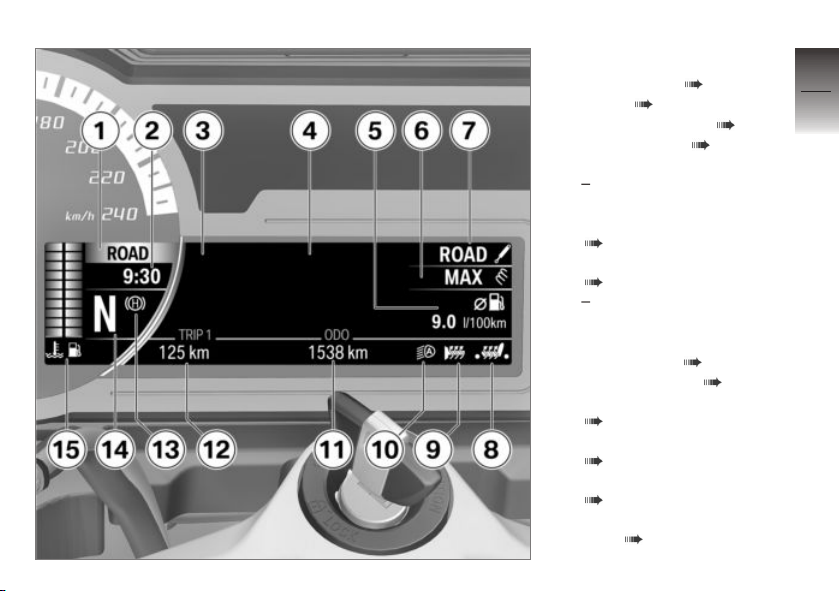
Multifunction display
1 Riding mode ( 82)
2 Clock ( 77)
3 Warning symbols ( 34)
4 Menu section ( 73)
Audio system
with intelligent emer-
gency call
Emergency call display
( 51)
5 On-board computer
( 77)
with tyre pressure control
(RDC)
Tyre pressure
6 Load setting ( 81)
7 Damping mode ( 81)
8 Rider's seat heating
( 92)
Passenger seat heating
( 92)
9 Heated handlebar grips
( 91)
10 Automatic daytime riding
light ( 71)
OE
OE
3
33
z
Status indicators
Page 36
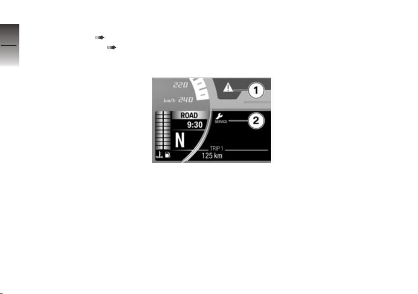
11 Odometer
12 Trip recorder ( 79)
3
13 Hill Start Control ( 85)
34
14 Gear indicator; "N" indic-
ates neutral.
15 Coolant temperature
Fuel level
Warnings
Mode of presentation
Warnings are indicated by the
corresponding warning lights.
The general warning light is displayed according to the most
urgent warning .
The possible warnings are listed
on the following pages.
z
Status indicators
Warnings for which there are
no separate warning lights are
shown using the general warning light 1 in combination with a
warning symbol such as 2 on the
multifunction display. The 'general' warning light is yellow or red,
depending on the urgency of the
warning.
Up to four warning symbols can
be displayed at the same time.
Page 37
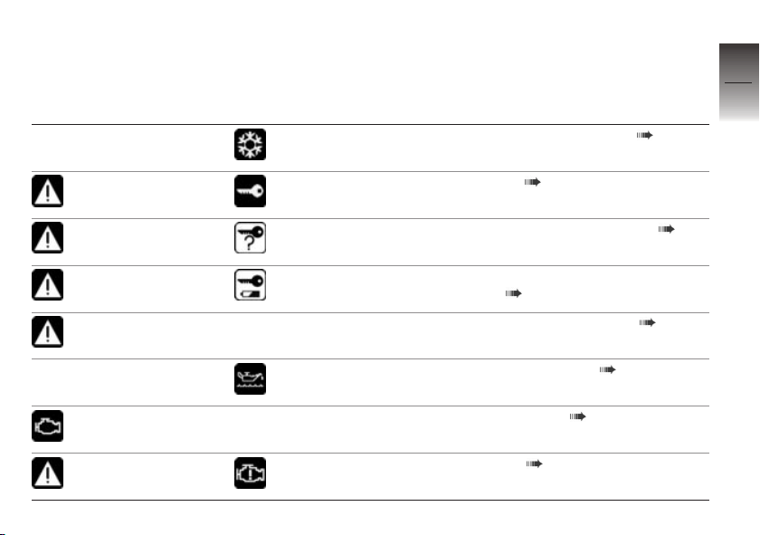
Warnings, overview
Indicator and warning
Display text Meaning
lights
appears on the
display
lights up yellow appears on the
lights up yellow appears on the
lights up yellow appears on the
lights up red Temperature
Malfunction indicator lamp lights up
lights up yellow appears on the
display
display
display
display turns red.
appears on the
display
display
Outside temperature warning ( 40)
EWS active ( 40)
Radio-operated key out of range ( 40)
Replace the battery of the radio-operated key ( 41)
Coolant temperature too high ( 41)
Engine-oil level too low ( 41)
Emissions warning ( 42)
Engine fault ( 42)
3
35
z
Status indicators
Page 38
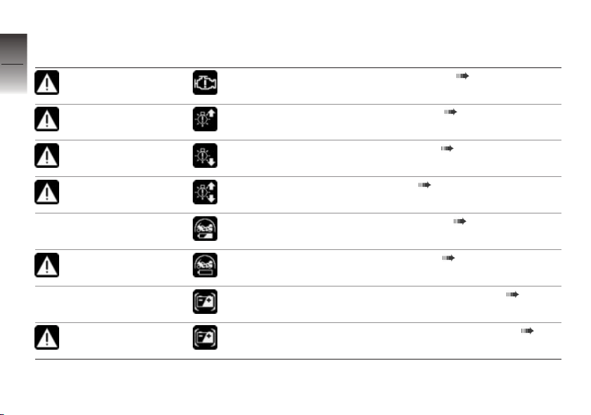
Indicator and warning
3
lights
36
z
Status indicators
flashes yellow
lights up yellow appears on the
lights up yellow appears on the
lights up yellow appears on the
lights up yellow appears on the
lights up yellow appears on the
Display text Meaning
appears on the
display
display
display
display
appears on the
display
display
appears on the
display
display
Severe engine fault ( 42)
Front light failure ( 43)
Rear light failure ( 43)
Light failure ( 43)
DWA battery weak ( 43)
DWA battery flat ( 44)
On-board system voltage low ( 44)
On-board system voltage critical ( 44)
Page 39
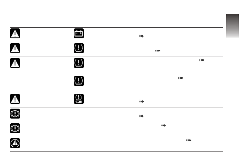
Indicator and warning
Display text Meaning
lights
lights up red appears on the
flashes red
lights up yellow + "––" or "–– ––
lights up yellow appears on the
flashes ABS self-diagnosis not completed
lights up
quick-flashes ASC/DTC intervention ( 48)
display
+ tyre pressure in
red
" appears on the
display
+ "––" or "–– ––
" appears on the
display
display
Battery charge voltage insufficient
( 45)
Tyre pressure outside the permitted tolerance ( 45)
Sensor faulty or system fault ( 46)
Transmission fault ( 46)
Battery for tyre pressure sensor weak
( 47)
( 47)
ABS fault ( 47)
3
37
z
Status indicators
Page 40
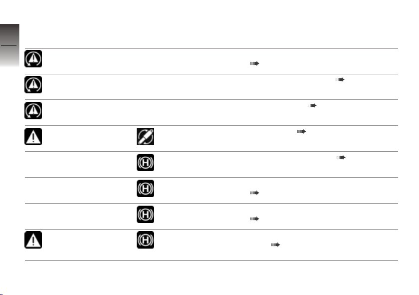
Indicator and warning
3
lights
38
slow-flashes ASC/DTC self-diagnosis not completed
lights up
Display text Meaning
( 48)
ASC/DTC switched off ( 48)
lights up
lights up yellow appears on the
z
Status indicators
flashes yellow
display
Green holding symbol is displayed.
White holding symbol is displayed.
Yellow holding
symbol is displayed.
Yellow holding
symbol flashes
briefly.
ASC/DTC fault ( 48)
DESA fault ( 49)
Hill Start Control active ( 49)
Automatic Hill Start Control Pro active
( 49)
Hill Start Control cannot be activated.
( 49)
Hill Start Control automatically deactivated ( 50)
Page 41
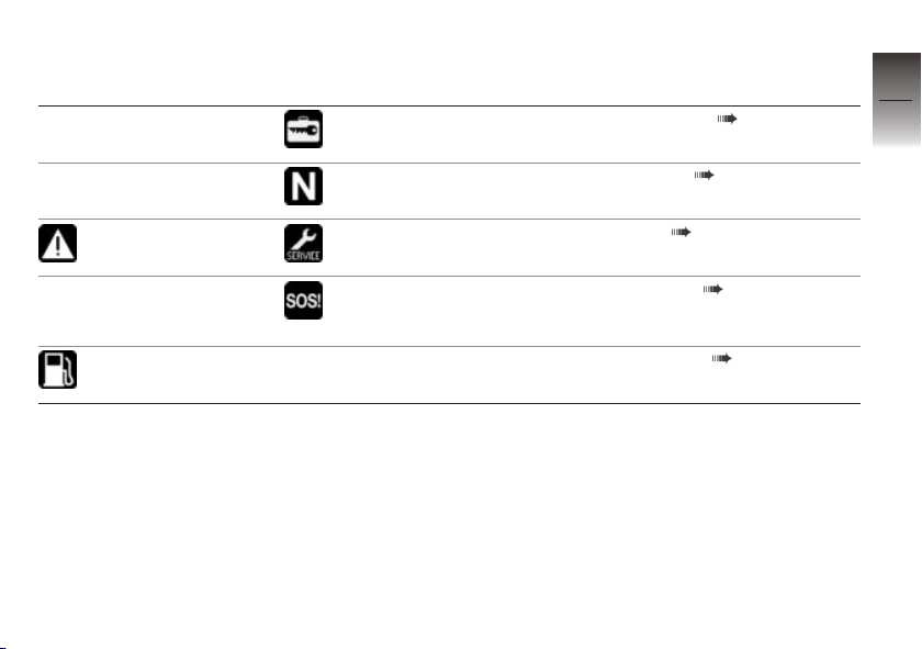
Indicator and warning
Display text Meaning
lights
appears on the
display
The gear indicator
flashes.
briefly shows yellow
lights up Fuel-level reading
appears on the
display
The symbol for an
emergency call error is displayed.
turns yellow
Central locking locked ( 50)
Gear not calibrated ( 50)
Service overdue ( 51)
Emergency call fault ( 52)
Fuel down to reserve ( 53)
3
39
z
Status indicators
Page 42
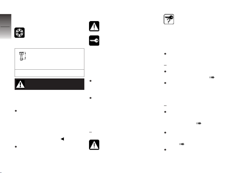
Outside temperature
3
warning
40
z
Status indicators
appears on the display.
Possible cause:
The air temperature
measured at the vehicle
is lower than:
approx. 3 °C
WARNING
Risk of black ice also applicable at over 3 °C
Risk of accident
Always take extra care
when temperatures are
low; remember that there is
particular danger of black ice
forming on bridges and where
the road is in shade.
Ride carefully and think well
ahead.
EWS active
lights up yellow.
appears on the display.
Possible cause:
The key being used is not au-
thorised for starting, or communication between key and engine
electronics is disrupted.
Remove all other vehicle keys
from the same ring as the ignition key.
Have the defective key replaced, preferably by an authorised BMW Motorrad dealer.
Radio-operated key out of
range
with Keyless Ride
lights up yellow.
OE
appears on the display.
Possible cause:
Communication between R/C key
and engine electronics is disrupted.
Check the battery in the radiooperated key.
with Keyless Ride
Replace the battery of the
radio-operated key ( 65).
Use the emergency key or the
radio-operated key with the
empty battery to continue your
journey.
with Keyless Ride
Battery of the radio-operated
key is empty, emergency key is
not available ( 63).
Loss of the radio-operated
key, emergency key is available ( 63).
Remain calm if the warning
symbol appears while you are
OE
OE
Page 43
riding. You can continue your
journey, the engine will not
switch off.
Have the defective radio-operated key replaced by an authorised BMW Motorrad dealer.
Replace the battery of the
radio-operated key
lights up yellow.
The battery symbol appears
on the display.
Possible cause:
The integral battery in the
radio-operated key has lost
a significant proportion of its
original capacity. There is no
assurance of how long the R/C
key can remain operational.
with Keyless Ride
Replace the battery of the
radio-operated key ( 65).
OE
Coolant temperature too
high
lights up red.
The temperature reading turns
red.
ATTENTION
Riding with overheated engine
Engine damage
Compliance with the
information set out below is
essential.
Possible cause:
The coolant temperature is too
high.
If possible, ride in the part-load
range to cool down the engine.
If the coolant temperature
is frequently too high, have
the fault rectified as soon
as possible by a specialist
workshop, preferably an
authorised BMW Motorrad
dealer.
Engine-oil level too low
appears on the display.
Possible cause:
The electronic oil-level sensor
has registered a low oil level. If
the vehicle is not standing upright on a smooth, level surface,
the message might appear even
though the oil level is correct.
The next time you stop for fuel:
Checking engine oil level
( 148).
If the oil level in the sight glass is
too low:
Topping up the engine oil
( 149).
When the oil level in the sight
glass is correct:
Check whether the precondi-
tions for the electronic oil-level
check are met.
3
41
z
Status indicators
Page 44
If the message appears
repeatedly, even though the
3
oil level is slightly below the
42
maximum mark:
Seek the advice of a specialist
workshop, preferably an authorised BMW Motorrad dealer.
Emissions warning
Malfunction indicator lamp
lights up
Possible cause:
The engine control unit has dia-
gnosed a fault which affects the
pollutant emissions.
z
Status indicators
Have the fault rectified by a
specialist workshop, preferably
an authorised BMW Motorrad
dealer.
You can continue riding; pollutant emissions are higher than
the threshold values.
Engine fault
lights up yellow.
appears on the display.
Possible cause:
The engine control unit has dia-
gnosed a fault.
WARNING
Unusual ride characteristics when engine running in
emergency-operation mode
Risk of accident
Avoid accelerating sharply and
overtaking.
If you continue to ride be prepared for unusual engine behaviour (low power, poor throttle
response, abrupt stalling, etc.).
Have the fault rectified as
quickly as possible by a
specialist workshop, preferably
an authorised BMW Motorrad
dealer.
Severe engine fault
flashes yellow.
appears on the display.
Possible cause:
The engine control unit has dia-
gnosed a severe fault.
WARNING
Engine damage when run-
ning in emergency-operation
mode
Risk of accident
Ride slowly, avoid accelerating
sharply and overtaking.
If possible, have the vehicle
picked up and have the fault
rectified by a specialist workshop, preferably an authorised
BMW Motorrad Retailer.
Page 45
If you continue to ride be prepared for unusual engine behaviour (low power, poor throttle
response, abrupt stalling, etc.).
Have the fault rectified as
quickly as possible by a
specialist workshop, preferably
an authorised BMW Motorrad
dealer.
Front light failure
lights up yellow.
appears on the display.
Possible cause:
Low-beam headlight, high-beam
headlight, side light or front turn
indicator faulty.
The low-beam headlight or one
of the LED flashing turn indicators has to be replaced.
Consult a specialist workshop,
preferably an authorised
BMW Motorrad Retailer.
Rear light failure
lights up yellow.
appears on the display.
Possible cause:
Rear light, brake light or rear
flashing turn indicator defective.
The LED rear light must be replaced.
Consult a specialist workshop,
preferably an authorised
BMW Motorrad dealer.
Light failure
lights up yellow.
appears on the display.
Possible cause:
A combination of light failures
has occurred.
Consult a specialist workshop,
preferably an authorised
BMW Motorrad dealer.
DWA battery weak
with anti-theft alarm (DWA)
appears on the display.
NOTICE
This error message shows briefly
only after the Pre-Ride-Check
completes.
Possible cause:
The integral battery in the anti-
theft alarm (DWA) has lost a significant proportion of its original
capacity. There is no assurance
of how long the DWA anti-theft
alarm can remain operational if
the vehicle's battery is disconnected.
OE
3
43
z
Status indicators
Page 46
Seek the advice of a specialist
workshop, preferably an author-
3
ised BMW Motorrad dealer.
44
DWA battery flat
with anti-theft alarm (DWA)
lights up yellow.
appears on the display.
NOTICE
This error message shows briefly
only after the Pre-Ride-Check
z
Status indicators
completes.
Possible cause:
The integral battery in the anti-
theft alarm (DWA) has lost its entire original capacity. There is no
assurance that the DWA antitheft alarm will be operational if
the vehicle's battery is disconnected.
Seek the advice of a specialist
workshop, preferably an authorised BMW Motorrad dealer.
On-board system voltage
OE
low
appears on the display.
Generator power is only just
sufficient to supply all consumers
and charge the battery.
Possible cause:
Too many consumers switched
on. On-board system voltage
tends to drop particularly at low
engine rpm and when the engine
is idling.
When riding at low engine
rpm switch off all consumers
that are not necessary for
road safety (e.g. heated body
warmer or auxiliary headlights).
On-board system voltage
critical
lights up yellow.
appears on the display.
Generator power is no longer
sufficient to supply all consumers
and charge the battery. In order
to ensure that the engine can
be started and the motorcycle
ridden, the on-board electronics
switch off the electricity supply
to the on-board sockets and the
auxiliary headlights. In extreme
cases the seat heating and the
grip heating might also be shut
down.
Possible cause:
Too many consumers switched
on. On-board system voltage
tends to drop particularly at low
engine rpm and when the engine
is idling.
Page 47
When riding at low engine
rpm switch off all consumers
that are not necessary for
road safety (e.g. heated body
warmer or auxiliary headlights).
Battery charge voltage
insufficient
lights up red.
appears on the display.
WARNING
Failure of the vehicle systems
Risk of accident
Do not continue your journey.
Battery is not being charged. If
you continue to ride the vehicle
the on-board electronics will
drain the battery.
Possible cause:
Alternator or alternator drive
faulty or fuse for alternator
regulator has blown.
Have the fault rectified as
quickly as possible by a
specialist workshop, preferably
an authorised BMW Motorrad
dealer.
Tyre pressure outside the
permitted tolerance
with tyre pressure control
OE
(RDC)
flashes red.
+ the critical tyre pressure
shows red.
Possible cause:
Measured tyre pressure is out-
side permitted tolerance.
Check the tyre for damage
and to ascertain whether the
vehicle can be ridden with the
tyre in its present condition.
If the vehicle can be ridden with
the tyre in its present condition:
Correct the tyre pressure at the
earliest possible opportunity.
NOTICE
Before adjusting the tyre pressure, observe the information
on temperature compensation
and pressure adaptation in the
section entitled "Engineering
details":
Have the tyre checked for
damage by a specialist
workshop, preferably an
authorised BMW Motorrad
dealer.
If you are unsure whether the
vehicle can be ridden with the
tyre in its present condition:
Do not continue your journey.
Notify the breakdown service.
3
45
z
Status indicators
Page 48
Sensor faulty or system
3
fault
with tyre pressure control
46
z
Status indicators
OE
(RDC)
lights up yellow.
+ "--" or "-- --" appears
on the display.
Possible cause:
Motorcycle is fitted with wheels
not equipped with RDC sensors.
Fit wheels and tyres equipped
with RDC sensors.
Possible cause:
1 or 2 RDC sensors have failed
or a system error has occurred.
Have the fault rectified by a
specialist workshop, preferably
an authorised BMW Motorrad
dealer.
Possible cause:
A system error has occurred.
Have the fault rectified by a
specialist workshop, preferably
an authorised BMW Motorrad
dealer.
Transmission fault
with tyre pressure control
OE
(RDC)
+ "--" or "-- --" appears
on the display.
Possible cause:
The vehicle did not reach
the minimum required speed
( 140).
RDC sensor is not active
min 30 km/h (The RDC sensor
does not transmit its signal
to the vehicle until a certain
minimum speed has been
reached.)
Increase speed above this
threshold and observe the RDC
readings. Assume that a permanent fault has not occurred
unless the 'General' warning
light comes on to accompany
the symptoms. Under these
circumstances:
Have the fault rectified by a
specialist workshop, preferably
an authorised BMW Motorrad
dealer.
Possible cause:
Wireless communication with the
RDC sensors has been disrupted.
Possible causes include radio-
communication systems operat-
ing in the vicinity and interfering
with the link between the RDC
control unit and the sensors.
Move to another location and
observe the RDC readings. Assume that a permanent fault
has not occurred unless the
'General' warning light comes
Page 49
on to accompany the symptoms. Under these circumstances:
Have the fault rectified by a
specialist workshop, preferably
an authorised BMW Motorrad
dealer.
Battery for tyre pressure
sensor weak
with tyre pressure control
OE
(RDC)
lights up yellow.
appears on the display.
NOTICE
This error message shows briefly
only after the Pre-Ride-Check
completes.
Possible cause:
The integral battery in the tyre-
pressure sensor has lost a significant proportion of its original
capacity. There is no assurance
of how long the tyre pressure
control system can remain operational.
Seek the advice of a specialist
workshop, preferably an authorised BMW Motorrad dealer.
ABS self-diagnosis not
completed
flashes.
Possible cause:
ABS self-diagnosis not
completed
The ABS function is not available, because self-diagnosis
did not complete. (The motorcycle has to reach a defined
minimum speed for the wheel
speed sensors to be checked:
5 km/h)
Pull away slowly. Bear in mind
that the ABS function is not
available until self-diagnosis has
completed.
ABS fault
lights up.
Possible cause:
The ABS control unit has detec-
ted a fault. The partially integral
brake and the Dynamic Brake
Control function have failed. The
ABS function is not available.
3
47
z
Status indicators
Page 50
It is possible to continue riding
taking the failed ABS function
3
into consideration. Take note
48
of the further information on
situations that may lead to an
ABS fault ( 133).
Have the fault rectified as
quickly as possible by a
specialist workshop, preferably
an authorised BMW Motorrad
Retailer.
ASC/DTC intervention
quick-flashes.
The ASC/DTC has detec-
ted a degree of instability at the
z
Status indicators
rear wheel and has intervened to
reduce torque. The indicator and
warning light flashes for longer
than ASC/DTC intervention lasts.
This affords the rider visual feedback on control intervention even
after the critical situation has
been dealt with.
ASC/DTC self-diagnosis
not completed
slow-flashes.
Possible cause:
ASC/DTC self-diagnosis
not completed
The ASC/DTC function is
not available, because selfdiagnosis did not complete.
(The motorcycle has to reach
a defined minimum speed
for the wheel sensors to be
checked: min 5 km/h)
Pull away slowly. Bear in mind
that the ASC/DTC function is
not available until self-diagnosis
has completed.
ASC/DTC switched off
lights up.
Possible cause:
The rider has switched off the
ASC/DTC system.
Switch on ASC/DTC.
ASC/DTC fault
lights up.
Possible cause:
The ASC/DTC control unit has
detected a fault. The ASC/DTC
function is not available.
You can continue to ride. Bear
in mind that the ASC/DTC
function is not available. Take
note of the more detailed information on situations that
can lead to a ASC/DTC fault
( 136).
Have the fault rectified as
quickly as possible by a
specialist workshop, preferably
an authorised BMW Motorrad
Retailer.
Page 51
DESA fault
lights up yellow.
appears on the display.
Possible cause:
The DESA control unit has de-
tected a fault. The damping and/
or spring adjuster may be the
cause. In Auto the cause may
also be a fault in the riding position equaliser. In this condition,
the motorcycle may have too
much damping and is uncomfortable to drive, especially on
roads in poor condition. Alternatively, the spring setting may be
set incorrectly.
Have the fault rectified as
quickly as possible by a
specialist workshop, preferably
an authorised BMW Motorrad
Retailer.
Hill Start Control active
Green holding symbol is
displayed.
Possible cause:
Hill Start Control ( 143) has
been activated automatically or
activated by the rider.
Operate Hill Start Control
( 85).
with riding modes Pro
Switching automatic Hill Start
Control Pro on and off ( 88).
OE
Automatic Hill Start
Control Pro active
with riding modes Pro
White holding symbol is
displayed.
Possible cause:
The automatic Hill Start Control
Pro is active. If the motorcycle
stops on an incline of > 5%, the
OE
motorcycle is automatically held
in place by the brakes.
Switch off automatic Hill Start
Control Pro.
Switching automatic Hill Start
Control Pro on and off ( 88).
Hill Start Control cannot
be activated
Yellow holding symbol is
displayed.
Possible cause:
Hill Start Control cannot be activ-
ated.
Fold in side stand.
Hill Start Control functions only
when the side stands are fol-
ded in.
Start the engine.
Hill Start Control functions only
when the engine is running.
3
49
z
Status indicators
Page 52
Hill Start Control
3
automatically deactivated
50
z
Status indicators
flashes yellow.
Yellow holding symbol
flashes briefly.
Possible cause:
Hill Start Control has been auto-
matically deactivated.
Side stand has been folded
out.
Hill Start Control is deactivated
when the side stand is folded
out.
Engine has been switched off.
Hill Start Control is deactivated
when the engine is switched
off.
Operate Hill Start Control
( 85).
Central locking locked
with central locking system
The locked symbol appears
on the display.
All locks in the central locking
system are locked.
OE
Gear not calibrated
with shift assistant Pro
The gear indicator flashes.
The shift assistant Pro is
not available.
Possible cause:
with shift assistant Pro
The transmission sensor has not
been completely calibrated.
Engage idle position N and run
the engine at standstill for a
minimum of 10 seconds to calibrate the idle position.
Use clutch control to engage
all gears and ride for a minimum of 10 seconds in each
engaged gear.
OE
OE
The gear indicator stops
flashing once the transmission
sensor has been successfully
calibrated.
Once the transmission sensor
has been completely calibrated,
shift assistant Pro will operate
as described ( 141).
If the calibration process was
unsuccessful, have the fault
eliminated by a specialist
workshop, we recommend a
BMW Motorrad Partner.
Service-due indicator
If a service is due, the
service symbol and the
service date in place of the total
distance are briefly displayed
subsequent to the Pre-RideCheck.
If the service is overdue
the 'General' warning light
briefly shows yellow and the
service symbol lights up and remains ON.
Page 53
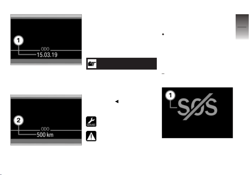
If the countdown to the next
service is less than one month,
the service-due date 1 appears
on the display.
If the vehicle covers long distances in the course of the year,
under certain circumstances it
might be necessary to have it
serviced at a date in advance
of the forecast due date. If the
countdown distance to the early
service is less than 1000 km, the
countdown distance 2 appears
on the display.
NOTICE
If the service-due indicator appears more than a month before
the service date, the current date
has to be corrected. This situation can occur if the battery was
disconnected.
Service overdue
appears on the display.
General warning light briefly
shows yellow after the Pre-
Ride-Check.
Possible cause:
A necessary service has not
been carried out.
Have servicing carried out as
quickly as possible by a specialist workshop, preferably
an authorised BMW Motorrad
dealer.
Emergency call display
with intelligent emergency
OE
call
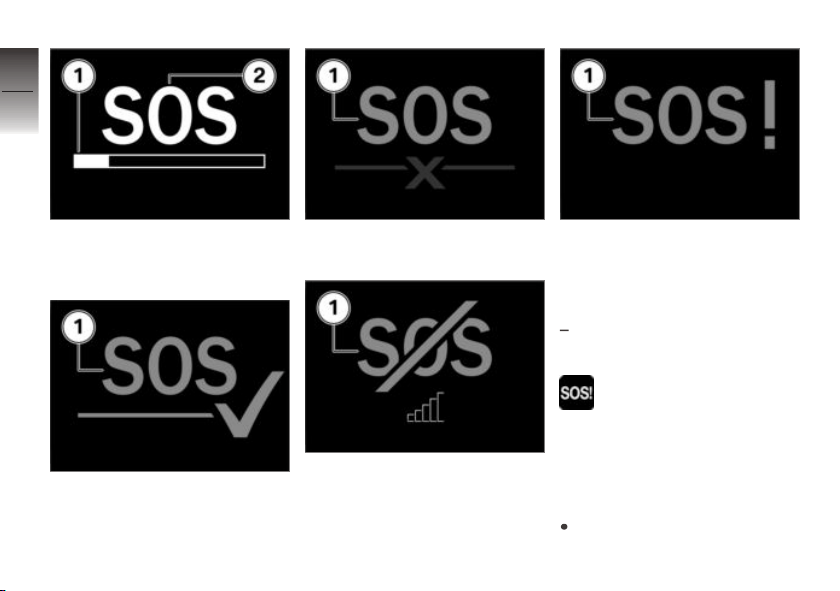
If a manual emergency call is
triggered by the rider during riding, the emergency call symbol 1
is displayed.
3
51
z
Status indicators
Page 54
3
52
During the connection setup, a
progress bar 1 is displayed under
the emergency call symbol 2.
z
Status indicators
If a connection has been established, the symbol 1 is displayed.
If no connection could be established, the symbol 1 is displayed.
If there is no mobile phone reception, the symbol 1 is displayed.
If no emergency call is possible
due to a technical failure, the
symbol 1 is displayed.
Emergency call fault
with intelligent emergency
OE
call
The symbol for an
emergency call error is
displayed.
Possible cause:
The control unit for emergency
call has detected a fault. No
emergency call is possible.
Have the fault rectified as
quickly as possible by a
Page 55
specialist workshop, preferably
an authorised BMW Motorrad
dealer.
Fuel down to reserve
lights up.
Fuel-level reading turns yellow.
WARNING
Irregular engine operation or
engine shutdown due to lack
of fuel
Risk of accident, damage to catalytic converter
Do not run the fuel tank dry.
Possible cause:
The fuel tank contains no more
than the reserve quantity of fuel.
Reserve fuel
approx. 4 l
Refuelling ( 126).
Range
The range readout indic-
ates how far you can ride
with the fuel remaining in the
tank. The figure for average consumption used to calculate range
is not shown and might not be
the same as the average-consumption reading that appears on
the display.
You must put at least five litres of
fuel into the fuel tank for the new
level to be registered correctly.
If the sensor cannot register the
new level the range readout cannot be updated.
When the motorcycle is propped
on its side stand the slight angle
of inclination means that the
sensor cannot register the fuel
level correctly. This is the reason
why the range is calculated only
when the side stand is in the retracted position.
NOTICE
The calculated range is only
an approximate figure. Consequently, BMW Motorrad recommends that you should not
try to use the full range before
refuelling.
Electronic oil-level check
The electronic oil-level
check provides information
about the oil level in the engine.
The preconditions for the electronic oil-level check are as follows:
Engine at operating temperature.
Engine idling for at least ten
seconds.
No brake applied.
Side stand folded in.
3
53
z
Status indicators
Page 56
Motorbike standing upright.
3
The readings mean:
54
OK: oil level is correct.
CHECK!: check the oil level the
next time you stop for fuel.
– – –: oil level cannot be measured (conditions as stated above
not satisfied).
Ambient temperature
When the motorcycle is at
z
Status indicators
a standstill the heat of the
engine can falsify the ambienttemperature reading. If the effect
of the engine's heat becomes excessive, "--" temporarily appears
on the display.
If ambient temperature
drops below the threshold
this warning appears, drawing
your attention to the risk of black
ice forming. The display automatically switches from any other
mode to the temperature reading when the temperature drops
below this threshold for the first
time.
Threshold for ambient
temperature
approx. 3 °C
Tyre pressures
with tyre pressure control
OE
(RDC)
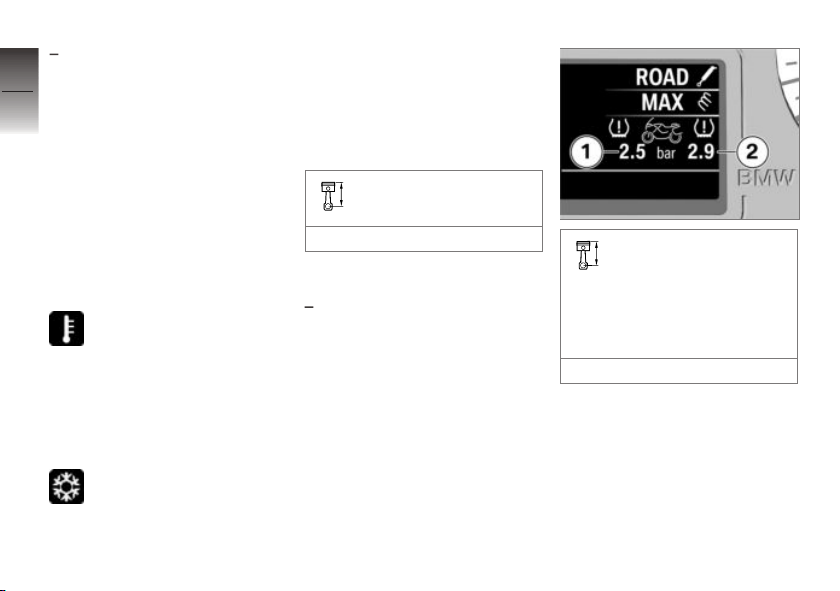
The tyre-pressure read-
ings in the multifunction
display are temperature-compensated and are always referenced to the following tyre-air
temperature:
20 °C
The left value 1 indicates the
filling pressure of the front wheel;
the right value 2 indicates the
filling pressure of the rear wheel.
Immediately after the ignition is
switched on "-- --" is displayed.
Page 57
RDC sensor is not active
min 30 km/h (The RDC sensor
does not transmit its signal
to the vehicle until a certain
minimum speed has been
reached.)
In the event of a critical tyre inflation pressure, the relevant display
appears red.
The tyre warning symbol is
also displayed.
The general warning light
flashes red.
You can find further information
about BMW Motorrad RDC from
page ( 140).
3
55
z
Status indicators
Page 58

3
56
z
Status indicators
Page 59

Operation
Ignition switch/steering lock . . . . . . . . . 58
Ignition with Keyless Ride . . . . . . . . . . . 60
Emergency off switch (kill
switch) . . . . . . . . . . . . . . . . . . . . . . . . . . . . . . 66
Intelligent emergency call . . . . . . . . . . . 66
Lights . . . . . . . . . . . . . . . . . . . . . . . . . . . . . . . 69
Day run lights . . . . . . . . . . . . . . . . . . . . . . . 70
Hazard warning lights system . . . . . . . 72
Turn indicators . . . . . . . . . . . . . . . . . . . . . . 72
Multifunction display . . . . . . . . . . . . . . . . 73
On-board computer. . . . . . . . . . . . . . . . . 77
Trip recorder . . . . . . . . . . . . . . . . . . . . . . . . 79
Automatic Stability Control
(ASC) . . . . . . . . . . . . . . . . . . . . . . . . . . . . . . . 79
Dynamic Traction Control (DTC) . . . . 80
Electronic Suspension Adjustment
(DESA) . . . . . . . . . . . . . . . . . . . . . . . . . . . . . 81
Riding mode . . . . . . . . . . . . . . . . . . . . . . . . 82
Cruise-control system . . . . . . . . . . . . . . 83
Hill Start Control . . . . . . . . . . . . . . . . . . . . 85
Anti-theft alarm (DWA) . . . . . . . . . . . . . . 88
Heating . . . . . . . . . . . . . . . . . . . . . . . . . . . . . 91
Front seat. . . . . . . . . . . . . . . . . . . . . . . . . . . 94
Rear seat . . . . . . . . . . . . . . . . . . . . . . . . . . . 95
Stowage compartment . . . . . . . . . . . . . 97
Central locking system . . . . . . . . . . . . . . 98
4
57
z
Operation
Page 60
Ignition switch/steering
4
lock
58
Keys
You receive 2 ignition keys.
Consult the information on the
electronic immobiliser (EWS)
( 59) if a key is lost or mislaid.
One-key system
Ignition switch/steering lock
Cases locks
z
Operation
Stowage-compartment lock
Tank filler cap
Seat lock
Stowage compartment
with topcase
Topcase
with audio system
Audio compartment
OA
OE
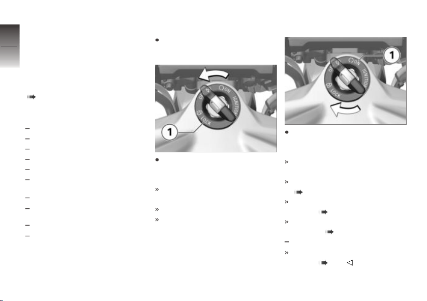
Lock the handlebars
Turn the handlebars all the way
to left.
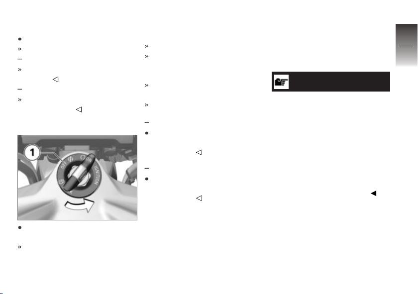
Turn the key to position 1,
while moving the handlebars
slightly.
Ignition, lights and all function
circuits switched off.
Handlebars are locked.
Key can be removed.
Switching on ignition
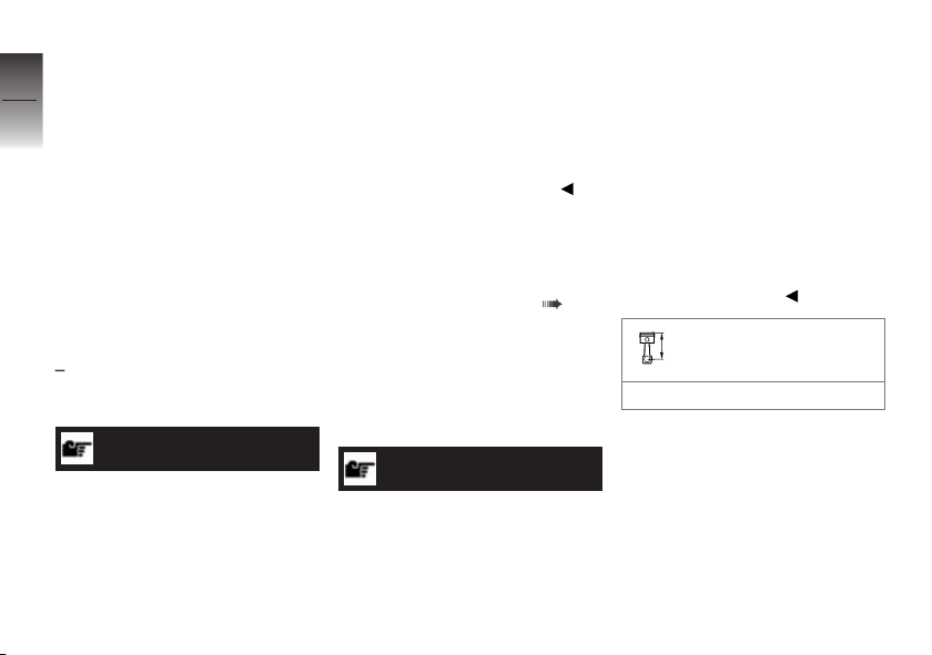
Insert the key into the ignition
steering lock and turn it to position 1.
Side lights and all function circuits are switched on.
Pre-Ride-Check is performed.
( 117)
ABS self-diagnosis is in progress. ( 118)
ASC self-diagnosis is performed. ( 119)
with riding modes Pro
DTC self-diagnosis is in progress. ( 119)
OE
Page 61
Welcome lights
Switch on the ignition.
The side lights briefly light up.
with daytime riding light
The daytime riding lights briefly
light up.
with additional headlight
The LED auxiliary headlights
briefly light up.
OE
OE
Switching off ignition
Turn the ignition key to position 1.
When the ignition is switched
off, the instrument cluster remains switched on for a short
time and displays any existing
fault messages.
Handlebars not locked.
Electrically powered accessories remain operational for a limited period of time.
The battery can be recharged
via the socket.
Key can be removed.
with daytime riding light
The daytime riding light goes
out soon after the ignition is
switched off.
with additional headlight
The LED auxiliary headlights
go out soon after the ignition is
switched off.
OE
OE
Electronic immobiliser
EWS
The electronic design of the
motorcycle allows it to access
data stored in the ignition key
by means of a ring antenna loc-
ated in the ignition switch/steering lock. The engine control unit
will not permit the engine to be
started unless the key is identified as “authorised”.
NOTICE
A spare key attached to the
same ring as the ignition key
used to start the engine could
"irritate" the electronics, in
which case the enabling signal
for starting is not issued. The
warning is displayed on the
multifunction display with the key
symbol.
Always keep the spare key separately from the ignition key.
If you lose a key, you can have
it barred by your authorised
BMW Motorrad dealer.
If you wish to do this, you will
need to bring all other keys for
the motorcycle with you. The
engine cannot be started by a
4
59
z
Operation
Page 62
barred key, but a key that has
been barred can subsequently be
4
reactivated.
60
You can obtain extra keys
only through an authorised
BMW Motorrad dealer. The
keys are part of an integrated
security system, so the dealer is
under an obligation to check the
legitimacy of all applications for
replacement/extra keys.
z
Operation
Ignition with Keyless Ride
with Keyless Ride
Keys
NOTICE
The telltale light for the radiooperated key flashes while the
search for the radio-operated key
is in progress.
OE
The telltale light goes out as
soon as the radio-operated key
or the emergency key is found.
The telltale light goes out briefly
if the search times out without
the radio-operated key or the
emergency key being found.
You receive one radio-operated
key and one emergency key.
Please consult the information on
the electronic immobiliser (EWS)
if a key is lost or mislaid ( 59).
Ignition, fuel filler cap and antitheft alarm system all work with
the radio-operated key. Seat
lock, stowage compartment, topcase and cases can be locked
and unlocked manually.
NOTICE
The vehicle cannot be started or
the central locking system locked
or unlocked if the radio-operated
key is not within range (e.g. key
inside one of the cases or the
topcase).
If the key is taken out of range
the ignition is switched off after
approximately 1.5 minutes, but
the central locking system is not
locked.
It is advisable to keep the radiooperated key on your person
(e.g. in a jacket pocket) and to
have the emergency key with
you as an alternative.
Range of the Keyless
Ride radio-operated key
approx. 1 m
Lock the handlebars
Requirement
The handlebars are turned towards the left.Radio-operated key
is within range.
Page 63
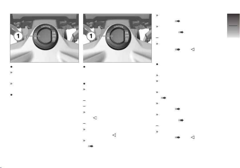
Press and hold down button 1.
The steering lock engages with
an audible click.
Ignition, lights and all function
circuits switched off.
Briefly press the 1 button to
unlock the steering lock.
Switching on ignition
Requirement
Radio-operated key is within
range.
There are two ways of activating the ignition.
Version 1:
Briefly press button 1.
Side lights and all function circuits are switched on.
with daytime riding light
with Headlight Pro
Daytime riding light is switched
on.
with additional headlight
LED auxiliary headlights are
switched on.
Pre-Ride-Check is performed.
( 117)
OE
OE
OE
ABS self-diagnosis is in progress. ( 118)
ASC self-diagnosis is performed. ( 119)
with riding modes Pro
DTC self-diagnosis is in progress. ( 119)
Version 2:
Steering lock is engaged; press
and hold down button 1.
The steering lock disengages.
Parking lights and all function
circuits switched on.
Pre-Ride-Check is performed.
( 117)
ABS self-diagnosis is in progress. ( 118)
ASC self-diagnosis is performed. ( 119)
with riding modes Pro
DTC self-diagnosis is in progress. ( 119)
OE
OE
4
61
z
Operation
Page 64
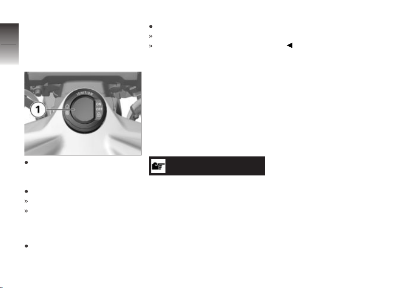
Switching off ignition
4
Requirement
Radio-operated key is within
62
range.
z
Operation
There are two ways of deactivating the ignition.
Version 1:
Short-press button 1.
Light is switched off.
Handlebars (steering lock) are
not locked.
Version 2:
Turn the handlebars all the way
to left.
Press and hold down button 1.
Light is switched off.
The steering lock engages.
Electronic immobiliser
EWS
The on-board electronics access
the data saved in the radio-operated key via a ring aerial in the
R/C ignition lock. The ignition is
not enabled for starting until the
engine control unit has recognised the radio-operated key as
"authorised" for your motorcycle.
NOTICE
A spare key attached to the
same ring as the radio-operated
key used to start the engine
could impair the electronics
function, in which case the
enabling signal for starting is not
issued. The warning is displayed
on the multifunction display with
the key symbol.
Always keep the spare key separate from the radio-operated
key.
If you mislay a radio-operated key
you can have the key in question barred by your authorised
BMW Motorrad dealer. In order
to have a key barred you must
bring along all the other keys belonging to the motorcycle.
The engine cannot be started
by a barred radio-operated key,
but a radio-operated key that has
been barred can subsequently be
reactivated.
You can obtain emergency/extra keys only through an authorised BMW Motorrad dealer. The
radio-operated keys are part of
an integrated security system, so
the dealer is under an obligation
to check the legitimacy of all applications for replacement/extra
keys.
Page 65
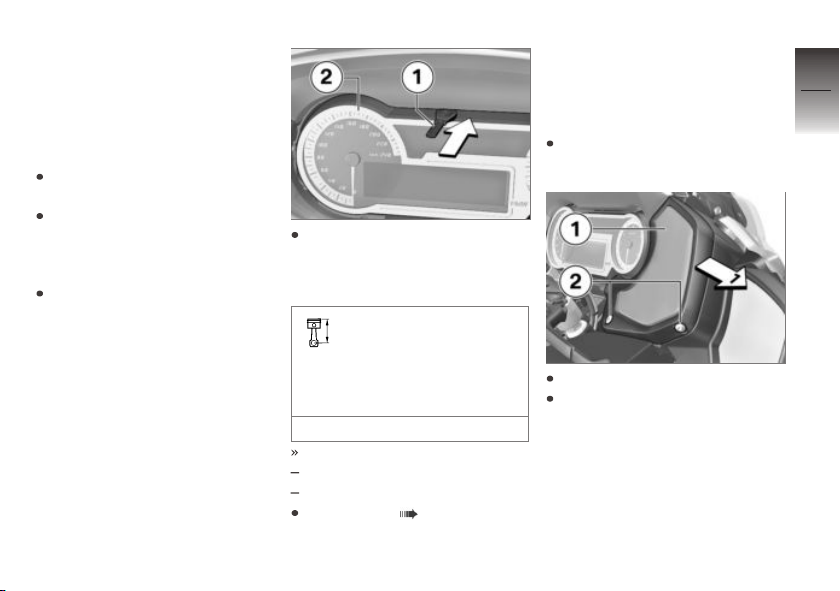
Loss of the radiooperated key, emergency
key is available
Requirement
Emergency key is available.
Place the motorcycle on its
stand on firm, even ground.
Please consult the information
on the electronic immobiliser
(EWS) if a key is lost or mislaid.
If you happen to loose the
radio-operated key during
the journey, you can start the
vehicle using the emergency
key.
Insert the emergency key 1 in
the gap in the centre above
the instrument cluster 2 (ar-
row).
Time during which the
engine has to be started.
The unlocking procedure has
to be repeated if this time is
allowed to expire.
30 s
Pre-ride check is performed.
Key has been recognised.
Engine can be started.
Start engine ( 117).
Battery of the radiooperated key is empty,
emergency key is not
available
Place the motorcycle on its
stand on firm, even ground.
Remove screws 2.
Ease speaker cover 1 to the
right to remove.
4
63
z
Operation
Page 66
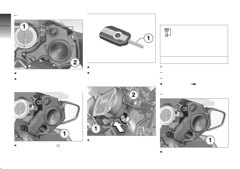
with audio system
4
64
Remove screws 1.
Carefully remove speaker
z
Operation
unit 2, noting the plug.
OE
Flip open the key bit.
Hold the radio-operated key by
the key bit 1.
cluster 1 (arrow), level with
the warning and indicator lights.
Time during which the
engine has to be started.
The unlocking procedure has
to be repeated if this time is
allowed to expire.
30 s
Pre-ride check is performed.
Key has been recognised.
Engine can be started.
Start engine ( 117).
with audio system
OE
Disconnect plug 1.
Hold the radio-operated key to
the rear of the instrument
Connect plug 1.
Page 67
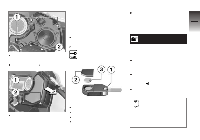
Seat speaker unit 2 in the
mount.
Install screws 1.
Hold speaker cover 1 in position and install screws 2.
Replace the battery of the
radio-operated key
If the radio-operated key does
not react when you short-press
or long-press a button:
The battery in the radio-operated key is not at full capacity.
Change the battery.
The battery symbol appears
on the display.
Press button 1.
Bitted key flips out.
Push up battery cover 2.
Remove battery 3.
Dispose of the old battery in
accordance with all applicable
laws and regulations; do not
attempt to dispose of batteries
as domestic waste.
ATTENTION
Unsuitable or incorrectly inserted batteries
Component damage
Use a battery compliant with
the manufacturer's specifications.
When inserting the battery,
always make sure polarity is
correct.
Insert the new battery with the
positive terminal up.
Battery type
For Keyless Ride radio-operated key
CR 2032
4
65
z
Operation
Page 68
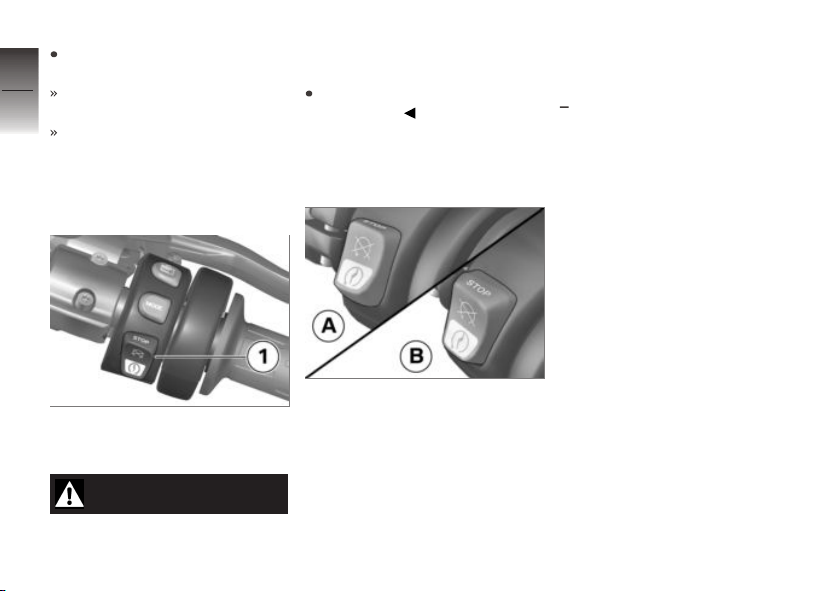
Install seal 1 and battery
cover 2.
4
Red LED on the instrument
66
panel flashes.
The radio-operated key is again
ready for use.
Emergency off switch (kill switch)
z
Operation
1 Emergency off switch (kill
switch)
WARNING
Operation of the kill switch
while riding
Risk of fall due to rear wheel
locking
Do not operate the kill switch
when riding.
The emergency off switch is a
kill switch for switching off the
engine quickly and easily.
A Engine switched off
B Normal operating position
(run)
Intelligent emergency call
with intelligent emergency
OE
call
Emergency call via BMW
Only press the SOS button in
an emergency or when help is
necessary.
Even if an emergency call using
BMW is not possible, the system
may make an emergency call to
a public emergency call number.
This depends on the respective
mobile phone network and the
national regulations.
The emergency call is not able to
be ensured because of technical
reasons due to unfavourable conditions, e.g. in areas where there
is no mobile phone reception.
Page 69
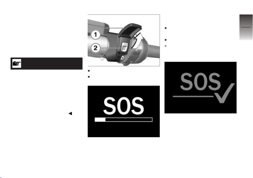
Language for emergency
call
Each vehicle has a language assigned to it depending on the
market for which it is intended.
The BMW Call Center answers in
this language.
NOTICE
A changeover of the language for
the emergency call can only be
performed by the BMW Motorrad
partner. The language assigned
to the vehicle varies from the selectable language the driver can
choose as the display language
in the multifunction display.
Manual emergency call
Requirement
An emergency call has occurred.
The vehicle is at a standstill. The
ignition is switched on.
Open cover 1.
Press the SOS button 2.
The remaining time until the
emergency call is transmitted
is displayed via the progress bar.
During this time, the emergency
call can be cancelled by pressing
and holding the SOS button.
Operate the emergency-off
switch to stop the engine.
Remove helmet.
After expiry of the timer, a
voice contact to the BMW Call
Center is established.
The connection was established.
4
67
z
Operation
Page 70
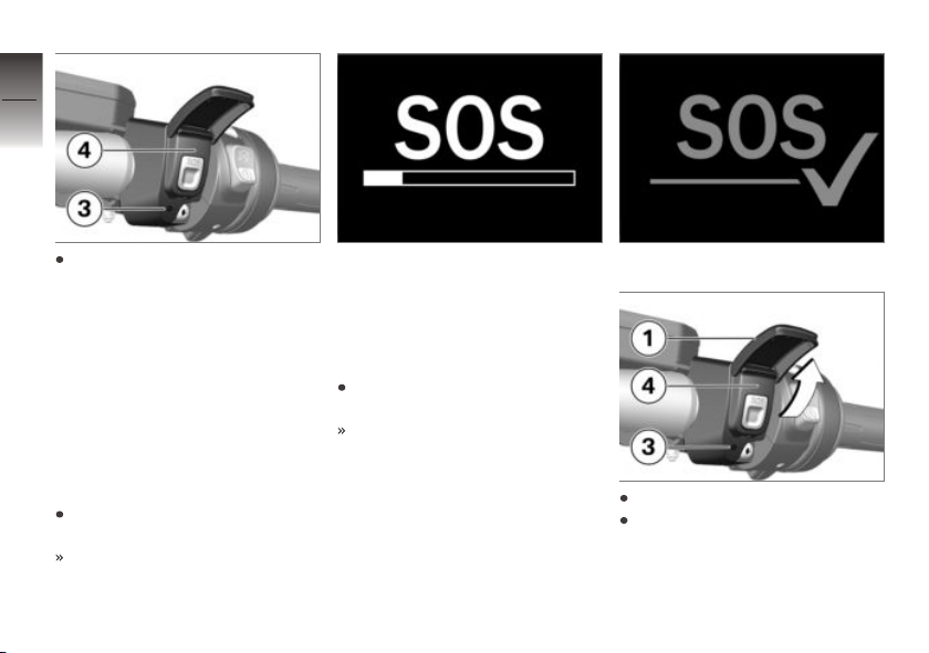
4
68
Provide information to the
emergency services using the
microphone 3 and speaker 4.
z
Operation
Automatic emergency call
The intelligent emergency call
is active after the ignition is
switched on and reacts if a fall or
crash occurs.
Emergency call in the
event of a light fall
A light fall or a crash was detected.
An acoustic signal is sounded.
The remaining time until the
emergency call is transmitted
is displayed via the progress bar.
During this time, the emergency
call can be cancelled by pressing
and holding the SOS button.
If possible, remove helmet and
stop engine.
After expiry of the timer, a
voice contact to the BMW Call
Center is established.
The connection was established.
Open cover 1.
Provide information to the
emergency services using the
microphone 3 and speaker 4.
Page 71
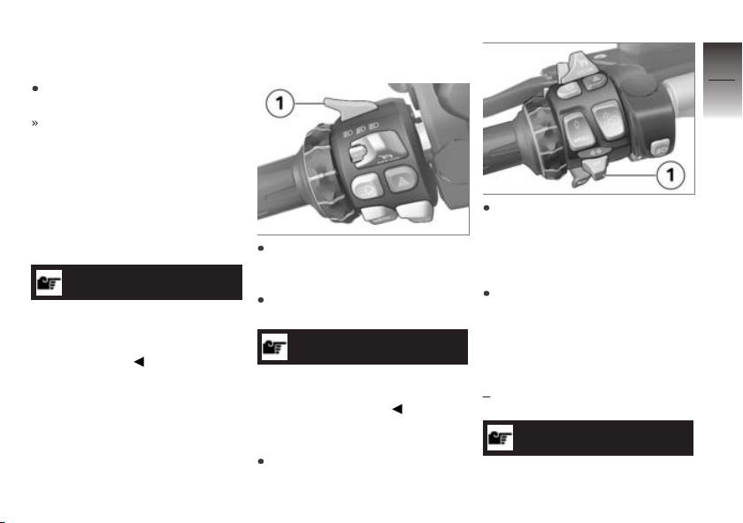
Emergency call in the
event of a severe fall
A severe fall or a crash is detected.
The emergency call is placed
automatically without delay.
Lights
Side light
The side lights switch on automatically when the ignition is
switched on.
NOTICE
The side lights place a strain on
the battery. Do not switch the
ignition on for longer than absolutely necessary.
Low-beam headlight
The low-beam headlight switches
on automatically when you start
the engine.
High-beam headlight and
headlight flasher
Push switch 1 forward to
switch on the high-beam
headlight.
Pull switch 1 back to operate
the headlight flasher.
NOTICE
The high-beam headlight can
also be switched on when the
engine is not running.
Parking lights
Switch off the ignition.
Immediately after switching off
the ignition, push button 1 to
the left and hold it in this position until the parking lights
come on.
Switch the ignition on and off
again to switch off the parking
lights.
Operate LED additional
headlights
with additional headlight
NOTICE
The auxiliary headlights have approval as fog lights and their use
OE
4
69
z
Operation
Page 72
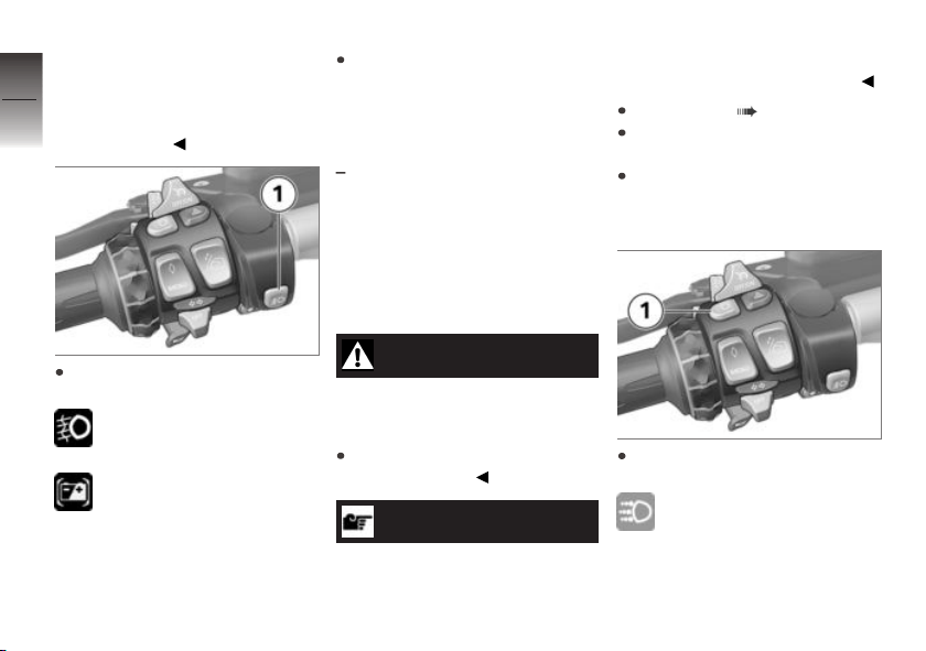
is permissible in bad weather
conditions only. Always comply
4
with the road traffic regulations in
70
force in the country in which the
vehicle is used.
z
Operation
Press button 1 again to switch
off the LED additional headlights.
Day run lights
with daytime riding light
Manual daytime riding
light
Requirement
Automatic daytime riding light is
switched off.
OE
more visible to oncoming traffic.
This improves daytime visibility.
Start engine ( 117).
Call up the Settings menu
and then select Vehicle.
Select the DRL menu item and
switch Automatic DRL to
Off.
Press button 1 to switch on
the LED additional headlights.
The telltale light shows.
If this warning symbol ap-
pears it tells you that the
on-board system voltage is low.
If applicable, the auxiliary headlights might have been temporarily switched off.
WARNING
Switching on the daytime
riding light in the dark.
Risk of accident
Do not use the daytime riding
light in the dark.
NOTICE
By comparison with the lowbeam headlight, the daytime
running light makes the vehicle
Press button 1 to switch on
the daytime riding light.
The indicator light for the
daytime running light illu-
minates.
Page 73
The low-beam headlight, the
front side lights and the auxiliary headlight are switched off.
In the dark or in tunnels: Press
button 1 again to switch off the
daytime riding light and switch
on the low-beam headlight and
front side light. The auxiliary
headlight is also switched on
again.
NOTICE
The daytime riding light is
switched off after approximately 2 seconds and the highbeam headlight, low-beam
headlight, front side lights and
the additional headlight, as
appropriate, are switched on if
the high beam is switched on
while the daytime riding light is
on.
If the high beam headlight is
switched off again, the daytime
running light is not automat-
ically reactivated, but must be
switched on again if required.
Automatic daytime riding
light
WARNING
The automatic daytime riding light does not replace the
personal assessment of the
light conditions
Risk of accident
Switch off the automatic daytime riding light in poor light
conditions.
NOTICE
The changeover between
daytime riding light and lowbeam headlight including front
side lights can be effected
automatically.
Call up the Settings menu
and then select Vehicle.
Select the DRL menu item and
switch Automatic DRL to On.
The symbol for the automatic daytime running light
shows in the display.
If the ambient brightness decreases below a certain value,
the low beam headlight is automatically switched on (e. B.
in a tunnel). When sufficient
ambient brightness is detected, the daytime riding light is
switched back on. When the
daytime riding light is active,
the daytime riding light symbol
is displayed in the multifunction
display.
Manual operation of the
light when the automatic
system is switched on
If you press the button for the
daytime riding light the daytime
riding light is switched off and
the low-beam headlight and
4
71
z
Operation
Page 74
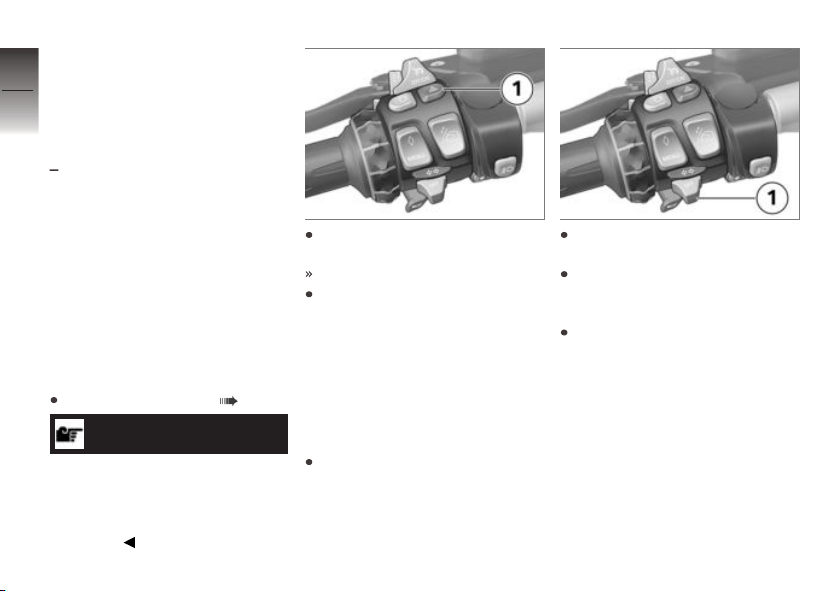
front side lights are switched
on (e. g. when you ride into
4
a tunnel, and the response of
72
the automatic daytime riding
light to the change in ambient
brightness is delayed).
If you press the button again
the daytime riding light is reactivated, in other words the
daytime riding light is switched
on again when ambient light is
bright enough.
z
Operation
Hazard warning lights system
Operating hazard warning
flashers
Switching on ignition ( 58).
NOTICE
The hazard warning flashers
place a strain on the battery.
Do not use the hazard warning
flashers for longer than absolutely
necessary.
Press button 1 to switch on
the hazard warning flashers.
Ignition can be switched off.
To switch off the hazard warning flashers, switch on the ignition if necessary and press
button 1 again.
Turn indicators
Operating the turn
indicators
Switch on the ignition.
Press button 1 to the left to
switch on the left turn indicator.
Press button 1 to the right to
switch on the right turn indicator.
Operate button 1 in the centre
position to switch off the turn
indicator.
Page 75
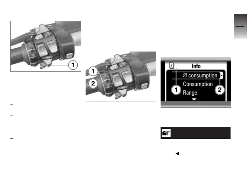
Comfort turn indicator
If button 1 has been pressed to
the right or left, the turn indicators are automatically switched
off under the following circumstances:
Speed below 30 km/h: after
50 m distance covered.
Speed between 30 km/h and
100 km/h: after a speed-dependent distance covered or in
case of acceleration.
Speed over 100 km/h: after
flashing five times.
If button 1 is pressed to the right
or left slightly longer, the turn in-
dicators only switch off automatically once the speed-dependent
distance covered is reached.
Multifunction display
Selecting menu
Press button 2 to step through
the sequence of menus, starting
with the Dynamic ESA menu.
Each time you press button 2
you call up the next menu in the
sequence; the number of menus
depends on the options fitted to
the motorcycle.
You also have the option of
pressing button 1 for direct
access to a favourite menu of
your choice.
With the exception of the Audio
section, you cannot access the
Settings menu unless the
vehicle is at a standstill.
The menu you selected appears
at position 1. The submenu you
selected 2 has a border.
NOTICE
See the separate Quick Reference Guide for an overview of all
menus.
4
73
z
Operation
Page 76
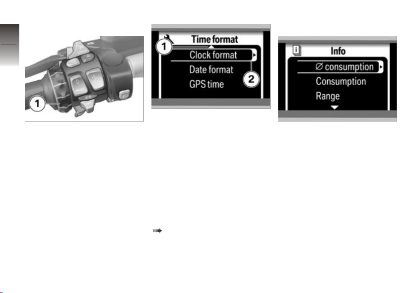
Selecting menu items
4
74
Use Multi-Controller 1 to move
the cursor in a menu.
z
Operation
An arrow 1 at the top or bottom
of the display indicates that there
are other items in this menu
that you can view by turning
the Multi-Controller in the corresponding direction. If arrow 2
appears in the cursor, you can
call up a submenu by pressing
the Multi-Controller to the right
(for information on the different
meaning in relation to average
values and list selections, see
( 74)).
Configuring settings
Direct selection
Move the cursor to a menu item
that does not require any further
settings to immediately activate
it.
Page 77

4
75
Resetting values
You can reset an average value
marked with an arrow 1 by longpressing the Multi-Controller to
the right.
Selecting from a list
A circle 1 beside each selectable item means that the items
are part of a selection list. The
current selection has been highlighted with a dot in the circle.
Select a list item with the cursor
and press the Multi-Controller
towards the right to activate or
deactivate it and modify the selection.
Setting numerical values
If there are one or more numerical values between the arrows 1,
you can increase the values by
turning the Multi-Controller up
or reduce the values by turning
it down. Press the Multi-Controller towards the right or left to
change between values.
z
Operation
Page 78
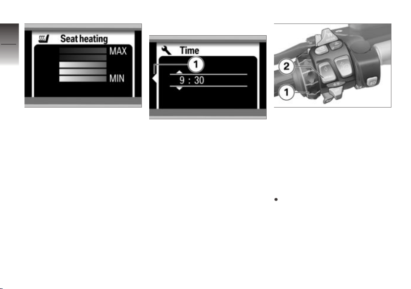
4
76
Exiting menu
Setting relative values
Adjust settings between two limit
values using a bar display. Turn
z
Operation
the Multi-Controller towards the
top to increase values and turn
it towards the bottom to reduce
the value you would like to adjust.
Arrow 1 appears when you are in
a submenu.
Press Multi-Controller 1 to the
left to return to the next highest
menu; press MENU button 2 to
return to the main menu.
If you want to hide the menus,
press Multi-Controller 1 to the
left in a main menu.
Selecting favourite menu
Select the main menu of your
choice.
Page 79
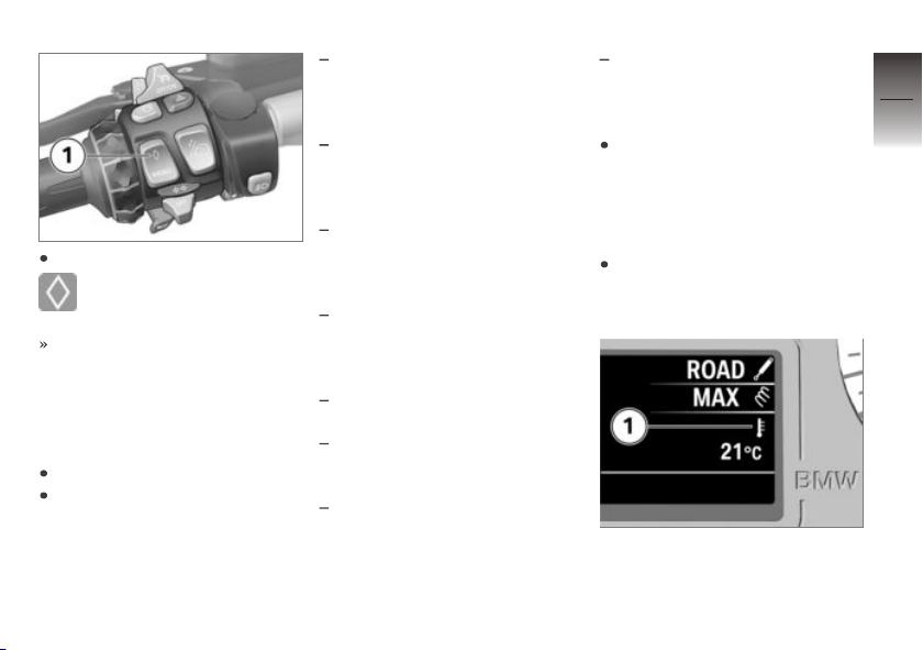
Press and hold down button 1.
The lozenge appears to the
right of the selected menu.
The menu you have selected
will subsequently be called up
whenever you press button 1.
Adapting mode of
presentation
Switch on the ignition.
Call up the Settings menu
and select the User menu
item.
The settings you can choose are
as follows:
Language: display language
(German, English, Spanish,
Italian, French, Dutch, Portuguese)
Time format - Clock
format: time in 12 hour
format (12 h) or 24 hour format
(24 h)
Time format - Date format:
date in Day.Month.Year format
(dd.mm.yy) or Month/Day/Year
format (mm/dd/yy)
Time format - GPS time:
transfers GPS time and GPS
date from the installed navigation system (On), (Off)
Brightness: display and
needle brightness
Start logo: displays the start
logo after switching on the ignition (On), (Off)
Default status: restore
factory default settings (if Re-
set! is displayed, press and
hold the Multi-Controller towards the right)
Background: displayed if the
radio is switched off: Empty:
off, Logo: logo (RT), Speed
ind.: digital speed.
Use the Multi-Controller to
configure the desired settings.
On-board computer
Select display
Call up the Information
menu and then select the desired information.
The following information can be
displayed in the area 1:
4
77
z
Operation
Page 80
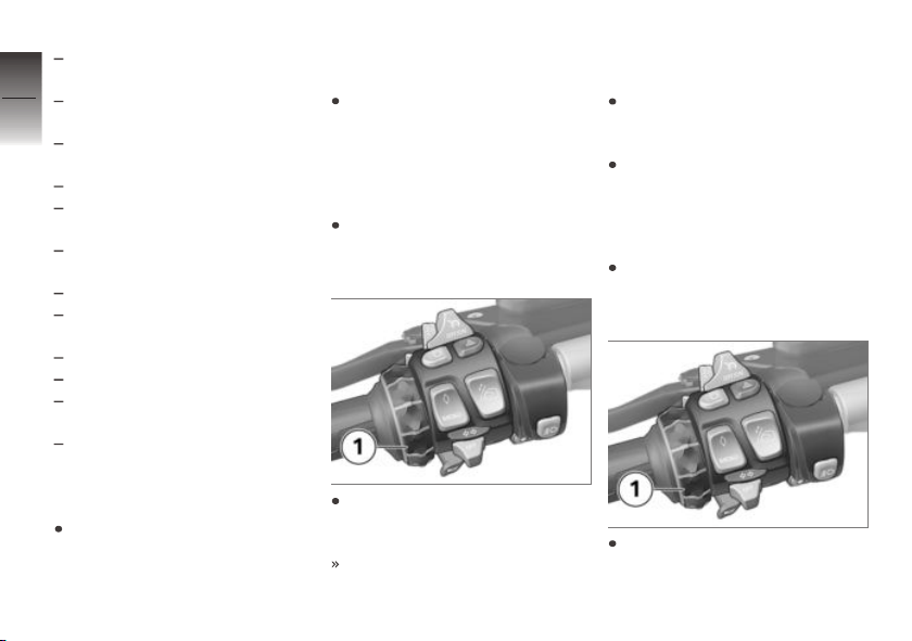
Ø consumption: Average
consumption
4
Consumption: Current con-
78
sumption
Range: Range with remaining
fuel
Ø speed: Average speed
Temperature: Ambient tem-
perature
Tyre pressure: Tyre inflation
pressures
Stopwatch: Stopwatch
z
Operation
Trav. times: Travelling
times
Date: Current date
Oil level: Engine oil level
Veh. voltage: Vehicle
voltage
Off: No display
Resetting the average
values
Call up the Information
menu and then select the av-
erage value you would like to
reset.
Push the Multi-Controller to
the right and hold it in this position until the average value is
reset.
Operate stopwatch
Call up the Information
menu and then select the
Stopwatch menu item.
With the stopwatch stopped,
push Multi-Controller 1 to the
right to start the stopwatch.
The stopwatch continues timing even if you select some
other reading or switch off the
ignition.
When the stopwatch is running,
push Multi-Controller 1 to the
right to stop the stopwatch.
Push Multi-Controller 1 to the
right and hold it in this position
to reset the stopwatch.
Measuring travel times
Call up the Information
menu and then select the
Trav. times menu item.
Push Multi-Controller 1 to the
right and hold it in this position
to reset the travel time.
Page 81
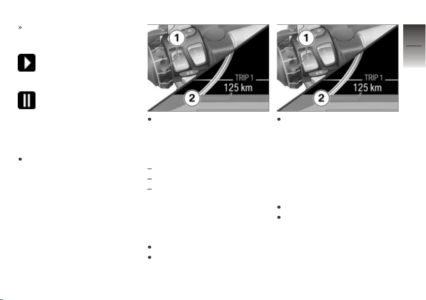
Timing continues even if you
select some other reading or
switch off the ignition.
Time during which the motorcycle was on the move
since the last reset.
Time during which the motorcycle was at a standstill
since the last reset.
Trip recorder
Select trip recorder
Switch on the ignition.
Go to Trip menu with MultiController 1, then select the
desired trip recorder 2.
The following counters can be
displayed:
Trip recorder 1 (Trip 1)
Trip recorder 2 (Trip 2)
The automatic trip recorder
(Trip Auto.) automatically
resets eight hours after the ig-
nition is switched off.
Reset trip recorder
Switch on the ignition.
Select desired trip recorder.
Keep Multi-Controller 1
pressed to the right until the
trip recorder 2 has been reset.
Automatic Stability Control (ASC)
Switching ASC function
off and on
Switch on the ignition.
Call up the Settings menu
and then select the ASC menu
item.
4
79
z
Operation
Page 82
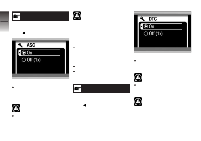
4
80
z
Operation
NOTICE
This menu cannot be called up
while the motorcycle is on the
move.
Select Off (1x) to switch
off ASC once and reactivate
it when the ignition is switched
on the next time.
lights up.
Select On to switch on the
ASC. Alternatively: switch the
ignition off and then on.
goes out, if self-diagnosis
has not completed the ASC
indicator and warning light starts
flashing.
Dynamic Traction Control (DTC)
with riding modes Pro
Switching the DTC
function off/on
Switch on the ignition.
Open the Settings menu
and then select the DTC menu
item.
NOTICE
This menu cannot be called up
while the motorcycle is on the
move.
OE
Select Off (1x) to switch off
DTC once until the next time
you switch on the ignition.
lights up.
Select On to switch on DTC.
Alternatively: switch the ignition
off and then on.
goes out, if self-diagnosis
has not completed the DTC
indicator and warning light starts
flashing.
Page 83
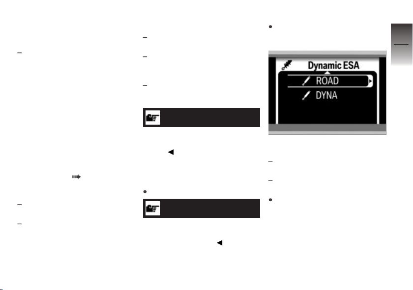
Electronic Suspension
Adjustment (DESA)
with Dynamic ESA
Dynamic ESA possible
settings
The electronic chassis and
suspension setting Dynamic ESA
is able to adjust your motorcycle
automatically to the load. If the
spring setting is set to AUTO, the
rider does not have to change
the load setting.
See the "Engineering details"
section for more information on
Dynamic ESA ( 137).
Available damping modes
For comfortable on-road riding:
ROAD
For dynamic on-road riding:
DYNA
OE
Available load settings
Predefined minimum spring
setting: MIN
Active riding position equaliser
with automatic spring setting:
AUTO
Predefined maximum spring
setting: MAX
NOTICE
BMW Motorrad recommends the
Auto chassis and suspension
setting.
Adjusting the chassis and
suspension
Start the engine.
NOTICE
You can adjust the damping
characteristic while the motorcycle is on the move.
Call up the Dynamic ESA
menu.
The possible damping settings
are displayed.
ROAD: Damping for comfortable
on-road riding.
DYNA: Damping for dynamic
on-road riding.
Select the damping characteristic you want or move the
cursor down to set the vehicle
load.
4
81
z
Operation
Page 84
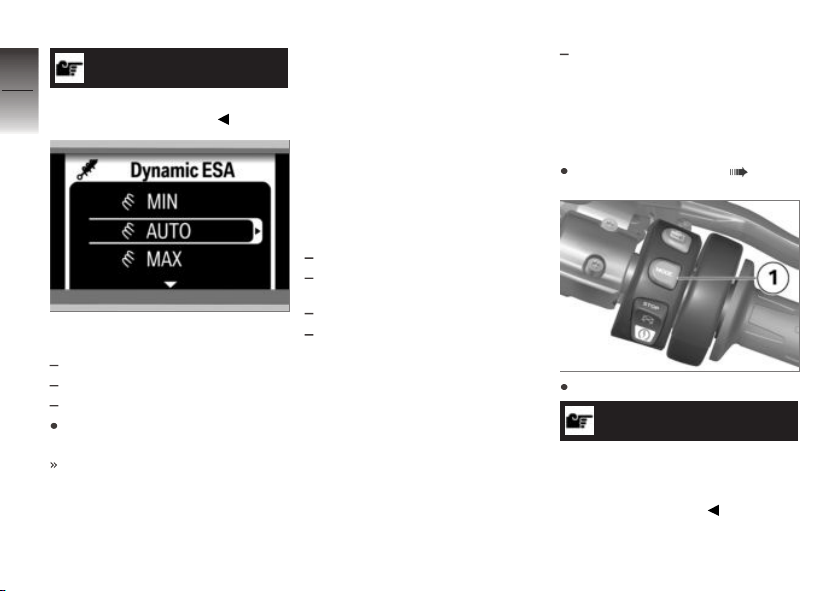
4
82
z
Operation
NOTICE
The load cannot be set while the
motorcycle is in motion.
The possible load settings are
displayed.
MIN: Minimum spring setting
AUTO: Automatic spring setting
MAX: Maximum spring setting
Select the desired loading variant.
The chassis and suspension is
adjusted as per the selection
and the Dynamic ESA display
is adapted to the new setting.
Symbols for load and damping
action are shown in grey during
the adjustment procedure.
Riding mode
Using the riding modes
BMW Motorrad has developed
3 operational scenarios for your
motorcycle from which you can
select the scenario suitable for
your situation:
Riding on a rain-wet roadway.
Riding on a dry roadway.
with riding modes Pro
Dynamic riding on a dry road
surface.
The optimum interplay of engine
characteristic and ASC/DTC control is provided for each of these
three scenarios.
OE
with Dynamic ESA
The chassis and suspension setting also adjusts to the chosen
scenarios.
OE
Setting riding mode
Switching on ignition ( 58).
Press button 1.
NOTICE
See the section entitled "Engineering details" for more information on the various ride modes
that can be selected.
Page 85
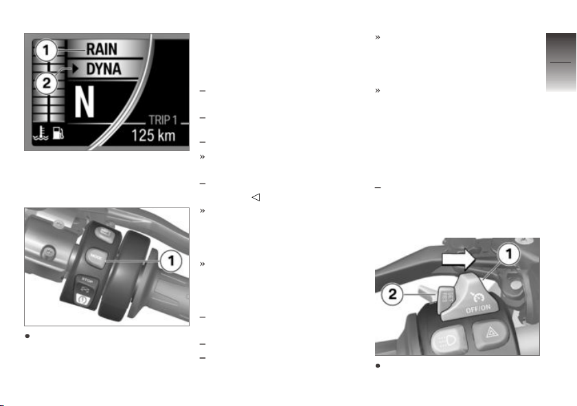
The selection arrow 2 and the
active riding mode 1 are displayed.
Press button 1 repeatedly until the required riding mode is
indicated next to the selection
arrow.
The following ride modes can be
selected:
RAIN: For riding on a rain-wet
road.
ROAD: For riding on a dry road.
with riding modes Pro
The following riding mode can
also be selected:
DYNA: For dynamic riding on a
dry road.
With the motorcycle at a stand-
still, the selected mode is ac-
tivated after approximately two
seconds.
The newly selected riding
mode is activated as you
ride only when the following
preconditions are satisfied:
Throttle grip is in the idle posi-
tion.
Brake is not applied.
Cruise control is not active.
OE
After activating the new riding
mode, the symbols for coolant
temperature and fuel level are
displayed again.
The adjusted riding mode with
the associated adaptations of
ASC/DTC and Dynamic ESA
remain available even after having switched off the ignition.
Cruise-control system
with cruise control
Switching on cruise
control
Slide switch 1 to the right.
OE
4
83
z
Operation
Page 86
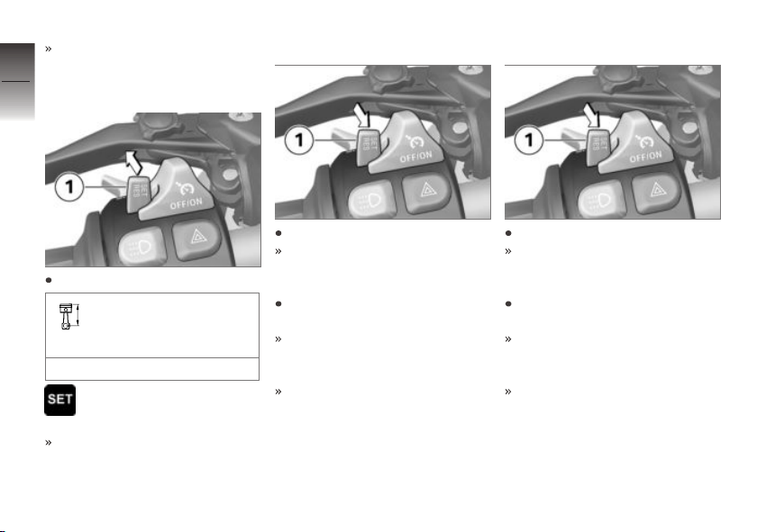
Button 2 is enabled for operation.
4
84
Saving road speed
Accelerating
Decelerating
z
Operation
Briefly push button 1 forward.
Adjustment range for
cruise control (gear-de-
pendent)
10...210 km/h
Telltale light for cruise con-
trol shows.
The motorcycle maintains your
current cruising speed and the
setting is saved.
Briefly push button 1 forward.
Speed is increased by approx.
1 km/h each time you push the
button.
Push button 1 forward and
hold it in this position.
The motorcycle accelerates
with infinite variability (no
steps).
The current speed is maintained and saved if button 1 is
not pushed again.
Briefly push button 1 back.
Speed is reduced by approx.
1 km/h each time you push the
button.
Push button 1 back and hold it
in this position.
The motorcycle decelerates
with infinite variability (no
steps).
The current speed is maintained and saved if button 1 is
not pushed again.
Page 87
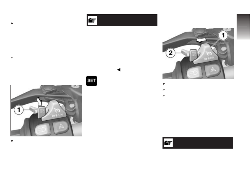
Deactivate cruise control
Brake, pull the clutch lever
or turn the throttle twistgrip
(close the throttle by turning
the twistgrip back past the
idle position) to deactivate the
cruise-control system.
Telltale light for cruise control
goes out.
Resuming former cruising
speed
NOTICE
Opening the throttle does not
deactivate the cruise-control system. If you release the twistgrip
the motorcycle will decelerate
only to the cruising speed saved
in memory, even though you
might have intended slowing to
a lower speed.
Telltale light for cruise control shows.
Switching off cruise
control
Slide switch 1 to the left.
The system is deactivated.
Button 2 is disabled.
Hill Start Control
Operate Hill Start Control
Requirement
The vehicle is at a standstill.
4
85
z
Operation
Briefly push button 1 back to
return to the speed saved beforehand.
ATTENTION
Failure of the drive-off assistant
Page 88
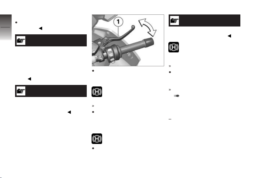
Risk of accident
Secure the vehicle by braking
4
manually.
86
NOTICE
Hill Start Control is purely a comfort system to facilitate holding
the machine and pulling way
on uphill gradients and should
not be confused with a parking
brake.
z
Operation
NOTICE
See the section entitled "Engineering details" for more information on Hill Start Control.
Operate the brake lever 1 or
footbrake lever strongly and
release again quickly.
Green holding symbol is
displayed.
Hill Start Control is activated.
To switch off the
Hill Start Control, operate the
brake lever 1 or footbrake lever
again.
The holding symbol disappears.
Alternatively, ride off in 1st or
2nd gear.
NOTICE
When riding off, Hill Start Control
is automatically deactivated.
Once the brake has been
fully released, the holding
symbol disappears.
Hill Start Control is deactivated.
See the "Engineering details"
section for more information on
Hill Start Control.
Hill Start Control function
( 143)
Operating
Hill Start Control Pro
with riding modes Pro
Requirement
Automatic Hill Start Control Pro
switched on.
OE
Page 89
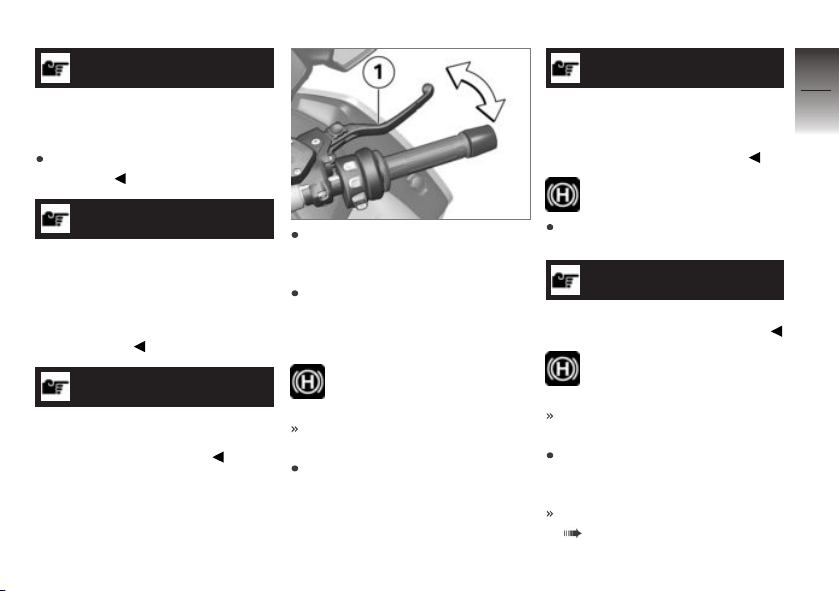
ATTENTION
Failure of the drive-off assistant
Risk of accident
Secure the vehicle by braking
manually.
NOTICE
The drive-off assistant Hill Start
Control Pro is only a comfort system to enable easier riding off on
gradients and should not be confused with an electromechanical
holding brake.
NOTICE
The Hill Start Control Pro driveoff assistant should not be used
on inclines of over 40 %.
Operate the brake lever 1 or
footbrake lever strongly and
release again quickly.
Alternatively, apply the brake
for about one second beyond
the vehicle reaching a standstill
on an incline of at least 5 %.
Green holding symbol is
displayed.
Hill Start Control Pro is activated.
To switch off the
Hill Start Control Pro, operate
the brake lever 1 or footbrake
lever again.
NOTICE
If Hill Start Control Pro has been
deactivated using the brake lever,
automatic Hill Start Control is
deactivated for the next 4 m.
White holding symbol is
displayed.
Alternatively, ride off in 1st or
2nd gear.
NOTICE
When riding off, Hill Start Control
Pro is automatically deactivated.
White holding symbol is
displayed.
Hill Start Control Pro is deactivated.
See the "Engineering details"
section for more information on
Hill Start Control Pro:
Hill Start Control function
( 143)
4
87
z
Operation
Page 90
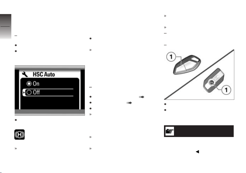
Switching automatic Hill
4
Start Control Pro on and
off
88
with riding modes Pro
Switch on the ignition.
Go to menu Settings, then
select menu item HSC AUTO.
z
Operation
To switch on automatic Hill
Start Control Pro, select On.
White holding symbol is
displayed.
If the brake is actuated for
approximately one second
after the vehicle has come to
OE
a standstill and the motorcycle
is on a gradient of at least 5%,
Hill Start Control Pro is automatically activated.
To switch off automatic Hill
Start Control Pro, select Off.
The selected setting remains
stored even after the ignition is
switched off.
Anti-theft alarm (DWA)
Activation
with anti-theft alarm (DWA)
Switching on ignition ( 58).
DWA Adapting ( 90).
Switch off the ignition.
If the alarm system is activated,
then the alarm system will be
automatically activated when
the ignition is switched off.
Activation takes approximately
30 seconds to complete.
Turn indicators flash twice.
OE
Confirmation tone sounds
twice (if programmed).
Anti-theft alarm is active.
with central locking system
or
with Keyless Ride
Switch off the ignition.
Press button 1 of the remote
control or radio-operated key
twice.
NOTICE
See also the other functions of
the remote control for the central
locking system.
OE
OE
Page 91
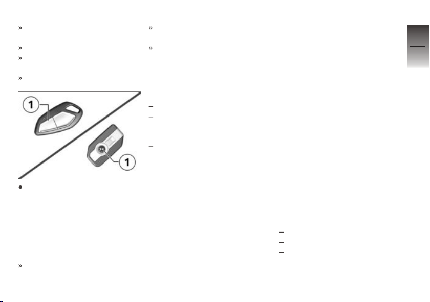
Activation takes 30 seconds to
complete.
Turn indicators flash twice.
Confirmation tone sounds
twice (if programmed).
Anti-theft alarm is active.
To deactivate the motion
sensor (e.g. to transport the
motorcycle by train when
the severe movements may
activate the alarm), press
button 1 of the remote control
or radio-operated key again
during the activation phase.
Turn indicators flash three
times.
Confirmation tone sounds three
times (if programmed).
Motion sensor has been deactivated.
Alarm signal
A DWA alarm can be triggered
by:
motion sensor
an attempt to use an unauthorised vehicle key to switch on
the ignition
disconnection of the DWA antitheft alarm from the motorcycle's battery (DWA internal
battery in the anti-theft alarm
provides power - alarm tone
only, the turn indicators do not
flash).
All functions are sustained even
if the internal battery of the DWA
anti-theft alarm system is flat; the
only difference is that an alarm
cannot be triggered if the system
is disconnected from the motorcycle's battery.
An alarm lasts for approximately
26 seconds. While an alarm is in
progress an alarm tone sounds
and the turn indicators flash. The
type of alarm tone can be set by
an authorised BMW Motorrad
dealer.
If an alarm was triggered while
the motorcycle was unattended,
the rider is notified accordingly
by an alarm tone sounding once
when the ignition is switched on.
The DWA LED then indicates
the reason for the alarm for one
minute.
Light signals issued by the
DWA LED:
Flashes 1x: Motion sensor 1
Flashes 2x: Motion sensor 2
Flashes 3x: Ignition switched
on with unauthorised vehicle
key
4
89
z
Operation
Page 92
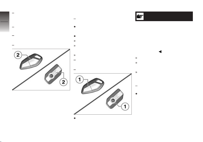
Flashes 4x: Disconnection of
the DWA anti-theft alarm from
4
the motorcycle's battery
90
Flashes 5x: Motion sensor 3
with central locking system
or
with Keyless Ride
z
Operation
An activated alarm can be cancelled at any time by pressing
button 2 of the remote control or
radio-operated key without deactivating the DWA.
OE
OE
Deactivation
with anti-theft alarm (DWA)
Kill switch in operating position
(run).
Switch on the ignition.
Turn indicators flash once.
Confirmation tone sounds once
(if programmed).
DWA has been switched off.
with central locking system
or
with Keyless Ride
Press button 1 of the radiooperated key once.
OE
OE
OE
NOTICE
The alarm function is reactivated
after 30 seconds if "activation
after ignition off" has been selected if the alarm function is deactivated using the radio-operated
key and the ignition is not then
switched on.
Turn indicators flash once.
Confirmation tone sounds once
(if programmed).
DWA has been switched off.
DWA Adapting
with anti-theft alarm (DWA)
Call up the Settings menu
and select the Vehicle Alarm system menu item.
OE
Page 93
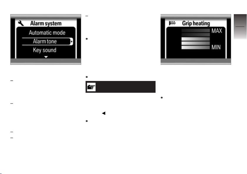
The following settings are available:
Automatic mode - On: alarm
system is automatically activated after having switched off
the ignition.
Automatic mode - Off:
alarm system must be
activated with the remote
control after having switched
off the ignition.
Alarm tone: alarm tone type.
Key sound - On: the turn in-
dicators and a sound confirm
having switched the alarm system on or off.
Key sound - Off: exclusively
the turn indicators confirm having switched the alarm system
on or off.
Configure the desired settings
using the Multi-Controller.
Heating
Operating the heated
handlebar grips
Start the engine.
NOTICE
The heating in the heated
handlebar grips can be activated
only when the engine is
running.
Call up the Grip heating
menu.
The grips can be heated in five
levels. The fifth level is intended
to quickly heat up the grips; you
should then shift down to one of
the lower levels.
Select the heating stage you
want.
4
91
z
Operation
Page 94
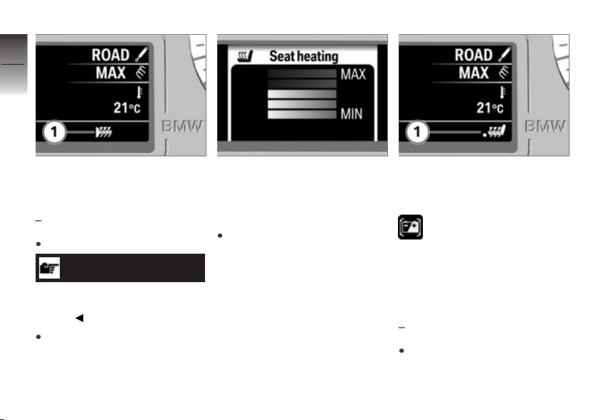
4
92
The symbol 1 shows that the
grip heating is switched on.
z
Operation
Front-seat heating
with seat heating
Start the engine.
NOTICE
Seat heating can be activated
only when the engine is
running.
Call up the Seat heating
menu.
OE
The rider's seat can be heated
in five levels. The fifth level is
intended to quickly heat up the
seat; you should then shift down
to one of the lower levels.
Select the heating stage you
want.
The symbol 1 shows that the
rider's seat heating is switched
on.
If this warning symbol ap-
pears it tells you that the
on-board system voltage is low.
If applicable, the seat heating
might have been temporarily
switched off.
Rear-seat heating
with seat heating
Start the engine.
OE
Page 95
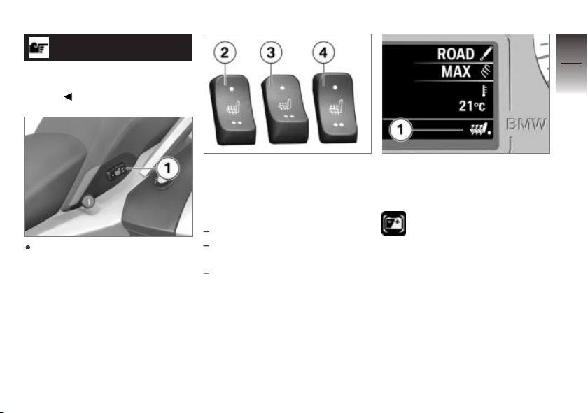
NOTICE
Seat heating can be activated
only when the engine is
running.
4
93
Set switch 1 to the desired
heating stage.
The rear seat has two-stage
heating. Stage two is for heating
the seat quickly: it is advisable to
switch back to stage one as soon
as the seat is warm.
2 Switch centred: Heating off.
3 One-dot section of switch
pressed: 50 % heating power.
4 Two-dot section of switch
pressed: 100 % heating
power.
The symbol 1 shows that
the passenger seat heating is
switched on.
If this warning symbol ap-
pears it tells you that the
on-board system voltage is low.
If applicable, the seat heating
might have been temporarily
switched off.
z
Operation
Page 96
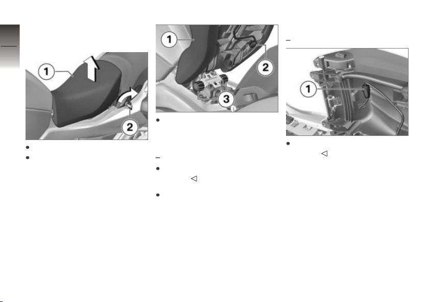
Front seat
4
Removing front seat
94
z
Operation
Turn ignition key 2 clockwise.
Slightly raise front seat 1 at the
back.
Work front seat 1 to the rear to
disengage it from seat retainer
bridge 3 and remove.
with seat heating
Disconnect plug 2 for the seat
heating.
Remove the front seat and
place it, upholstered side down,
on a clean, dry surface.
OE
Installing front seat
with seat heating
Connect plug 1 of the seat
heating.
OE
Page 97
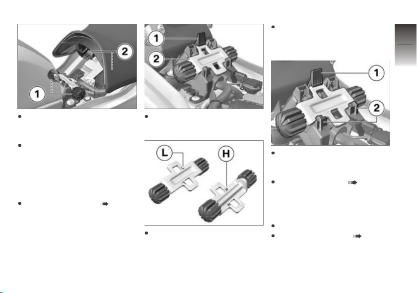
Turn the adjusting plate to
position H for the higher seat
height.
4
95
Position the front seat with
mounts 2 in rubber buffers 1
on left and right.
Lower the rear of the front seat
and engage the seat in the
latching mechanism.
Adjusting front-seat
height
Removing front seat ( 94).
Push latch 1 forward and remove adjusting plate 2.
Turn the adjusting plate to
position L for the lower seat
height.
Insert the adjusting plate in the
desired position into mounts 2
and then push it into latch 1.
Installing front seat ( 94).
Rear seat
Removing rear seat
Switch off the ignition.
Removing front seat ( 94).
z
Operation
Page 98
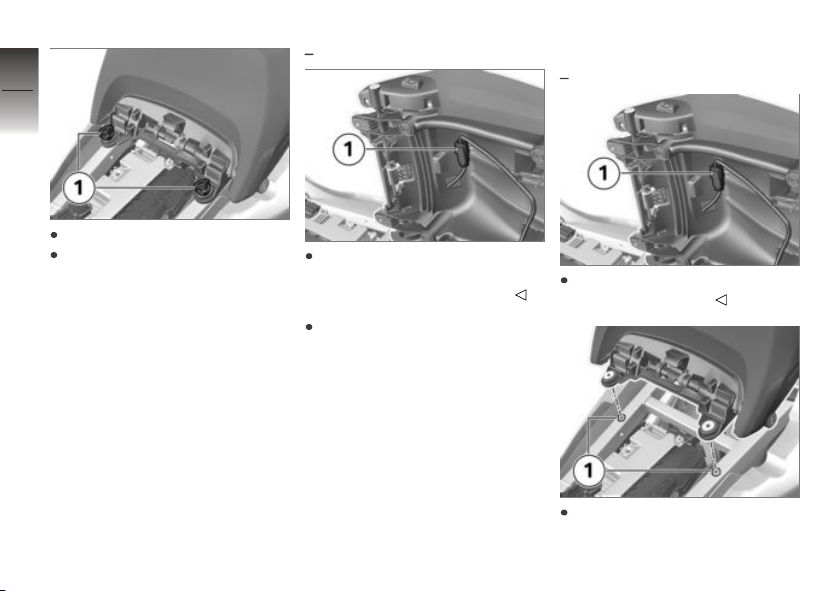
4
96
Remove the screws 1.
Slightly pull the passenger seat
towards the front and lift it.
z
Operation
with seat heating
Disconnect the plug connection 1 of the seat heating and
remove the passenger seat.
Place the seat, upholstered
side down, on a clean surface.
OE
Install the rear seat
with seat heating
Connect the plug connection 1
for the seat heating.
Place passenger seat on the
mountings 1.
OE
Page 99
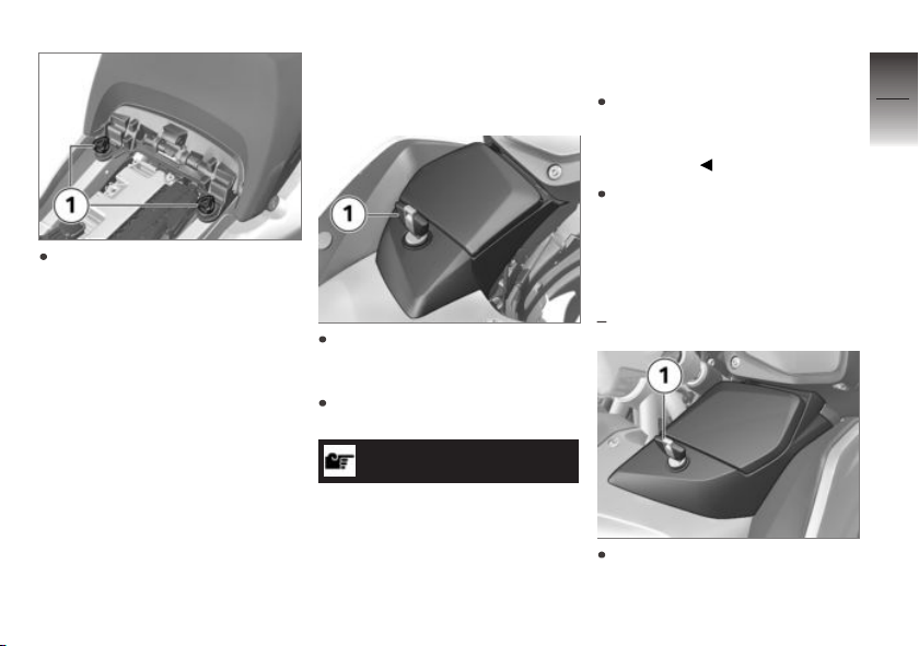
Fit bolts 1.
Stowage compartment
Operating the left storage
compartment
Unlock and lock the lock 1 of
the storage compartment using
the ignition key.
To open the lid, press the unlocked lock barrel down.
ATTENTION
High temperatures in the
storage compartments, particularly in summer
Damage to objects stowed away,
particularly electronic devices,
such as mobile phones and MP3
players
Consult the operating instructions of your electronic device
and check for possible usage
restrictions.
In summer, do not place heatsensitive objects in the storage
compartments.
Operating the right
storage compartment
with audio system
Unlock and lock the lock 1 of
the storage compartment using
the ignition key.
OE
4
97
z
Operation
Page 100
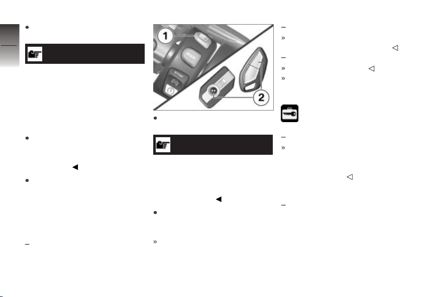
To open the lid, press the unlocked lock barrel down.
4
98
z
Operation
ATTENTION
High temperatures in the
storage compartments, particularly in summer
Damage to objects stowed away,
particularly electronic devices,
such as mobile phones and MP3
players
Consult the operating instructions of your electronic device
and check for possible usage
restrictions.
In summer, do not place heatsensitive objects in the storage
compartments.
Central locking system
Lock
with central locking system
Switch on the ignition and
press button 1.
NOTICE
Only vehicles without Keyless
Ride are shipped accompanied
by a separate remote control for
the central locking system and
the alarm system.
Alternatively: Press button 2
on the remote control or the
radio-operated key.
OE
The stowage compartment
in the left side panel and the
cases are locked.
with audio system
The stowage compartment in
the right side panel is locked.
with topcase
The topcase is locked.
These locks cannot
subsequently be unlocked
manually.
The locked symbol appears
on the display.
with anti-theft alarm (DWA)
The functions of the remote
control for the anti-theft alarm
are described in the corresponding section.
OE
OA
Unlocking
with central locking system
OE
OE
 Loading...