


Hood
User Manual
Dunstabzugshaube
Bedienungsanleitung
Hotte
Manuel d'utilisation
Okap
Instrukcja obsługi
Napa
Navodila za uporabo
CWB 9831 ANP
Please read this user manual first!
Dear Customer,
Thank you for prefering a Beko product. We hope that you get the best results from your product which has been manufactured with high quality and state-of-the-art technology. Therefore, please read this entire user manual and all other accompanying documents carefully before using the product and keep it as a reference for future use. If you handover the product to someone else, give the user manual as well. Follow all warnings and information in the user manual.
Remember that this user manual is also applicable for several other models. Differences between models will be identified in the manual.
Explanation of symbols
Throughout this user manual the following symbols are used:
C Important information or useful hints about usage.
A Warning for hazardous situations with regard to life and property.
B Warning for electric shock.
Packaging materials of the product are manufactured from recyclable materials in accordance with our National Environment Regulations.
Do not dispose of the packaging materials together with the domestic or other wastes. Take them to the packaging material collection points designated by the local authorities.
This product was manufactured using the latest technology in environmentally friendly conditions.
TABLE OF CONTENTS
1 Recommendations and Suggestions 4
1.1 Installation. . . . . . . . . . . . . . . . . . . . . . . . . . 4
1.2 Use. . . . . . . . . . . . . . . . . . . . . . . . . . . . . . . 5
1.3 Maintenance . . . . . . . . . . . . . . . . . . . . . . . . 5
2 Characteristics |
6 |
2.1 Components . . . . . . . . . . . . . . . . . . . . . . . . 6
2.2 Dimensions . . . . . . . . . . . . . . . . . . . . . . . . . 6
3 Installation |
7 |
3.1 Boring the wall . . . . . . . . . . . . . . . . . . . . . . 7 3.2 Mounting the hood body . . . . . . . . . . . . . . . 7 3.3 Connection . . . . . . . . . . . . . . . . . . . . . . . . . 8 3.3.1 Air Outlet In A Ducting Hood Version . . . . . 8 3.3.2 Air Outlet In A Recycling Hood Version . . . . 9 3.4 Electrical Connection . . . . . . . . . . . . . . . . . . 9
4 Use |
10 |
4.1 Control panel. . . . . . . . . . . . . . . . . . . . . . . 10
5 Maintenance |
11 |
5.1 Grease Filters . . . . . . . . . . . . . . . . . . . . . . 11
5.1.1Cleaning Metal SelfSupporting Grease Filters. . . . . . . . . . . . . . . . . . . . . . . . . . . 11
5.2 Activated charcoal filter (Recirculation
version) . . . . . . . . . . . . . . . . . . . . . . . . . 11 5.2.1 Replacing The Activated Charcoal Filter . . 11 5.3 Lighting unit . . . . . . . . . . . . . . . . . . . . . . . 11
Hood / User Manual |
3 / 51 EN |
|
|
1 Recommendations and Suggestions
The Instructions for Use apply to A several versions of this appliance.
Accordingly, you may find descriptions of individual features that do not apply to your specific appliance.
1.1 Installation
•The manufacturer will not be held liable for any damages resulting from incorrect or improper installation.
•The minimum safety distance between the cooker top and the extractor hood is 650 mm (some models can be installed at a lower height, please refer to the paragraphs on working dimensions and installation).
•Check that the mains voltage corresponds to that indicated on the rating plate fixed to the inside of the hood.
•For Class I appliances, check that the domestic power supply guarantees adequate earthing.
Connect the extractor to the exhaust flue through a pipe of minimum diameter 120 mm. The route of the flue must be as short as possible.
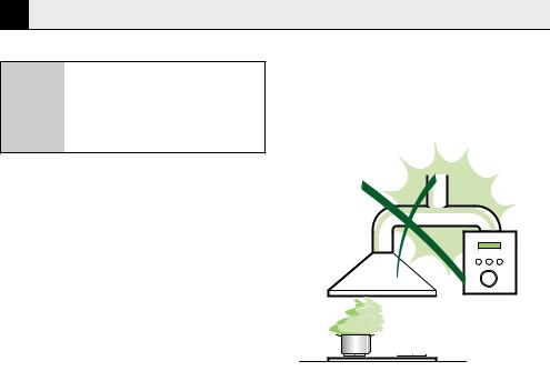
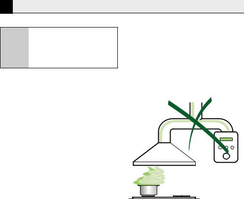
•Do not connect the extractor hood to exhaust ducts carrying combustion fumes (boilers, fireplaces, etc.).
•If the extractor is used in conjunction with nonelectrical appliances (e.g. gas burning appliances), a sufficient degree of aeration must be guaranteed in the room in order to prevent the backflow of exhaust gas. The kitchen must have an opening communicating directly with the open air in order to guarantee the entry of clean air. When the cooker hood is used in conjunction with appliances supplied with energy other than electric, the negative pressure in the room must not exceed 0,04 mbar to prevent fumes being drawn back into the room by the cooker hood.
•In the event of damage to the power cable, it must be replaced by the manufacturer or by the technical service department, in order to prevent any risks.
•If the instructions for installation for the gas hob specify a greater distance specified above, this has to be taken into account. Regulations concerning the discharge of air have to be fulfilled.
4 / 51 EN |
Hood / User Manual |
|
|
1 Recommendations and Suggestions
1.2 Use
The extractor hood has been designed exclusively for domestic use to eliminate kitchen smells.
•Never use the hood for purposes other than for which it has been designed.
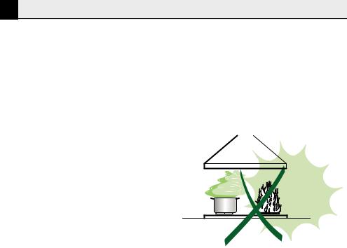
•Never leave high naked flames under the hood when it is in operation.
•Adjust the flame intensity to direct it onto the bottom of the pan only, making sure that it does not engulf the sides.
•Deep fat fryers must be continuously monitored during use: overheated oil can burst into flames.
•Do not flambè under the range hood; risk of fire
•This appliance is not intended for use by persons (including children) with reduced physical, sensory or mental capabilities, or lack of experience and knowledge, unless they have been given supervision or instruction concerning use of the appliance by a person responsible for their safety.
•Children should be supervised to ensure that they do not play with the appliance.
•“CAUTION: Accessible parts may become hot when used with cooking appliances.”.
1.3 Maintenance
•Switch off or unplug the appliance from the mains supply before carrying out any maintenance work.
•Clean and/or replace the Filters after the specified time period (Fire hazard).
•Clean the hood using a damp cloth and a neutral liquid detergent.
Hood / User Manual |
5 / 51 EN |
|
|
2 Characteristics
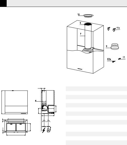
2.1 Components
Ref. |
Q.ty |
Product components |
11 Hood Body complete with: Controls, Light, Suction Unit, Filters, Lower Duct
71 PVC Pipe (fitted)
81 Inclinable grid (fitted)
91 Reduction flange ø 150-120 mm
101 Metal cover
Ref. |
Q.ty |
Assembly components |
11 |
1 |
Wall Plugs |
11a |
2 |
SB 12/10 Plugs |
12a |
1 |
Screws 4,2 x 44,4 |
|
Q.ty |
Documents |
|
1 |
Instruction Manual |
2.2 Dimensions
916
|
640 |
50 |
|
44.9 |
305 |
|
745.5 |
99 |
|
|
150-120 |
|
|
225 |
250 |
|
208 |
||
|
||
490 |
|
2.3 Technical Specifications
Width |
898 mm |
|
Depth |
490 mm |
|
Height |
916 mm |
|
Supply voltage |
220 - 240 V, 50-60 Hz |
|
Control |
3 positions |
|
Suction power |
765 m3/h |
|
Motor power |
275 W |
|
Lamp power |
1X9 W |
|
Fuse |
10 A |
|
Air outlet pipe |
150 mm |
|
diameter |
||
|
||
Net weight |
23.8 kg |
|
|
|
|
Gross weight |
33.2 kg |
|
|
|
|
Color |
Antracite |
|
|
|
Markings on the product or the values stated in other documents supplied with the product are values obtained under laboratory conditions as per relevant standards. These values may vary according to the usage of the product and ambient conditions.
6 / 51 EN |
Hood / User Manual |
|
|
3 Installation
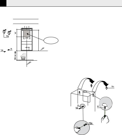
3.1 Boring the wall
Type Hood |
45 |
60 |
90 |
X |
180 |
240 |
390 |
|
|
|
847 |
586 |
|
|
|
|
|
53 |
|
Rear air outlet zone
If you want to use the hood in suction version with the air outlet at the back of the hood, make sure to follow the indications given below in the drawing for a correct boring operation of the air outlet opening.
When installing the hood in recycling version it has to be taken into consideration that space remaining between the hood and the upper limit (ceiling or self) is at least 8-10 cm.
On the wall, trace:
•a vertical line up to the ceiling or top limit, at the centre of the area where you intend to fit the hood;
•a horizontal line at: 650 mm min. above the cooking hob;
•As shown, mark a reference point at 847 mm above the horizontal reference line, and at X mm (X= see table in figure) to the right of the vertical reference line.
•Repeat this operation on the opposite side, checking levelling.
•Drill the points marked using a ø 12 mm bit
•Insert plugs with screws and brackets 11a in the holes then tighten them.
•As shown, mark a reference point at 53 mm above the horizontal reference line, at the center of the of the vertical reference line.
•Drill the points marked using a ø 8 mm bit.
•Insert the plug 11 in the hole.
3.2 Mounting the hood body
•Remove the metal grease filters by turning the handles provided.
•Adjust the two screws Vr, on brackets 11a, to a minimum.
•Hook the hood canopy onto the two brackets 11a.
•From inside the hood canopy, adjust the screws Vr to set the Hood Canopy level.
•Tighten the safety screw 12a.
Hood / User Manual |
7 / 51 EN |
|
|
3Installation
3.3Connection
3.3.1 Air Outlet In A Ducting Hood
Version
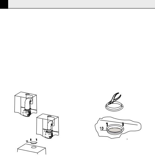
When installing the hood in ducting version, basing on the installer’s choice, a rigid or a flexible pipe with a ø 150 or 120 mm is used in order to connect the hood to the air outlet piping. The pipe connection can be made on the upper part or on the rear side of the hood.
Before connecting the hood to the air outlet ducting remove the lateral air outlet grid 8 and the plastic tube 7. The adapting flange 9 has to be removed only in case the connecting diameter is 150.
3.3.1.1 Rear Air Outlet
•When drilling the air outlet hole in the wall proceed in accordance with the scheme in the part concerning the wall drilling.
•Use a pair of tongs when breaking the rear air outlet hole in the wall.
•In case the connection is made by using a ø 120 mm pipe insert the reduction flange 9 on the hood body outlet.
•Fix the pipe with an adequate quantity of pipe clamps. This material is not supplied together with the hood.
•Remove the charcoal filter if present.
•Fix the metal cover 10 to the upper air outlet hole of the hood by using the screws supplied.
3.3.1.2 Upper Air Outlet
•In case the connection is made by using a ø 120 mm pipe insert the reduction flange 9 on the hood body outlet.
•Use a pair of tongs when removing the central part of the metal cover 10. Fix the cover to the air outlet hole of the hood by using the screws supplied.
•Fix the pipe with an adequate quantity of pipe clamps. This material is not supplied together with the hood.
•Remove the charcoal filter if present.
8 / 51 EN |
Hood / User Manual |
|
|

3 Installation
3.3.2 Air Outlet In A Recycling Hood
Version
•In case the components requested for the recycling functioning have been removed earlier these have to be positioned again.
•Put the plastic tube onto the flange 7.
•Place the air outlet grid 8 on the air outlet. Make sure that the position of the grid is correct.
•Make sure that charcoal filters have been placed inside the hood.
3.4 Electrical Connection
•Connect the hood to the mains through a twopole switch having a contact gap of at least 3 mm.
•Remove the grease filters (see paragraph Maintenance) being sure that the connector of the feeding cable is correctly inserted in the socket placed on the side of the fan.
Hood / User Manual |
9 / 51 EN |
|
|
4 Use
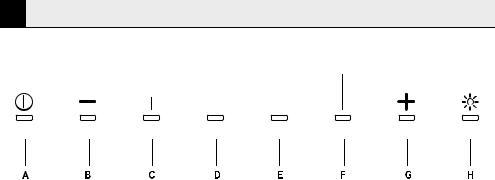
4.1 Control panel
Button |
Function |
Led |
|
|
|
A |
Turns the motor On/Off |
Leds off |
|
|
|
B |
Decreases the speed |
Leds C-D-E-F light up according to the speed that is set |
|
(Intensive-3-2-1) |
|
|
|
|
C |
|
Lights up when speed 1 is active |
|
|
|
D |
|
Lights up when speed 2 is active |
|
|
|
E |
|
Lights up when speed 3 is active |
|
|
|
F |
|
Lights up when Intensive speed is active |
|
|
|
G |
Increases the speed. |
Leds C-D-E-F light up according to the speed that is set |
|
(1-2-3-Intensive) |
|
|
|
|
H |
Turns the lights ON/OFF at maxi- |
Led H lights up |
|
mum intensity |
|
|
Press and hold the button for 2 |
|
|
seconds to turn the lights on at in- |
|
|
termediate intensity |
|
|
|
|
10 / 51 EN |
Hood / User Manual |
|
|
5 Maintenance
5.1 Grease Filters
5.1.1Cleaning Metal SelfSupporting Grease Filters
•The filters must be cleaned every 2 months of operation, or more frequently for particularly heavy usage, and can be washed in a dishwasher.
•Remove the filters one at a time by pushing them towards the back of the group and pulling down at the same time.
•Wash the filters, taking care not to bend them. Allow them to dry before refitting.
•When refitting the filters, make sure that the handle is visible on the outside.
5.2 Activated charcoal filter (Recircu-
lation version)
These filters are not washable and cannot be regenerated, and must be replaced approximately every 4 months of operation, or more frequently with heavy usage.
5.2.1 Replacing The Activated Charcoal Filter
•Remove the metal grease filters
•Remove the saturated activated charcoal filter as shown (A).
•Fit the new filters (B).
•Replace the metal grease filters.
5.3 Lighting unit
Warning: This appliance is fitted with a white LED lamp classed as 1M according to EN 60825-1: 1994
A + A1:2002 + A2:2001 standards; maximum optical power emitted @439nm: 7µW. Do not look directly at the light through optical devices (binoculars, magnifying glasses…).
•For replacement contact technical support. (“To purchase contact technical support”)
Hood / User Manual |
11 / 51 EN |
|
|
Bitte lesen Sie zunächst diese Bedienungsanleitung!
Sehr geehrte Kunden,
vielen Dank, dass Sie sich für ein Beko-Produkt entschieden haben. Wir hoffen, dass Sie optimale Ergebnisse mit Ihrem Produkt erzielen, das unter Einsatz hochqualitativer und neuester Technologie hergestellt wurde. Bitte lesen Sie daher vor Inbetriebnahme des Produktes zunächst sorgfältig die gesamte Bedienungsanleitung und alle mitgelieferten Dokumente und bewahren diese zum künftigen Nachschlagen auf. Falls Sie das Produkt an jemand Anderen übergeben, händigen Sie bitte auch die Bedienungsanleitung aus. Befolgen Sie alle Warnungen und Informationen in der Bedienungsanleitung. Denken Sie daran, dass diese Bedienungsanleitung auch für verschiedene andere Modelle gilt. Unterschiede zwischen den Modellen werden in der Bedienungsanleitung kenntlich gemacht.
Erläuterungen der Symbole
In der gesamten Bedienungsanleitung werden folgende Symbole verwendet:
C Wichtige Informationen oder praktische
Tipps zur Nutzung.
A Warnung vor gefährlichen Situationen, die (lebensbedrohliche) Verletzungen und Sachschäden verursachen können.
B Warnung vor Stromschlaggefahr.
Verpackungsmaterialien werden aus wiederverwerteten Materialien entsprechend unseren nationalen Umweltrichtlinien hergestellt.
Entsorgen Sie die Verpackungsmaterialien nicht mit dem Hausmüll oder anderen Abfällen. Bringen Sie sie zu von örtlichen Behörden zugewiesenen Sammelstellen für Verpackungsmaterial.
Dieses Produkt wurde unter Einsatz neuester Technologie unter umweltfreundlichen Bedingungen hergestellt.
INHALT
1 Tipps und Empfehlungen |
14 |
1.1 Installation. . . . . . . . . . . . . . . . . . . . . . . . . 14
1.2 Nutzung . . . . . . . . . . . . . . . . . . . . . . . . . . 15
2 Eigenschaften |
16 |
2.1 Komponenten . . . . . . . . . . . . . . . . . . . . . . 16
2.2 Abmessungen . . . . . . . . . . . . . . . . . . . . . . 16
2.3 Technische Daten . . . . . . . . . . . . . . . . . . . 16
3 Installation |
17 |
3.1 Wand bohren. . . . . . . . . . . . . . . . . . . . . . . 17 3.2 Haubenkörper montieren . . . . . . . . . . . . . . 17 3.3 Anschluss . . . . . . . . . . . . . . . . . . . . . . . . . 18
3.3.1 Luftauslass bei einer Dunstabzugshaube
der Abzug-Variante . . . . . . . . . . . . . . . . . 18
3.3.2 Luftauslass bei einer Dunstabzugshaube
der Umluft-Variante. . . . . . . . . . . . . . . . . 19 3.4 Elektrischer Anschluss . . . . . . . . . . . . . . . . 19
4 Nutzung |
20 |
4.1 Bedienfeld. . . . . . . . . . . . . . . . . . . . . . . . . 20
5 Wartung |
21 |
5.1 Fettfilter . . . . . . . . . . . . . . . . . . . . . . . . . . 21 5.1.1 Selbsttragende Metallfettfilter reinigen. . . 21 5.2 Aktivkohlefilter (Rückführungsversion). . . . . 21 5.2.1 Aktivkohlefilter ersetzen . . . . . . . . . . . . . 21 5.3 Lampeneinheit . . . . . . . . . . . . . . . . . . . . . 21
Dunstabzugshaube / Bedienungsanleitung |
13 / 51 DE |
|
|
1 Tipps und Empfehlungen
Die Gebrauchsanweisungen helfen für verschiedene Versionen diese
A Gerätes. Daher stoßen Sie möglicherweise auf Beschreibungen einzelner Funktionen, die auf Ihr spezifisches Gerät möglicherweise nicht zutreffen.
1.1 Installation
•Der Hersteller übernimmt keine Verantwortung für Schäden aufgrund falscher oder unsachgemäßer Installation.
•Der minimale Sicherheitsabstand zwischen der Oberseite des Kochfeldes und der Dunstabzugshaube beträgt 659 mm (einige
Modelle können niedriger installiert werden; bitte beachten Sie die Abschnitte zu Abmessungen und Installation).
•Prüfen Sie,ob die Spannung der Stromversorgung mit den Werten am Typenschild an der Innenseite der Dunstabzugshaube übereinstimmt.
•Prüfen Sie bei Geräten der Klasse I, dass die Haushaltsstromversorgung adäquate Erdung garantiert.
Verbinden Sie die Dunstabzugshaube über ein Rohr mit einem Mindestdurchmesser von 120 mm mit dem Abzugsschacht. Der Abzug sollte so kurz wie möglich sein.
•Verbinden Sie die Dunstabzugshaube nicht mit Abzugsschächten, die Rauch durch Verbrennung transportieren (Boiler, Kamin/ Feuerstelle etc.).
•Falls die Dunstabzugshaube in Verbindung mit nicht elektrischen Geräten (z. B. Gasbrennern) verwendet wird, muss eine ausreichende Belüftung im Raum sichergestellt sein, damit die Abluft nicht zurückströmt. Die Küche benötigt eine Öffnung, die direkt mit draußen kommuniziert, damit der Eintritt sauberer Luft gewährleistet ist. Wenn die Dunstabzugshaube in Verbindung mit Geräten verwendet wird, die
mit anderer Energie als Strom versorgt werden, darf der Unterdruck im Raum 0,04 mbar nicht überschreiten, damit Gerüche und Dämpfe nicht von der Dunstabzugshaube in den Raum zurückgezogen werden.
•Falls das Netzkabel beschädigt ist, muss es zur Vermeidung von Gefahren vom Hersteller oder der technischen Kundendienstabteilung ersetzt werden.
•Falls die Installationsanweisungen für den Gasherd einen größeren Abstand als den oben angegebenen Wert festlegen, muss dies berücksichtigt werden. Richtlinien im Hinblick auf die Ableitung von Luft müssen erfüllt sein.
14 / 51 DE |
Dunstabzugshaube / Bedienungsanleitung |
|
|

1 Tipps und Empfehlungen
1.2 Nutzung
Die Dunstabzugshaube wurde exklusiv zum Haushaltsgebrauch entwickelt und dient der Beseitigung von Küchengerüchen.
•Verwenden Sie die Dunstabzugshaube niemals für andere Zwecke als vorgesehen.
•Lassen Sie keinesfalls hohe Flammen unter der Dunstabzugshaube zu, wenn diese im Betrieb ist.
•Passen Sie die Intensität der Flamme nur unter dem Boden des Kochgeschirrs an; achten Sie darauf, dass sie nicht an den Seiten hervortritt.
•Fritteusen müssen während der Benutzung kontinuierlich überwacht werden: Überhitztes Öl kann in Flammen aufgehen.
•Flambieren Sie unter der Dunstabzugshaube nicht; Brandgefahr.
•Dieses Gerät ist nicht für die Benutzung durch Personen (einschließlich Kindern) vorgesehen, die über eingeschränkte körperliche, sensorische oder mentale Fähigkeiten oder einen Mangel an Erfahrung und Wissen verfügen, sofern sie nicht von einer für ihre Sicherheit verantwortlichen Person überwacht oder bezüglich der Nutzung des Gerätes angeleitet werden.
•Kinder müssen beaufsichtigt werden, damit sie nicht mit dem Gerät spielen.
•„ACHTUNG: Erreichbare Stellen können bei Verwendung mit Gargeräten heiß werden.“
1.3 Wartung
•Schalten Sie das Gerät aus oder trennen es von der Stromversorgung, bevor Sie jegliche Wartungsarbeiten vornehmen.
•Reinigen und/oder ersetzen Sie die Filter nach der angegeben Zeit (Brandgefahr).
•Reinigen Sie die Dunstabzugshaube mit einem feuchten Tuch und einem neutralen Flüssigreiniger.
Dunstabzugshaube / Bedienungsanleitung |
15 / 51 DE |
|
|

2 Eigenschaften
2.1 Komponenten
Ref. Anzahl |
Produktkomponenten |
|
1 |
1 |
Dunstabzugshaube bestehend aus: |
|
|
Bedienelementen, Lampe, Saugeinheit, |
|
|
Filtern, unterem Schacht |
71 PVC-Rohr (befestigt)
81 Neigbares Gitter (befestigt)
91 Reduktionsflansch ø 150 – 120 mm
10 |
1 |
Metallabdeckung |
Ref. |
Anzahl |
Montagekomponenten |
11 |
1 |
Dübel |
11a |
2 |
SB-12/10-Dübel |
12a |
1 |
Schrauben 4,2 x 44,4 |
Anzahl Dokumente
1Bedienungsanleitung
2.2Abmessungen
916
|
640 |
50 |
|
44.9 |
305 |
|
745.5 |
99 |
|
|
150-120 |
|
|
225 |
250 |
|
208 |
||
|
||
490 |
|
2.3 Technische Daten
Breite |
898 mm |
Tiefe |
490 mm |
Höhe |
916 mm |
Versorgungsspannung |
220 – 240 V, 50 – 60 Hz |
|
|
Steuerung |
3 Positionen |
Saugleistung |
765 m3/h |
Motorleistung |
275 W |
Lampenleistung |
1 x 9 W |
Sicherung |
10 A |
|
|
Durchmesser Abluftrohr |
150 mm |
|
|
Nettogewicht |
23,8 kg |
Bruttogewicht |
33,2 kg |
Farbe |
Anthrazit |
Angaben am Produkte sowie Werte in anderen mit dem Produkt gelieferten Dokumenten wurden unter Laborbedingungen gemäß relevanten Standards erhoben. Diese Werte können je nach Produktnutzung und Umgebungsbedingungen variieren.
16 / 51 DE |
Dunstabzugshaube / Bedienungsanleitung |
|
|
 Loading...