


Instructions Manual Bedienungsanleitung Manuel d’Instructions Handleiding
Руководство по
эксплуатации
Instrukcja Obslugi Uživatelská Pøíruèka Príručka na obsluhu Priročnik za uporabo
CWB 6510 CWB 950

INDICE
IT
CONSIGLI E SUGGERIMENTI |
.............................................................................................................................................. 4 |
CARATTERISTICHE.............................................................................................................................................................. |
5 |
INSTALLAZIONE ................................................................................................................................................................... |
6 |
USO........................................................................................................................................................................................ |
9 |
MANUTENZIONE ................................................................................................................................................................ |
10 |
INDEX
EN
RECOMMENDATIONS AND SUGGESTIONS ................................................................................................................... |
11 |
CHARACTERISTICS ........................................................................................................................................................... |
12 |
INSTALLATION.................................................................................................................................................................... |
13 |
USE ...................................................................................................................................................................................... |
16 |
MAINTENANCE ................................................................................................................................................................... |
17 |
INHALTSVERZEICHNIS
DE
EMPFEHLUNGEN UND HINWEISE ................................................................................................................................... |
18 |
CHARAKTERISTIKEN ......................................................................................................................................................... |
19 |
MONTAGE ........................................................................................................................................................................... |
20 |
BEDIENUNG........................................................................................................................................................................ |
23 |
WARTUNG........................................................................................................................................................................... |
24 |
SOMMAIRE
FR
CONSEILS ET SUGGESTIONS.......................................................................................................................................... |
25 |
CARACTERISTIQUES......................................................................................................................................................... |
26 |
INSTALLATION.................................................................................................................................................................... |
27 |
UTILISATION ....................................................................................................................................................................... |
30 |
ENTRETIEN......................................................................................................................................................................... |
31 |
INHOUD
FL
ADVIEZEN EN TIPS ............................................................................................................................................................ |
32 |
KARAKTERISTIEKEN ......................................................................................................................................................... |
33 |
INSTALLATIE....................................................................................................................................................................... |
34 |
GEBRUIK ............................................................................................................................................................................. |
37 |
ONDERHOUD...................................................................................................................................................................... |
38 |
УКАЗАТЕЛЬ |
RU |
СОВЕТЫ И РЕКОМЕНДАЦИИ.......................................................................................................................................... |
39 |
ХАРАКТЕРИСТИКИ............................................................................................................................................................ |
40 |
УСТАНОВКА........................................................................................................................................................................ |
41 |
ЭКСПЛУАТАЦИЯ................................................................................................................................................................ |
44 |
УХОД.................................................................................................................................................................................... |
45 |
2

SPIS TREŚCI
PL
UWAGI I SUGESTIE............................................................................................................................................................ |
46 |
WŁAŚCIWOŚCI TECHNICZNE........................................................................................................................................... |
47 |
INSTALACJA........................................................................................................................................................................ |
48 |
UŻYTKOWANIE................................................................................................................................................................... |
51 |
KONSERWACJA ................................................................................................................................................................. |
52 |
OBSAH
CZ
RADY A DOPORUČENÍ ...................................................................................................................................................... |
53 |
HLAVNÍ PARAMETRY......................................................................................................................................................... |
54 |
INSTALACE ......................................................................................................................................................................... |
55 |
POUŽITÍ ............................................................................................................................................................................... |
58 |
ÚDRŽBA............................................................................................................................................................................... |
59 |
OBSAH
SK
RADY A ODPORÚČANIA.................................................................................................................................................... |
60 |
CHARAKTERISTIKY............................................................................................................................................................ |
61 |
INŠTALÁCIA ........................................................................................................................................................................ |
62 |
POUŽÍVANIE........................................................................................................................................................................ |
65 |
ÚDRŽBA............................................................................................................................................................................... |
66 |
KAZALO
SI
PRIPOROČILA IN NASVETI ............................................................................................................................................... |
67 |
ZNAČILNOSTI...................................................................................................................................................................... |
68 |
NAMESTITEV ...................................................................................................................................................................... |
69 |
UPORABA............................................................................................................................................................................ |
72 |
VZDRŽEVANJE ................................................................................................................................................................... |
73 |
3

Please read this user manual first!
Dear Customer,
Thank you for prefering a Beko product. We hope that you get the best results from your product which has been manufactured with high quality and state-of-the-art technology. Therefore, please read this entire user manual and all other accompanying documents carefully before using the product and keep it as a reference for future use. If you handover the product to someone else, give the user manual as well. Follow all warnings
and information in the user manual.
Explanation of symbols
Throughout this user manual the following symbols are used:
C Important information or useful hints about usage.
A Warning for hazardous situations with regard to life and property.
This product has been produced in environmentally friendly, modern facilities.
Complies with the WEEE Regulation. |
Does not contain PCB. |

CONSIGLI E SUGGERIMENTI
 Questo libretto di istruzioni per l'uso è previsto per più versioni dell' apparecchio. É possibile che siano descritti singoli particolari della dotazione, che non riguardano il Vostro apparecchio.
INSTALLAZIONE
•Il produttore declina qualsiasi responsabilità per danni dovuti ad installazione non corretta o non conforme alle regole dell’arte.
•La distanza minima di sicurezza tra il Piano di cottura e la Cappa deve essere di 650 mm, (alcuni modelli possono essere installati ad un’altezza inferiore, fare riferimento ai paragrafi ingombro e installazione).
•Verificare che la tensione di rete corrisponda a quella riportata nella targhetta posta all’interno della Cappa.
•Per Apparecchi in Classe Ia accertarsi che l’impianto elettrico domestico garantisca un corretto scarico a terra.
•Collegare la Cappa all’uscita dell’aria aspirata con tubazione di diametro pari o superiore a 120 mm. Il percorso della tubazione deve essere il più breve possibile.
•Non collegare la Cappa a condotti di scarico dei fumi prodotti da combustione (caldaie, caminetti, ecc.).
•Nel caso in cui nella stanza vengano utilizzati sia la Cappa che apparecchi non azionati da energia elettrica (ad esempio apparecchi utilizzatori di gas), si deve
provvedere ad una aerazione sufficiente dell’ambiente. Se la cucina ne fosse sprovvista, praticare un’apertura che comunichi con l’esterno, per garantire il richiamo d’aria pulita.
USO
• La Cappa è stata progettata esclusivamente per uso domestico, per abbattere gli |
|
|
|
|
|
|
|
||
|
|
|
|
|
|
|
|||
odori della cucina. |
|
|
|
|
|
|
|
||
• Non fare mai uso improprio della Cappa. |
|
|
650 mm min. |
||||||
• Non lasciare fiamme libere a forte intensità sotto la Cappa in funzione. |
|
|
|
|
|
|
|
||
• Regolare sempre le fiamme in modo da evitare una evidente fuoriuscita laterale |
|
|
|
|
|
|
|
|
|
|
|
|
|
|
|
|
|
|
|
delle stesse rispetto al fondo delle pentole. |
|
|
|
|
|
|
|
||
•Controllare le friggitrici durante l’uso: l’olio surriscaldato potrebbe infiammarsi.
•Non preparare alimenti flambè sotto la cappa da cucina; pericolo d'incendio.
•Questo apparecchio non deve essere utilizzato da persone (bambini inclusi) con ridotte capacità psichiche, sensoriali o mentali, oppure da persone senza esperienza e conoscenza, a meno che non siano controllati o istruiti all’uso dell’apparecchio da persone responsabili della loro sicurezza.
•I bambini devono essere supervisionati per assicurarsi che non giochino con l’apparecchio.
MANUTENZIONE
• Prima di procedere a qualsiasi operazione di manutenzione, disinserire la Cappa togliendo la spina elettrica o spegnendo l’interruttore generale.
•Effettuare una scrupolosa e tempestiva manutenzione dei Filtri secondo gli intervalli consigliati (Rischio di incendio).
•Per la pulizia delle superfici della Cappa è sufficiente utilizzare un panno umido e detersivo liquido neutro.
Il simbolo  sul prodotto o sulla confezione indica che il prodotto non deve essere considerato come un normale rifiuto domestico, ma deve essere portato nel punto di raccolta appropriato per il riciclaggio di apparecchiature elettriche ed elettroniche. Provvedendo a smaltire questo prodotto in modo appropriato, si contribuisce a evitare potenziali conseguenze negative per l’ambiente e per la salute, che potrebbero derivare da uno smaltimento inadeguato del prodotto. Per informazioni più dettagliate sul riciclaggio di questo prodotto, contattare l’ufficio comunale, il servizio locale di smaltimento rifiuti o il negozio in cui è stato acquistato il prodotto.
IT |
|
4 |
|
4 |

CARATTERISTICHE
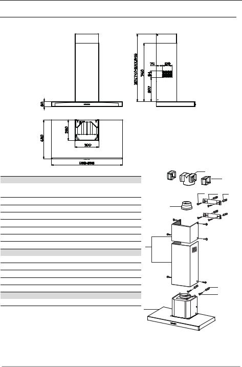
Ingombro
|
|
Componenti |
15 |
|
|
|
|
|
14.1 |
||
Rif. |
Q.tà |
Componenti di Prodotto |
|
||
|
|
|
|||
1 |
1 |
Corpo Cappa completo di: Comandi, Luce, Gruppo |
12a |
7.2.1 |
11 |
2 |
|
Ventilatore, Filtri |
|||
1 |
Camino Telescopico formato da: |
9 |
|
|
|
2.1 |
1 |
Camino Superiore |
|
|
|
|
|
|
|||
2.2 |
1 |
Camino Inferiore |
|
|
|
9 |
1 |
Flangia di Riduzione ø 150-120 mm |
|
|
|
14.1 |
2 |
Prolunga Raccordo Uscita Aria |
2.1 |
|
|
15 |
1 |
Raccordo Uscita Aria |
12c |
|
|
|
|
||||
Rif. |
Q.tà |
Componenti di Installazione |
2 |
|
|
7.2.1 |
2 |
Staffe Fissaggio Camino Superiore |
|
|
|
11 |
6 |
Tasselli |
2.2 |
|
|
12a |
6 |
Viti 4,2 x 44,4 |
|
|
|
12c |
6 |
Viti 2,9 x 9,5 |
|
|
|
|
Q.tà |
Documentazione |
|
11 |
|
|
1 |
Libretto Istruzioni |
|
|
|
|
|
12a |
|
||
|
|
|
|
|
|
|
|
|
1 |
|
|
IT |
|
5 |
|
5 |

INSTALLAZIONE
Foratura Parete e Fissaggio Staffe
7.2.1
11 116 116
12a
<![if ! IE]><![endif]>650 min.
<![endif]>320 X 1÷2
Tracciare sulla Parete:
•una linea Verticale fino al soffitto o al limite superiore, al centro della zona prevista per il montaggio della Cappa;
•una linea Orizzontale a: 650 mm min. sopra il Piano di Cottura.
•Appoggiare come indicato la Staffa 7.2.1 a 1-2 mm dal soffitto o dal limite superiore, allineando il suo centro (intagli) sulla linea Verticale di riferimento.
•Segnare i centri dei Fori della Staffa.
•Appoggiare come indicato la Staffa 7.2.1 a X mm sotto la prima staffa (X = altezza Camino Superiore in dotazione), allineando il suo centro (intagli) sulla linea Verticale di riferimento.
•Segnare i centri dei Fori della Staffa.
•Segnare come indicato, un punto di riferimento a 116 mm dalla linea Verticale di riferimento, e 320 mm sopra la linea Orizzontale di riferimento.
• Ripetere questa operazione dalla parte opposta.
•Forare ø 8 mm i punti segnati.
•Inserire i tasselli 11 nei fori.
•Fissare le Staffe, utilizzando le Viti 12a (4,2 x 44,4 ) in dotazione.
• Avvitare 2 Viti 12a (4,2 x 44,4) in dotazione nei fori per il fissaggio del corpo Cappa, lasciando uno spazio di 5-6 mm fra la parete e la testa della vite.
IT |
|
6 |
|
6 |

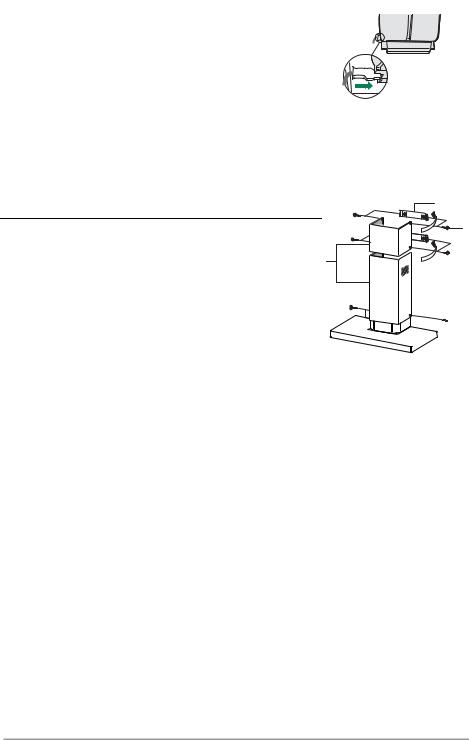
Montaggio Corpo Cappa
•Prima di agganciare il Corpo Cappa, serrare le 2 Viti Vr situate sui punti di aggancio del Corpo Cappa.
•Agganciare il Corpo Cappa alle Viti 12a.
•Serrare definitivamente le Viti 12a di supporto.
•Agire sulle Viti Vr per livellare il Corpo Cappa.
Vr
12a
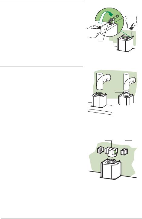
Connessioni
USCITA ARIA VERSIONE ASPIRANTE
Per installazione in Versione Aspirante collegare la Cappa alla tubazione di uscita per mezzo di un tubo
rigido o flessibile di ø150 o120 mm, la cui scelta è la- |
|
|
sciata all'installatore. |
|
|
• |
Per collegamento con tubo ø120 mm, inserire |
la |
|
Flangia di riduzione 9 sull’Uscita del Corpo Cappa. |
|
• Fissare il tubo con adeguate fascette stringitubo. |
Il |
|
|
materiale occorrente non è in dotazione. |
|
• |
Togliere eventuali FiltriAntiodore al Carbone attivo. |
|
USCITA ARIA VERSIONE FILTRANTE
•Inserire a pressione il Raccordo 15 sull’Uscita Aria.
•Inserire lateralmente le Prolunghe Raccordo14.1 sul Raccordo 15.
• Assicurarsi |
che |
l’uscita |
delle |
Prolunghe |
Raccordo |
|
14.1 risulti |
in |
corrispondenza |
delle bocchette |
del |
||
Camino sia |
in |
orizzontale |
che |
in verticale. |
Se |
così |
non fosse, aggiustare la posizione invertendo le Prolunghe Raccordo 14.1 e rimontare i particolari come prima descritto.
• Assicurarsi della presenza del Filtro Antiodore al Carbone attivo.
ø 150 |
ø 120 |
9
15 14.1
IT |
|
7 |
|
7 |
CONNESSIONE ELETTRICA
•Collegare la Cappall’Alimentazione di Rete interponendo un Interruttore bipolare con apertura dei contatti di almeno 3 mm.
•Rimuovere i Filtri antigrasso(vedi par. “Manutenzione”) e assicurarsi che il connettore del Cavo di alimentazione sia correttamente inserito nella presa dell’Aspiratore
Montaggio Camino
Camino superiore |
|
• Allargare leggermente le due falde laterali, |
agganciarle dietro |
le Staffe 7.2.1 e richiuderle fino a battuta. |
2 |
•Fissare lateralmente alle Staffe con 4 Viti12c (2,9 x 9,5) in dotazione.
7.2.1
2.1
2.2
Camino inferiore
• Allargare leggermente le due falde laterali del Camino, aggan-
ciarle tra il Camino superiore ela parete e richiuderle fino a


 battuta.

• Fissare lateralmente la parteinferiore al Corpo Cappa, con 2 Viti 12c (2,9 x 9,5) in dotazione.
12c
12c
IT |
|
8 |
|
8 |
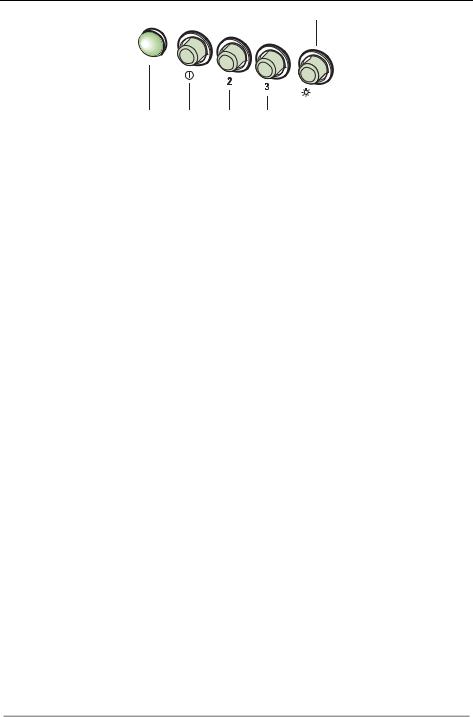
USO
L
|
|
S |
V1 |
V2 |
V3 |
|
|
|
|
|
|||
L |
Luci |
Accende e spegne l’Impianto di Illuminazione. |
|
|||
S |
Led |
Led accensione Motore. |
|
|
|
|
V1 |
Motore |
Accende e spegne il motore Aspirazione a velocità minima, adatta ad un |
|
|||
|
|
ricambio d’aria continuo particolarmente silenzioso, in presenza di pochi |
|
|||
|
|
vapori di cottura. |
|
|
|
|
V2 |
Velocità |
Velocità media, adatta alla maggior parte delle condizioni d’uso, dato |
|
|||
|
|
l’ottimo rapporto tra portata d’aria trattata e livello sonoro. |
|
|||
V3 |
Velocità |
Velocità massima, adatta a fronteggiare le massime emissioni di vapore di |
|
|||
|
|
cottura, anche per tempi prolungati. |
|
|||
IT |
|
9 |
|
9 |
MANUTENZIONE
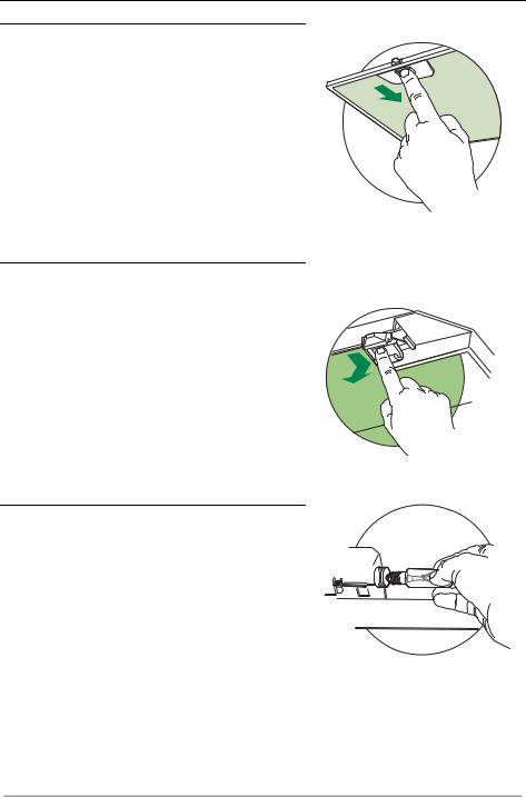
Filtri antigrasso
PULIZIA FILTRI ANTIGRASSO METALLICI AUTOPORTANTI
• Sono lavabili anche in lavastoviglie, e necessitano di essere lavati ogni 2 mesi circa di utilizzo o più frequentemente, per un uso particolarmente intenso.
• Togliere i Filtri uno alla volta, spingendoli verso la parte posteriore del gruppo e tirando contemporaneamente verso il basso.
• Lavare i Filtri evitando di piegarli, e lasciarli asciugare prima di rimontarli.
•Rimontarli facendo attenzione a mantenere la maniglia verso la parte visibile esterna.
Filtro antiodore (Versione Filtrante)
SOSTITUZIONE FILTRO ANTIODORE AL CARBONE ATTIVO
•Non è lavabile e non è rigenerabile, va sostituito almeno ogni 4 mesi o più frequentemente, per un uso
particolarmente intenso.
• Togliere i Filtri antigrasso metallici.
• Rimuovere il Filtro antiodore al Carbone attivo saturo, agendo sugli appositi agganci.
• Montare il nuovo Filtro agganciandolo nella sua sede.
• Rimontare i Filtri antigrasso metallici.
Illuminazione
SOSTITUZIONE LAMPADE
Lampade a incandescenza da 28 W
• Togliere i Filtri antigrasso metallici.
• Svitare le Lampade e sostituirle con nuove di uguali caratteristiche.
• Rimontare i Filtri antigrasso metallici.
IT |
|
1 |
|
10 |

RECOMMENDATIONS AND SUGGESTIONS
 The Instructions for Use apply to several versions of this appliance. Accordingly, you may find descriptions of individual features that do not apply to your specific appliance.
INSTALLATION
•The manufacturer will not be held liable for any damages resulting from incorrect or improper installation.
•The minimum safety distance between the cooker top and the extractor hood is 650 mm (some models can be installed at a lower height, please refer to the paragraphs on working dimensions and installation).
•Check that the mains voltage corresponds to that indicated on the rating plate fixed to the inside of the hood.
•For Class I appliances, check that the domestic power supply guarantees adequate earthing.
Connect the extractor to the exhaust flue through a pipe of minimum diameter 120 mm. The route of the flue must be as short as possible.
•Do not connect the extractor hood to exhaust ducts carrying combustion fumes (boilers, fireplaces, etc.).
•If the extractor is used in conjunction with non-electrical appliances (e.g. gas burning appliances), a sufficient degree of aeration must be guaranteed in the room in order to prevent the backflow of exhaust gas. The kitchen must have an opening communicating directly with the open air in order to guarantee the entry of clean air.
USE
• The extractor hood has been designed exclusively for domestic use to elimi- |
|
|
|
|
|
|
|
||
|
|
|
|
|
|
|
|||
nate kitchen smells. |
|
|
|
|
|
|
|
||
|
|
|
|
|
|
|
|||
• Never use the hood for purposes other than for which it has been designed. |
|
|
|
|
|||||
|
|
650 mm min. |
|||||||
• Never leave high naked flames under the hood when it is in operation. |
|
|
|
|
|
|
|
||
• Adjust the flame intensity to direct it onto the bottom of the pan only, making |
|
|
|
|
|
|
|
|
|
|
|
|
|
|
|
|
|
|
|
|
|
|
|
|
|
|
|
|
|
sure that it does not engulf the sides. |
|
|
|
|
|
|
|
||
•Deep fat fryers must be continuously monitored during use: overheated oil can burst into flames.
•Do not flambè under the range hood; risk of fire
•This appliance is not intended for use by persons (including children) with reduced physical, sensory or mental capabilities, or lack of experience and knowledge, unless they have been given supervision or instruction concerning use of the appliance by a person responsible for their safety.
•Children should be supervised to ensure that they do not play with the appli-
ance.
MAINTENANCE
• Switch off or unplug the appliance from the mains supply before carrying out any maintenance work.
•Clean and/or replace the Filters after the specified time period (Fire hazard).
•Clean the hood using a damp cloth and a neutral liquid detergent.
The symbol  on the product or on its packaging indicates that this product may not be treated as household waste. Instead it shall be handed over to the applicable collection point for the recycling of electrical and electronic equipment. By ensuring this product is disposed of correctly, you will help prevent potential negative consequences for the environment and human health, which could otherwise be caused by inappropriate waste handling of this product. For more detailed information about recycling of this product, please contact your local city office, your household waste disposal service or the shop where you purchased the product.
EN |
|
1 |
|
11 |

CHARACTERISTICS
Dimensions
|
|
Components |
15 |
|
|
|
|
|
14.1 |
||
Ref. |
Q.ty |
Product Components |
|
||
|
|
|
|||
1 |
1 |
Hood Body, complete with: Controls, Light, Blower, |
12a |
7.2.1 |
11 |
2 |
|
Filters |
|||
1 |
Telescopic Chimney comprising: |
9 |
|
|
|
2.1 |
1 |
Upper Section |
|
|
|
|
|
|
|||
2.2 |
1 |
Lower Section |
|
|
|
9 |
1 |
Reducer Flange ø 150-120 mm |
|
|
|
14.1 |
2 |
Air Outlet Connection Extension |
2.1 |
|
|
15 |
1 |
Air Outlet Connection |
12c |
|
|
|
|
||||
|
|
|
2 |
|
|
Ref. |
Q.ty |
Installation Components |
|
|
|
7.2.1 |
2 |
Upper Chimney Section Fixing Brackets |
2.2 |
|
|
11 |
6 |
Wall Plugs |
|
|
|
12a |
6 |
Screws 4,2 x 44,4 |
|
|
|
12c |
6 |
Screws 2,9 x 9,5 |
|
11 |
|
|
|
|
|
|
|
|
Q.ty |
Documentation |
|
12a |
|
|
|
|
|
||
|
1 |
Instruction Manual |
1 |
|
|
|
|
|
|
|
|
EN |
|
1 |
|
12 |

INSTALLATION
Wall drilling and bracket fixing
7.2.1
11 116 116
12a
<![if ! IE]><![endif]>650 min.
<![endif]>320 X 1÷2
Wall marking:
•Draw a vertical line on the supporting wall up tothe ceiling, or as high as practical, at the centre of the area in which the hood will be installed.
•Draw a horizontal line at 650mm above the hob. Place bracket7.2.1 on the wall as shown about 1-2 mm from the ceiling or upper limit aligning the centre (notch) with the vertical reference line.
•Mark the wall at the centres of the holes in the bracket.
•Place bracket 7.2.1 on the wall as shown at X mm below the first bracket (X = height of the upper chimney section supplied), aligning the centre (notch) with the vertical line.
•Mark the wall at the centres of the holes in the bracket.
•Mark a reference point as indicated at 116mm from the vertical reference line and 320 mm above the horizontal reference line.
•Repeat this operation on the other side.
•Drill ø 8 mm holes at all the centre points marked.
•Insert the wall plugs 11 in the holes.
•Fix the brackets using the 12a (4,2 x 44,4) screws supplied.
• Insert the two screws 12a (4,2 x 44,4) supplied in the hood body fixing holes, leaving a gap of 5-6 mm between the wall and the head of the screw.
EN |
|
1 |
|
13 |

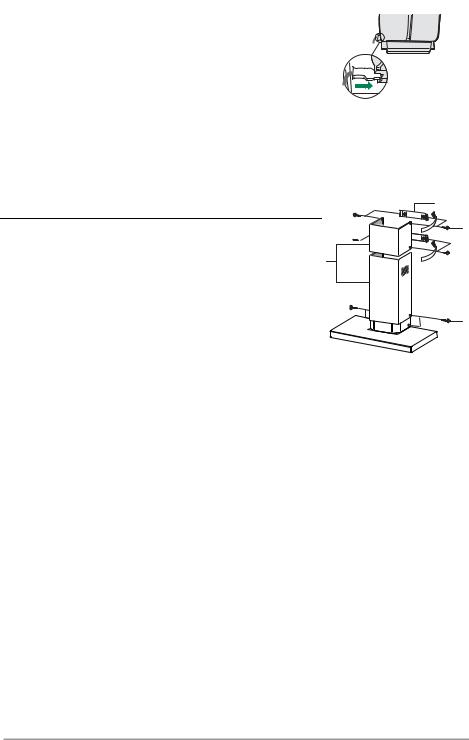
Mounting the hood body
• Before attaching the hood body, tighten the two screws Vr located on the hood body mounting points.
•Hook the hood body onto the screws 12a.
•Fully tighten the support screws 12a.
•Adjust the screws Vr to level the hood body.
Vr
12a
Connections
DUCTED VERSION AIR EXHAUST SYSTEM
When installing the ducted version, connect the hood to the chimney using either a flexible or rigid pipe ø 150 or 120 mm, the choice of which is left to the installer.
•To install a ø 120 mm airexhaust connection, insert the reducer flange 9 on the hood body outlet.
•Fix the pipe in position using sufficient pipe clamps (not supplied).
•Remove possible charcoal filters.
RECIRCULATION VERSION AIR OUTLET
• Push fit connection 15 onto the hood body outlet.
• Insert the connection extension pieces laterally14.1 in connection 15.
•Make sure that the outlet of the extension pieces14.1 is horizontally and verticaly aligned with the chimney outlets. If this is not the case, adjust the position by either reversing the connection extension pieces 14.1 and then reassemble as described previously.
•Ensure that the activated charcoal filters have been inserted.
ø 150 |
ø 120 |
9
15 14.1
EN |
|
1 |
|
14 |
ELECTRICAL CONNECTION
• Connect the hood to the mains through a two-pole switch having a contact gap of at least 3 mm.
• Remove the grease filters (see paragraph Maintenance) being sure that the connector of the feeding cable is correctly inserted in the socket placed on the side of the fan.
7.2.1
Chimney assembly
12c
Upper exhaust Chimney
• Slightly widen the two sides of the upper chimney and hook2.1 
 them behind the brackets 7.2.1, making sure that they are well 2
seated. 2.2
• Secure the sides to the brackets using the 4 screws12c (2,9 x 9,5) supplied.
12c
Lower exhaust Chimney
• Slightly widen the two sides of the chimney and hook them between the upper chimney and the wall, making sure that they are well seated.
•Fix the lower part laterally to the hood body using the 2 screws 12c (2,9 x 9,5) supplied.
EN |
|
1 |
|
15 |

USE
L
|
|
S |
V1 |
V2 |
V3 |
||
|
|
|
|
|
|||
L |
Light |
Switches the lighting system on and off. |
|||||
S |
Led |
Motor running led. |
|
|
|
|
|
V1 |
Motor |
Switches the extractor motor on and off at low speed. Used to provide a |
|||||
|
|
contin-uos and silent air change in the presence of light cooking vapours. |
|
||||
V2 |
Speed |
Medium speed, suitable for most operating conditions given the optimum |
|||||
|
|
treated air flox/noise level ratio. |
|
|
|
||
V3 |
Intensive |
Maximum speed, used for eliminating the highest cooking vapour emission, |
|
||||
|
|
including long periods. |
|
|
|
|
|
EN |
|
1 |
|
16 |
MAINTENANCE
Grease filters
CLEANING METAL SELFSUPPORTING GREASE FILTERS
• The filters must be cleaned every 2 months of operation, or more frequently for particularly heavy usage, and can be washed in a dishwasher.
• Remove the filters one at a time by pushing them towards the back of the group and pulling down at the same time.
• Wash the filters, taking care not to bend them. Allow them to dry before refitting.
•When refitting the filters,make sure that the handle is visible on the outside.
Activated charcoal filter (Recirculation version)
REPLACING THE ACTIVATED CHARCOAL FILTER
•The filter is not washable and cannot be regenerated, and must be replaced approximately every 4 months
|
of operation, or more quentlyfre for particularly |
|
heavy usage. |
• |
Remove the metal grease filters. |
• |
Remove the saturated activated carbon filter by re- |
|
leasing the fixing hooks. |
•Fit the new filter by hooking it into its seating.
•Refit the metal grease filters.
Lighting
LIGHT REPLACEMENT
28 W incandescent light.
• Remove the metal grease filters.
• Unscrew the bulbs and replace them with new ones having the same characteristics.
• Replace the metal grease filters.
EN |
|
1 |
|
17 |

EMPFEHLUNGEN UND HINWEISE
 Diese Gebrauchsanleitung gilt für mehrere Geräte-Ausführungen. Es ist möglich, dass einzelne Ausstattungsmerkmale beschrieben sind, die nicht auf Ihr Gerät zutreffen.
MONTAGE
•Der Hersteller haftet nicht für Schäden, die auf eine fehlerhafte und unsachgemäße Montage zurückzuführen sind.
•Der minimale Sicherheitsabstand zwischen Kochmulde und Haube muss 650 mm betragen (einige Modelle können an einer geringeren Höhe installiert werden, beziehen Sie sich dazu auf den Absatz Raumbedarf und Installation).
•Prüfen, ob die Netzspannung mit dem Wert auf dem im Haubeninneren angebrachten Schild übereinstimmt.
•Bei Geräten der Klasse I ist sicherzustellen, dass die elektrische Anlage des Wohnhauses über eine vorschriftsmäßige Erdung verfügt.
•Das Anschlussrohr der Haube zur Luftaustrittsöffnung muss einen Durchmesser von 120 mm oder darüber aufweisen. Der Rohrverlauf muss so kurz wie möglich sein.
•Die Haube darf an keine Entlüftungsschächte angeschlossen werden, in die Verbrennungsgase (Heizkessel, Kamine usw.) geleitet werden.
•Werden im Raum außer der Dunstabzugshaube andere, nicht elektrisch betriebene (z.B. gasbetriebene) Geräte verwendet, muss für eine ausreichende Belüftung gesorgt werden. Sollte die Küche diesbezüglich nicht entsprechen, ist an einer Aussenwand eine Öffnung anzubringen, die Frischluftzufuhr gewährleistet.
BEDIENUNG
• Die Dunstabzugshaube ist ausschließlich zum Einsatz im privaten Haushalt und zur Beseitigung von Küchengerüchen vorgesehen.
• Unsachgemäßer Einsatz der Haube ist zu unterlassen. |
|
|
|
|
|
|
|
||
• Große Flammen bei eingeschalteter Haube niemals unbedeckt lassen. |
|
|
|
|
|
|
|
||
• Die Intensivität der Flamme ist so zu regulieren, dass sie den Topfboden nicht über- |
|
|
|
|
|
|
|
||
|
|
|
|
|
|
|
|||
ragt. |
|
|
|
|
|||||
|
|
650 mm min. |
|||||||
• Frittiergeräte müssen während des Gebrauchs stets beaufsichtigt werden: überhitztes |
|
|
|
|
|
|
|
||
Öl kann sich entzünden. |
|
|
|
|
|
|
|
|
|
|
|
|
|
|
|
|
|
|
|
|
|
|
|
|
|
|
|
|
|
•Keine flambierten Speisen unter der Abzugshaube zubereiten: Brandgefahr.
•Dieses Gerät darf nicht von Personen, auch Kindern, mit verminderten psychischen, sensorischen und geistigern Fähigkeiten, oder von Personen ohne Erfahrung und Kenntnisse benutzt werden, sofern sie nicht von für ihre Sicherheit verantwortlichen Personen beaufsichtigt und beim Gebrauch des Geräts angeleitet werden.
•Kinder dürfen sich nicht unbeaufsichtigt in der Nähe des Geräts aufhalten und auf keinen Fall mit dem Gerät spielen.
WARTUNG
• Bevor Wartungsarbeiten durchgeführt werden, muss die Stromzufuhr zur Haube unterbrochen werden, indem der Stecker gezogen oder der Hauptschalter abgeschaltet wird.
• Bei der Filterwartung müssen die vom Hersteller empfohlenen Zeiträume zum Austauschen der Filter genauestens eingehalten werden (Brandgefahr).
•Zur Reinigung der Haubenflächen Wir empfehlen ein feuchtes Tuch und ein mildes Flüssigreinigungsmittel.
Das Symbol  auf dem Produkt oder seiner Verpackung weist darauf hin, dass dieses Produkt nicht als normaler Haushaltsabfall zu behandeln ist, sondern an einem Sammelpunkt für das Recycling von elektrischen und elektronischen Geräten abgegeben werden muss. Durch Ihren Beitrag zum korrekten Entsorgen dieses Produkts schützen Sie die Umwelt und die Gesundheit Ihrer Mitmenschen. Umwelt und Gesundheit werden durch falsches Entsorgen gefährdet. Weitere Informationen über das Recycling dieses Produkts erhalten Sie von Ihrem Rathaus, Ihrer Müllabfuhr oder dem Geschäft, in dem Sie das Produkt gekauft haben.
DE |
|
1 |
|
18 |
CHARAKTERISTIKEN
Platzbedarf
|
|
Komponenten |
15 |
|
|
|
|
|
14.1 |
||
Pos. |
St. |
Produktkomponenten |
|
||
|
|
|
|||
1 |
1 |
Haubenkörper mit Schaltern,Beleuchtung, |
12a |
7.2.1 |
11 |
|
|
Gebläsegruppe,Filter |
|||
|
|
|
|
|
|
2 |
1 |
Teleskopkamin bestehend aus: |
|
9 |
|
2.1 |
1 |
oberer Kaminteil |
|
||
|
|
||||
2.2 |
1 |
unterer Kaminteil |
|
|
|
9 |
1 |
Reduzierflansch ø 150-120 mm |
|
|
|
14.1 |
2 |
Verlängerung Luftaustritt-Anschlussstück |
2.1 |
12c |
|
15 |
1 |
Luftaustritt-Anschlussstück |
|||
2 |
|||||
|
|
|
|
||
Pos. |
St. |
Montagekomponenten |
|
|
|
7.2.1 |
2 |
Befestigungsbügel oberer Kaminteil |
2.2 |
|
|
11 |
6 |
Bügel |
|
|
|
12a |
6 |
Schrauben 4,2 x 44,4 |
|
|
|
12c |
6 |
Schrauben 2,9 x 9,5 |
|
11 |
|
|
|
|
|
||
|
St. |
Dokumentation |
|
12a |
|
|
|
|
|||
|
1 |
Bedienungsanleitung |
1 |
|
|
|
|
|
|
DE |
|
1 |
|
19 |
MONTAGE
Bohren der Befestigungslöcher und Fixieren der Befestigungsbügel
7.2.1
11 116 116
12a
<![if ! IE]><![endif]>650 min.
<![endif]>320 X 1÷2
Nachstehende Linien an die Wand zeichnen:
•eine vertikale Linie bis zurDecke oder oberen Begrenzung, und zwar in der Mitte des Bereiches, in dem die Haube montiert werden soll;
•eine horizontale Linie mit einem minimalen Abstand von 650 mm zur Kochfläche.
•Einen Bügel 7.2.1 zirka 1-2 mm unter der Decke oder oberen Begrenzung an die Wand legen und seinen Mittelpunkt (Einschnitte) auf die vertikale Bezugslinie ausrichten.
•Die Mitte der beiden Bügellöcher an der Wand markieren.
•Den zweiten Bügel 7.2.1 an die Wand legen, wobei ein Abstand X mm vom oberen Bügel einzuhalten ist (X = Höhe des jeweiligen oberen Kaminteils); den Mittelpunkt (Einschnitte) auf die vertikale Bezugslinie ausrichten.
•Die Mitte der Bügellöcher an der Wand markieren.
•Wie beschrieben einen Bezugspunkt 116 mm von der vertikalen Bezugslinie und 320 mm oberhalb der horizontalen Bezugslinie kennzeichnen.
•Gleichermaßen an der gegenüberliegenden Seite vorgehen.
•Mit einem Bohrer ø 8 mm die markierten Punkte bohren.
•Die Dübel 11 in die Bohrungen einfügen.
•Die Bügel mit den mitgelieferten Schrauben 12a (4,2 x 44,4) fixieren.
•2 der mitgelieferten Schrauben12a (4,2 x 44,4) bei den Befestigungslöchern des Haubenkörpers einschrauben, wobei zwischen Wand und Schraubenkopf ein Freiraum von 5-6 mm zu belassen ist.
DE |
|
2 |
|
20 |
Montage des Haubenkörpers
• Bevor der Haubenkörper eingehakt wird, die 2 Schrauben Vr bei den Haubenkörper-Anhakpunkten festziehen.
•Den Haubenkörper bei den Schrauben 12a einhängen.
•Die Halteschrauben 12a definitiv festziehen.
•Den Haubenkörper mit Hilfe der SchraubenVr ausrichten.
Vr
12a
Anschlüss in abluftversion
Bei Abluftbetrieb kann die Haube vom Installateur wahlweise mittels Rohr oder Schlauch (ø 150 oder 120 mm) an die Außenrohrleitung angeschlossen werden.
•Bei Verwendung eines Anschlussrohres ø 120 den Reduzierflansch 9 am Haubenaustritt anbringen.
•Das Rohr mit geeigneten Rohrschellen fixieren. Das hierzu erforderliche Material wird nicht mitgeliefert.
•Eventuell vorhandene Aktivkohlefilter entnehmen.
ANSCHLUSS IN UMLUFTVERSION
•Den Anschluss 15 beim Luftaustritt des Haubenkörpers eindrücken.
•Die Verlängerungen 14.1 beim Anschluss 15 seitlich einfügen.
•Überprüfen, ob die Verlängerungen 14.1 mit den ent-
sprechenden Kaminstutzen sowohl horizontal wie auch vertikal übereinstimmen. Sollte dies nicht der Fall sein, müssen die Verlängerungen14.1 miteinander vertauscht und wie zuvor beschrieben wieder zusammengebaut werden.
•Kontrollieren, ob der Aktivkohle-Geruchsfilter vorhanden ist.
ø 150 |
ø 120 |
9
15 14.1
DE |
|
2 |
|
21 |

ELEKTROANSCHLUSS
• Bei Anschluss der Haube an das Stromnetz muss ein zweipoliger Schalter mit einem Öffnungsweg von mindestens 3 mm zwischengeschaltet werden.
• Entfernen Sie die Fettfilter (s. Abschnitt „Wartung“) und versichern Sie sich, daß die Kabelverbindung in die Steckdose des Gebläses einwandfrei eingesteckt wird.
Kaminmontage
Oberer Kaminteil |
|
|
• Die beiden seitlichen Schenkel leicht auseinanderbiegen, hinter |
2.1 |
|
den Bügeln 7.2.1 einhängen und bis zum Anschlag wieder |
|
|
2 |
|
|
schließen. |
2.2 |
|
• Bei den Bügeln mit Hilfe der 4 mitgelieferten Schrauben12c |
||
|
||
fixieren. |
|
Unterer Kaminteil
• Die beiden seitlichen Schenkel des Kaminteils leicht auseinanderbiegen, zwischen dem oberen Kaminteil und der Wand einhängen und bis zum Anschlag wieder schließen.
•Den unteren Teil seitlich amHaubenkörper mit 2 der mitgelieferten Schrauben 12c fixieren.
7.2.1
12c
12c
DE |
|
2 |
|
22 |
 Loading...