


ASUS P65UP5 User Manual

R
P/I P65UP5
Baseboard for CPU Cards
USER’S MANUAL

USER'S NOTICE
No part of this manual, including the products and softwares described in it, may be reproduced, transmitted, transcribed, stored in a retrieval system, or translated into any language
in any form or by any means, except documentation kept by the purchaser for backup purposes, without the express written permission of ASUSTeK COMPUTER INC. (“ASUS”).
ASUS PROVIDES THIS MANUAL “AS IS” WITHOUT WARRANTY OF ANY KIND,
EITHER EXPRESS OR IMPLIED, INCLUDING BUT NOT LIMITED TO THE IMPLIED
W ARRANTIES OR CONDITIONS OF MERCHANTABILITY OR FITNESS FOR A PARTICULAR PURPOSE. IN NO EVENT SHALL ASUS, ITS DIRECTORS, OFFICERS,
EMPLOYEES OR AGENTS BE LIABLE FOR ANY INDIRECT, SPECIAL, INCIDENTAL, OR CONSEQUENTIAL DAMAGES (INCLUDING DAMAGES FOR LOSS OF
PROFITS, LOSS OF BUSINESS, LOSS OF USE OR DAT A, INTERRUPTION OF BUSINESS AND THE LIKE), EVEN IF ASUS HAS BEEN ADVISED OF THE POSSIBILITY
OF SUCH DAMAGES ARISING FROM ANY DEFECT OR ERROR IN THIS MANUAL
OR PRODUCT.
Products and corporate names appearing in this manual may or may not be registered trademarks or copyrights of their respective companies, and are used only for identification or
explanation and to the owners’ benefit, without intent to infringe.
• Intel, LANDesk, and Pentium are registered trademarks of Intel Corporation.
• IBM and OS/2 are registered trademarks of International Business Machines.
• Symbios is a registered trademark of Symbios Logic Corporation.
• Windows and MS-DOS are registered trademarks of Microsoft Corporation.
• Sound Blaster AWE32 and SB16 are trademarks of Creative Technology Ltd.
• Adobe and Acrobat are registered trademarks of Adobe Systems Incorporated.
The product name and revision number are both printed on the board itself. Manual revisions
are released for each board design represented by the digit before and after the period of the
manual revision number. Manual updates are represented by the third digit in the manual
revision number.
For previous or updated manuals, BIOS, drivers, or product release information, contact ASUS
at http://www.asus.com.tw or through any of the means indicated on the following page.
SPECIFICATIONS AND INFORMATION CONTAINED IN THIS MANUAL ARE FURNISHED FOR INFORMATIONAL USE ONLY, AND ARE SUBJECT TO CHANGE AT
ANY TIME WITHOUT NOTICE, AND SHOULD NOT BE CONSTRUED AS A COMMITMENT BY ASUS. ASUS ASSUMES NO RESPONSIBLITY OR LIABILITY FOR
ANY ERRORS OR INACCURACIES THAT MA Y APPEAR IN THIS MANUAL, INCLUDING THE PRODUCTS AND SOFTWARES DESCRIBED IN IT.
Copyright © 1997 ASUSTeK COMPUTER INC. All Rights Reserved.
Product Name: P/I-P65UP5
Manual Revision: 2.04
Release Date: July 1997
2
ASUS P/I-P65UP5 User’s Manual

ASUS CONTACT INFORMATION
ASUSTeK COMPUTER INC.
Marketing Info
Address: 150 Li-Te Road, Peitou, Taipei, Taiwan 112, ROC
Telephone: +886-2-894-3447
Fax: +886-2-894-3449
Email: info@asus.com.tw
Technical Support
Fax: +886-2-895-9254
BBS: +886-2-896-4667
Email: tsd@asus.com.tw
WWW: www.asus.com.tw
Gopher: gopher.asus.com.tw
FTP: ftp.asus.com.tw/pub/ASUS
ASUS COMPUTER INTERNATIONAL
Marketing Info
Address: 721 Charcot Avenue, San Jose, CA 95131, USA
Telephone: +1-408-474-0567
Fax: +1-408-474-0568
Email: info-usa@asus.com.tw
Technical Support
BBS: +1-408-474-0569
Email: tsd-usa@asus.com.tw
WWW: www.asus.com
ASUS COMPUTER GmbH
Marketing Info
Address: Harkort Str. 25, 40880 Ratingen, BRD, Germany
Telephone: 49-2102-445011
Fax: 49-2102-442066
Email: info-ger@asus.com.tw
Technical Support
BBS: 49-2102-448690
Email: tsd-ger@asus.com.tw
Hotline: 49-2102-499712
ASUS P/I-P65UP5 User’s Manual 3

CONTENTS
I. INTRODUCTION.........................................................7
How this Manual is Organized ........................................................7
Item Checklist ..................................................................................7
Features of the ASUS P/I-P65UP5 Baseboard ................................8
II. FEATURES ..................................................................8
Parts of the ASUS Baseboard ..........................................................9
III. INSTALLATION .....................................................10
ASUS Baseboard Layout ...............................................................10
Installation Steps............................................................................12
1. Jumpers ......................................................................................12
Jumper Settings ..................................................................13
2. System Memory (DRAM/SDRAM & SRAM) ........................16
DRAM Memory Installation Procedures............................17
3. Central Processing Unit ............................................................18
System Case........................................................................18
4. Expansion Cards .......................................................................20
Expansion Card Installation Procedure ..............................20
Assigning IRQs for Expansion Cards.................................20
Assigning DMA Channels for ISA Cards...........................21
5. External Connectors..................................................................22
IV. ASUS PCI SCSI Cards ............................................28
Symbios SCSI BIOS and Drivers ..................................................28
ASUS PCI-SC200 & PCI-SC860 SCSI Cards ..............................28
Setting Up the ASUS PCI-SC200 & PCI-SC860 .....................29
Setting the INT Assignment for the ASUS PCI-SC200 ...........29
Terminator Requirements for SCSI Devices ............................29
Terminator Settings for the ASUS PCI-SC860 ........................30
Terminator Settings for the ASUS PCI-SC200 ........................30
SCSI ID Numbers for SCSI Devices .......................................31
SCSI ID Priority .......................................................................31
V. ASUS I-A16C Audio Card........................................32
ASUS I-A16C Audio Features .................................................32
Layout and Connectors ............................................................32
Connectors ..........................................................................32
CD-Audio Connector Pin Definitions ......................................32
4
ASUS P/I-P65UP5 User’s Manual

(This page was intentionally left blank.)
ASUS P/I-P65UP5 User’s Manual 5

FCC & DOC COMPLIANCE
Federal Communications Commission Statement
This device complies with FCC Rules Part 15. Operation is subject to the following
two conditions:
• This device may not cause harmful interference, and
• This device must accept any interference received, including
interference that may cause undesired operation.
This equipment has been tested and found to comply with the limits for a Class B
digital device, pursuant to Part 15 of the FCC Rules. These limits are designed to
provide reasonable protection against harmful interference in a residential installation. This equipment generates, uses and can radiate radio frequency energy and, if
not installed and used in accordance with manufacturer's instructions, may cause
harmful interference to radio communications. However, there is no guarantee that
interference will not occur in a particular installation. If this equipment does cause
harmful interference to radio or television reception, which can be determined by
turning the equipment off and on, the user is encouraged to try to correct the interference by one or more of the following measures:
• Re-orient or relocate the receiving antenna.
• Increase the separation between the equipment and receiver.
• Connect the equipment to an outlet on a circuit different from
that to which the receiver is connected.
• Consult the dealer or an experienced radio/TV technician for help.
WARNING! The use of shielded cables for connection of the monitor to the
graphics card is required to assure compliance with FCC regulations. Changes
or modifications to this unit not expressly approved by the party responsible for
compliance could void the user's authority to operate this equipment.
Canadian Department of Communications Statement
This digital apparatus does not exceed the Class B limits for radio noise emissions
from digital apparatus set out in the Radio Interference Regulations of the Canadian Department of Communications.
6
ASUS P/I-P65UP5 User’s Manual

I. INTRODUCTION
How this Manual is Organized
This manual is divided into the following sections:
I. Introduction: Manual information and checklist
II. Features: Information and specifications concerning this product
III.Installation: Instructions on setting up the baseboard
IV. SCSI Cards: Installation of ASUS SCSI cards (optional)
Item Checklist
Please check that your package is complete. If you discover damaged or missing
items, please contact your retailer.
þ ASUS P/I-P65UP5 baseboard
þ C-P6ND, C-P55T2D, or C-PKND CPU card
þ 2 serial port ribbon cables attached to a mounting bracket
I. INTRODUCTION
(Manual / Checklist)
þ 1 parallel ribbon cable with mounting bracket
þ 1 IDE ribbon cable
þ 1 floppy ribbon cable
þ This user’s manual
¨ Infrared module (optional)
¨ USB cable with mounting bracket set (optional)
¨ ASUS PCI-SC200 Fast SCSI or PCI-SC860 Ultra-Fast SCSI card (optional)
¨ ASUS I-A16C audio card and manual* (optional)
*
Online help is provided with the Creative 16X audio drivers. A separate manual is
provided for the Creative 16C Series audio drivers.
ASUS P/I-P65UP5 User’s Manual 7

II. FEATURES
Features of the ASUS P/I-P65UP5 Baseboard
The P/I-P65UP5 is carefully designed for the demanding PC user who wants great
versatility in a computer system. This baseboard:
• Easy Installation: Is equipped with BIOS that supports autodetection of hard
drives and Plug and Play to make setup of hard drives and expansion cards
virtually automatic.
II. FEATURES
(Features)
• Desktop Management Interface (DMI): Supports DMI through BIOS, which
allows hardware to communicate within a standard protocol creating a higher
level of compatibility. (Requires DMI-enabled components.)
• Versatile Processor Support: Supports dual 75–233MHz Pentium, 150–
200MHz Pentium Pro, 233–333MHz Pentium II processors.
• Versatile DRAM Memory Support: Supports eight 72-pin SIMMs of 4MB,
8MB, 16MB, 32MB, 64MB to form a memory size between 8MB to 512MB.
Supports both Fast Page Mode (FPM), and Extended Data Output (EDO) SIMMs.
Burst Extended Data Output (BEDO) supported with the C-P6ND CPU card.
• ISA and PCI Expansion Slots: Provides three 16-bit ISA slots, four 32-bit PCI slots, and
one PCI/MediaBus shared slot for either a standard PCI card or ASUS MediaBus Card.
• ASUS MediaBus: Features an expansion slot extension shared with PCI Slot 5
for an optional high-performance expansion card, which includes two functions
in one easy-to-install card.
• Super Multi-I/O: Provides two high-speed UART-compatible serial ports and
one parallel port with EPP and ECP capabilities. Supports two of either 5.25- or
3.5-inch disk drives (1.44MB or 2.88MB) without an external card.
• PCI Bus Master IDE Controller: Comes with an onboard PCI Bus Master
IDE controller with two connectors that supports four IDE devices in two channels, supports PIO Modes 3 and 4 and Bus Master IDE DMA Mode 2, and
supports Enhanced IDE devices such as Tape Backup and CD-ROM drives.
Supports Japanese standard “Floppy 3 mode” (3.5-inch disk drive: 1.2MB)
and LS-120 floppy disk drives (3.5-inch disk drive: 120 MB, 1.44MB, 720K).
BIOS supports IDE CD-ROM or SCSI device boot-up.
• Optional IrDA Module: Supports an optional infrared port module for wireless
file transfers and communication.
• SCSI BIOS: Supports optional ASUS SCSI controller cards through onboard firmware.
• Intelligence: Supports Fan Status Monitoring and Alarm, Temperature Moni-
toring and Alert, Voltage Monitoring and Alert, System Resources Alert, and
Virus Write Protection through the optional onboard LM78 Hardware Monitor
and Intel
8 ASUS P/I-P65UP5 User’s Manual
®
LANDesk Client Manager (LDCM) software.
II. FEATURES
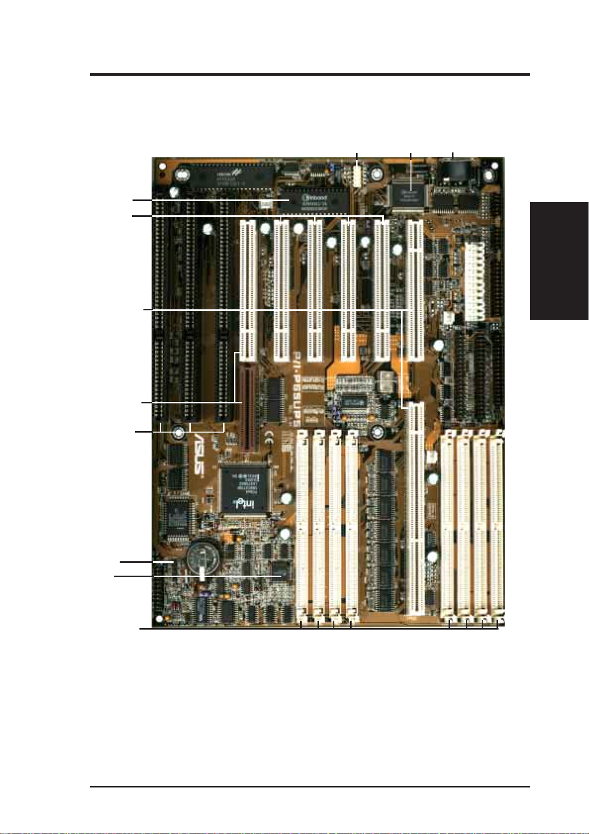
Parts of the ASUS Baseboard
Programmable
Flash ROM
4 PCI Slots
CPU Card Slot
PCI 5 or ASUS
MediaBus
Universal
Serial Bus
Super
Multi-I/O
Keyboard
II. FEATURES
(Parts of Board)
3 ISA Slots
Infrared Module
Support
LM78
Hardware Monitor
(Optional)
(8) 72-pin
SIMM Sockets
ASUS P/I-P65UP5 User’s Manual 9
III. INSTALLATION
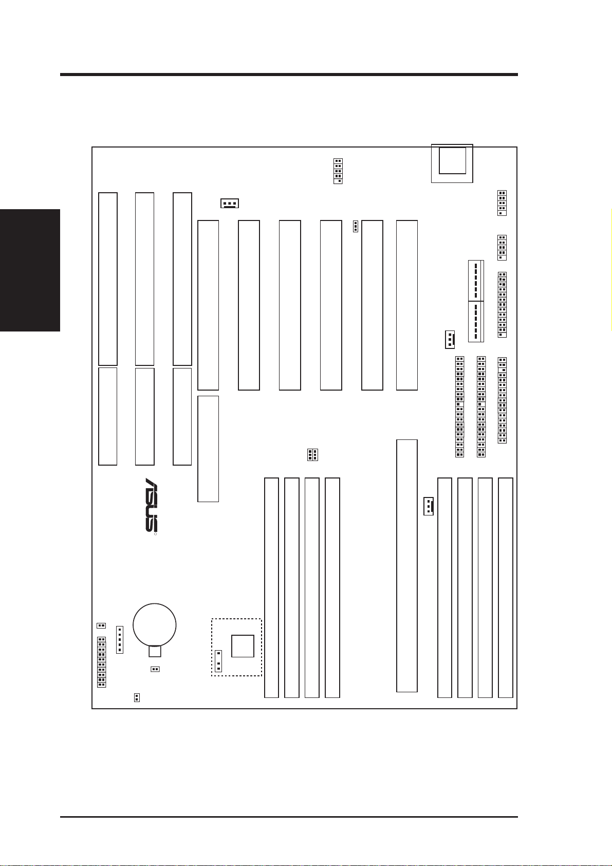
ASUS Baseboard Layout
Keyboard
III. INSTALLATION
(Board Layout)
ISA Slot 3
ISA Slot 2
ISA Slot 1
FANPWR3
PCI Slot 5 / MediaBus
PCI Slot 4
Universal Serial Bus
PCI Slot 3
JP2
JP3
BUS Freq.
JP1
PCI Slot 2
Multi-i/O Enable/Disable
PCI Slot 1
CPU Card Slot
FANPWR1
CPU Card Slot
COM 1
COM 2
Board Power Input
P9 P8
Secondary IDE
Primary IDE
Serial Ports
Parallel Port
Floppy Drives
SIMM Socket 2 (Bank 0)
SIMM Socket 4 (Bank 1)
SIMM Socket 6 (Bank 2)
IDE LED
Case Connector
CR2032 3Volts
Lithium Cell
Infrared Con
BIOS Power
JP9
Battery Test
JP7
RTC RAM
Operation/Clear CMOS
SIMM Socket 8 (Bank 3)
R
Hardware
Monitor
LM78
Chassis Conn.
SIMM Socket 1 (Bank 0)
SIMM Socket 3 (Bank 1)
SIMM Socket 5 (Bank 2)
FANPWR2
SIMM Socket 7 (Bank 3)
The items in outline are only available on the baseboard with onboard LM78 Hardware Monitor.
10 ASUS P/I-P65UP5 User’s Manual
 Loading...