


ASUS P5N-E SLI User Manual

Motherboard
P5N-E SLI
ii
E2968
First Edition V2
December 2006
Copyright © 2006 ASUSTeK COMPUTER INC. All Rights Reserved.
No part of this manual, including the products and software described in it, may be reproduced,
transmitted, transcribed, stored in a retrieval system, or translated into any language in any form
or by any means, except documentation kept by the purchaser for backup purposes, without the
express written permission of ASUSTeK COMPUTER INC. (“ASUS”).
Product warranty or service will not be extended if: (1) the product is repaired, modied or
altered, unless such repair, modication of alteration is authorized in writing by ASUS; or (2)
the serial number of the product is defaced or missing.
ASUS PROVIDES THIS MANUAL “AS IS” WITHOUT WARRANTY OF ANY KIND, EITHER
EXPRESS OR IMPLIED, INCLUDING BUT NOT LIMITED TO THE IMPLIED WARRANTIES
OR CONDITIONS OF MERCHANTABILITY OR FITNESS FOR A PARTICULAR PURPOSE.
IN NO EVENT SHALL ASUS, ITS DIRECTORS, OFFICERS, EMPLOYEES OR AGENTS BE
LIABLE FOR ANY INDIRECT, SPECIAL, INCIDENTAL, OR CONSEQUENTIAL DAMAGES
(INCLUDING DAMAGES FOR LOSS OF PROFITS, LOSS OF BUSINESS, LOSS OF USE
OR DATA, INTERRUPTION OF BUSINESS AND THE LIKE), EVEN IF ASUS HAS BEEN
ADVISED OF THE POSSIBILITY OF SUCH DAMAGES ARISING FROM ANY DEFECT OR
ERROR IN THIS MANUAL OR PRODUCT.
SPECIFICATIONS AND INFORMATION CONTAINED IN THIS MANUAL ARE FURNISHED
FOR INFORMATIONAL USE ONLY, AND ARE SUBJECT TO CHANGE AT ANY TIME
WITHOUT NOTICE, AND SHOULD NOT BE CONSTRUED AS A COMMITMENT BY
ASUS. ASUS ASSUMES NO RESPONSIBILITY OR LIABILITY FOR ANY ERRORS OR
INACCURACIES THAT MAY APPEAR IN THIS MANUAL, INCLUDING THE PRODUCTS
AND SOFTWARE DESCRIBED IN IT.
Products and corporate names appearing in this manual may or may not be registered
trademarks or copyrights of their respective companies, and are used only for identication or
explanation and to the owners’ benet, without intent to infringe.

iii
Contents
Notices ................................................................................................vii
Safety information .............................................................................viii
About this guide .................................................................................. ix
How this guide is organized ..................................................... ix
Where to nd more information .............................................. ix
Conventions used in this guide ................................................. x
Typography ............................................................................... x
P5N-E SLI specications summary ...................................................... xi
Chapter 1: Product introduction
1.1 Welcome! .............................................................................. 1-2
1.2 Package contents ................................................................. 1-2
1.3 Special features .................................................................... 1-3
1.3.1 Product highlights ................................................... 1-3
1.3.2 Innovative ASUS features ....................................... 1-5
1.4 Before you proceed .............................................................. 1-7
1.5 Motherboard overview .......................................................... 1-8
1.5.1 Placement direction ................................................ 1-8
1.5.2 Screw holes ............................................................. 1-8
1.5.3 Motherboard layout ................................................ 1-9
1.6 Central Processing Unit (CPU) ............................................1-10
1.6.1 Installing the CPU .................................................. 1-10
1.6.2 Installing the CPU heatsink and fan ....................... 1-13
1.6.3 Uninstalling the CPU heatsink and fan ................... 1-15
1.7 System memory .................................................................. 1-17
1.7.1 Overview ............................................................... 1-17
1.7.2 Memory congurations .........................................1-17
1.7.3 Installing a DIMM ...................................................1-21
1.7.4 Removing a DIMM .................................................. 1-21
1.8 Expansion slots ................................................................... 1-22
1.8.1 Installing an expansion card .................................. 1-22
1.8.2 Conguring an expansion card .............................. 1-22
1.8.3 Interrupt assignments ........................................... 1-23
1.8.4 PCI slots ................................................................ 1-24
1.8.5 PCI Express x1 slot ............................................... 1-24
iv
Contents
1.8.6 Two PCI Express x16 slots .................................... 1-25
1.9 Jumpers .............................................................................. 1-26
1.10 Connectors .........................................................................1-28
1.10.1 Rear panel connectors .......................................... 1-28
1.10.2 Internal connectors ............................................... 1-29
Chapter 2: BIOS setup
2.1 Managing and updating your BIOS ........................................ 2-2
2.1.1 Creating a bootable oppy disk .............................. 2-2
2.1.2 Updating the BIOS ................................................... 2-3
2.1.3 Saving the current BIOS le .................................... 2-5
2.1.4 ASUS CrashFree BIOS 2 utility ................................ 2-6
2.1.5 ASUS EZ Flash2 utility ............................................. 2-8
2.1.6 ASUS Update utility ................................................ 2-9
2.2 BIOS setup program ............................................................ 2-12
2.2.1 BIOS menu screen ................................................. 2-13
2.2.2 Menu bar ............................................................... 2-13
2.2.3 Legend bar ............................................................ 2-14
2.2.4 Menu items ........................................................... 2-14
2.2.5 Sub-menu items .................................................... 2-14
2.2.6 Conguration elds ............................................... 2-14
2.2.7 Pop-up window ...................................................... 2-15
2.2.8 General help .......................................................... 2-15
2.3 Main menu ........................................................................... 2-16
2.3.1 System Time ........................................................ 2-16
2.3.2 System Date ....................................................... 2-16
2.3.3 Legacy Diskette A .............................................. 2-16
2.3.4 Primary and Secondary IDE Master/Slave ............. 2-17
2.3.5 SATA 1-4 .............................................................. 2-19
2.3.6 HDD SMART Monitoring ......................................... 2-20
2.3.7 Installed Memory ................................................... 2-20
2.3.8 Usable Memory ...................................................... 2-20
2.4 Advanced menu .................................................................. 2-21
2.4.1 JumperFree Conguration ..................................... 2-21
2.4.2 AI NET2 ................................................................. 2-25
v
Contents
2.4.3 CPU Conguration ................................................. 2-26
2.4.4 Chipset .................................................................. 2-27
2.4.5 PCIPnP ................................................................... 2-31
2.4.6 Onboard Devices Conguration ............................. 2-31
2.4.7 USB Conguration ................................................. 2-35
2.5 Power menu ........................................................................ 2-36
2.5.1 ACPI Suspend Type ............................................. 2-36
2.5.2 ACPI APIC Support Enabled .................................. 2-36
2.5.3 APM Conguration ................................................2-37
2.5.4 Hardware Monitor .................................................. 2-39
2.6 Boot menu .......................................................................... 2-40
2.6.1 Boot Device Priority .............................................. 2-40
2.6.2 Removable Drives .................................................. 2-41
2.6.3 Boot Settings Conguration ................................2-41
2.6.4 Security ................................................................. 2-43
2.7 Tools menu ......................................................................... 2-44
2.7.1 ASUS O.C. Prole .................................................. 2-45
2.7.2 ASUS EZ Flash 2 .................................................... 2-47
2.8 Exit menu ............................................................................ 2-48
Chpater 3:Software Support
3.1 Installing an operating system Installing an operating system .............................................. 3-2
3.2 Support CD information ........................................................ 3-2
3.2.1 Runninig the support CD ......................................... 3-2
3.2.2 Drivers menu ........................................................... 3-3
3.2.3 Utilities menu .......................................................... 3-4
3.2.4 Make Disk menu ...................................................... 3-5
3.2.5 Manuals menu ......................................................... 3-6
3.2.6 ASUS Contact information ...................................... 3-7
3.3 NVIDIA® SLI™ technology ...................................................... 3-8
3.3.1 Requirements .......................................................... 3-8
3.3.2 Dual graphics card setup ........................................ 3-9
3.4 Creating a RAID driver disk ................................................. 3-16
Appendix: CPU features

vi
A.1 Intel® EM64T ......................................................................... A-1
A.2 Enhanced Intel SpeedStep® Technology (EIST) .................... A-1
A.2.1 System requirements .............................................. A-1
A.2.2 Using the EIST ......................................................... A-2
A.3 Intel® Hyper-Threading Technology ...................................... A-3
vii
Notices
Fede r al C o mmu n i cat i o ns C ommi s sion Sta t e men t
This device complies with Part 15 of the FCC Rules. Operation is subject to
the following two conditions:
•
This device may not cause harmful interference, and
•
This device must accept any interference received including interference
that may cause undesired operation.
This equipment has been tested and found to comply with the limits for a
Class B digital device, pursuant to Part 15 of the FCC Rules. These limits
are designed to provide reasonable protection against harmful interference
in a residential installation. This equipment generates, uses and can radiate
radio frequency energy and, if not installed and used in accordance with
manufacturer’s instructions, may cause harmful interference to radio
communications. However, there is no guarantee that interference will
not occur in a particular installation. If this equipment does cause harmful
interference to radio or television reception, which can be determined by
turning the equipment off and on, the user is encouraged to try to correct
the interference by one or more of the following measures:
•
Reorient or relocate the receiving antenna.
•
Increase the separation between the equipment and receiver.
•
Connect the equipment to an outlet on a circuit different from that to
which the receiver is connected.
•
Consult the dealer or an experienced radio/TV technician for help.
Cana d ian D epa r t men t of C ommu n icat i ons S tat e m ent
This digital apparatus does not exceed the Class B limits for radio noise
emissions from digital apparatus set out in the Radio Interference
Regulations of the Canadian Department of Communications.
This class B digital apparatus complies with Canadian ICES-003.
The use of shielded cables for connection of the monitor to the graphics
card is required to assure compliance with FCC regulations. Changes
or modications to this unit not expressly approved by the party
responsible for compliance could void the user’s authority to operate
this equipment.
viii
Safety information
Elec t ric a l sa f e ty
•
To prevent electrical shock hazard, disconnect the power cable from
the electrical outlet before relocating the system.
•
When adding or removing devices to or from the system, ensure that
the power cables for the devices are unplugged before the signal
cables are connected. If possible, disconnect all power cables from the
existing system before you add a device.
•
Before connecting or removing signal cables from the motherboard,
ensure that all power cables are unplugged.
•
Seek professional assistance before using an adpater or extension
cord. These devices could interrupt the grounding circuit.
•
Make sure that your power supply is set to the correct voltage in your
area. If you are not sure about the voltage of the electrical outlet you
are using, contact your local power company.
•
If the power supply is broken, do not try to x it by yourself. Contact
a qualied service technician or your retailer.
Oper a tio n saf e t y
•
Before installing the motherboard and adding devices on it, carefully
read all the manuals that came with the package.
•
Before using the product, make sure all cables are correctly connected
and the power cables are not damaged. If you detect any damage,
contact your dealer immediately.
•
To avoid short circuits, keep paper clips, screws, and staples away from
connectors, slots, sockets and circuitry.
•
Avoid dust, humidity, and temperature extremes. Do not place the
product in any area where it may become wet.
•
Place the product on a stable surface.
•
If you encounter technical problems with the product, contact a
qualied service technician or your retailer.
The symbol of the crossed out wheeled bin indicates that the product
(electrical and electronic equipment) should not be placed in municipal
waste. Please check local regulations for disposal of electronic products.
ix
About this guide
This user guide contains the information you need when installing and
conguring the motherboard.
How t his g uid e is o r gan i zed
This guide contains the following parts:
• Chapter 1: Product introduction
This chapter describes the features of the motherboard and the new
technology it supports.
• Chapter 2: BIOS setupChapter 2: BIOS setup
This chapter tells how to change system settings through the BIOS
Setup menus. Detailed descriptions of the BIOS parameters are also
provided.
• Chapter 3: Software supportChapter 3: Software support
This chapter describes the contents of the support CD that comes
with the motherboard package.
Wher e to f ind m ore i nfo r mati o n
Refer to the following sources for additional information and for product
and software updates.
1. A S U S w e b sites
The ASUS website provides updated information on ASUS hardware
and software products. Refer to the ASUS contact information.
2. O p t i o n a l documentat i o n
Your product package may include optional documentation, such as
warranty yers, that may have been added by your dealer. These
documents are not part of the standard package.
x
Conv e nti o n s u s e d i n thi s gui d e
To make sure that you perform certain tasks properly, take note of the
following symbols used throughout this manual.
Typo g rap h y
Bold te x t Indicates a menu or an item to select.
Italics
Used to emphasize a word or a phrase.
<Key> Keys enclosed in the less-than and greater-than
sign means that you must press the enclosed
key.
Example: <Enter> means that you must press
the Enter or Return key.
<Key1>+<Key2>+<Key3> If you must press two or more keys
simultaneously, the key names are linked with
a plus sign (+).
Example: <Ctrl>+<Alt>+<D>
Command
Means that you must type the command
exactly as shown, then supply the required
item or value enclosed in brackets.
Example: At the DOS prompt, type the
command line:
awdash P5N-E SLI.BIN
DANGER/ W A R N I N G: Information to prevent injury to yourself
when trying to complete a task.
CAUTION : Information to prevent damage to the components
when trying to complete a task.
NOTE: Tips and additional information to help you complete a
task.
IMPORTAN T : Instructions that you MUST follow to complete a
task.
xi
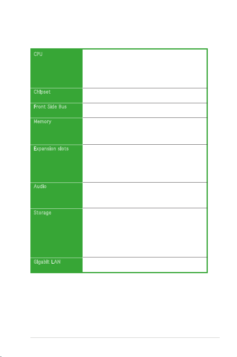
P5N-E SLI specications summary
(continued on the next page)
CPU
Chips et
Front Side Bus
Memor y
Expan sion slots
Audio
Stora ge
Gigab it LAN
LGA775 socket for Intel® Quad-Core/ Core™ Extreme/
Pentium D/ Pentium® 4/ Celeron® CPU processors
Compatible with Intel® 06/05B/05A processors
Supports Intel® Enhanced Memory 64 Technology (EM64T)
Supports Enhanced Intel SpeedStep® Technology (EIST)
Supports Intel® Hyper-Threading Technology
North Bridge: NVIDIA nForce® 650i SLI™ (C55)
South Bridge: NVIDIA nForce® 430i (MCP 51)
1333**/1066/800/533 MHz (** available when CPUs
are ready for 1333MHz FSB)
Dual-channel memory architecture
4 x 240-pin DIMM sockets support unbufferred non-ECC
DDR2-800/667/533 memory modules
Supports up to 8 GB system memory
2 x PCI Express x16 slots with Scalable Link Interface
(SLI™) support
- Single VGA mode: x16 (Default)
- SLI mode: x8, x8
1 x PCI Express x1 slot
2 x PCI slots (PCI 2.2)
Realtek ALC883 6-channel CODEC
1 x Coaxial S/PDIF out port
Supports Audio Sensing and Enumeration Technology
Supports Multi-Streaming Technology
NVIDIA nForce® 430i supports:
- 2 x Ultra DMA 133/100/66/33
- 4 x Serial ATA 3Gb/s devices
- RAID 0, RAID 1, RAID 0+1, RAID 5 and JBOD
conguration
Jmicron JMB 360 SATA controller supports:
- 1 x External Serial ATA 3Gb/s device (SATA On the-Go)
Marvell 88E1116 PHY Gigabit LAN controller
Supports AI NET2 network diagnosis before entering OS
xii
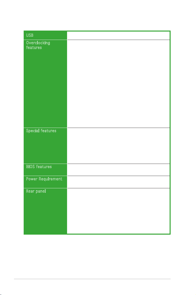
Supports up to 8 USB 2.0 ports
Intelligent overclocking tool:
- AI Overclocking (Intelligent CPU Frequency
Tuner)
ASUS CPU Lock Free
Precision Tweaker supports:
- vDIMM voltage: 8-step DRAM voltage control
- vCore voltage: Adjustable CPU voltage at 6.25mv
- vChip voltage: 4-step Chip voltage control
Stepless Frequency Selection (SFS):
- FSB tuning from 200MHz to 750 MHz at 1MHz
increment;
- memory tuning from 533MHz to 1200MHz at
1MHz increment;
- PCI-E tuning from 100MHz to 131MHz at 1 MHz
increment
ASUS CPU Multiplier
Overclocking Protection:
- ASUS C.P.R. (CPU Parameter Recall)
ASUS Q-Fan2
ASUS Q-Connector
ASUS Fanless Design
ASUS MyLogo2
ASUS O.C. Prole
ASUS PC Probe2
ASUS Update
4 MB Flash ROM, Award BIOS, PnP, DMI2.0, SM BIOS 2.3,
WfM2.0, ASUS EZ Flash 2, ASUS CrashFree BIOS2
ATX power supply (with 24-pin and 4-pin 12V plugs)
ATX 12V 2.0 compliant
1 x Parallel port
1 x 1394a connector
1 x LAN (RJ-45) ports
4 x USB 2.0/1.1 ports
1 x Coaxial S/PDIF Out port
1 x External SATA
1 x PS/2 keyboard port (purple)
1 x PS/2 mouse port (green)
6-channel audio I/O ports
(continued on the next page)
USB
Overc locking
featu res
Speci al features
BIOS features
Power Requirement
Rear panel
P5N-E SLI specications summary
xiii
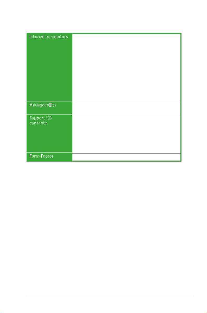
Inter nal connectors
Manag eability
Suppo rt CD
conte nts
Form Factor
1 x Floppy disk drive connector
1 x 1394a connector
1 x CD audio in connector
1 x 24-pin ATX power connector
1 x 4-pin ATX 12 V power connector
2 x USB connectors for additional four USB 2.0 ports
1 x S/PDIF out connector
1 x COM Port connector
1 x Chassis intrusion connector
1 x Front panel connector (AAFP)
1 x CPU Fan connector
2 x Chassis fan connectors
System panel connector
WfM 2.0, DMI 2.0,WOR by Ring, WOL by PME, WOR by
PME, WO USB/KB/MS, PXE, RPL&AI Net2
Device drivers
ASUS PC Probe II
ASUS Update
NV RIS (Remote Installation Service)
Microsoft® DirectX 9.0c
Anti-Virus Utility (OEM version)
Adobe Acrobat Reader v7.0
ATX form factor: 12 in x 9 in (30.5 cm x 22.9 cm)
* Specications are subject to change without notice.
P5N-E SLI specications summary

xiv

1
Product
introduction
This chapter describes the motherboard
features and the new technologies
it supports.
1-2 Chapter 1: Product introduction
1.1 Welcome!
Thank you for buying an ASUS® P5N-E SLI motherboard!
The motherboard delivers a host of new features and latest technologies,
making it another standout in the long line of ASUS quality motherboards!
Before you start installing the motherboard, and hardware devices on it,
check the items in your package with the list below.
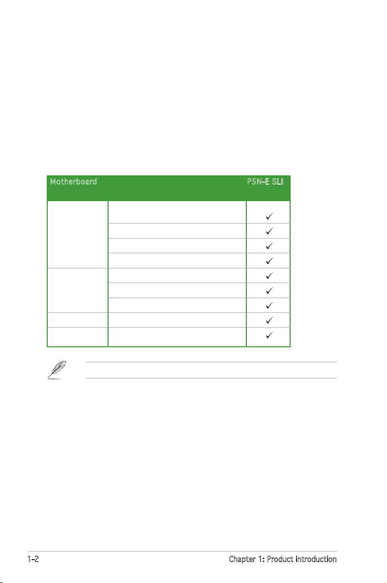
1.2 Package contents
Check your motherboard package for the following items.
If any of the above items is damaged or missing, contact your retailer.
Mothe rboard P5N-E SLI
Cables Serial ATA and power cablesSerial ATA and power cables
1 x Ultra DMA 133/100/66 cable
1 x USB cable 2port
1 x Floppy disk drive cable
Accessories I/O shield
2-in-1 ASUS Q-Connector kit
1 x SLI soft bridge
Application CD ASUS motherboard support CD
Documentation User guide
ASUS P5N-E SLI 1-3
1.3 Special features
1.3. 1 Produ c t hi g hli g h ts
LGA775 I n t e lIntel® Quad-co r e P r o c essor Re a d y
This motherboard supports the latest powerful and energy efcient
processors from Intel. Intel® Quad-core is based on the Intel Core
Microarchitecture process technology that allows users to step up to new
levels of gaming experience and multi-tasking performance.
Combined with 1066/800 of front side bus (FSB), this motherboard
guarantees enhanced user experience in the digital home and ofce.
NVIDIA n F o r c e® 650i SL I ™
The NVIDIA® nForce® 650i SLI™ chipset supports the NVIDIA® Scalable
Link Interface (SLI™) technology that allows two graphics processing units
(GPUs) in a single system. It is a highly integrated, high-performance,
cost-effective processor.
Intel® Dual-Co r e T e c h nology C P U s u p p o rt
The motherboard supports dual-core processors containing two physical
CPU cores with dedicated L2 caches to meet demands for more powerful
processing.
Intel® EM64T
The motherboard supports Intel® processors with the Intel® EM64T
(Extended Memory 64 Technology). The Intel® EM64T feature allows your
computer to run on 64-bit operating systems and access larger amounts of
system memory for faster and more efcient computing.
Enhanced I n t e l SpeedSte p® Technol o g y ( E I ST)
The Enhanced Intel SpeedStep® Technology (EIST) intelligently manages
the CPU resources by automatically adjusting the CPU voltage and core
frequency depending on the CPU loading and system speed or power
requirement.
1-4 Chapter 1: Product introduction
DDR2 mem o r y s u p port
The motherboard supports DDR2 memory which features data transfer rates of
800 MHz, 667 MHz or 533 MHz to meet the higher bandwidth requirements
of the latest 3D graphics, multimedia, and Internet applications. The
dual-channel DDR2 architecture doubles the bandwidth of your system
memory to boost system performance, eliminating bottlenecks with peak
bandwidths of up to 10.7 GB/s. See pages 1-17 to 1-21 for details.
PCI Expr e s s ™ i n terface
The motherboard fully supports PCI Express, the latest I/O interconnect
technology that speeds up the PCI bus. PCI Express features point-to-point
serial interconnections between devices and allows higher clockspeeds by
carrying data in packets. This high speed interface is software compatible
with existing PCI specications. See pages 1-24 and 1-25 for details.
Gigabit L A N
The Marvell Gigabit LAN controller delivers transfer speeds up to ten times
faster than conventional 10/100 Ethernet connections. Gigabit LAN is
the networking standard for the early future and is ideal for handling large
amounts of data such as video, audio, and voice.
Serial ATA 3.0 Gb/s technology and SATA on the go
This motherboard supports the next-generation hard drives based on
the Serial ATA (SATA) 3Gb/s storage specication, delivering enhanced
scalability and doubling the bus bandwidth for high-speed data retrieval
and saves. The external SATA port located at the back I/O provides smart
setup and hot-plug functions. Easily backup photos, videos and other
entertainment contents on external devices. See pages 1-31 and 2-19 for
details.
High Def i n i t i o n Audio
The onboard 6-channel High Denition audio CODEC enables high-quality
Realtek ALC883 audio CODEC, which automatically detects and identies
what types of peripherals are plugged into the audio I/O jacks and noties
users of inappropriate connection. See page 1-28 for details.
S/PDIF d i g i t a l sound re a d y
The motherboard supports the S/PDIF technology through the S/PDIF
interfaces on the rear panel and at midboard. The S/PDIF technology
turns your computer into a high-end entertainment system with digital
connectivity to powerful audio and speaker systems. See page 1-28.
ASUS P5N-E SLI 1-5
1.3. 2 Innov a tive ASU S fea t u res
ASUS O.C . P r o f i le
The motherboard features the ASUS O.C. Prole that allows users to
conveniently store or load multiple BIOS settings. The BIOS settings can be
stored in the CMOS or a separate le, giving users freedom to share and
distribute their favorite settings. See pages 2-45 and 2-46 for details.
CrashFre e B I O S 2
This feature allows you to restore the original BIOS data from the support
CD in case when the BIOS codes and data are corrupted. This protection
eliminates the need to buy a replacement ROM chip. See page 2-6 for
details.
ASUS EZ F l a s h 2
EZ Flash 2 is a user-friendly BIOS update utility. Simply press the predened
hotkey to launch the utility and update the BIOS without entering the OS.
Update your BIOS easily without preparing a bootable diskette or using an
OS-based ash utility. See pages 2-8 and 2-47 for details.
C.P.R. ( C P U P a r ameter R e c a l l )
The C.P.R. feature of the motherboard BIOS allows automatic re-setting to
the BIOS default settings in case the system hangs due to overclocking.
When the system hangs due to overclocking, C.P.R. eliminates the need
to open the system chassis and clear the RTC data. Simply shut down and
reboot the system, and the BIOS automatically restores the CPU default
setting for each parameter.
ASUS Q-C o n n e c t o r
ASUS Q-Connector allows you to easily connect or disconnect the chassis
front panel cables to the motherboard. This unique module eliminates the
trouble of connecting the system panel cables one at a time and avoiding
wrong cable connections. See page 1-37 for details.
1-6 Chapter 1: Product introduction
Fanless D e s i g n
Cooling fans, though a popular thermal solution, also come with noise and
malfunction likelyhood. ASUS Motherboard’s fansless concept is specically
created to provide a cool environment without all the baggage.
ASUS has devoted special efforts to address the thermal issues across the
motherboard, and most notably the areas that reside the CPU, power, VGA,
Northbridge and Southbridge. The heat sinks and strategic board layout
were tailor made to dissipate heat in the most efcient manner.
AI NET 2
AI NET 2 is a BIOS-based diagnostic tool that detects and reports Ethernet
cable faults and shorts. With this utility, you can easily monitor the
condition of the Ethernet cable(s) connected to the Marvell LAN (RJ-45)
port. During the bootup process, AI NET 2 immediately diagnoses the LAN
cable and reports shorts and faults up to 100 meters at 1 meter accuracy.
See page 2-25 for details.
Precisio n T w e a k er
This feature allows you to ne tune the CPU/memory voltage and gradually
increase the memory Front Side Bus (FSB) and PCI Express frequency at
1MHz increment to achieve maximum system performance.
ASUS MyL o g o 2 ™
This new feature present in the motherboard allows you to personalize and
add style to your system with customizable boot logos. See page 2-42 for
details.
ASUS P5N-E SLI 1-7
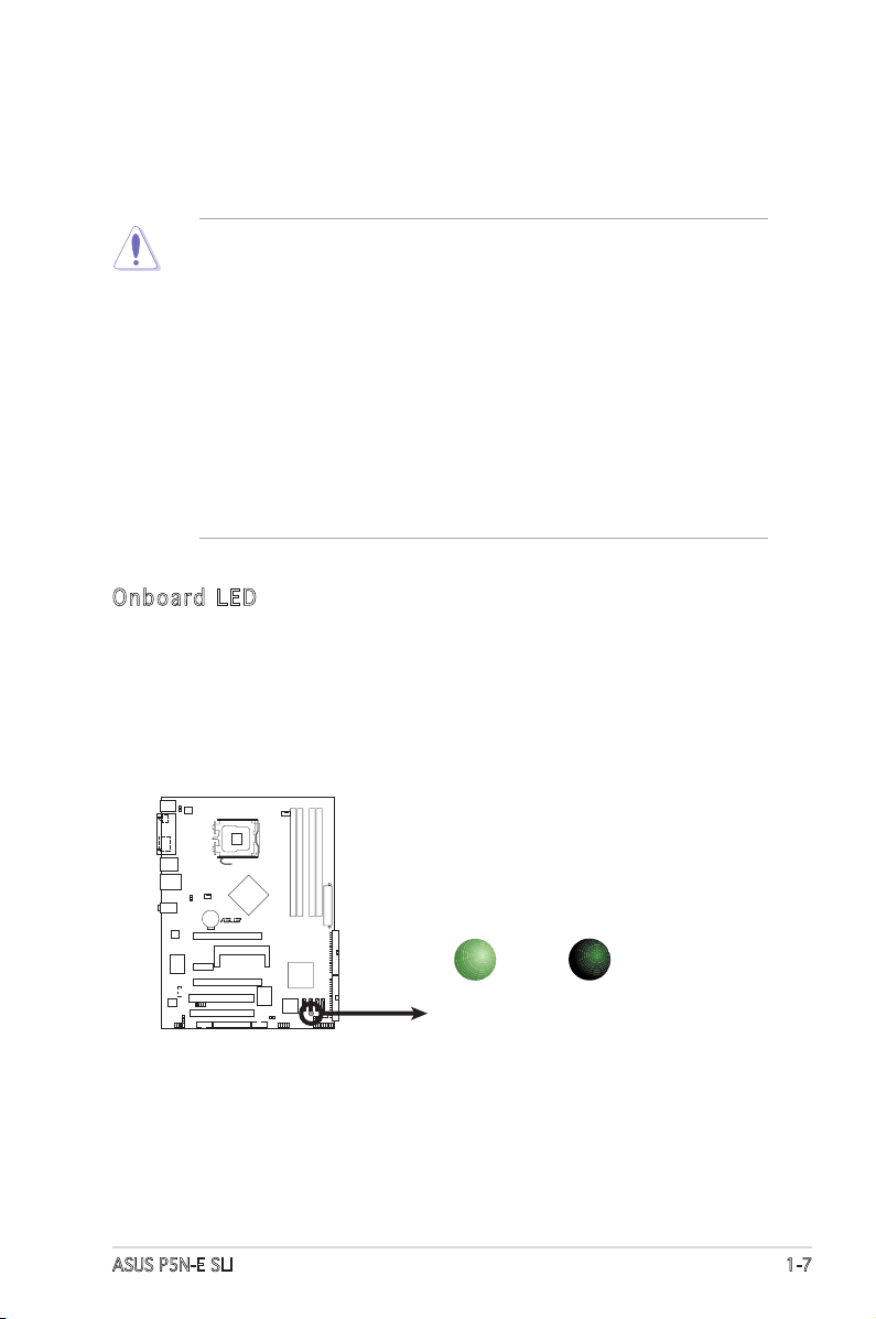
Onboard L E D
The motherboard comes with a standby power LED. The green LED
lights up to indicate that the system is ON, in sleep mode, or in softoff mode. This is a reminder that you should shut down the system
and unplug the power cable before removing or plugging in any
motherboard component. The illustration below shows the location of
the onboard LED.
1.4 Before you proceed
Take note of the following precautions before you install motherboard
components or change any motherboard settings.
• Unplug the power cord from the wall socket before touching any
component.
• Use a grounded wrist strap or touch a safely grounded object or to
a metal object, such as the power supply case, before handling
components to avoid damaging them due to static electricity.
• Hold components by the edges to avoid touching the ICs on them.
• Whenever you uninstall any component, place it on a grounded
antistatic pad or in the bag that came with the component.
• Before you install or remove any component, ensure
that the ATX power supply is switched off or the power cord is
detached from the power supply. Failure to do so may cause severe
damage to the motherboard, peripherals, and/or components.
P5N-E SLI
R
P5N-E SLI Onboard LED
SB_PWR
ON
Standby
Power
OFF
Powered
Off
1-8 Chapter 1: Product introduction
1.5 Motherboard overview
Before you install the motherboard, study the conguration of your chassis
to ensure that the motherboard ts into it.
Make sure to unplug the power cord before installing or removing the
motherboard. Failure to do so can cause you physical injury and damage
motherboard components.
Do not overtighten the screws! Doing so can damage the motherboard.
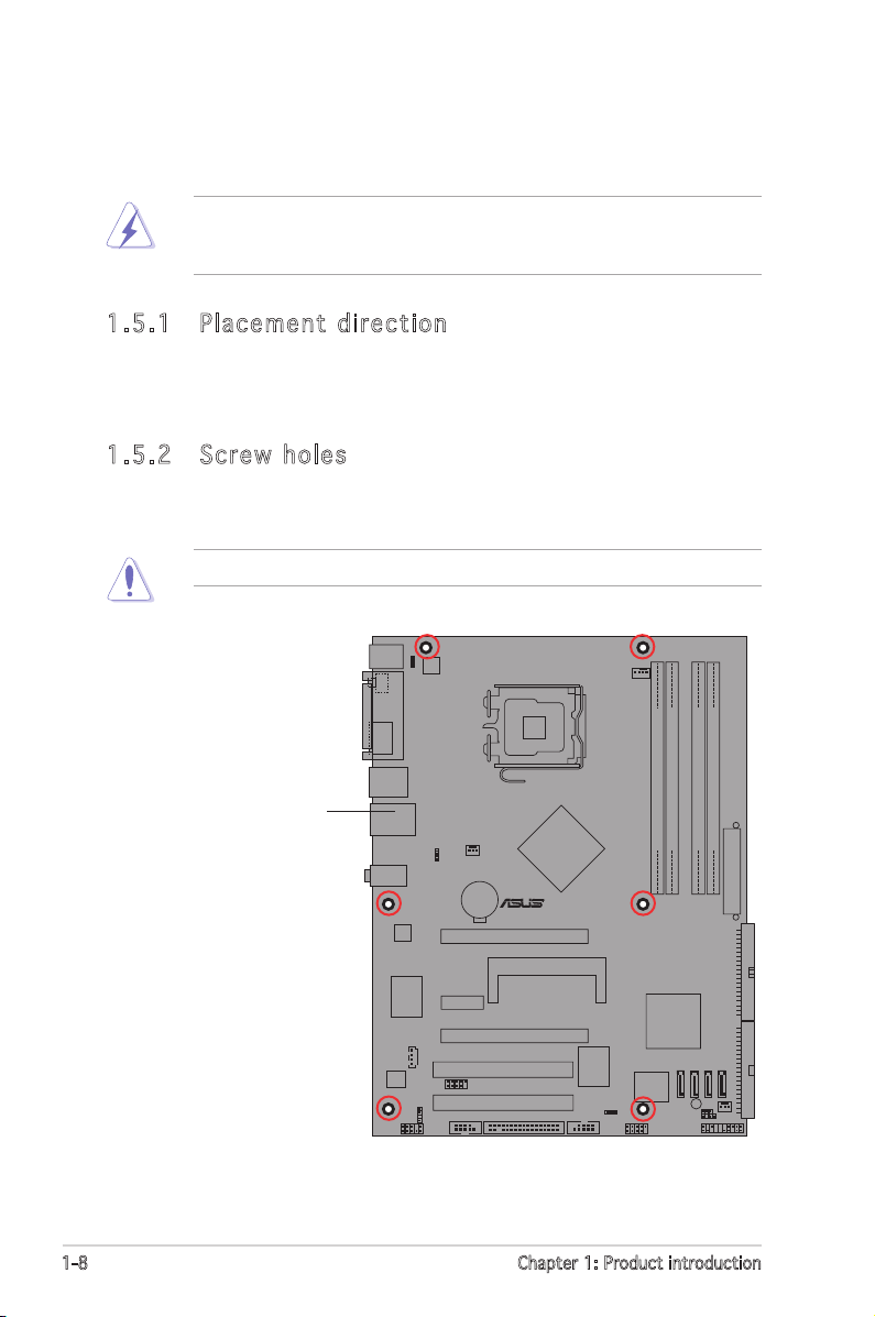
1.5. 1 Place m ent d ire c t ion
When installing the motherboard, make sure that you place it into the
chassis in the correct orientation. The edge with external ports goes to the
rear part of the chassis as indicated in the image below.
1.5. 2 Screw hol e s
Place six (6) screws into the holes indicated by circles to secure the
motherboard to the chassis.
P5N-E SLI
R
Place this side towards
the rear of the chassis
ASUS P5N-E SLI 1-9
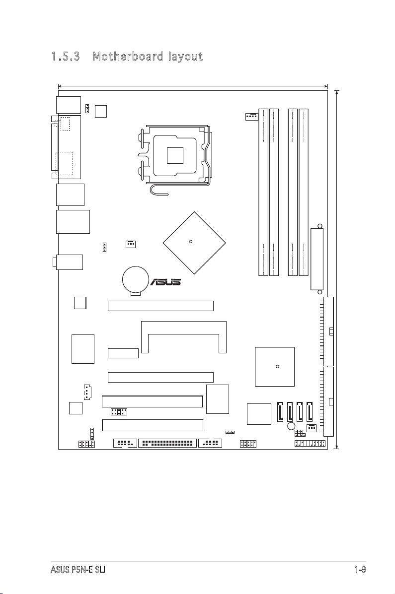
1.5. 3 Mothe r boar d la y o ut
NVIDIA
nForce 650i SLI
PCIEX16_1
PCIEX1_2
PCIEX16_2
PCI1
PCI2
SEC_IDE
PRI_IDE
CD
P5N-E SLI
SLI_CON
SATA1
SATA2
SATA3
SATA4
SB_PWR
CHASSIS
PS/2KBMS
T:Mouse
B:Keyboard
SPDIF_O1
ESATA
USB12
LAN_USB34
22.9cm (9.0in)
30.5cm (12in)
R
NVIDIA
nForce 430i
R
LGA775
CR2032 3V
Lithium Cell
CMOS Power
DDR2 DIMM_A1 (
64
bit,240-pin module)
DDR2 DIMM_A
2
(
64
bit,240-pin module)
DDR2 DIMM_
B
1 (
64
bit,240-pin module)
DDR2 DIMM_
B2
(
64
bit,240-pin module)
EATXPWR
FLOPPY
PANEL
USB56
USB78
CLRTC
CHA_FAN2
AAFP
SPDIF_OUT
CHA_FAN1
KBPWR
CPU_FAN
PARALLEL
PORT
Super I/O
IE1394_2COM1
ALC883
Marvell
88E1116
USBPW1-4
ATX12V
VIA
VT6308P
4Mb
BIOS
AUDIO
USBPW5-8
TM
1-10 Chapter 1: Product introduction
1.6 Central Processing Unit (CPU)
The motherboard comes with a surface mount LGA775 designed for the
Intel® Quad-Core, Core™2 Extreme, Core™2 Duo, Pentium® Extreme,
Pentium® D, Pentium® 4 and Celeron® D processors in the 775-land
package.
•
Install a chassis fan with at least a speed of 2400 rpm and 8 CFM
turnrate when using a dual-core CPU to ensure system stability.
Overheating can permanently damage the system and/or CPU.
• Upon purchase of the motherboard, make sure that the PnP cap is
on the socket and the socket contacts are not bent. Contact your
retailer immediately if the PnP cap is missing, or if you see any
damage to the PnP cap/socket contacts/motherboard components.
ASUS will shoulder the cost of repair only if the damage is shipment/
transit-related.
•
Keep the cap after installing the motherboard. ASUS will process
Return Merchandise Authorization (RMA) requests only if the
motherboard comes with the cap on the LGA775 socket.
• The product warranty does not cover damage to the socket contacts
resulting from incorrect CPU installation/removal, or misplacement/
loss/incorrect removal of the PnP cap.
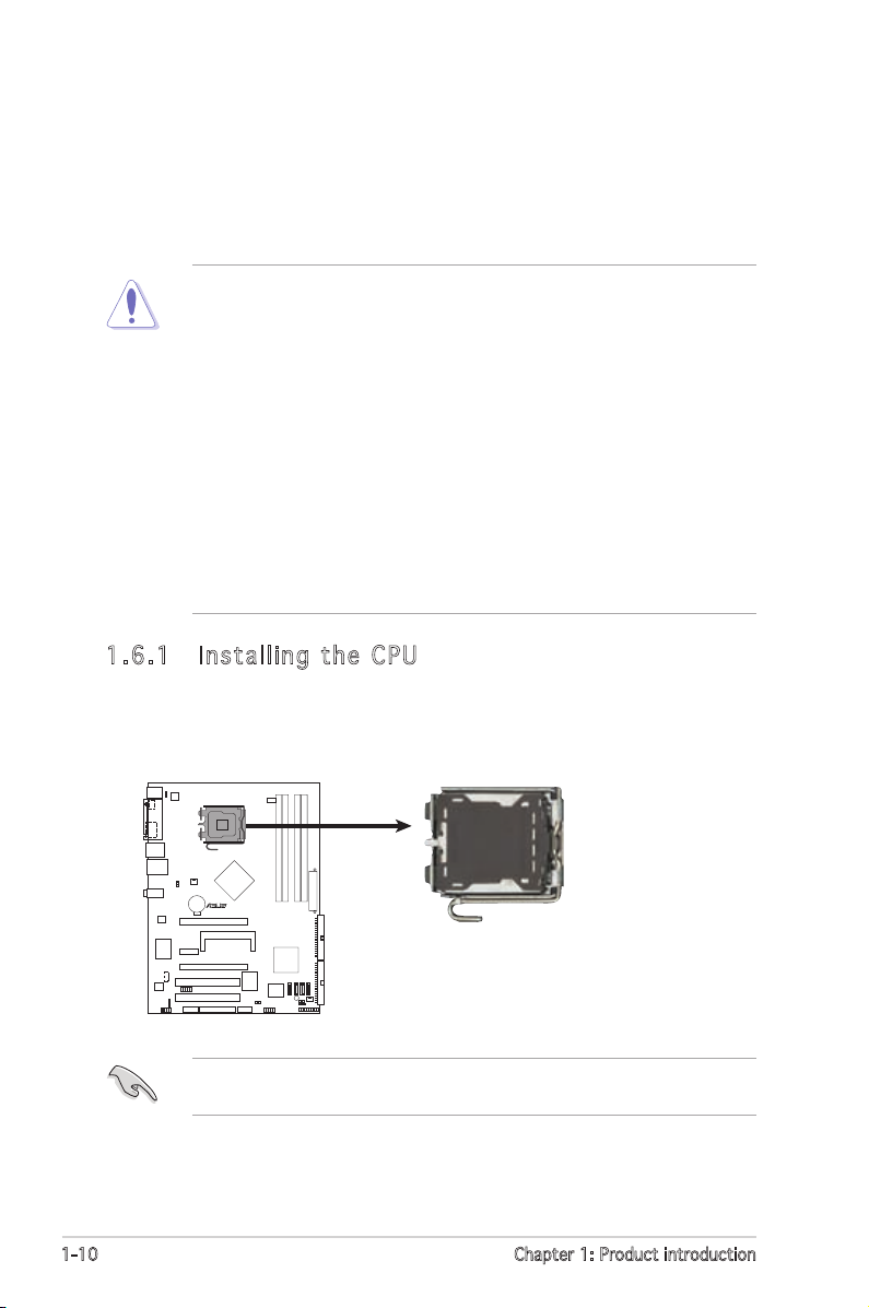
1.6. 1 Insta l ling the C PU
To install a CPU:
1. Locate the CPU socket on the motherboard.
Before installing the CPU, make sure that the cam box is facing towards
you and the load lever is on your left.
P5N-E SLI
R
P5N-E SLI
CPU Socket 775
ASUS P5N-E SLI 1-11
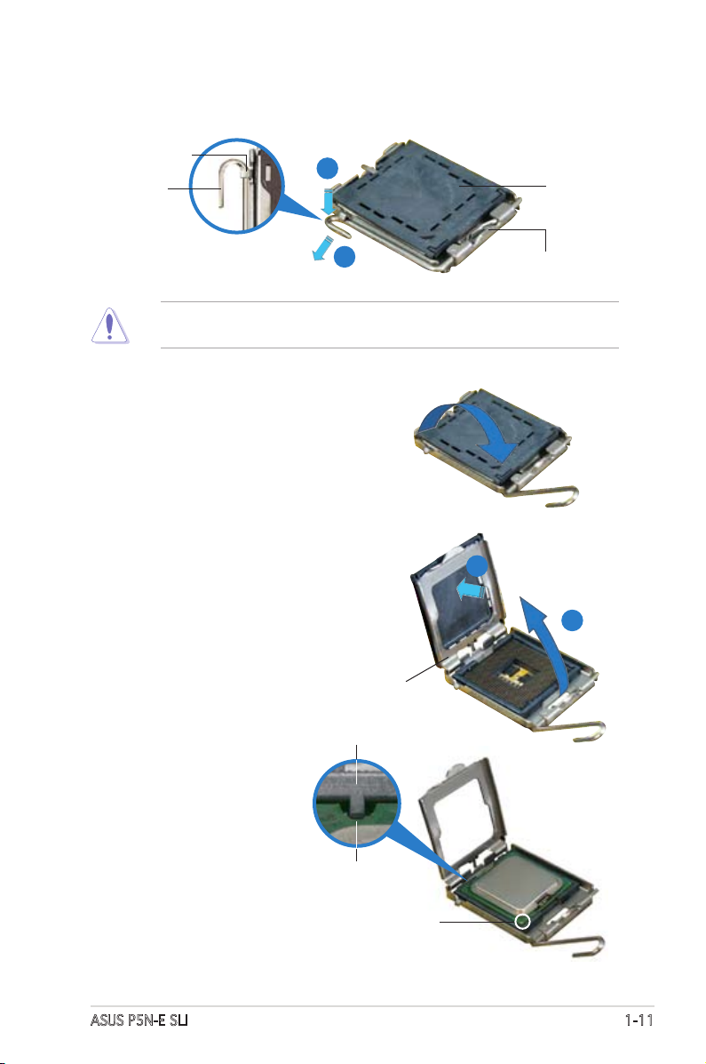
2. Press the load lever with your thumb (A), then move it to the left (B)
until it is released from the retention tab.
Retention tab
Load lever
This side of the socket
box should face you.
PnP cap
A
B
To prevent damage to the socket pins, do not remove the PnP cap
unless you are installing a CPU.
3. Lift the load lever in the direction
of the arrow to a 135º angle.
4. Lift the load plate with your
thumb and forenger to a 100º
angle (A), then push the PnP cap
from the load plate window to
remove (B).
5. Position the CPU over
the socket, making sure
that the gold triangle
is on the bottom-left
corner of the socket.
The socket alignment
key should t into the
CPU notch.
CPU notch
Gold triangle mark
Load plate
A
B
Alignment key
1-12 Chapter 1: Product introduction
The CPU ts in only one correct orientation. DO NOT force the CPU
into the socket to prevent bending the connectors on the socket and
damaging the CPU!
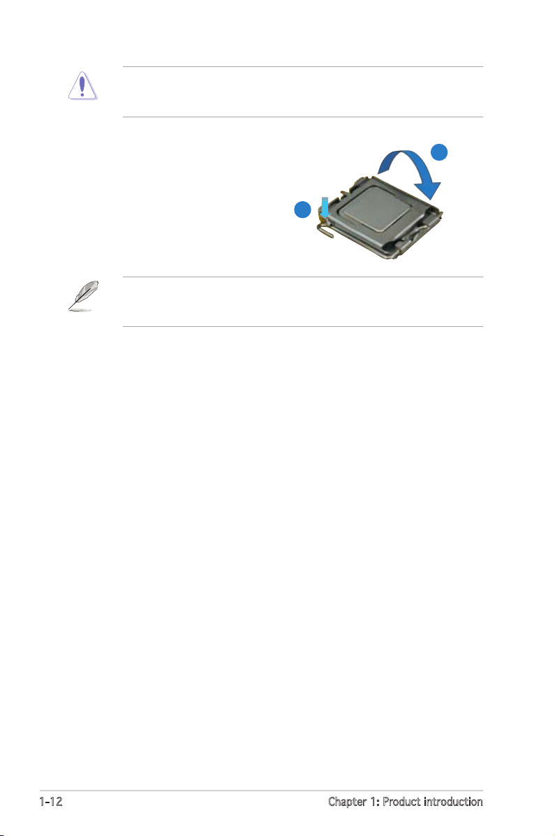
6. Close the load plate (A), then
push the load lever (B) until it
snaps into the retention tab.
A
B
The motherboard supports Intel® Pentium® 4 LGA775 processors with
the Intel® Enhanced Memory 64 Technology (EM64T), Enhanced Intel
SpeedStep® Technology (EIST), and Hyper-Threading Technology.
ASUS P5N-E SLI 1-13
Fastener
Motherboard hole
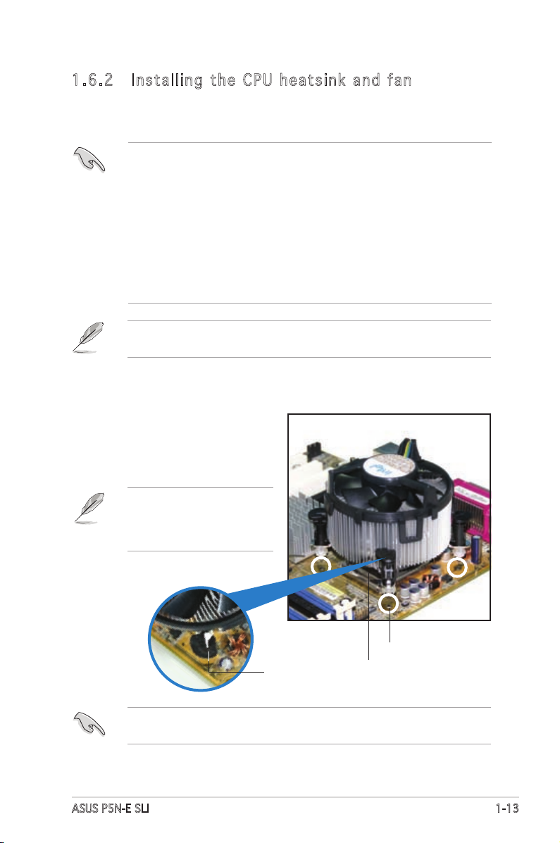
1.6. 2 Insta l ling the C PU h e ats i nk a n d fa n
Intel® LGA775 processors require a specially designed heatsink and fan
assembly to ensure optimum thermal condition and performance.
To install the CPU heatsink and fan:
1. Place the heatsink on top of the
installed CPU, making sure that
the four fasteners match the
holes on the motherboard.
Narrow end
of the groove
•
When you buy a boxed Intel® processor, the package includes the
CPU fan and heatsink assembly. If you buy a CPU separately, make
sure that you use only Intel®-certied multi-directional heatsink and
fan.
•
Your Intel® LGA775 processor heatsink and fan assembly comes in a
push-pin design and requires no tool to install.
•
If you purchased a separate CPU heatsink and fan assembly, make
sure that you have properly applied Thermal Interface Material to
the CPU heatsink or CPU before you install the heatsink and fan
assembly.
Make sure that you have installed the motherboard to the chassis before
you install the CPU fan and heatsink assembly.
Make sure to orient each fastener with the narrow end of the groove
pointing outward. (The photo shows the groove shaded for emphasis.)
Orient the heatsink and fan
assembly such that the CPU
fan cable is closest to the
CPU fan connector.
1-14 Chapter 1: Product introduction
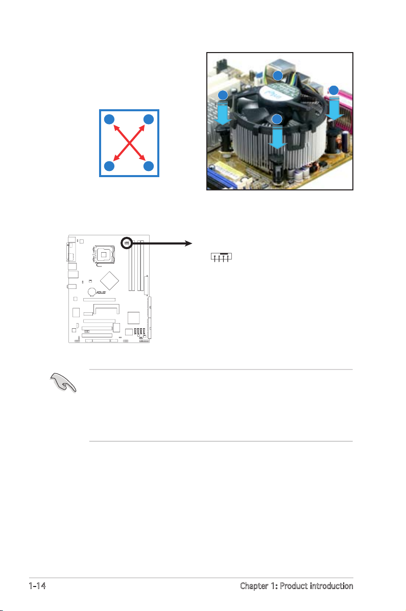
3. Connect the CPU fan cable to the connector on the motherboard
labeled CPU_FAN.
2. Push down two fasteners at
a time in a diagonal sequence
to secure the heatsink and fan
assembly in place.
B
B
A
A
A
A
B
B
• Do not forget to connect the CPU fan connector! Hardware
monitoring errors can occur if you fail to plug this connector.
• The retention module of some third-party CPU heatsink and fan
can interfere with chipset components at the bottom of the board.
Before purchasing a separate CPU heatsink and fan, make sure that
it will not interfere with the chipset components.
P5N-E SLI
R
P5N-E SLI
CPU Fan Connector
CPU_FAN
GND
CPU FAN PWR
CPU FAN IN
CPU FAN PWM
ASUS P5N-E SLI 1-15
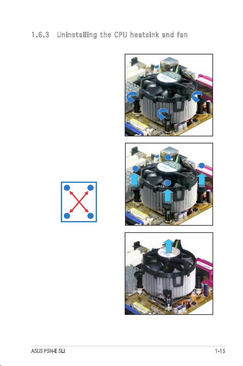
1.6. 3 Unins t alli n g t h e CP U hea t s ink and f an
To uninstall the CPU heatsink and fan:
1. Disconnect the CPU fan cable
from the connector on the
motherboard.
2. Rotate each fastener
counterclockwise.
3. Pull up two fasteners at a
time in a diagonal sequence to
disengage the heatsink and fan
assembly from the motherboard.
B
A
B
A
A
A
B
B
4. Carefully remove the heatsink
and fan assembly from the
motherboard.
1-16 Chapter 1: Product introduction
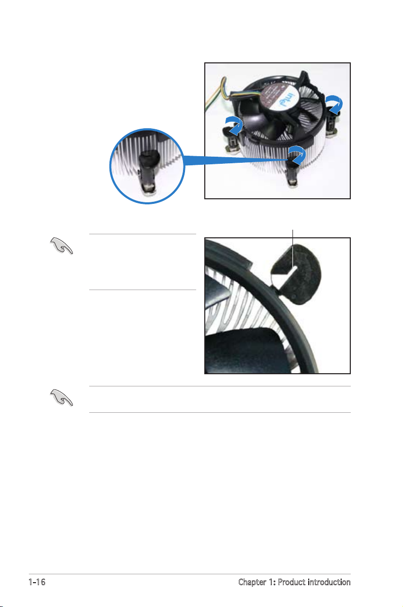
5. Rotate each fastener clockwise
to ensure correct orientation
when reinstalling.
The narrow end of the
groove should point outward
after resetting. (The photo
shows the groove shaded for
emphasis.)
Narrow end of the groove
Refer to the documentation in the boxed or stand-alone CPU fan package
for detailed information on CPU fan installation.
 Loading...