


Asus P5KPL, EPU, P5EPU User Manual
Rock Solid - Heart Touching
E4402
P5KPL/EPU
Motherboard
User Guide
ASUS contact information
ASUSTeK COMPUTER INC.
Address 15 Li-Te Road, Peitou, Taipei, Taiwan 11259
Telephone +886-2-2894-3447
Fax +886-2-2890-7798
E-mail info@asus.com.tw
Web site www.asus.com.tw
Technical Support
Telephone
Online support
+86-21-38429911
support.asus.com
ASUS COMPUTER INTERNATIONAL (America)
Address 800 Corporate Way, Fremont, CA 94539, USA
Telephone +1-510-739-3777
Fax +1-510-608-4555
Web site usa.asus.com
Technical Support
Telephone
Support fax
Online support
+1-812-282-2787
+1-812-284-0883
support.asus.com
ASUS COMPUTER GmbH (Germany and Austria)
Address
Fax
Web site
Online contact
Harkort Str. 21-23, D-40880 Ratingen, Germany
+49-2102-959911
www.asus.de
www.asus.de/saies
Technical Support
Component Telephone
System/Notebook/Eee/
LCD Telephone
Support Fax
Online support
+49-1805-010923
+49-1805-010920
+49-2102-9599-11
support.asus.com
P5№L/E^U
E4402
First Edition V1
March 2009
Copyright © 2009 ASUSTeK Computer, Inc. All Rights Reserved.
No part of this manual, including the products and software described in it, may be reproduced,
transmitted, transcribed, stored in a retrieval system, or translated into any language in any form or by any
means, except documentation kept by the purchaser for backup purposes, without the express written
permission of ASUSTeK Computer Inc. ("ASUS").
Product warranty or service will not be extended if: (1) the product is repaired, modified or altered, unless
such repair, modification of alteration is authorized in writing by ASUS; or (2) the serial number of the
product is defaced or missing.
ASUS PROVIDES THIS MANUAL "AS IS" WITHOUT WARRANTY OF ANY KIND, EITHER EXPRESS
OR IMPLIED, INCLUDING BUT NOT LIMITED TO THE IMPLIED WARRANTIES OR CONDITIONS OF
MERCHANTABILITY OR FITNESS FOR A PARTICULAR PURPOSE. IN NO EVENT SHALL ASUS, ITS
DIRECTORS, OFFICERS, EMPLOYEES OR AGENTS BE LIABLE FOR ANY INDIRECT, SPECIAL,
INCIDENTAL, OR CONSEQUENTIAL DAMAGES (INCLUDING DAMAGES FOR LOSS OF PROFITS,
LOSS OF BUSINESS, LOSS OF USE OR DATA, INTERRUPTION OF BUSINESS AND THE LIKE),
EVEN IF ASUS HAS BEEN ADVISED OF THE POSSIBILITY OF SUCH DAMAGES ARISING FROM ANY
DEFECT OR ERROR IN THIS MANUAL OR PRODUCT.
SPECIFICATIONS AND INFORMATION CONTAINED IN THIS MANUAL ARE FURNISHED FOR
INFORMATIONAL USE ONLY, AND ARE SUBJECT TO CHANGE AT ANY TIME WITHOUT NOTICE,
AND SHOULD NOT BE CONSTRUED AS A COMMITMENT BY ASUS. ASUS ASSUMES NO
RESPONSIBILITY OR LIABILITY FOR ANY ERRORS OR INACCURACIES THAT MAY APPEAR IN THIS
MANUAL, INCLUDING THE PRODUCTS AND SOFTWARE DESCRIBED IN IT.
Products and corporate names appearing in this manual may or may not be registered trademarks or
copyrights of their respective companies, and are used only for identification or explanation and to the
owners' benefit, without intent to infringe.
Contents
Notices vi
Safety information vii
About this guide vii
P5KPL/EPU specifications summary ix
Chapter 1: Product introduction
1.1 Welcome! 1-1
1.2 Package contents
1
-1
1.3 Special features 1-1
1.3.1 Product highlights 1-1
1.3.2 Innovative ASUS features
1
-2
1.4 Before you proceed
1
-4
1.5 Motherboard overview
1
-5
1.5.1 Placement direction 1-5
1.5.2 Screw holes 1-5
1.5.3 Motherboard layout 1-6
1.5.4 Layout contents
1
-6
1.6 Central Processing Unit (CPU) 1-7
1.6.1 Installing the CPU 1-7
1.6.2 Installing the CPU heatsink and fan 1-10
1.6.3 Uninstalling the CPU heatsink and fan 1-11
1.7 System memory 1-12
1.7.1 Overview 1-12
1.7.2 Memory configurations 1-13
1.7.3 Installing a DIMM 1-16
1.7.4 Removing a DIMM 1-16
1.8 Expansion slots 1-17
1.8.1 Installing an expansion card 1-17
1.8.2 Configuring an expansion card 1-17
1.8.3 PCI slots 1-17
1.8.4 PCI Express x1 slot 1-17
1.8.5 PCI Express x16 slot 1-17
1.9 Jumpers 1-18
Contents
1.10 Connectors 1-20
1.10.1 Rear panel connectors 1-20
1.10.2 Internal connectors 1-21
1.11 Software support 1-29
1.11.1 Installing an operating system 1-29
1.11.2 Support DVD information 1-29
Chapter 2: BIOS information
2.1 Managing and updating your BIOS 2-1
2.1.1 ASUS Update utility 2-1
2.1.2 ASUS EZ Flash 2 utility 2-2
2.1.3 ASUS CrashFree BIOS 3 utility 2-3
2.2 BIOS setup program 2-4
2.2.1 BIOS menu screen 2-5
2.2.2 Menu bar 2-5
2.2.3 Navigation keys 2-6
2.2.4 Menu items 2-6
2.2.5 Submenu items 2-6
2.2.6 Configuration fields 2-6
2.2.7 Pop-up window 2-6
2.2.8 Scrollbar 2-6
2.2.9 General help 2-6
2.3 Main menu 2-7
2.3.1 System Time 2-7
2.3.2 System Date 2-7
2.3.3 Primary IDE Master/SATA1-4 2-7
2.3.4 IDE Configuration 2-8
2.3.5 System Information 2-9
2.4 Advanced menu 2-9
2.4.1 JumperFree Configuration 2-9
2.4.2 USB Configuration 2-11
2.4.3 CPU Configuration 2-12
Contents
2.4.4 Chipset 2-13
2.4.5 Onboard Devices Configuration 2-13
2.4.6 PCIPnP 2-14
2.5 Power menu 2-15
2.5.1 Suspend Mode 2-15
2.5.2 ACPI 2.0 Support 2-15
2.5.3 ACPI APIC Support 2-15
2.5.4 АРМ Configuration 2-15
2.5.5 Hardware Monitor 2-16
2.6 Boot menu 2-17
2.6.1 Boot Device Priority 2-17
2.6.2 Boot Settings Configuration 2-17
2.6.3 Security 2-18
2.7 Tools menu 2-20
2.7.1 Al NET 2 2-20
2.7.2 ASUS EZ Flash 2 2-20
2.7.3 Express Gate 2-20
2.8 Exit menu 2-21
Notices
Federal Communications Commission Statement
This device complies with Part 15 of the FCC Rules. Operation is subject to the following two
conditions:
This device may not cause harmful interference, and
This device must accept any interference received including interference that may cause
undesired operation.
This equipment has been tested and found to comply with the limits for a Class В digital
device, pursuant to Part 15 of the FCC Rules. These limits are designed to provide
reasonable protection against harmful interference in a residential installation. This
equipment generates, uses and can radiate radio frequency energy and, if not installed
and used in accordance with manufacturer's instructions, may cause harmful interference
to radio communications. However, there is no guarantee that interference will not occur
in a particular installation. If this equipment does cause harmful interference to radio or
television reception, which can be determined by turning the equipment off and on, the user
is encouraged to try to correct the interference by one or more of the following measures:
Reorient or relocate the receiving antenna.
Increase the separation between the equipment and receiver.
Connect the equipment to an outlet on a circuit different from that to which the receiver is
connected.
Consult the dealer or an experienced radio/TV technician for help.
The use of shielded cables for connection of the monitor to the graphics card is required
to assure compliance with FCC regulations. Changes or modifications to this unit not
expressly approved by the party responsible for compliance could void the user's authority
to operate this equipment.
Canadian Department of Communications Statement
This digital apparatus does not exceed the Class В limits for radio noise emissions from
digital apparatus set out in the Radio Interference Regulations of the Canadian Department
of Communications.
This class В digital apparatus complies with Canadian ICES-003.
REACH
Complying with the REACH (Registration, Evaluation, Authorisation, and Restriction of
Chemicals) regulatory framework, we published the chemical substances in our products at
ASUS REACH website at http://green.asus.com/english/REACH.htm
DO NOT throw the motherboard in municipal waste. This product has been designed to
enable proper reuse of parts and recycling. This symbol of the crossed out wheeled bin
indicates that the product (electrical and electronic equipment) should not be placed in
municipal waste. Check local regulations for disposal of electronic products.
DO NOT throw the mercury-containing button cell battery in municipal waste. This symbol
of the crossed out wheeled bin indicates that the battery should not be placed in municipal
waste.
Safety information
Electrical safety
To prevent electrical shock hazard, disconnect the power cable from the electrical outlet
before relocating the system.
When adding or removing devices to or from the system, ensure that the power cables
for the devices are unplugged before the signal cables are connected. If possible,
disconnect all power cables from the existing system before you add a device.
Before connecting or removing signal cables from the motherboard, ensure that all
power cables are unplugged.
Seek professional assistance before using an adpater or extension cord. These devices
could interrupt the grounding circuit.
Make sure that your power supply is set to the correct voltage in your area. If you are
not sure about the voltage of the electrical outlet you are using, contact your local power
company.
If the power supply is broken, do not try to fix it by yourself. Contact a qualified service
technician or your retailer.
Operation safety
Before installing the motherboard and adding devices on it, carefully read all the manuals
that came with the package.
Before using the product, make sure all cables are correctly connected and the power
cables are not damaged. If you detect any damage, contact your dealer immediately.
To avoid short circuits, keep paper clips, screws, and staples away from connectors,
slots, sockets and circuitry.
Avoid dust, humidity, and temperature extremes. Do not place the product in any area
where it may become wet.
Place the product on a stable surface.
If you encounter technical problems with the product, contact a qualified service
technician or your retailer.
About this guide
This user guide contains the information you need when installing and configuring the
motherboard.
How this guide is organized
This guide contains the following parts:
Chapter 1: Product introduction
This chapter describes the features of the motherboard and the new technology it
supports.
Chapter 2: BIOS information
This chapter tells how to change system settings through the BIOS Setup menus.
Detailed descriptions of the BIOS parameters are also provided.
Where to find more information
Refer to the following sources for additional information and for product and software
updates.
1. ASUS websites
The ASUS website provides updated information on ASUS hardware and software
products. Refer to the ASUS contact information.
2. Optional documentation
Your product package may include optional documentation, such as warranty flyers,
that may have been added by your dealer. These documents are not part of the
standard package.
Conventions used in this guide
To make sure that you perform certain tasks properly, take note of the following symbols used
throughout this manual.
/
DANGER/WARNING: Information to prevent injury to yourself when trying to
complete a task.
fj1 CAUTION: Information to prevent damage to the components when trying to
' complete a task.
IMPORTANT: Instructions that you MUST follow to complete a task.
J^' NOTE: Tips and additional information to help you complete a task.
Typography
Bold text
Italics
<Key>
<Key 1 >+<Key2>+<Key3>
Indicates a menu or an item to select.
Used to emphasize a word or a phrase.
Keys enclosed in the less-than and greater-than sign means
that you must press the enclosed key.
Example: <Enter> means that you must press the Enter or
Return key.
If you must press two or more keys simultaneously, the key
names are linked with a plus sign (+).
Example: <Ctrl>+<Alt>+<D>
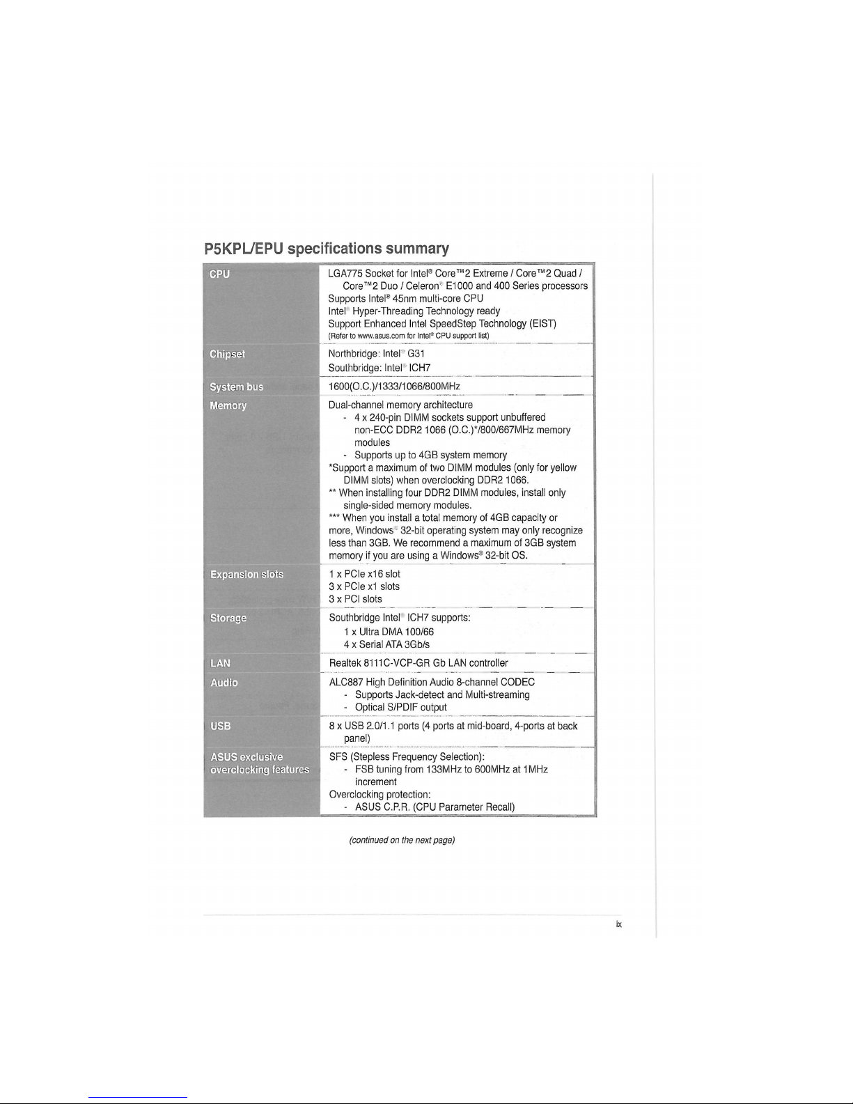
P5KPL/EPU specifications summary
CPU
LGA775 Socket for Intel® Core™2 Extreme / Core™2 Quad /
Core™2 Duo / Celeron" E1000 and 400 Series processors
Supports Intel® 45nm multi-core CPU
Intel Hyper-Threading Technology ready
Support Enhanced Intel SpeedStep Technology (EIST)
(Refer to www.asus.com for Intel® CPU support list)
Chipset
Northbridge: Intel G31
Southbridge: Intel ICH7
System bus
1600(0,C.)/1333/1066/800MHZ
Memory
Dual-channel memory architecture
- 4 x 240-pin DIMM sockets support unbuffered
non-ECC DDR2 1066 (0,C.)7800/667MHz memory
modules
- Supports up to 4GB system memory
'Support a maximum of two DIMM modules (only for yellow
DIMM slots) when overclocking DDR2 1066.
" When installing four DDR2 DIMM modules, install only
single-sided memory modules.
*** When you install a total memory of 4GB capacity or
more, Windows - 32-bit operating system may only recognize
less than 3GB. We recommend a maximum of 3GB system
memory if you are using a Windows® 32-bit OS.
Expansion slots
1 xPCIe x16 slot
3 x PCIe x1 slots
3 x PCI slots
Storage
Southbridge Intel ICH7 supports:
1 x Ultra DMA 100/66
4 x Serial ATA 3Gb/s
LAN
Realtek 8111C-VCP-GR Gb LAN controller
Audio
ALC887 High Definition Audio 8-channel CODEC
- Supports Jack-detect and Multi-streaming
- Optical S/PDIF output
USB
8 x USB 2.0/1.1 ports (4 ports at mid-board, 4-ports at back
panel)
ASUS exclusive
overclocking features
SFS (Stepless Frequency Selection):
- FSB tuning from 133MHz to 600MHz at 1 MHz
increment
Overclocking protection:
- ASUS C.P.R. (CPU Parameter Recall)
(continued on the next page)
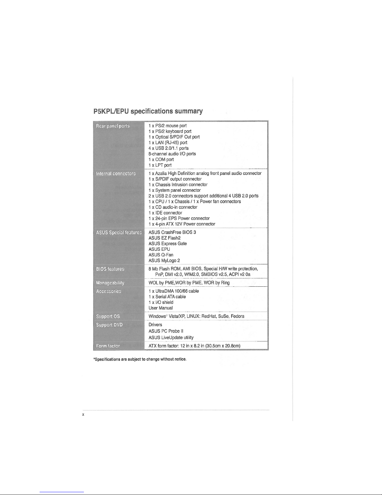
P5KPL/EPU specifications summary
Rear panel ports
1 x PS/2 mouse port
1 x PS/2 keyboard port
1 x Optical S/PDIF Out port
1 x LAN (RJ-45) port
4 x USB 2.0/1.1 ports
8-channel audio i/O poris
1 x COM port
1 x LPT port
Internal connectors
1 x Azalia High Definition analog front panel audio connector
1 x S/PDIF output connector
1 x Chassis Intrusion connector
1 x System panel connector
2 x USB 2.0 connectors support additional 4 USB 2.0 ports
1 x CPU /1 x Chassis /1 x Power fan connectors
1 x CD audio-in connector
1 x IDE connector
1 x 24-pin EPS Power connector
1 x 4-pin ATX I2V Power connector
ASUS Special features
ASUS CrashFree BIOS 3
ASUS EZ Flash2
ASUS Express Gate
ASUS EPU
ASUS Q-Fan
ASUS MyLogo 2
BIOS features
8 Mb Flash ROM, AMI BIOS, Special H/W write protection,
PnP, DMI v2.0, WfM2.0, SMBIOS v2.5, ACPI v2 0a
Manageability
WOL by PME.WOR by PME, WOR by Ring
1 x UltraDMA 100/66 cable 1 x UltraDMA 100/66 cable
1 x Serial ATA cable
1 x I/O shield
User Manual
Support OS
Windows1 Vista/XP, LINUX: RedHat, SuSe, Fedora
Support DVD
Drivers
ASUS PC Probe II
ASUS LiveUpdate utility
Form factor
ATX form factor: 12 in x 8.2 in (30.5cm x 20.8cm)
•Specifications are subject to change without notice.
Product introduction
1.1 Welcome!
Thank you for buying an ASUS" P5KPL/EPU motherboard!
The motherboard delivers a host of new features and latest technologies, making it another
standout in the long line of ASUS quality motherboards!
Before you start installing the motherboard, and hardware devices on it, check the items in
your package with the list below.
1.2 Package contents
Check your motherboard package for the following items.
Motherboard ASUS P5KPL/EPU motherboard
Cables 1 x Serial ATA cable
1 x Ultra DMA 100/66 cable
Accessories
1 x I/O shield
Application DVD ASUS motherboard support DVD
Documentation User Manual
If any of the above items is damaged or missing, contact your retailer.
1.3
1.3.1
Special features
Product highlights
PS§p]
|
CQlVg
Л
Intel® Core™2 Core™2 Quad / Core™2 Duo CPU support
This motherboard supports Intel' LGA775 Core™ 2 Core™ 2 Quad/
Core™ 2 Duo processors, which are excellent for multitasking,
multimedia, and enthusiastic gamers with 1600 (O.C.) /1333/1066/
800 MHz FSB. This motherboard also supports Intel* CPUs in the 45nm
manufacturing process.
Intel4 45nm Processor Ready
This motherboard supports the latest Intel 45nm CPU which introduces
new micro-architecture features for greater performance at a given
frequency, up to 50% larger L2 caches, and expanded power
management capabilities for new levels of energy efficiency.
ASUS P5KPL/EPU
1-1
Ш
ЩД Dual channel DDR2 1066 (0.с.)/800/667 support
Hffl This motherboard supports DDR2 memory that features data transfer
**—"" """" rates of 1066 (O.C.)/ 800/ 667 MHz providing great performance for 3D
graphics and other memory-demanding applications.
pQI PCI Express architecture
EXPRESS
pQ| Express is the latest I/O interconnect technology that replaces the
existing PCI. With a bus bandwidth two times higher than that of AGP 8X
interface, PCI Express x16 bus performs much better in applications such
as 3D gaming.
Serial ATA 3Gb/s technology
This motherboard supports hard drives based on the Serial ATA (SATA)
3Gb/s storage specifications, delivering enhanced scalability and
doubling the bus bandwidth for high-speed data saving and retrieval.
ismw
High Definition Audio
Enjoy high-quality sound system on your PC! The onboard 8-channel
HD audio (High Definition Audio, previously codenamed Azalia) CODEC
enables high-quality audio output, jack-detect feature automatically.
S/PDIF digital sound ready
This motherboard provides convenient connectivity to external home
theater audio systems via the S/PDIF-out (SONY-PHILIPS Digital
Interface) jack. It allows digital audio transfer and keeps the best signal
quality.
H
Gigabit LAN solution
The onboard LAN controller is a highly integrated Gb LAN controller. It is
enhanced with an ACPI management function to provide efficient power
management for advanced operating systems.
1.3.2 Innovative ASUS features
ASUS EPU
ASUS EPU detects the current computer loading and intelligently adjusts
the appropriate power usage in real-time.
ASUS MyLogo2™
This feature allows you to convert your favorite photo into a 256-color
boot logo for a more colorful and vivid image on your screen.
1-14 Chapter 1: Product introduction
ASUS CrashFree BIOS 3
ASUS CrashFree BIOS 3 is an auto-recovery tool that allows you to
restore a corrupted BIOS file using the bundled support DVD or USB disk
that contains the latest BIOS file.
ASUS EZ Flash 2
ASUS EZ Flash 2 is a utility that allows you to update the BIOS without
using an OS-based utility.
Express Gate
Express Gate is an ASUS exclusive OS that provides you with quick
access to the Internet and key applications before entering the Windows
-
OS.
• The actual boot time depends on the system configuration.
• ASUS Express Gate supports file uploading from SATA HDDs, ODDs and USB drives
and downloading to USB drives only.
C.P.R. (CPU Parameter Recall)
The BIOS C.P.R. feature automatically restores the CPU default settings
when the system hangs due to overclocking failure. C.P.R. eliminates the
need to open the system chassis and clear the RTC data. Simply shut
down and reboot the system, and the BIOS automatically restores the
CPU parameters to their default settings.
Green ASUS
This motherboard and its packaging comply with the European Union's
Restriction on the use of Hazardous Substances (RoHS). This is in line
with the ASUS vision of creating environment-friendly and recyclable
products/packaging to safeguard consumers' health while minimizing the
impact on the environment.
ASUS Al NET2
ASUS Al NET2 remotely detects the cable connection immediately after
turning on the system, and any faulty cable connections are reported
back up to 100 meters at 1 meter accuracy.
1.4 Before you proceed
Take note of the following precautions before you install motherboard components or change
any motherboard settings.
• Unplug the power cord from the wall socket before touching any component.
• Before handling components, use a grounded wrist strap or touch a safely grounded
object or a metal object, such as the power supply case, to avoid damaging them due to
static electricity.
• Hold components by the edges to avoid touching the ICs on them.
• Whenever you uninstall any component, place it on a grounded antistatic pad or in the
bag that came with the component.
• Before you install or remove any component, ensure that the ATX power supply is
switched off or the power cord is detached from the power supply. Failure to do so may
cause severe damage to the motherboard, peripherals, or components.
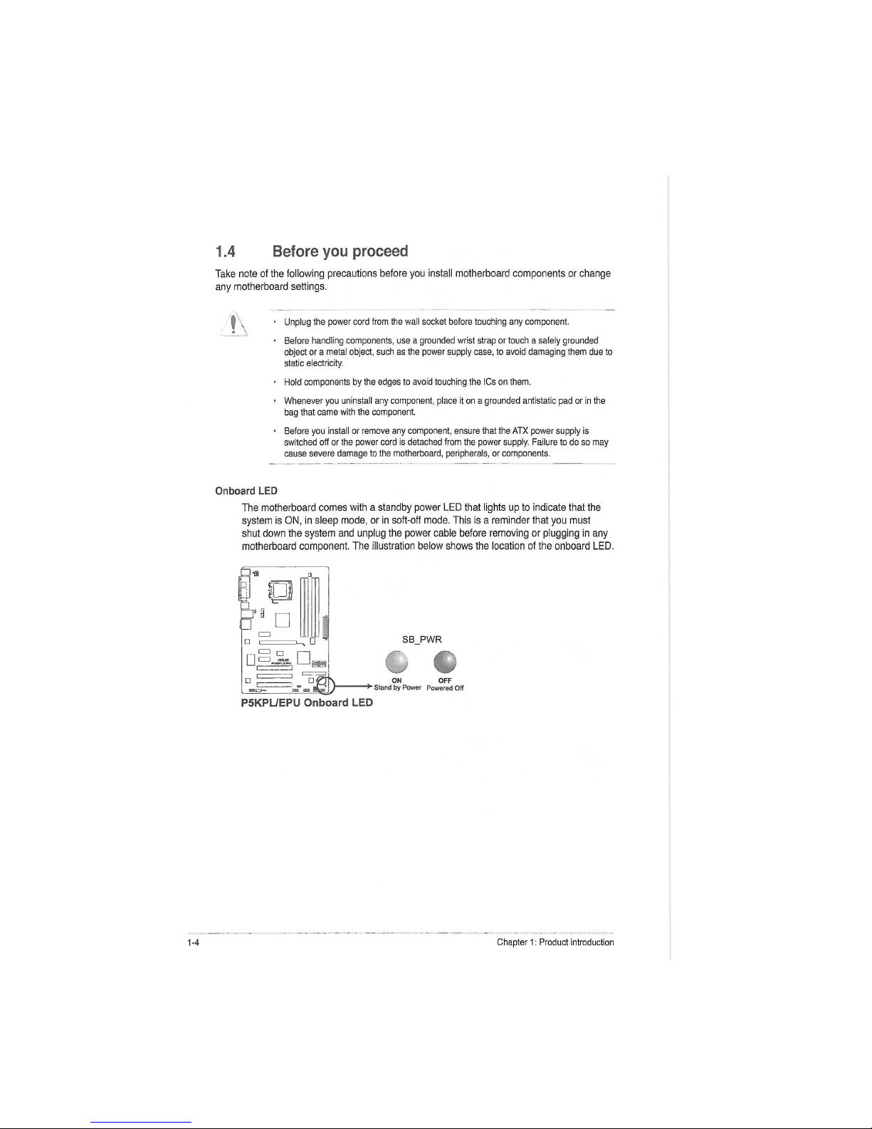
Onboard LED
The motherboard comes with a standby power LED that lights up to indicate that the
system is ON, in sleep mode, or in soft-off mode. This is a reminder that you must
shut down the system and unplug the power cable before removing or plugging in any
motherboard component. The illustration below shows the location of the onboard LED.
ON
Stand by Power
о G
SB PWR
OFF
Powered Off
P5KPL/EPU Onboard LED
1-16 Chapter 1: Product introduction
1.5 Motherboard overview
Before you install the motherboard, study the configuration of your chassis to ensure that the
motherboard fits into it.
Ensure that you unplug the power cord before installing or removing the motherboard.
Failure to do so can cause you physical injury and damage motherboard components.
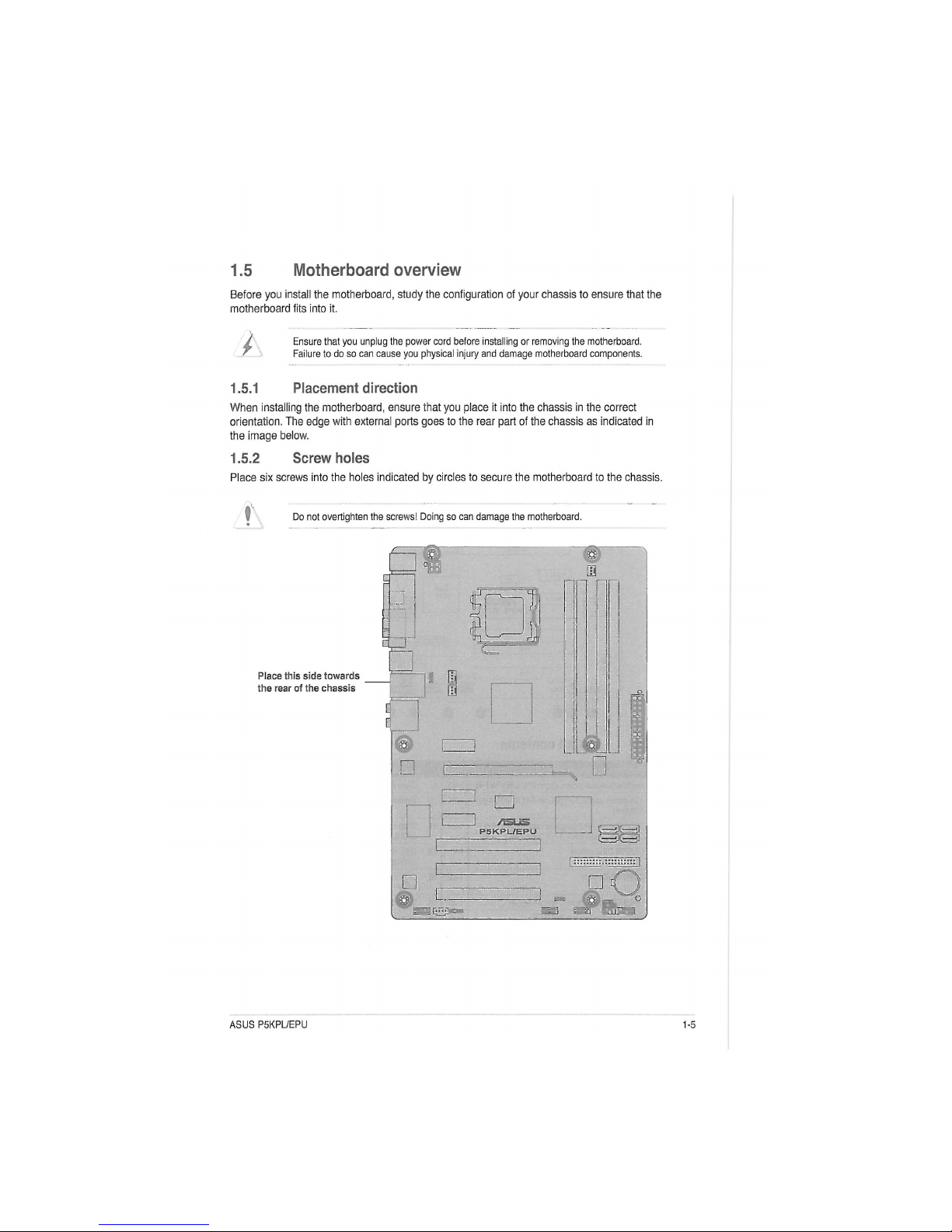
1.5.1 Placement direction
When installing the motherboard, ensure that you place it into the chassis in the correct
orientation. The edge with external ports goes to the rear part of the chassis as indicated in
the image below.
1.5.2 Screw holes
Place six screws into the holes indicated by circles to secure the motherboard to the chassis.
:
Do not overtighten the screws! Doing so can damage the motherboard.
Place this side towards
the rear of the chassis
•
•
•
J /SLS
P5KPL/EPU
ms-®
1
Ш
ASUS P5KPL/EPU
1-5
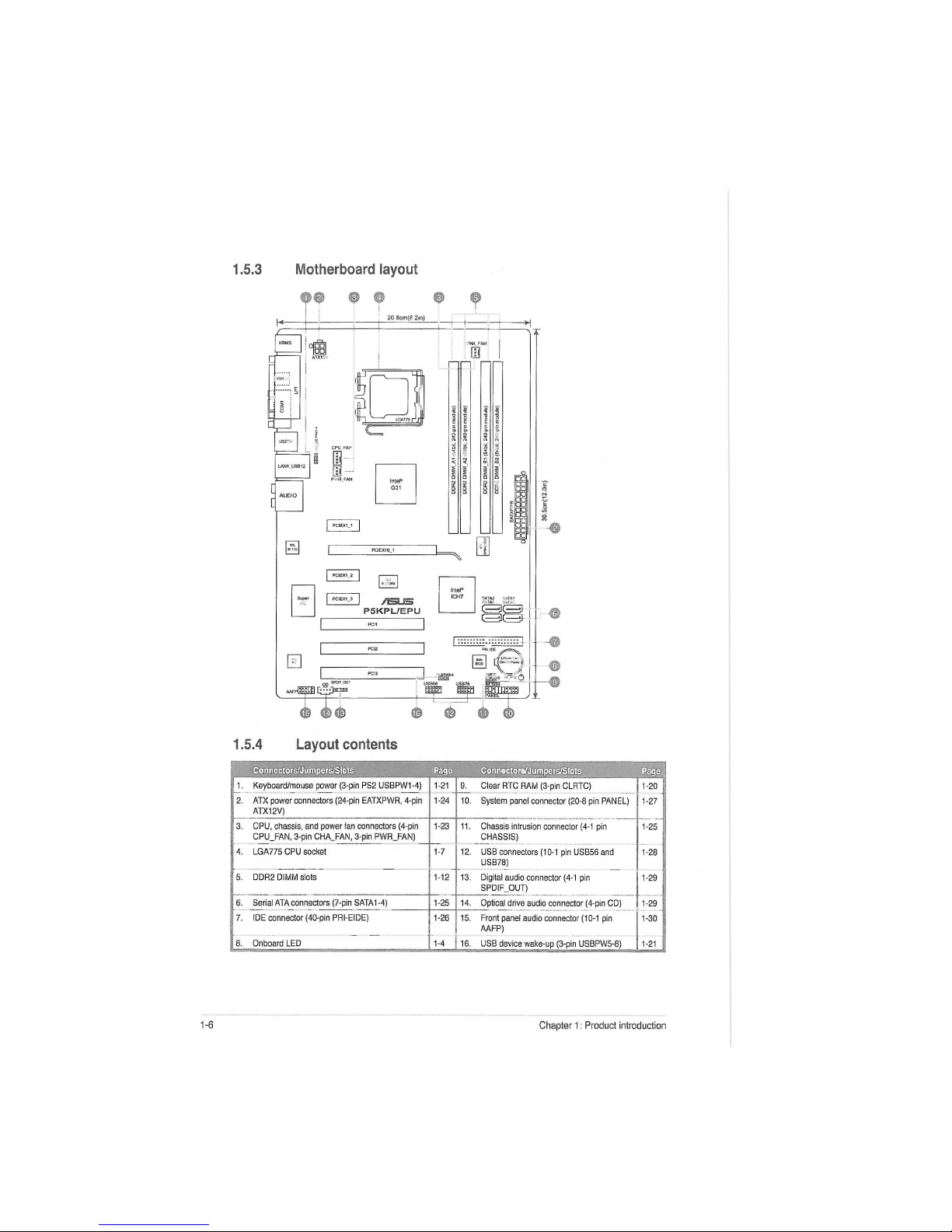
1.5.3 Motherboard layout
<ff> © 0 © ©
1.5.4 Layout contents
Connectors/Jumpers/Slots Page
Conn»ctpn/Jumpers/Slots Page
1. Keyboard/mouse power (3-pin PS2 USBPW1 -4) 1-21 9. Clear RTC RAM (3-pin CLRTC)
1-20
2. ATX power connectors (24-pin EATXPWR, 4-pin
ATX12V)
1-24 10. System panel connector (20-8 pin PANEL)
1-27
3. CPU, chassis, and power fan connectors (4-pin
CPU_FAN, 3-pin CHA_FAN, 3-pin PWR_FAN)
1-23 11. Chassis intrusion connector (4-1 pin
CHASSIS)
1-25
j 4. LGA775 CPU socket
1-7
12. USB connectors (10-1 pin USB56 and
USB78)
1-28
5. DDR2 DIMM slots 1-12
13. Digital audio connector (4-1 pin
SPDIF_OUT)
1-29 |
6. Serial ATA connectors (7-pin SATA1-4)
1-25 14. Optical drive audio connector (4-pin CD)
1-29
7. IDE connector (40-pin PRI-EIDE)
1-26 15. Front panel audio connector (10-1 pin
AAFP)
1-30
8. Onboard LED 1-4
16. USB device wake-up (3-pin USBPW5-8)
1-21
1-18 Chapter 1: Product introduction
1.6 Central Processing Unit (CPU)
The motherboard comes with a surface mount LGA775 socket designed for the Intel -
Core™2 Extreme / Core™2 Quad / Core™2 Duo / Pentium Extreme / Pentium® D /
Pentium" 4 / Celeron® E1000 Series and 400 Series processors.
Unplug all power cables before installing the CPU.
Connect the chassis fan cable to the CHA_FAN connector to ensure system stability.
Upon purchase of the motherboard, ensure that the PnP cap is on the socket and the
socket contacts are not bent. Contact your retailer immediately if the PnP cap is missing,
or if you see any damage to the PnP cap/socket contacts/motherboard components.
ASUS will shoulder the cost of repair only if the damage is shipment/transit-related.
Keep the cap after installing the motherboard. ASUS will process Return Merchandise
Authorization (RMA) requests only if the motherboard comes with the cap on the
LGA775 socket.
The product warranty does not cover damage to the socket contacts resulting from
incorrect CPU installation/removal, or misplacement/loss/incorrect removal of the PnP
cap.
The motherboard supports Intel LGA775 processors with the Intel® Enhanced Intel
SpeedStep"1 Technology (EIST) and Hyper-Threading Technology.
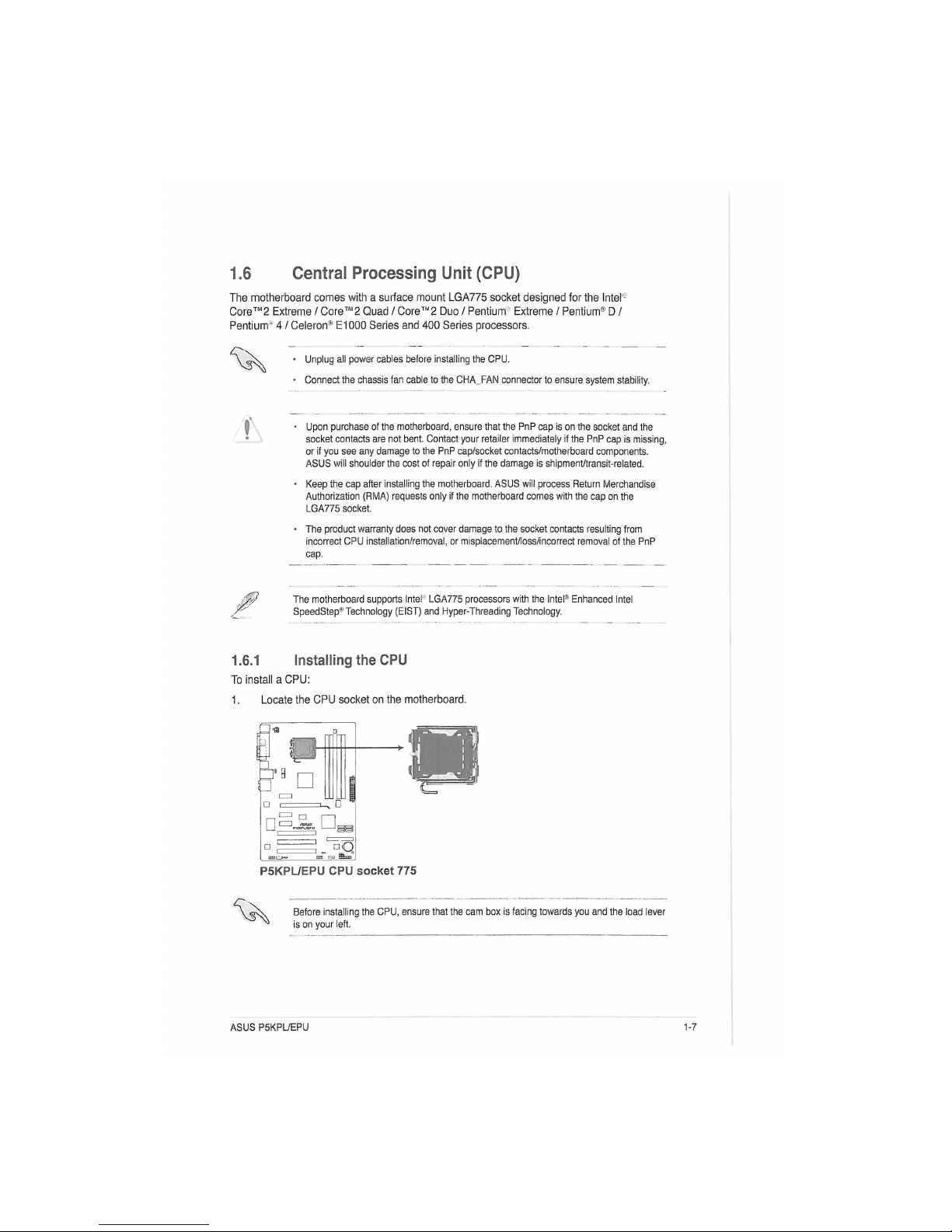
1.6.1 Installing the CPU
To install a CPU:
1. Locate the CPU socket on the motherboard.
• ^ | aQ
P5KPL/EPU CPU socket 775
Before installing the CPU, ensure that the cam box is facing towards you and the load lever
is on your left.
ASUS P5KPL/EPU
1-7
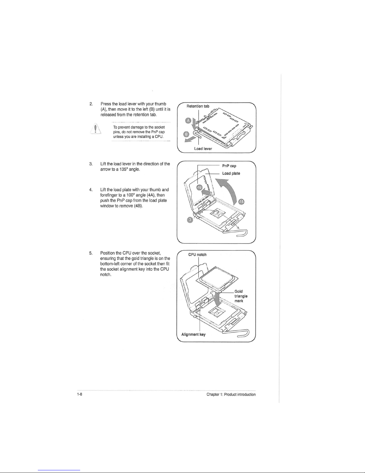
Press the load lever with your thumb
(A), then move it to the left (B) until it is
released from the retention tab.
To prevent damage to the socket
pins, do not remove the PnP cap
unless you are installing a CPU.
PnP
cap
Load plate
Lift the load lever in the direction of the
arrow to a 135° angle.
Lift the load plate with your thumb and
forefinger to a 100° angle (4A), then
push the PnP cap from the load plate
window to remove (4B).
Position the CPU over the socket,
ensuring that the gold triangle is on the
bottom-left corner of the socket then fit
the socket alignment key into the CPU
notch.
V У
1-20 Chapter 1: Product introduction
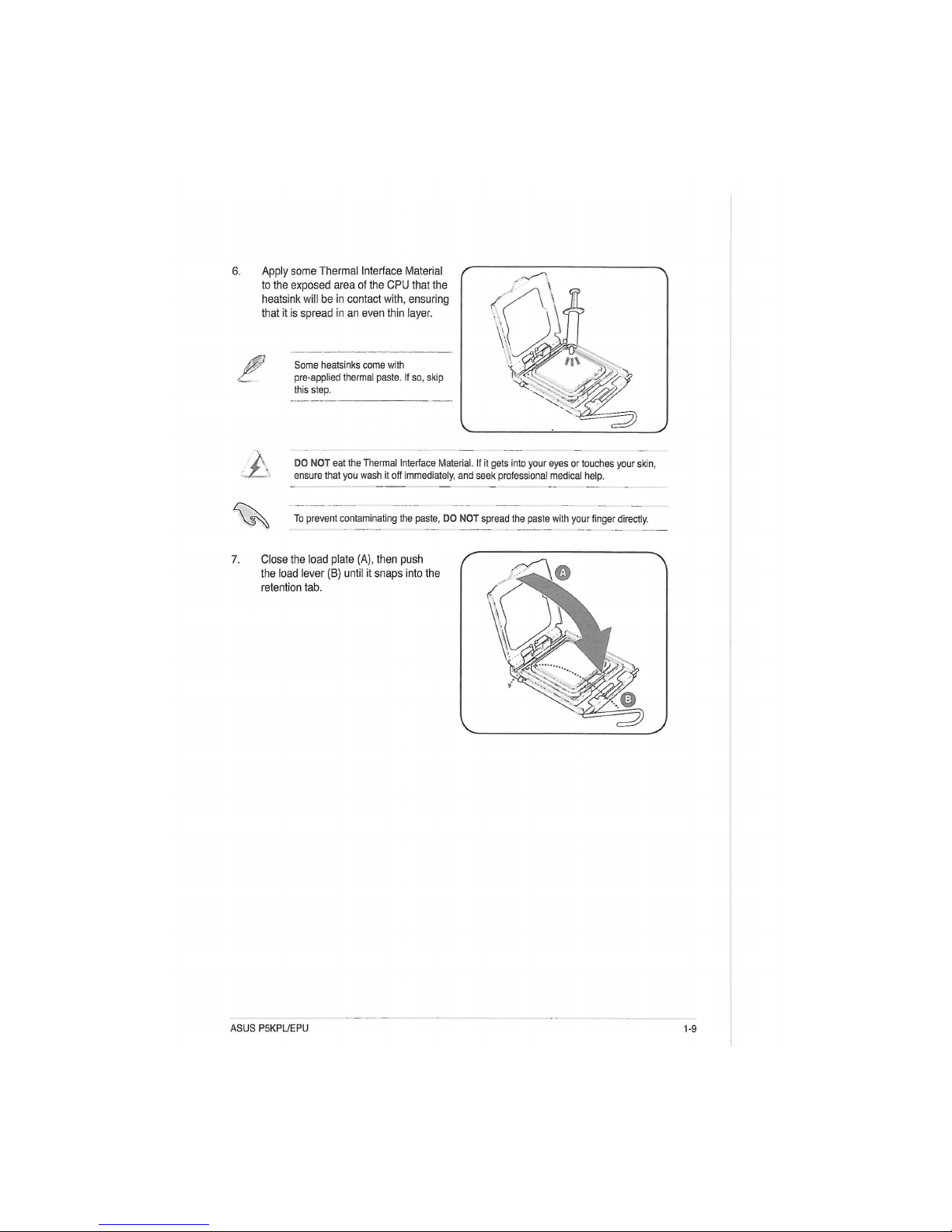
Apply some Thermal Interface Material
to the exposed area of the CPU that the
heatsink will be in contact with, ensuring
that it is spread in an even thin layer.
Some heatsinks come with
pre-applied thermal paste. If so, skip
this step.
A
DO NOT eat the Thermal Interface Material. If it gets into your eyes or touches your skin,
ensure that you wash it off immediately, and seek professional medical help.
To prevent contaminating the paste, DO NOT spread the paste with your finger directly.
ASUS P5KPL/EPU
1-9
 Loading...