


ALiveXFire-eSATA2
11
11
1
ASRock ALiveXFire-eSATA2 Motherboard
EnglishEnglish
EnglishEnglish
English
Copyright Notice:Copyright Notice:
Copyright Notice:Copyright Notice:
Copyright Notice:
No part of this installation guide may be reproduced, transcribed, transmitted, or trans-
lated in any language, in any form or by any means, except duplication of documen-
tation by the purchaser for backup purpose, without written consent of ASRock Inc.
Products and corporate names appearing in this guide may or may not be registered
trademarks or copyrights of their respective companies, and are used only for identifica-
tion or explanation and to the owners’ benefit, without intent to infringe.
Disclaimer:Disclaimer:
Disclaimer:Disclaimer:
Disclaimer:
Specifications and information contained in this guide are furnished for informational
use only and subject to change without notice, and should not be constructed as a
commitment by ASRock. ASRock assumes no responsibility for any errors or omissions
that may appear in this guide.
With respect to the contents of this guide, ASRock does not provide warranty of any kind,
either expressed or implied, including but not limited to the implied warranties or
conditions of merchantability or fitness for a particular purpose. In no event shall
ASRock, its directors, officers, employees, or agents be liable for any indirect, special,
incidental, or consequential damages (including damages for loss of profits, loss of
business, loss of data, interruption of business and the like), even if ASRock has been
advised of the possibility of such damages arising from any defect or error in the guide
or product.
This device complies with Part 15 of the FCC Rules. Operation is subject to the
following two conditions:
(1) this device may not cause harmful interference, and
(2) this device must accept any interference received, including interference that
may cause undesired operation.
Published December 2007
Copyright©2007 ASRock INC. All rights reserved.
CALIFORNIA, USA ONLY
The Lithium battery adopted on this motherboard contains Perchlorate, a toxic
substance controlled in Perchlorate Best Management Practices (BMP) regulations
passed by the California Legislature. When you discard the Lithium battery in
California, USA, please follow the related regulations in advance.
“Perchlorate Material-special handling may apply, see
www.dtsc.ca.gov/hazardouswaste/perchlorate”
ASRock Website: http://www.asrock.com
22
22
2
ASRock ALiveXFire-eSATA2 Motherboard
EnglishEnglish
EnglishEnglish
English
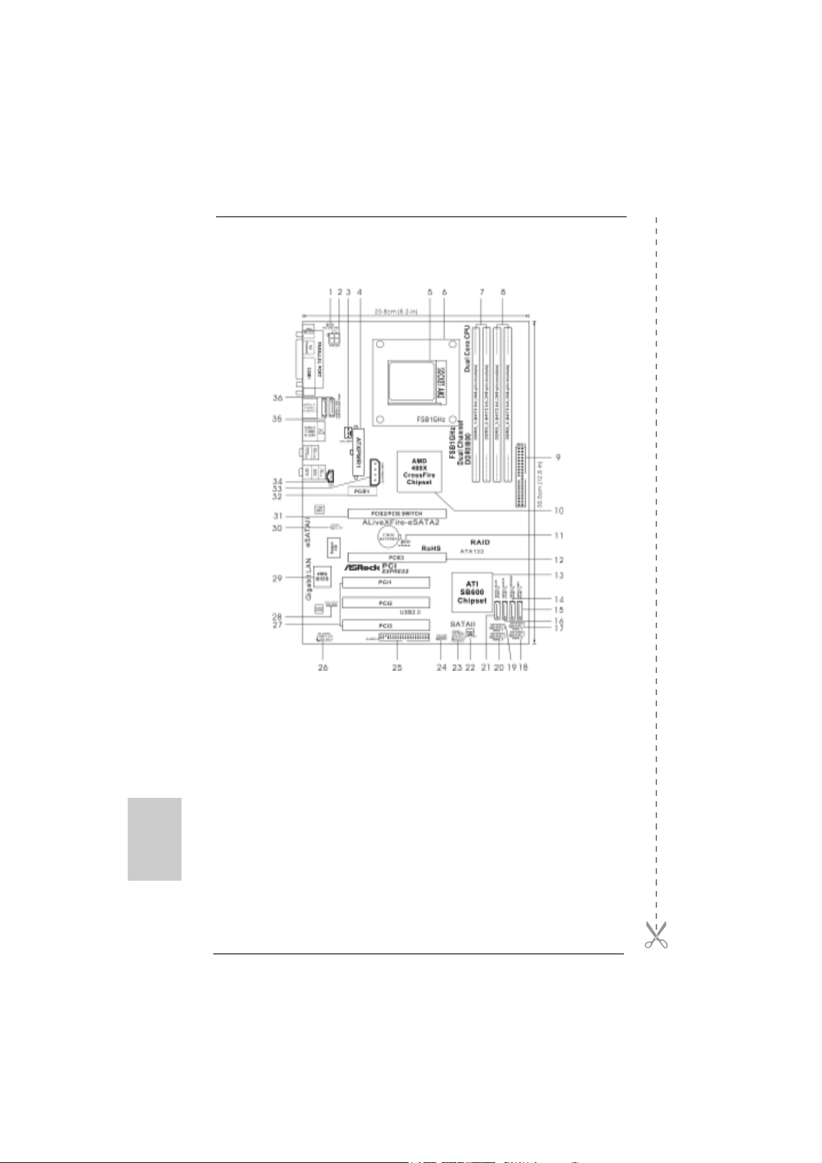
Motherboard LMotherboard L
Motherboard LMotherboard L
Motherboard L
ayoutayout
ayoutayout
ayout
1 PS2_USB_PW1 Jumper 19 USB 2.0 Header (USB6_7, Blue)
2 ATX 12V Connector (ATX12V1) 20 USB 2.0 Header (USB8_9, Blue)
3 CPU Fan Connector (CPU_FAN1) 21 Serial ATAII Connector
4 ATX Power Connector (ATXPWR1) (SATAII_BLUE (PORT 4))
5 AM2 940-Pin CPU Socket 22 Chassis Fan Connector (CHA_FAN1)
6 CPU Heatsink Retention Module 23 System Panel Header (PANEL1)
7 2 x 240-pin DDR2 DIMM Slots 24 Chassis Speaker Header (SPEAKER 1)
(Dual Channel A: DDRII_1, DDRII_2; Yellow) 25 Floppy Connector (FLOPPY1)
8 2 x 240- p in DD R2 DI MM Sl ot s 26 Front Panel Audio Header (HD_AUDIO1)
(Dual Channel B: DDRII_3, DDRII_4; Orange) 27 PCI Slots (PCI1- 3)
9 IDE1 Connector (IDE1, Blue) 28 HDMI_SPDIF Header (HDMI_SPDIF1)
10 North Bridge Controller 29 BIOS LPC Chip
11 Clear CMOS Jumper (CLRCMOS1) 30 Infrared Module Connector (IR1)
12 PCI Express x16 Slot (PCIE3) 31 PCIE Express Slot (PCIE2/PCIE SWITCH)
13 South Bridge Controller 32 PCI Express x1 Slot (PCIE1)
14 Serial ATAII Connector (SATAII_ORANGE (PORT 2))33 SLI / XFIRE Power Connector
15 Serial ATAII Connector (SATAII_RED (PORT 1)) 34 Internal Audio Connector: CD1 (Black)
16 Serial ATAII Connector (SATAII_BLACK (PORT 3)) 35 eSATAII Connector (eSATAII_TOP)
17 USB 2.0 Header (USB2_3, Blue) 36 eSATAII Connector (eSATAII_BOTTOM)
18 USB 2.0 Header (USB4_5, Blue)
33
33
3
ASRock ALiveXFire-eSATA2 Motherboard
EnglishEnglish
EnglishEnglish
English
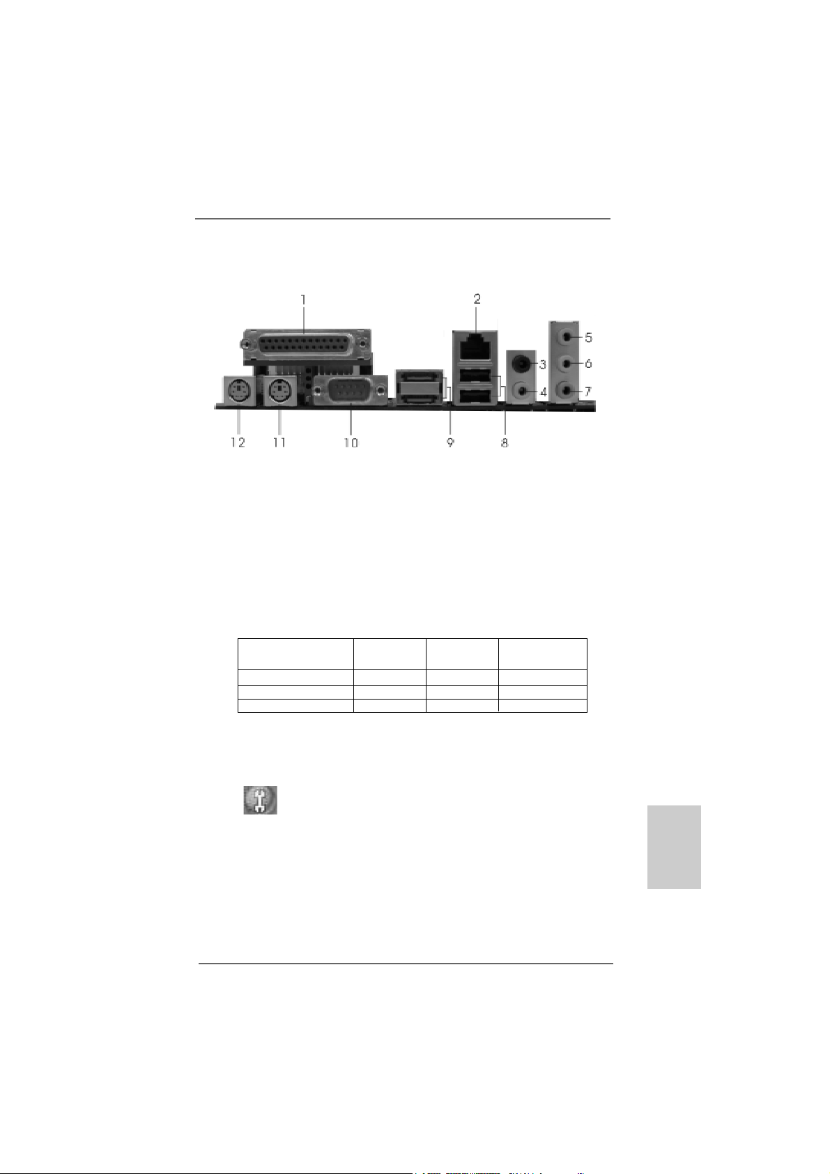
ASRASR
ASRASR
ASR
ock 6CH_eSAock 6CH_eSA
ock 6CH_eSAock 6CH_eSA
ock 6CH_eSA
TT
TT
T
AII I/OAII I/O
AII I/OAII I/O
AII I/O
1 Parallel Port 7 Microphone (Pink)
2 RJ-45 Port 8 USB 2.0 Ports (USB01)
3 Rear Speaker (Black) 9 eSATAII Ports
4 Central / Bass (Orange) 10 COM Port
5 Line In (Light Blue) 11 PS/2 Keyboard Port (Purple)
* 6 Front Speaker (Lime) 12 PS/2 Mouse Port (Green)
* If you use 2-channel speaker, please connect the speaker’s plug into “Front Speaker Jack”.
See the table below for connection details in accordance with the type of speaker you use.
TABLE f or Audio Output Connection
* To enable Multi-Streaming function, you need to connect a front panel audio cable to the front
panel audio header. Please refer to below steps for the software setting of Multi-Streaming.
For Windows
®
XP:
After restarting your computer, you will find “Mixer” tool on your system. Please select “Mixer
ToolBox” , click “Enable playback multi-streaming”, and click “ok”. Choose “2CH” or
“4CH” and then you are allowed to select “Realtek HDA Primary output” to use Rear Speaker
and Front Speaker, or select “Realtek HDA Audio 2nd output” to use front panel audio. Then
reboot your system.
For Windows
®
Vista
TM
:
After restarting your computer, please double-click “Realtek HD Audio Manager” on the
system tray. Set “Speaker Configuration” to “5.1 Speaker”. Click “Device advanced settings”,
choose “Make front and rear output devices playbacks two different audio streams
simultaneously”, and click “ok”. Then reboot your system.
Audio Output Channels Front Speaker Rear Speaker Central / Bass
(No. 6) (No. 3) (No. 4)
2 V -- --
4VV--
6VVV
44
44
4
ASRock ALiveXFire-eSATA2 Motherboard
1.1.
1.1.
1.
IntroductionIntroduction
IntroductionIntroduction
Introduction
Thank you for purchasing ASRock ALiveXFire-eSATA2 motherboard, a reliable
motherboard produced under ASRock’s consistently stringent quality control. It de-
livers excellent performance with robust design conforming to ASRock’s commit-
ment to quality and endurance.
This Quick Installation Guide contains introduction of the motherboard and step-by-
step installation guide. More detailed information of the motherboard can be found in
the user manual presented in the Support CD.
Because the motherboard specifications and the BIOS software might
be updated, the content of this manual will be subject to change without
notice. In case any modifications of this manual occur, the updated
version will be available on ASRock website without further notice. You
may find the latest VGA cards and CPU support lists on ASRock
website as well.
ASRock website http://www.asrock.com
If you require technical support related to this motherboard, please
visit our website for specific information about the model you are
using.
www.asrock.com/support/index.asp
1.11.1
1.11.1
1.1
PP
PP
P
ackack
ackack
ack
age Contentsage Contents
age Contentsage Contents
age Contents
1 x ASRock ALiveXFire-eSATA2 Motherboard
(ATX Form Factor: 12.0-in x 8.2-in, 30.5 cm x 20.8 cm)
1 x ASRock ALiveXFire-eSATA2 Quick Installation Guide
1 x ASRock ALiveXFire-eSATA2 Support CD
1 x Ultra A TA 66/100/133 IDE Ribbon Cable (80-conductor)
1 x 3.5-in Floppy Drive Ribbon Cable
2 x Serial AT A (SATA) Data Cables (Optional)
1 x Serial AT A (SATA) HDD Power Cable (Optional)
1 x HDMI_SPDIF Cable (Optional)
1 x ASRock 6CH_eSATAII I/O Shield
1 x USB Bracket
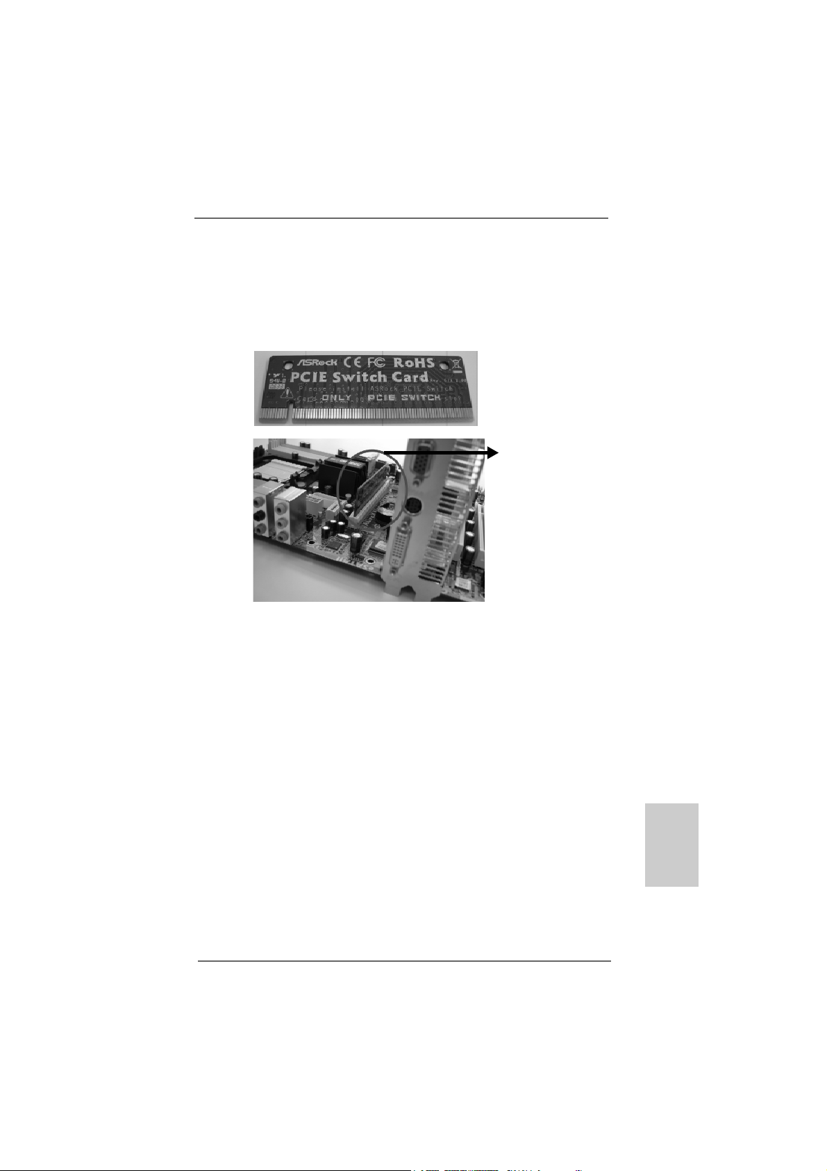
1 x PCIE Switch Card
This motherboard is bundled with one PCIE Switch card installed on PCIE2/
PCIE SWITCH slot, which allows you better flexibility to choose PCIE
functions between one PCIE x16 slot and two PCIE slots for ATI
TM
CrossFire
TM
without setting up jumpers.
EnglishEnglish
EnglishEnglish
English

55
55
5
ASRock ALiveXFire-eSATA2 Motherboard
EnglishEnglish
EnglishEnglish
English
1.21.2
1.21.2
1.2
SpecificationsSpecifications
SpecificationsSpecifications
Specifications
Platform - ATX Form Factor: 12.0-in x 8.2-in, 30.5 cm x 20.8 cm
CPU - Socket AM2 for AMD Phenom
TM
X4 / X2, Athlon 64FX / 64X2 /
X2 / 64 and Sempron processors
- AMD LIVE!
TM
Ready
- Supports AMD’s Cool ‘n’ Quiet
TM
T echnology
- FSB 1000 MHz (2.0 GT/s)
- Supports Untied Overclocking Technology (see CAUTION 1)
- Supports Hyper-Tran sport Technology
Chipset - Northbridge: AMD 480X CrossFire
TM
- Southbridge:ATI
TM
SB600
Memory - Dual Channel DDR2 Memory Technology (see CAUTION 2)
- 4 x DDR2 DIMM slots
- Support DDR2 1066/800/667/533 (see CAUTION 3)
- Max. capacity: 16GB (see CAUTION 4)
Hybrid Booster - CPU Frequency Stepless Control (see CAUTION 5)
- ASRock U-COP (see CAUTION 6)
- Boot Failure Guard (B.F.G.)
- AM2 Boost: ASRock Patented T e chnology to boost memory
performance up to 12.5% (see CAUTION 7)
Expansion Slot - Supports ATI
TM
CrossFire
TM
graphics cards
(see CAUTION 8)
- 1 x PCI Express x16 slot with PCIE Switch card or 2 x PCI
Express Graphics slots for ATI
TM
CrossFire
TM
(see CAUTION 9)
- 1 x PCI Express x1 slot
- 3 x PCI slots
Audio - 5.1 CH Windows
®
Vista
TM
Premium Level HD Audio
(ALC662 Audio Codec)
LAN - PCIE x1 Gigabit LAN 10/100/1000 Mb/s
- Realtek RTL81 1 1B
- Supports Wa ke-On-LAN
Rear Panel I/O ASRock 6CH_eSA T AII I/O
- 1 x PS/2 Mouse Port
- 1 x PS/2 Keyboard Port
- 1 x Serial Port: COM1
- 1 x Parallel Port (ECP/EPP Support)
- 2 x Ready-to-Use USB 2.0 Ports
- 2 x eSATAII Ports
- 1 x RJ-45 Port

66
66
6
ASRock ALiveXFire-eSATA2 Motherboard
EnglishEnglish
EnglishEnglish
English
- HD Audio Jack: Rear Spea ker / Central/Bass / Line in / Front
Speaker / Microphone (see CAUTION 10)
Connector - 4 x SATAII 3.0Gb/s connectors, support RAID (RAID 0,
RAID 1 a nd RAID 10), NCQ, AHCI and “Hot Plug” functions
(see CAUTION 11)
- 2 x eSATAII 3.0Gb/s connectors (shared with 2 SATAII ports),
support RAID (RAID 0 a nd RAID 1), NCQ, AHCI and “Hot Plug”
functions (see CAUTION 12)
- 1 x ATA133 IDE connector (supports 2 x IDE devices)
- 1 x Floppy connector
- 1 x IR header
- 1 x HDMI_SPDIF header
- CPU/Chassis FAN connector
- 20 pin A TX power conne ctor
- 4 pin 12V power connector
- SLI/XFire power connector
- CD in header
- Front panel audio connector
- 4 x USB 2.0 headers (support 8 USB 2.0 ports)
(see CAUTION 13)
BIOS Feature - 4Mb AMI BIOS
- AMI Legal BIOS
- Supports “Plug and Play”
- ACPI 1.1 Compliance Wake Up Events
- Supports jumperfree
- SMBIOS 2.3.1 Support
Support CD - Drivers, Utilities, AntiVirus Software (Trial Version)
Hardware - CPU T e mperature Sensing
Monitor - Chassis Temperature Sensing
- CPU Fan Tachometer
- Chassis Fa n Tachometer
- CPU Quiet Fan
- Voltage Monitoring: +12V, +5V, +3.3V, Vcore
OS - Microsoft
®
Windows
®
2000 / XP / XP Media Center / XP 64-bit
/ Vista
TM
/ Vista
TM
64-bit compliant
Certifications - FCC, CE, Microsoft
®
WHQL Certificated

77
77
7
ASRock ALiveXFire-eSATA2 Motherboard
EnglishEnglish
EnglishEnglish
English
WARNING
Please realize that there is a certain risk involved with overclocking, including adjusting
the setting in the BIOS, applying Untied Overclocking Technology, or using the third-
party overclocking tools. Overclocking may affect your system stability, or even
cause damage to the components and devices of your system. It should be done at
your own risk and expense. We are not responsible for possible damage caused by
overclocking.
CAUTION!
1. This motherboard supports Untied Overclocking Technology. Please read
“Untied Overclocking Technology” on page 37 for details.
2. This motherboard supports Dual Channel Memory Technology. Before
you implement Dual Channel Memory Technology, make sure to read
the installation guide of memory modules on page 11 for proper
installation.
3. Whether 1066MHz memory speed is supported depends on the AM2+
CPU you adopt. If you want to adopt DDR2 1066 memory module on this
motherboard, please refer to the memory support list on our website for
the compatible memory modules.
ASRock website http://www.asrock.com
4. Due to the operating system and chipset limitation, the actual memory
size may be less than 4GB for the reservation for system usage under
Windows
®
XP, Windows
®
Vista
TM
, and Windows
®
Vista
TM
64-bit. For
Windows
®
XP 64-bit with 64-bit CPU, there is no such limitation.
5. Although this motherboard offers stepless control, it is not recommended to
perform over-clocking. Frequencies other than the recommended CPU bus
frequencies may cause the instability of the system or damage the CPU.
6. While CPU overheat is detected, the system will automatically shutdown.
Before you resume the system, please check if the CPU fan on the
motherboard functions properly and unplug the power cord, then plug it
back again. To improve heat dissipation, remember to spray thermal grease
between the CPU and the heatsink when you install the PC system.
7. This motherboard supports ASRock AM2 Boost overclocking technology. If
you enable this function in the BIOS setup, the memory performance will
improve up to 12.5%, but the effect still depends on the AM2 CPU you
adopt. Enabling this function will overclock the chipset/CPU reference clock.
However, we can not guarantee the system stability for all CPU/DRAM
configurations. If your system is unstable after AM2 Boost function is enabled,
it may not be applicative to your system. You may choose to disable this
function for keeping the stability of your system.
8. Please remove PCIE Switch card from PCIE2/PCIE SWITCH slot before
you use ATI
TM
CrossFire
TM
function. In CrossFire
TM
mode, the two ATI
TM
graph-
ics cards you install should be from the same GPU family.

88
88
8
ASRock ALiveXFire-eSATA2 Motherboard
EnglishEnglish
EnglishEnglish
English
9. This motherboard is bundled with one PCIE Switch card installed on PCIE2/
PCIE SWITCH slot, which allows you better flexibility to choose PCIE func-
tions between one PCIE x16 slot and two PCIE slots for ATI
TM
CrossFire
TM
without setting up jumpers. To avail of the PCI Express x16 graphics card
installed on PCIE3 slot work at PCIE x16 bandwidth, please make sure that
PCIE Switch card is installed on PCIE2/PCIE SWITCH slot. Please refer to
page 15 for details of installing a single graphics card.
10. For microphone input, this motherboard supports both stereo and mono
modes. For audio output, this motherboard supports 2-channel, 4-channel
and 6-channel modes. Please check the table on page 3 for proper
connection.
11. Before installing SATAII hard disk to SATAII connector, please read the “SA TAII
Hard Disk Setup Guide” on page 30 to adjust your SATAII hard disk drive to
SATAII mode. You can also connect SATA hard disk to SATAII connector
directly.
12. This motherboard supports eSATAII interface, the external SATAII
specification. Please read “eSATAII Interface Introduction” on page 27
for details about eSATAII and eSATAII installation procedures.
13. Power Management for USB 2.0 works fine under Microsoft
®
Windows
®
Vista
TM
64-bit / Vista
TM
/ XP 64-bit / XP SP1 or SP2 / 2000 SP4.
1.31.3
1.31.3
1.3
Minimum Hardware RMinimum Hardware R
Minimum Hardware RMinimum Hardware R
Minimum Hardware R
equirement Tequirement T
equirement Tequirement T
equirement T
able for Wable for W
able for Wable for W
able for W
indowsindows
indowsindows
indows
®®
®®
®
VistaVista
VistaVista
Vista
TMTM
TMTM
TM
Premium 2007 and Basic Logo Premium 2007 and Basic Logo
Premium 2007 and Basic Logo Premium 2007 and Basic Logo
Premium 2007 and Basic Logo
For system integrators and users who purchase this motherboard and
plan to submit Windows
®
Vista
TM
Premium 2007 and Basic logo, please
follow below table for minimum hardware requirements.
CPU Sempron 2800+
Memory 1GB system memory (Premium)
512MB Single Channel (Basic)
VGA DX9.0 with WDDM Driver
with 128bit VGA memory (Premium)
with 64bit VGA memory (Basic)
* After June 1, 2007, all Windows
®
Vista
TM
systems are required to meet above
minimum hardware requirements in order to qualify for Windows
®
Vista
TM
Premium
2007 logo.
99
99
9
ASRock ALiveXFire-eSATA2 Motherboard
EnglishEnglish
EnglishEnglish
English
2.2.
2.2.
2.
InstallationInstallation
InstallationInstallation
Installation
This is an ATX form factor (12.0-in x 8.2-in, 30.5 cm x 20.8 cm) motherboard.
Before you install the motherboard, study the configuration of your chassis to en-
sure that the motherboard fits into it.
Pre-installation PrecautionsPre-installation Precautions
Pre-installation PrecautionsPre-installation Precautions
Pre-installation Precautions
Take note of the following precautions before you install motherboard
components or change any motherboard settings.
Before you install or remove any component, ensure that the
power is switched off or the power cord is detached from the
power supply. Failure to do so may cause severe damage to the
motherboard, peripherals, and/or components.
1. Unplug the power cord from the wall socket before touching any
component.
2. To avoid damaging the motherboard components due to static
electricity, NEVER place your motherboard directly on the carpet or
the like. Also remember to use a grounded wrist strap or touch a
safety grounded object before you handle components.
3. Hold components by the edges and do not touch the ICs.
4. Whenever you uninstall any component, place it on a grounded anti-
static pad or in the bag that comes with the component.
5. When pla cing screws into the screw holes to se cure the motherboard
to the chassis, please do not over-tighten the screws! Doing so may
damage the motherboard.

1010
1010
10
ASRock ALiveXFire-eSATA2 Motherboard
2.12.1
2.12.1
2.1
CPU InstallationCPU Installation
CPU InstallationCPU Installation
CPU Installation
Step 1. Unlock the socket by lifting the lever up to a 90
o
angle.
Step 2. Position the CPU directly above the socket such that the CPU corner with
the golden triangle matches the socket corner with a small triangle.
Step 3. Carefully insert the CPU into the socket until it fits in place.
The CPU fits only in one correct orientation. DO NOT force the CPU
into the socket to avoid bending of the pins.
Step 4. When the CPU is in place, press it firmly on the socket while you push
down the socket lever to secure the CPU. The lever clicks on the side tab
to indicate that it is locked.
2.22.2
2.22.2
2.2
Installation of CPU Fan and HeatsinkInstallation of CPU Fan and Heatsink
Installation of CPU Fan and HeatsinkInstallation of CPU Fan and Heatsink
Installation of CPU Fan and Heatsink
After you install the CPU into this motherboard, it is necessary to install a
larger heatsink and cooling fan to dissipate heat. You also need to spray
thermal grease between the CPU and the heatsink to improve heat
dissipation. Make sure that the CPU and the heatsink are securely fas-
tened and in good contact with each other. Then connect the CPU fan to
the CPU FAN connector (CPU_FAN1, see Page 2, No. 3). For proper
installation, please kindly refer to the instruction manuals of the CPU fan
and the heatsink.
STEP 1:
Lift Up The Socket Lever
STEP 2 / STEP 3:
Match The CPU Golden Triangle
To The Socket Corner Small
Triangle
STEP 4:
Push Down And Lock
The Socket Lever
Lever 90° Up
CPU Golden Triangle
Socket Corner Small Triangle
EnglishEnglish
EnglishEnglish
English
1111
1111
11
ASRock ALiveXFire-eSATA2 Motherboard
EnglishEnglish
EnglishEnglish
English
2.3 Installation of Memor2.3 Installation of Memor
2.3 Installation of Memor2.3 Installation of Memor
2.3 Installation of Memor
y Modules (DIMM)y Modules (DIMM)
y Modules (DIMM)y Modules (DIMM)
y Modules (DIMM)
This motherboard provides four 240-pin DDR2 (Double Data Rate 2) DIMM slots,
and supports Dual Channel Memory Technology . For dual channel configuration,
you always need to install identical (the same brand, speed, size and chip-type)
DDR2 DIMM pair in the slots of the same color. In other words, you have to install
identical DDR2 DIMM pair in Dual Cha nnel A (DDRII_1 a nd DDRII_2; Yellow slots;
see p.2 No.7) or identical DDR2 DIMM pair in Dual Channel B (DDRII_3 and
DDRII_4; Orange slots; see p.2 No.8), so that Dual Channel Memory Technology
can be a ctivated. This motherboard also allows you to install f our DD R2 DIMMs f or
dual channel configuration, and please install identical DDR2 DIMMs in all four
slots. Y ou may refer to the Dual Channel Memory Configuration Table below .
Dual Channel Memory Configurations
DDRII_1 DDRII_2 DDRII_3 DDRII_4
(Y ellow Slot) (Yellow Slot) (Orange Slot) (Ora nge Slot)
(1) Populated Populated - -
(2) - - Populated Populated
(3)* Populated Populated Populated Populated
* For the configuration (3), please install identical DDR2 DIMMs in all four slots.
1. If you want to install two memory modules, for optimal compatibil-
ity and reliability, it is recommended to install them in the slots of
the same color. In other words, install them either in the set of
yellow slots (DDRII_1 and DDRII_2), or in the set of orange slots
(DDRII_3 and DDRII_4).
2. If only one memory module or three memory modules are in-
stalled in the DDR2 DIMM slots on this motherboard, it is unable to
activate the Dual Channel Memory Technology.
3. If a pair of memory modules is NOT installed in the same Dual
Channel, for example, installing a pair of memory modules in
DDRII_1 and DDRII_3, it is unable to activate the Dual Channel
Memory Technology .
4. It is not allowed to install a DDR memory module into DDR2 slot;
otherwise, this motherboard and DIMM may be damaged.

1212
1212
12
ASRock ALiveXFire-eSATA2 Motherboard
EnglishEnglish
EnglishEnglish
English
Installing a DIMMInstalling a DIMM
Installing a DIMMInstalling a DIMM
Installing a DIMM
Please make sure to disconnect power supply before adding or
removing DIMMs or the system components.
Step 1. Unlock a DIMM slot by pressing the retaining clips outward.
Step 2. Align a DIMM on the slot such that the notch on the DIMM matches the break
on the slot.
The DIMM only fits in one correct orientation. It will cause permanent
damage to the motherboard and the DIMM if you force the DIMM into the
slot at incorrect orientation.
Step 3. Firmly insert the DIMM into the slot until the retaining clips at both ends fully
snap back in place and the DIMM is properly seated.
1313
1313
13
ASRock ALiveXFire-eSATA2 Motherboard
EnglishEnglish
EnglishEnglish
English
2.4 Expansion Slots (PCI and PCI Express Slots)2.4 Expansion Slots (PCI and PCI Express Slots)
2.4 Expansion Slots (PCI and PCI Express Slots)2.4 Expansion Slots (PCI and PCI Express Slots)
2.4 Expansion Slots (PCI and PCI Express Slots)
There are 3 PCI slots and 3 PCI Express slots on this motherboard.
PCI slots: PCI slots are used to install expansion cards that have the 32-bit PCI
interface.
PCIE Slots: PCIE1 slot (PCI Express x1 slot) is used for PCI Express cards with
x1 lane width, such as Gigabit LAN card, SATA2 card, etc.
For PCIE2/PCIE SWITCH slot and PCIE3 slot, you may choose to use
one PCI Express x16 slot with PCIE Switch card or two PCI Express
Graphics slots for ATI
TM
CrossFire
TM
.
NOTE:
If you want the PCI Express x16 graphics card on PCIE3 slot to work at PCIE
x16 bandwidth, you need to install PCIE Switch card on PCIE2/PCIE SWITCH
slot. Please refer to page 15 for details of installing a single graphics card.
If you want to enable ATI
TM
CrossFire
TM
feature, please refer to page 16 for
details of installing CrossFire
TM
graphics cards.
Plea se refer to the table below for possible PCIE2/PCIE SWITCH slot
and PCIE3 slot configurations.
PCIE2/PCIE Switch Slot and PCIE3 Slot Configurations
PCIE2/PCIE SWITCH Slot PCIE3 Slot
Card Type Card Type
Single Graphics Card * PCIE Switch Card PCIE x16 graphics card
Dual Graphics Cards
in CrossFire
TM
Mode **
ATI
TM
Standard Radeon
(CrossFire
TM
Ready)
graphics card
ATI
TM
Radeon CrossFire
TM
Edition graphics card
* To avail of the PCI Express x16 graphics card installed on PCIE3 slot work at
PCIE x16 bandwidth, please make sure that PCIE Switch card is installed on
PCIE2/PCIE SWITCH slot. Please refer to page 15 for details of installing a
single graphics card.
** Please remove PCIE Switch card from PCIE2/PCIE SWITCH slot before you
use ATI
TM
CrossFire
TM
function. In CrossFire
TM
mode, the two ATI
TM
graphics
cards you install should be from the same GPU family.

1414
1414
14
ASRock ALiveXFire-eSATA2 Motherboard
EnglishEnglish
EnglishEnglish
English
Installing an expansion cardInstalling an expansion card
Installing an expansion cardInstalling an expansion card
Installing an expansion card
Step 1. Before installing the expansion card, please make sure that the power
supply is switched off or the power cord is unplugged. Please read the
documentation of the expansion card and make necessary hardware
settings for the card before you start the installation.
Step 2. Remove the system unit cover (if your motherboard is already installed in
a chassis).
Step 3. Re move the bracket facing the slot that you intend to use. Keep the
screws for later use.
Step 4. Align the card connector with the slot and press firmly until the card is
completely seated on the slot.
Step 5. Fasten the card to the chassis with screws.
Step 6. Replace the system cover.
1515
1515
15
ASRock ALiveXFire-eSATA2 Motherboard
EnglishEnglish
EnglishEnglish
English
2.5 Installing a Single Graphics Card2.5 Installing a Single Graphics Card
2.5 Installing a Single Graphics Card2.5 Installing a Single Graphics Card
2.5 Installing a Single Graphics Card
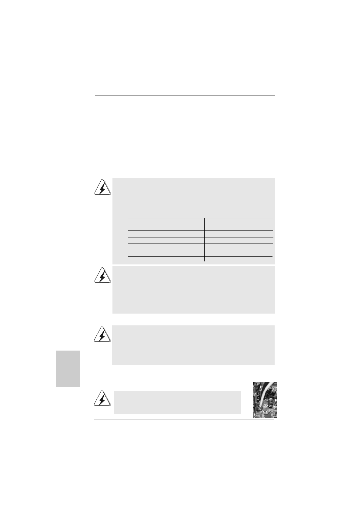
Step 1. Install a PCI Express x16 graphics card on PCIE3 slot. Please refer to
page 14 for proper procedures of installing an expansion card.
Step 2. Make sure that the PCIE Switch card is installed on PCIE2/PCIE SWITCH
slot to avail of the PCI Express x16 graphics card full x16 bandwidth.
Step 3. Connect one end of the monitor cable to the PCI Express x16 graphics
card on PCIE3 slot.
Step 4. Connect another end of the monitor cable to the corresponding port on
your monitor.
Step 5. Connect an auxiliary power source from the power supply to the PCI
Express x16 graphics card on PCIE3 slot. (Only when your graphics
card provides such a power connector.)
PCIE Switch card
PCIE Switch card
on PCIE2/PCIE
SWITCH slot
1616
1616
16
ASRock ALiveXFire-eSATA2 Motherboard
EnglishEnglish
EnglishEnglish
English
2.6 Installing CrossFire2.6 Installing CrossFire
2.6 Installing CrossFire2.6 Installing CrossFire
2.6 Installing CrossFire
TMTM
TMTM
TM
Graphics Cards Graphics Cards
Graphics Cards Graphics Cards
Graphics Cards
This motherboard supports CrossFire
TM
feature. CrossFire
TM
technology offers the
most advantageous mea n s availa ble of combining multiple high perf ormance Gra phics
Processing Units (GPU) in a single PC. Combining a range of different operating
modes with intelligent software design and an innovative interconnect mechanism,
CrossFire
TM
enables the highest possible level of performance and image quality in
any 3D application. Currently CrossFire
TM
feature is only supported with Windows
®
XP with Service Pack 2; it may be supported with other OS in the future, such as
Windows
®
Vista
TM
. Please check ATI
TM
website for driver updates.
1. If a customer incorrectly configures their system they will not see the
performance benefits of CrossFire
TM
. All three CrossFire
TM
components, a
CrossFire
TM
Ready graphics card, a CrossFire
TM
Ready motherboard and
a CrossFire
TM
Edition co-processor graphics card, must be installed
correctly to benefit from the CrossFire
TM
multi-GPU platform.
2. If you pair a 12-pipe CrossFire
TM
Edition card with a 16-pipe card, both
cards will operate as 12-pipe cards while in CrossFire
TM
mode.
Enjoy the benefit of CrossFireEnjoy the benefit of CrossFire
Enjoy the benefit of CrossFireEnjoy the benefit of CrossFire
Enjoy the benefit of CrossFire
TMTM
TMTM
TM
It is recommended to use 500-Watt power supply or greater
to perform the benefit of CrossFire
TM
feature for Radeon
X850XT, X1900 and X1950 series.
Step 1. Remove PCIE Switch card from PCIE2/PCIE SWITCH slot if one is installed.
Step 2. Connect to the system power supply. Please connect a hard disk power
connector to SLI/XFIRE Power connector on this motherboard.
What graphics cards work with CrossFire
TM
?
A complete CrossFire
TM
system requires a CrossFire
TM
Ready motherboard,
a CrossFire
TM
Edition graphics card and a compatible standard Radeon
(CrossFire
TM
Ready) graphics card from the same series, or two CrossFire
TM
Ready cards if they are software enabled. This applies to cards from ATI
TM
or
any of its partners.
Currently, A TI
TM
has relea sed Ra deon X850XT, X1800XT, X1900XT , X1950XT,
X1300, and X1600 CrossFire
TM
cards, which require different methods to
enable CrossFire
TM
feature. In the below procedures, we use Radeon
X850XT as the example graphics card. For other CrossFire
TM
cards that
ATI
TM
has released or will release in the future, please refer to ATI
TM
graphics
card manuals for detailed installation guide.
Cards For PCIE2/PCIE SWITCH Slot Cards For PCIE3 Slot
Radeon X1950 Series Radeon X1950 CrossFire
TM
Edition
Radeon X1900 Series Radeon X1900 CrossFire
TM
Edition
Radeon X1800 Series Radeon X1800 CrossFire
TM
Edition
Radeon X1600 Series Radeon X1600 Series
Radeon X1300 Series Radeon X1300 Series
Radeon X850 Series Radeon X850 CrossFire
TM
Edition
1717
1717
17
ASRock ALiveXFire-eSATA2 Motherboard
EnglishEnglish
EnglishEnglish
English
DVI-DMS cable DMS connector
DVI connector
1. You are allowed to install two CrossFire
TM
Edition graphics cards to both slots, or you
may use one CrossFire
TM
Edition graphics cards a nd a compatible standard Radeon
(CrossFire
TM
Ready) graphics card from the same series.
2. For A T I
TM
Radeon X1300 and X1600 series, there are no CrossFire
TM
Edition graphics
cards. You can still install two regular graphics cards from the same series (two
Radeon X1300 series cards or two Radeon X1600 series cards) on PCIE2/PCIE
SWITCH slot and PCIE3 slot to support CrossFire
TM
. Besides, please connect the
monitor cable to the graphics card on PCIE3 slot.
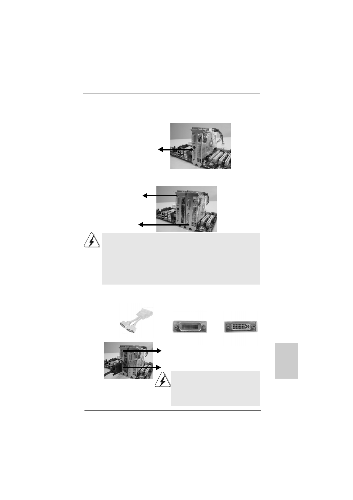
Step 3. Install the standard Radeon (CrossFire
TM
Ready) graphics card to PCIE2/
PCIE SWITCH slot. For the proper installation procedures, please refer to
section “Expansion Slots”.
Connect the DVI-DMS
cable to DVI connector of
the compatible standard
Radeon (CrossFire
TM
Ready) graphics card.
Standard Radeon
(CrossFire
TM
Ready)
graphics card
Standard Radeon
(CrossFire
TM
Ready)
graphics card
Radeon CrossFire
TM
Edition graphics card
D VI connector
Standard Radeon (CrossFire
TM
Ready)
graphics card
There are two DVI connectors on the
standard Radeon (CrossFire
TM
Ready)
graphics card. Please connect the DVI-DMS
cable to the correct DVI connector; otherwise
, the graphics card will not work.
Step 4. Install the Radeon CrossFire
TM
Edition graphics card to PCIE3 slot. For the
proper installation procedures, please refer to section “Expansion Slots”.
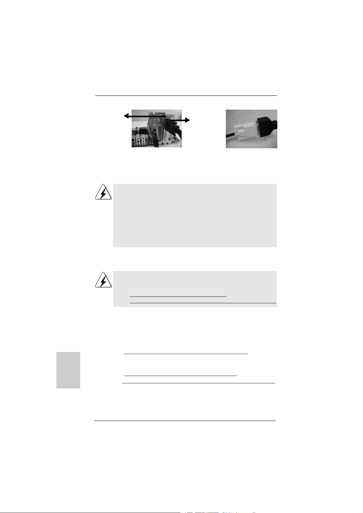
Step 5. Correctly connect the DVI-DMS cable to the monitor connector and two
graphics cards that you install. (If you install two standard Radeon
(CrossFire
TM
Ready) graphics cards to this motherboard, please skip this
step.)
1818
1818
18
ASRock ALiveXFire-eSATA2 Motherboard
EnglishEnglish
EnglishEnglish
English
Step 6. Power on your computer and boot into OS.
Step 7. Remove the A TI
TM
driver if you have any VGA driver installed in your system.
If you install two CrossFire
TM
Edition graphics cards to this motherboard, please
connect one end of DVI-DMS cable to the monitor, another end to DMS of one
of the CrossFire
TM
Edition graphics cards to PCIE3 slot, and the other end to
DVI of another CrossFire
TM
Edition graphics card to PCIE2/PCIE SWITCH slot.
If you install one CrossFire
TM
Edition graphics card and one compatible stan-
dard Radeon (CrossFire
TM
Ready) graphics card to this motherboard, please
connect one end of DVI-DMS cable to the monitor, another end to DMS of the
CrossFire
TM
Edition graphics card, and the other end to DVI of the compatible
standard Radeon (CrossFire
TM
Ready) graphics card.
Connect the DVI-DMS
cable to the monitor
connector.
Connect the DVI-DMS
cable to DMS connector
of the CrossFire
TM
Edition
graphics card.
The Catalyst Uninstaller is an optional download. We recommend using this
utility to uninstall any previously installed Catalyst drivers prior to installation.
Please visit this website for the driver:
http://support.ati.com/ics/support/DLRedirect.asp?
fileIDExt=050553d40196ef109fff37cbb40aaf28&accountID=737&deptID=894
Step 8. Install the required drivers to your system. Please visit the websites below
for installing the drivers that ATI
TM
recommends:
A. ATI
TM
recommends Windows
®
XP Service Pack 2 or higher to be
installed (If you have Windows
®
XP Service Pack 2 or higher installed
in your system, there is no need to download it again):
http://www.microsoft.com/windowsxp/sp2/default.mspx
B. You must have Microsoft .NET Framework installed prior to
downloading and installing the CATALYST Control Center:
http://www.microsoft.com/downloads/details.aspx?
FamilyId=262D25E3-F589-4842-8157-034D1E7CF3A3&displaylang=en
DMS
connector
Radeon
CrossFire
TM
Edition graphics
card
Step 9. Restart your computer.

1919
1919
19
ASRock ALiveXFire-eSATA2 Motherboard
EnglishEnglish
EnglishEnglish
English
t
t
If you install one Radeon CrossFire
TM
Edition graphics card a nd one compatible
standard Radeon (CrossFire
TM
Ready) graphics card to this motherboard but
not two Radeon CrossFire
TM
Edition graphics cards, please as well follow the
above steps. However, although you have selected the option “Enable
CrossFire
TM
”, the CrossFire
TM
function can not work actually. Your computer
will automatically reboot. After restarting your computer, please confirm whether
the option “Enable CrossFire
TM
” in “ATI Catalyst Control Center” is selected or
not; if not, please select it again, and then you are able to enjoy the benefit of
CrossFire
TM
feature.
Step 12. You can freely enjoy the benefit of CrossFire
TM
feature.
Step 11. Double-click “ATI Catalyst Control Center”. Click “View”, and select “Ad-
vanced View”. Click “CrossFire
TM
”, and then set the option “Enable
CrossFire
TM
” to “Yes”.
Step 10. Install the VGA card drivers to your system, and restart your computer.
Then you will find “ATI Catalyst Control Center” on your desktop.
You will find “ATI Catalyst
Control Center” on your
desktop.
View
CrossFire
TM
Enable CrossFire
TM
* CrossFire
TM
appearing here is a registered trademark of ATI
TM
Technologies Inc., and is used
only for identification or explanation and to the owners’ benefit, without intent to infringe.
2020
2020
20
ASRock ALiveXFire-eSATA2 Motherboard
EnglishEnglish
EnglishEnglish
English
Short Open
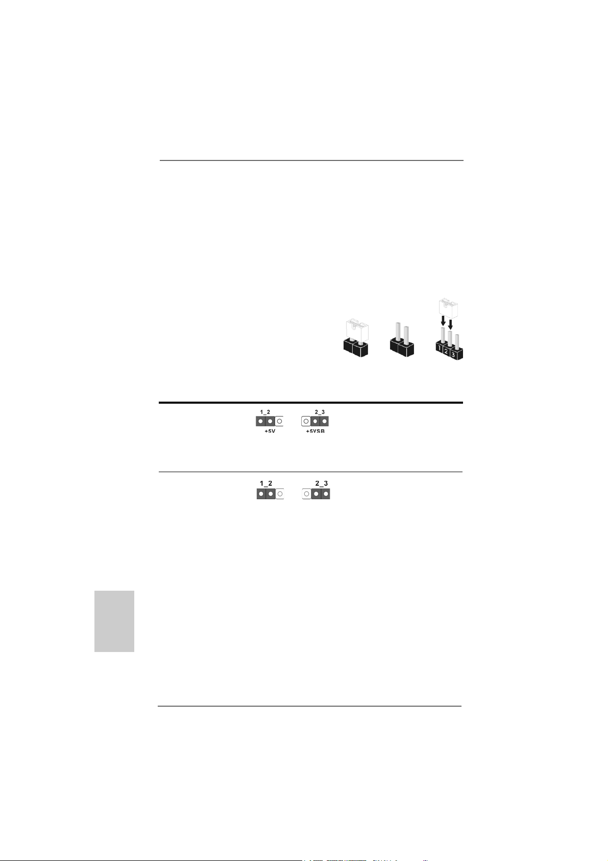
2.82.8
2.82.8
2.8
Jumpers SetupJumpers Setup
Jumpers SetupJumpers Setup
Jumpers Setup
The illustration shows how jumpers are
setup. When the jumper cap is placed on
pins, the jumper is “Short”. If no jumper cap
is placed on pins, the jumper is “Open”. The
illustration shows a 3-pin jumper whose pin1
and pin2 are “Short” when jumper cap is
placed on these 2 pins.
Jumper Setting
PS2_USB_PW1 Short pin2, pin3 to enable
(see p.2, No. 1) +5VSB (standby) for PS/2 or
USB wake up events.
Note: To select +5VSB, it requires 2 Amp and higher standby current provided by
power supply.
Clear CMOS Jumper
(CLRCMOS1)
(see p.2, No. 1 1)
Note: CLRCMOS1 allows you to clear the data in CMOS. The data in CMOS includes
system setup information such as system password, date, time, and system
setup parameters. To clear and reset the system parameters to default setup,
please turn off the computer and unplug the power cord from the power
supply. After waiting for 15 seconds, use a jumper cap to short pin2 and pin3
on CLRCMOS1 for 5 seconds. However, please do not clear the CMOS right
after you update the BIOS. If you need to clear the CMOS when you just finish
updating the BIOS, you must boot up the system first, and then shut it down
before you do the clear-CMOS action.
Clear CMOSDefault
2.7 Surround Display Feature2.7 Surround Display Feature
2.7 Surround Display Feature2.7 Surround Display Feature
2.7 Surround Display Feature
This motherboard supports Surround Display upgrade. With the external add-on
ATI PCI Express VGA cards, you can easily enjoy the benefits of Surround Display
feature. For the detailed instruction, please refer to the document at the following
path in the Support CD:
..\ Surround Display Information

2121
2121
21
ASRock ALiveXFire-eSATA2 Motherboard
EnglishEnglish
EnglishEnglish
English
2.9 Onboard Headers and Connectors2.9 Onboard Headers and Connectors
2.9 Onboard Headers and Connectors2.9 Onboard Headers and Connectors
2.9 Onboard Headers and Connectors
Onboard headers and connectors are NOT jumpers. Do NOT place
jumper caps over these headers and connectors. Placing jumper caps
over the headers and connectors will cause permanent damage of the
motherboard!
•
Floppy Connector
(33-pin FLOPPY1)
(see p.2 No. 25)
Note: Make sure the red-striped side of the cable is plugged into Pin1 side of the
connector.
Primary IDE connector (Blue)
(39-pin IDE1, see p.2 No. 9)
Note: Please re f e r t o t h e i n struction of your IDE device vendor for the details.
connect the black end
to the IDE devices
connect the blue end
to the motherboard
80-conductor ATA 66/100/133 cable
SATAII_RED (PORT 1) and SAT AII_ORANGE (POR T 2) conne ctors ca n be
used for internal storage devices or be connected to eSATAII_BOTTOM
and eSA TAII_TOP connectors with corresponding color to support eSATAII
devices. Please read “eSATAII Interface Introduction” on page 27 for
details about eSATAII and eSATAII installation procedures.
eSATAII Connectors These two eSATAII
(eSATAII_TOP: see p.2, No. 35) connectors support SA T A
(eSATAII_BOTTOM: see p.2, No. 36) data cables for external
SATAII function. The current
eSATAII interface allows up to
3.0 Gb/s data transfer rate.
Serial A T AII Connectors These four Serial AT AII
(SAT AII_BLUE (PORT 4): (SATAII) connectors support
see p.2, No. 21) SATA data cables for internal
(SAT AII_BLACK (PORT 3): storage devices. The current
see p.2, No. 16) SATAII interface allows up to
(SAT AII_RED (POR T 1): 3.0 Gb/s data transfer rate.
see p.2, No. 15)
(SAT AII_ORANGE (PORT 2):
see p.2, No. 14)
the red-striped side to Pin1
eSATAII_TOP
eSATAII_BOTTOM
SATAII_RED (PORT 1)
SATAII_ORANGE (PORT 2)
SATAII_BLACK (PORT 3)
SATAII_BLUE (PORT 4)

2222
2222
22
ASRock ALiveXFire-eSATA2 Motherboard
EnglishEnglish
EnglishEnglish
English
Serial A TA (SA TA) Either end of the SATA data cable
Data Cable can be connected to the SATA /
(Optional) SATAII hard disk or the SATAII
connector on the motherboard.
You can also use the SATA data
cable to connect SATAII connec-
tors and eSATAII connectors
with corresponding color.
Serial ATA (SATA) Please connect the black end of
Power Cable SATA power cable to the power
(Optional) connector on each drive. Then
connect the white end of SATA
power cable to the power
connector of the power supply.
USB 2.0 Headers Besides two default USB 2.0
(9-pin USB8_9) ports on the I/O panel, there are
(see p.2 No. 20) four USB 2.0 headers on this
motherboard. Each USB 2.0
header cansupport two USB
2.0 ports.
(9-pin USB6_7)
(see p.2 No. 19)
(9-pin USB4_5)
(see p.2 No. 18)
(9-pin USB2_3)
(see p.2 No. 17)
connect to the
power supply
connect to the SAT A
HDD power connector
2323
2323
23
ASRock ALiveXFire-eSATA2 Motherboard
EnglishEnglish
EnglishEnglish
English
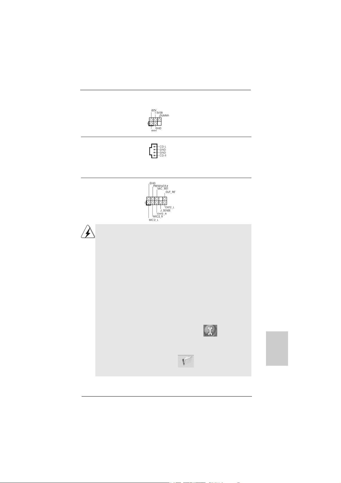
Infrared Module Header This header supports an
(5-pin IR1) optional wireless transmitting
(see p.2 No. 30) and receiving infrared module.
Internal Audio Connectors This connector allows you
(4-pin CD1) to receive stereo audio input
(CD1: see p.2 No. 34) from sound sources such as
a CD-ROM, D VD-ROM, TV
tuner card, or MPEG card.
Front Panel Audio Header This is an interface for the front
(9-pin HD_AUDIO1) panel audio cable that allows
(see p.2 No. 26) convenient connection and
control of audio devices.
CD1
1. High Definition Audio supports Jack Sensing, but the panel wire on
the hassis must support HDA to function correctly. Please follow the
instruction in our manual and chassis manual to install your system.
2. If you use AC’97 audio panel, please install it to the front panel audio
header as below:
A. Connect Mic_IN (MIC) to MIC2_L.
B. Connect Audio_R (RIN) to OUT2_R and Audio_L (LIN) to OUT2_L.
C. Connect Ground (GND) to Ground (GND).
D. MIC_RET and OUT_RET are for HD audio panel only. You don’t
need to connect them for AC’97 audio panel.
E. Enter BIOS Setup Utility. Enter Advanced Settings, and then select
Chipset Configuration. Set the Front Panel Control option from
[Auto] to [Enabled].
F. Enter Windows system. Click the icon on the lower right hand
taskbar to enter Realtek HD Audio Manager.
For Windows
®
2000 / XP / XP 64-bit OS:
Click “Audio I/O”, select “Connector Settings” , choose
“Disable front panel jack detection”, and save the change by
clicking “OK”.
For Windows
®
Vista
TM
/ Vista
TM
64-bit OS:
Click the right-top “Folder” icon , choose “Disable front
panel jack detection”, and save the change by clicking “OK”.
2424
2424
24
ASRock ALiveXFire-eSATA2 Motherboard
EnglishEnglish
EnglishEnglish
English
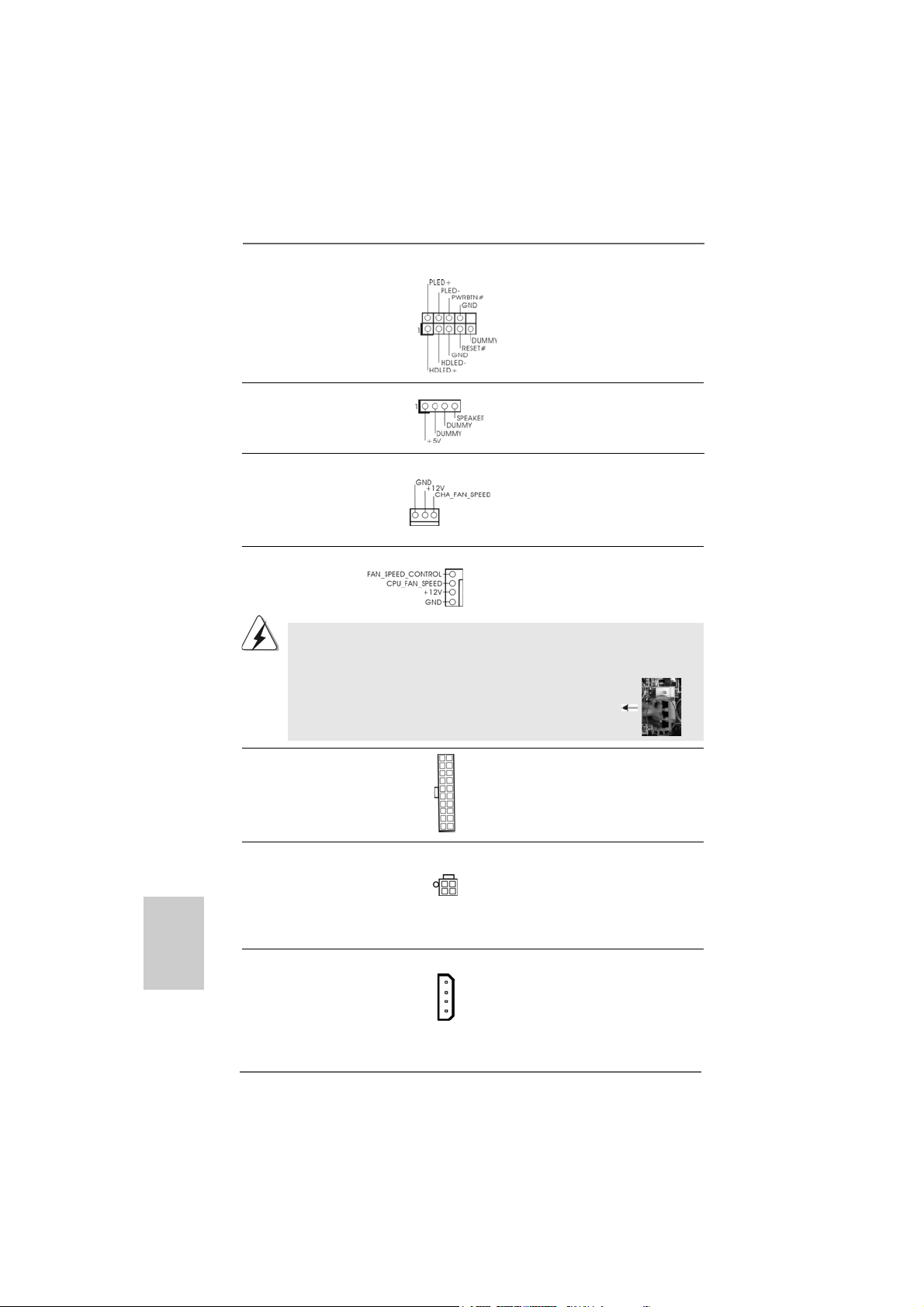
Chassis Speaker Header Please connect the chassis
(4-pin SPEAKER 1) speaker to this header.
(see p.2 No. 24)
Chassis Fan Connector Please connect a chassis fan
(3-pin CHA_FAN1) cable to this connector and
(see p.2 No. 22) match the black wire to the
ground pin.
CPU Fan Connector Please connect the CPU fan
(4-pin CPU_FAN1) cable to this connector and
(see p.2 No. 3) match the black wire to the
ground pin.
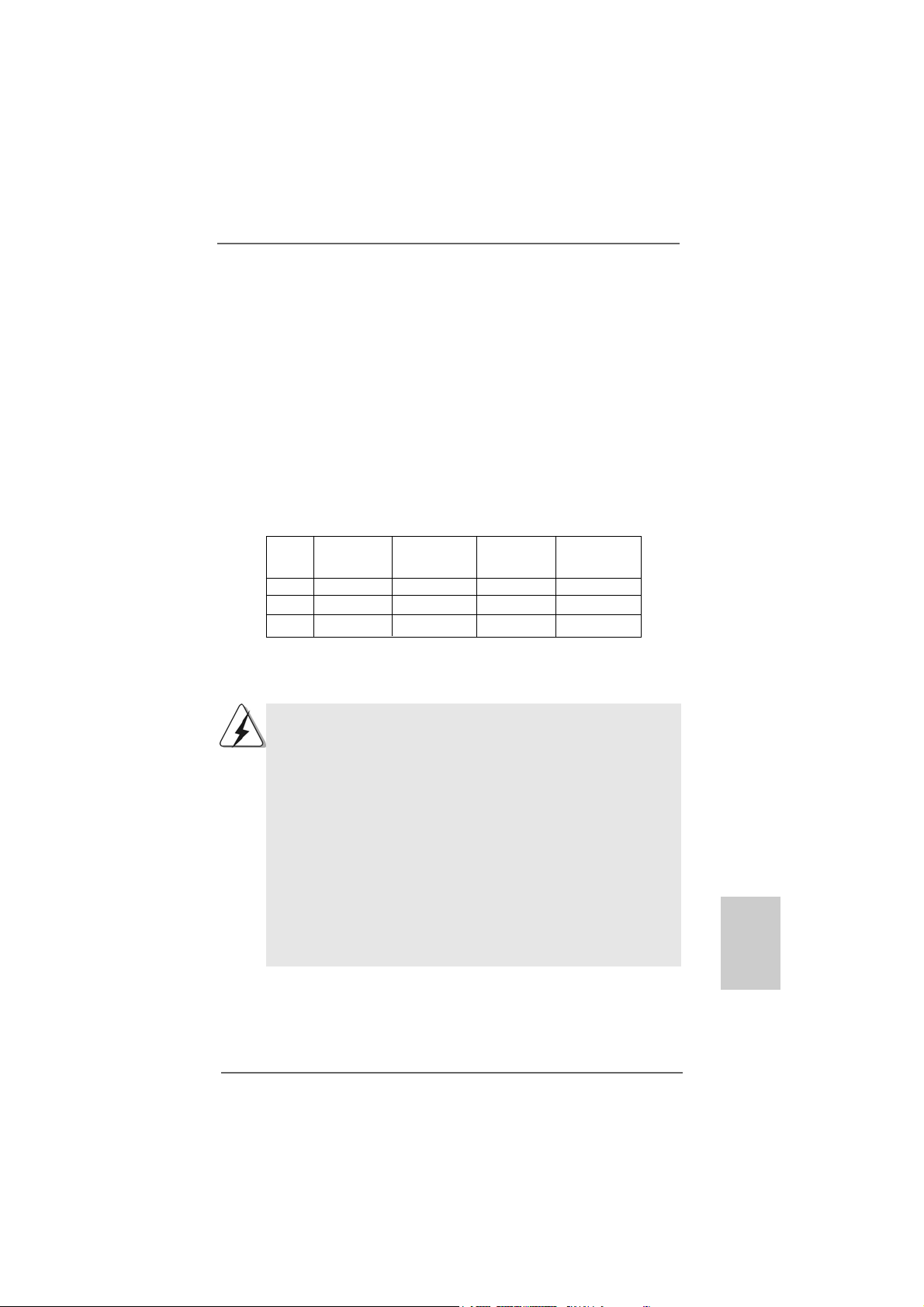
Though this motherboard provides 4-Pin CPU fan (Quiet Fan) support, the 3-Pin
CPU fan still can work successfully even without the fan speed control function.
If you plan to connect the 3-Pin CPU fan to the CPU fan connector on this
motherboard, please connect it to Pin 1-3.
3-Pin Fan Installation
Pin 1-3 Connected
ATX Power Connector Please connect an ATX power
(20-pin ATXPW R1) supply to this connector.
(see p.2 No. 4)
ATX 12V Power Connector Please note that it is necessary
(4-pin A TX12V1) to connect a power supply with
(see p.2 No. 2) ATX 12V plug to this connector.
Failing to do so will cause power
up failure.
SLI/XFIRE Power Connector It is not necessary to use this
(4-pin SLI/XFIRE_POWER1) connector, but please connect it
(see p.2 No. 33) with a hard disk power connecor
when two graphics cards are
plugged to this motherboard at
the same ti me.
4
3
2
1
SLI/XFIRE_POWER1
System Panel Hea der This header a ccommodate s
(9-pin PANEL1) several system front panel
(see p.2 No. 23) functions.

2525
2525
25
ASRock ALiveXFire-eSATA2 Motherboard
EnglishEnglish
EnglishEnglish
English
ation
C
B
A
HDMI_SPDIF Header HDMI_SPDIF header, providing
(3-pin HDMI_SPDIF1) SPDIF audio output to HDMI V GA
(see p.2 No. 28) card, allows the system to
connect HDMI Digital TV/
projector/LCD devices. Please
connect the HDMI_SPDIF
connector of HDMI VGA card to
this header.
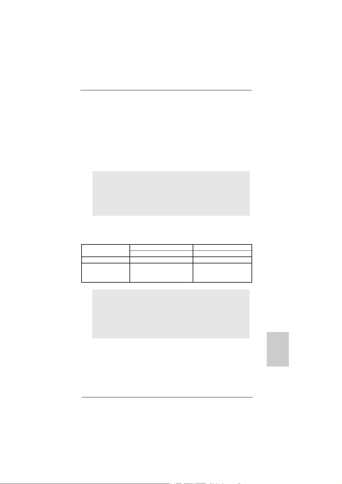
HDMI_SPDIF Cable Please connect the black end (A)
(Optional) of HDMI_SPDIF cable to the
HDMI_SPDIF header on the
motherboard. Then connect the
white end (B or C) of
HDMI_SPDIF cable to the
HDMI_SPDIF connector of HDMI
VGA card.
A. black end B. white end (2-pin) C. white end (3-pin)
USB Bracket This USB bracket can support 2
additional USB 2.0 ports besides
the I/O panel. Please connect
the blue connector on the cable
of this USB bracket to the USB
2.0 header (USB2_3, USB4_5,
USB6_7 or USB8_9) and fasten
the USB bracket to the chassis
with screws.

2626
2626
26
ASRock ALiveXFire-eSATA2 Motherboard
2.10 HDMI_SPDIF Header Connection Guide2.10 HDMI_SPDIF Header Connection Guide
2.10 HDMI_SPDIF Header Connection Guide2.10 HDMI_SPDIF Header Connection Guide
2.10 HDMI_SPDIF Header Connection Guide
HDMI (High-Definition Multi-media Interfa ce) is an all-digital audio/video specification,
which provides an interface between any compatible digital audio/video source,
such as a set-top box, DVD player, A/V receiver and a compatible digital audio or
video monitor, such as a digital television (DTV). A complete HDMI system requires a
HDMI VGA card and a HDMI ready motherboard with a HDMI_SPDIF header. This
motherboard is equipped with a HDMI_SPDIF header, which provides SPDIF audio
output to HDMI VGA card, allows the system to connect HDMI Digital TV/projector/
LCD devices. To use HDMI function on this motherboard, please carefully follow the
below steps.
•
Make sure to correctly connect the HDMI_SPDIF cable to the motherboard and the
HDMI VGA card according to the same pin definition. For the pin definition of
HDMI_SPDIF header and HDMI_SPDIF ca ble connectors, ple ase refer to page 25. For
the pin definition of HDMI_SPDIF connectors on HDMI VGA card, please refer to the
user manual of HDMI VGA card vendor. Incorrect connection may cause permanent
damage to this motherboard and the HDMI VGA card.
white end
(2-pin) (B)
white end
(3-pin) (C)
Please do not connect the white end of HDMI_SPDIF cable to the wrong connector
of HDMI VGA card or other VGA card. Otherwise, the motherboard and the
VGA card may be damaged. For example, this picture shows the wrong
example of connecting HDMI_SPDIF cable to the fan connector of PCI
Express VGA card. Please refer to the VGA card user manual for
connector usage in advance.
Step 4. Connect the HDMI output connector on HDMI VG A card to
HDMI device, such as HDTV. Please refer to the user manual
of HDTV and HDMI VGA card vendor for detailed connection
procedures.
Step 5. Install HDMI VGA card driver to your system.
Step 3. Connect the white end (B or C) of HDMI_SPDIF cable to the HDMI_SPDIF
connector of HDMI VGA card. (There are two white ends (2-pin and 3-pin)
on HDMI_SPDIF cable. Please choose the appropriate white end according
to the HDMI_SPDIF connector of the HDMI VGA card you install.
Step 1. Install the HDMI VGA card to the PCI Express Graphics slot on this
motherboard. For the proper installation of HDMI VGA card, please refer
to the installation guide on page 14 and page 15.
Step 2. Connect the black end (A) of HDMI_SPDIF cable to the
HDMI_SPDIF header (HDMI_SPDIF1, yellow , see page 2, No.
28) on the motherboard.
EnglishEnglish
EnglishEnglish
English
2727
2727
27
ASRock ALiveXFire-eSATA2 Motherboard
EnglishEnglish
EnglishEnglish
English
2.11 eSA2.11 eSA
2.11 eSA2.11 eSA
2.11 eSA
TT
TT
T
AII InterAII Inter
AII InterAII Inter
AII Inter
face Introductionface Introduction
face Introductionface Introduction
face Introduction
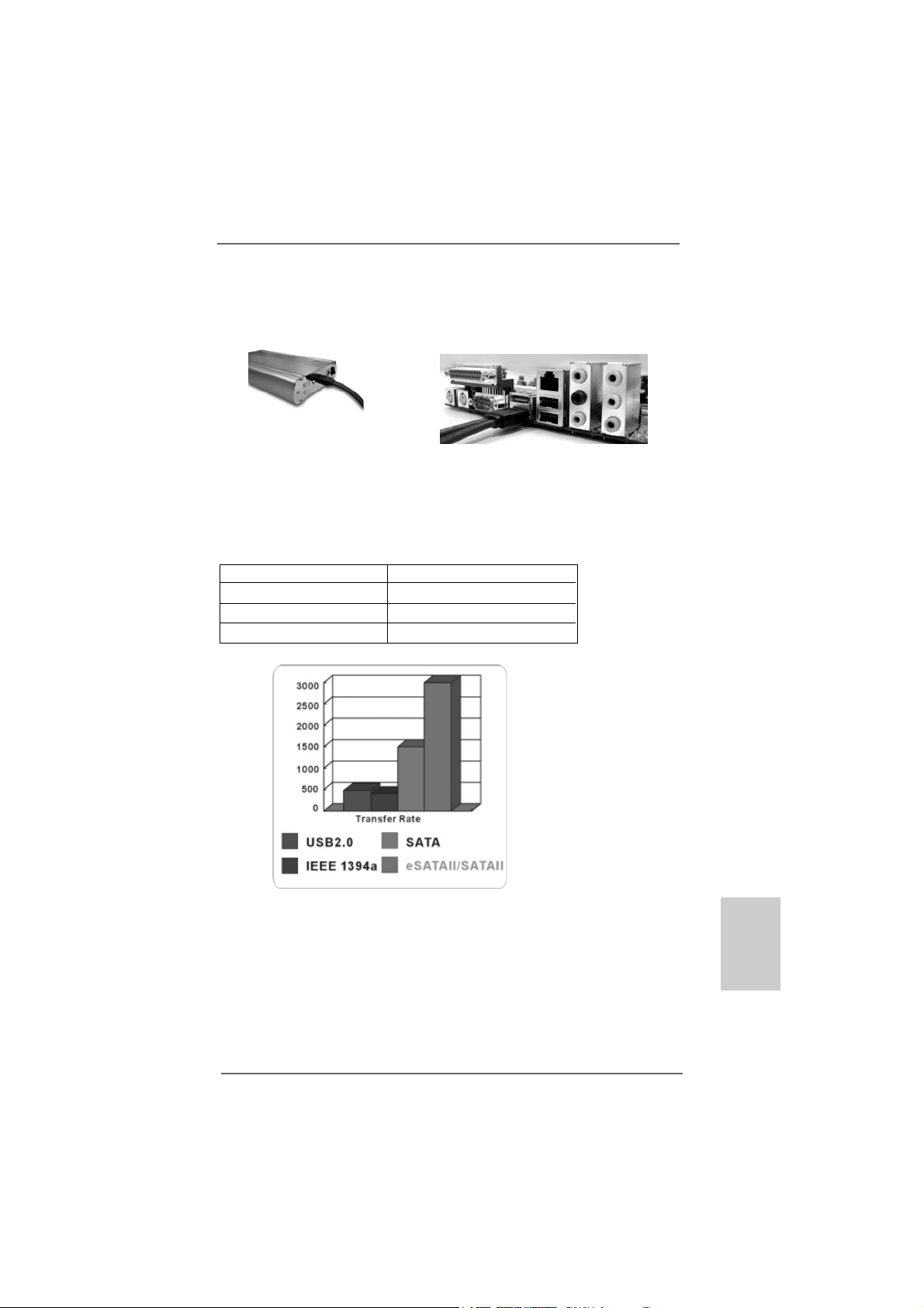
What is eSATAII?
This motherboard supports eSATAII interface, the external SATAII specification.
eSATAII allows you to enjoy the SATAII function provided by the I/O of your
computer, offering the high speed data transfer rate up to 3.0Gb/s, and the
convenient mobility like USB. eSATAII is equipped with Hot Plug capability that
enables you to exchange drives easily. For example, with eSATAII interface, you
may simply plug your eSATAII hard disk to the eSATAII ports instead of opening
your chassis to exchange your SATAII hard disk. Currently, on the market, the
data transfer rate of USB 2.0 is up to 480Mb/s, and for IEEE 1394 is up to
400Mb/s. However, eSATAII provides the data transfer rate up to 3000Mb/s,
which is much higher than USB 2.0 and IEEE 1394, and still keeps the conve-
nience of Hot Plug feature. Therefore, on the basis of the advantageous transfer
speed and the facilitating mobile capability, in the near future, eSATAII will replace
USB 2.0 and IEEE 1394 to be a trend for external interface.
SATAII_RED (PORT 1)
and SA TAII_ORANGE (PORT 2)
eSAT AII_TOP and
eSATAII_BOTTOM
NOTE:
1. If you set “SATA Operation Mode” option in BIOS setup to AHCI or RAID mode, Hot
Plug function is supported with eSATAII devices. Therefore, you can insert or
remove your eSATAII devices to the eSATAII ports while the system is power-on and
in working condition.
2. If you set “SATA Operation Mode” option in BIOS setup to non-RAID mode, Hot
Plug function is not supported with eSATAII devices. If you still want to use eSATAII
function in non-RAID mode, please insert or remove your eSATAII devices to the
eSATAII ports only when the system is power-off.
3. Please refer to page 32 to 37 for detailed information of RAID mode, non-RAID
mode, and AHCI mode.
How to install eSATAII?
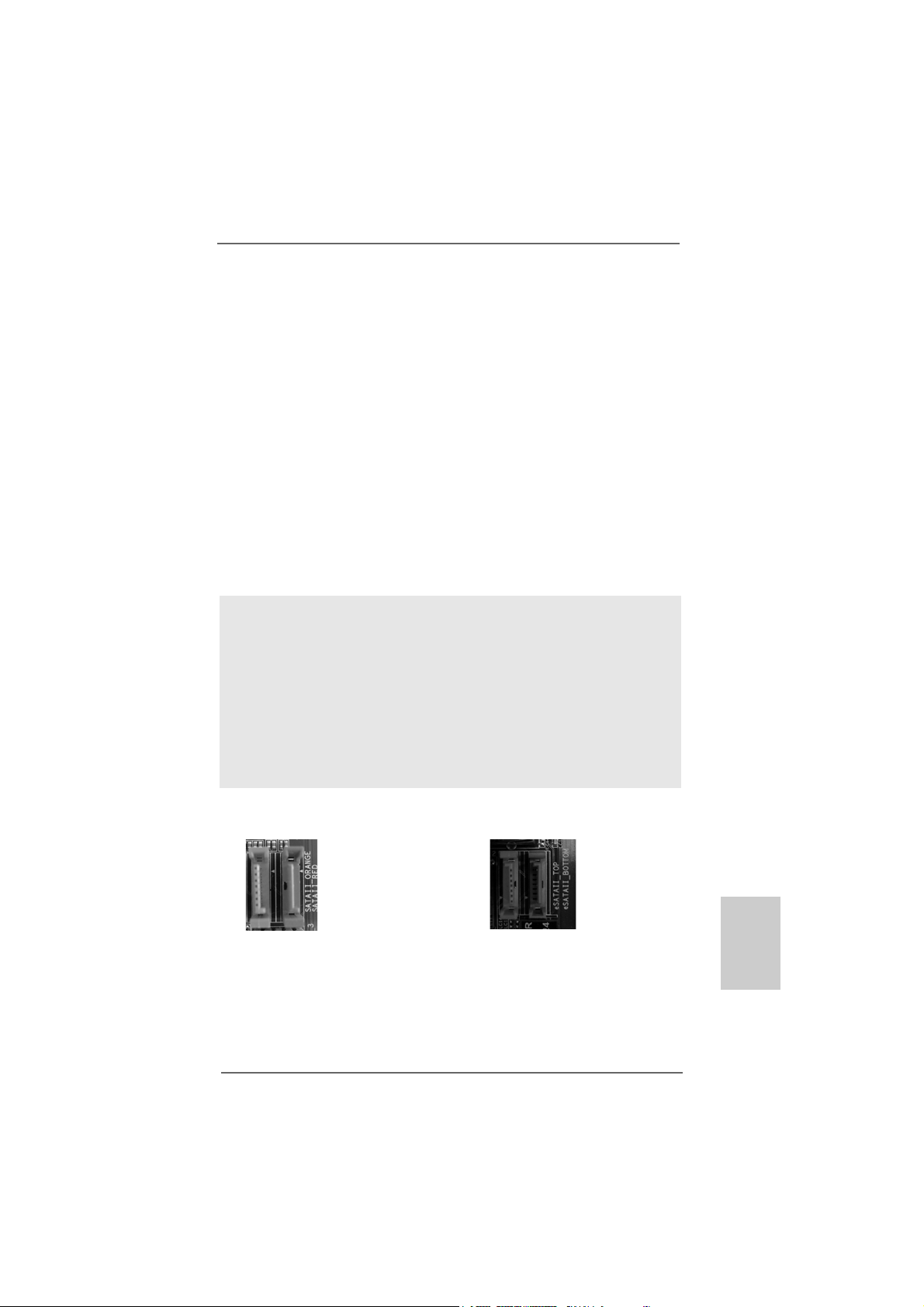
1. If you just plan to install one eSATAII device to this motherboard, it is recom-
mended to enable the bottom eSATAII port of the I/O shield. In order to enable
the bottom eSATAII port of the I/O shield, you need to connect the red SATAII
connector (SATAII_RED (PORT 1); see p.2 No.15) and the red eSATAII
connector (eSATAII_BOTTOM; see p.2 No.36) with a SAT A data cable f irst. Then
the bottom eSATAII port of the I/O shield is enabled.
2828
2828
28
ASRock ALiveXFire-eSATA2 Motherboard
EnglishEnglish
EnglishEnglish
English
2. If you plan to install two eSATAII devices to this motherboard, you need to
enable both the top and the bottom eSATAII ports of the I/O shield. In order to
enable the top and the bottom eSATAII ports of the I/O shield, you have to
connect the red SATAII connector (SATAII_RED (PORT 1); see p.2 No.15) and
the red eSATAII connector (eSATAII_BOTTOM; see p.2 No.36) with a SAT A data
cable first, and then connect the ora nge SAT AII connector (SA TAII_ORANGE
(PORT 2); see p.2 No.14) a nd the ora nge eSA TAII connector (eSATAII_TOP; see
p.2 No.35) with a nother SATA data cable. After that, both the top a nd the bottom
eSATAII ports of the I/O shield are enabled.
Please make sure to correctly connect the SATAII and eSATAII connectors
with corresponding color so that the eSATAII function will work successfully.
Connect the SATA
data cables to both
red SATAII connector
(SATAII_RED (PORT 1))
and orange SATAII
connector (SATAII_
ORANGE (PORT 2))
Connect the SATA
data cables to both
red eSATAII connector
(eSATAII_BOTTOM)
and orange eSATAII
connector (eSATAII_TOP)
Connect the SATA
data cable to the red
SATAII connector
(SATAII_RED (PORT 1))
Connect the SATA
data cable to the red
eSATAII connector
(eSATAII_BOTTOM)
2929
2929
29
ASRock ALiveXFire-eSATA2 Motherboard
EnglishEnglish
EnglishEnglish
English
Comparison between eSATAII and other devices
IEEE 1394 400Mb/s
USB 2.0 480Mb/s
SATA 1.5Gb/s (1500Mb/s)
eSATAII/SATAII 3.0Gb/s (3000Mb/s)
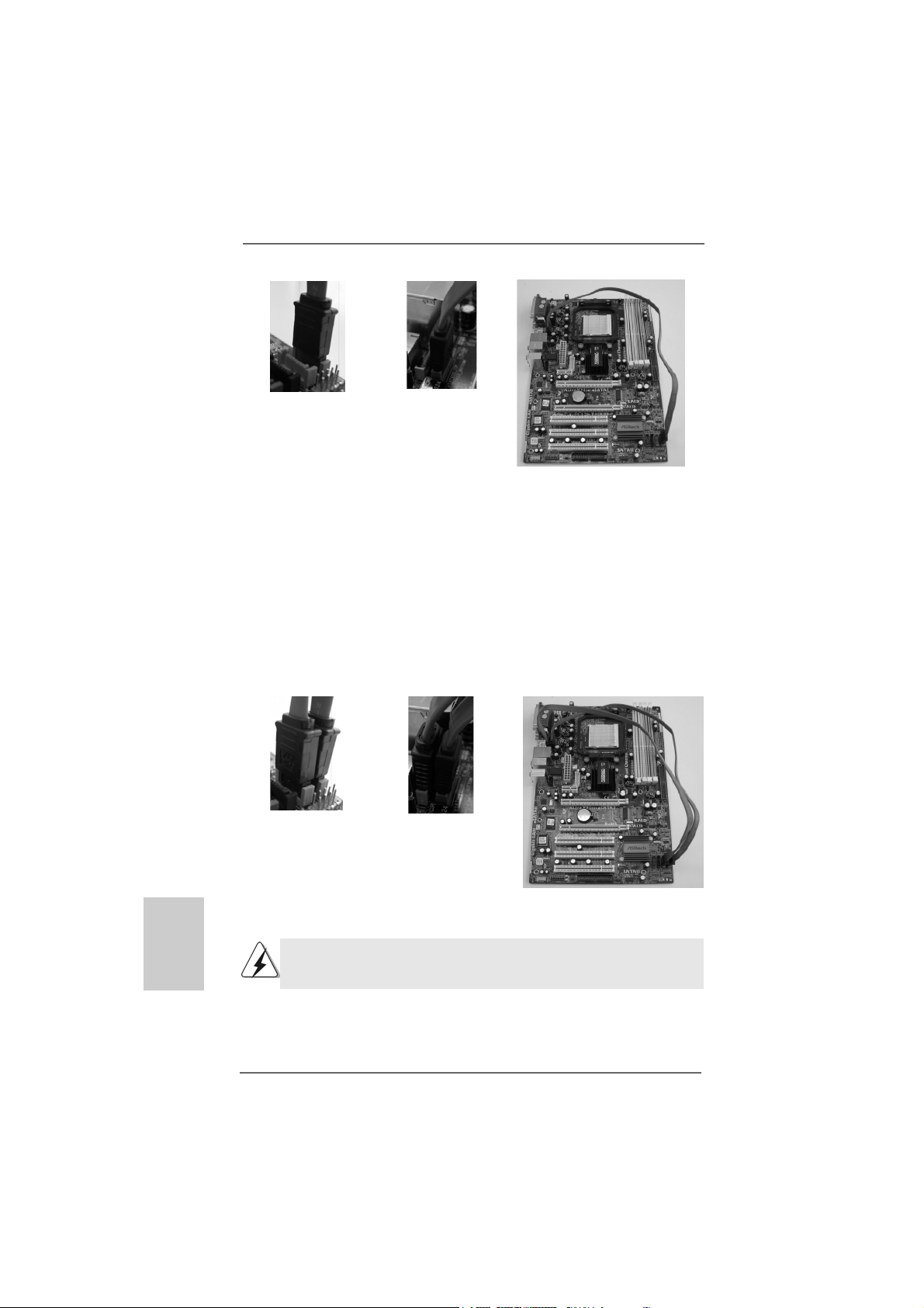
Connect one end of the eSATAII
device cable to eSATAII device
Connect the other end of the eSATAII
device cable to eSATAII port of the I/O
shield
3. Use the eSATAII device cable to connect eSATAII device and the eSATAII port
of the I/O shield according to the eSATAII connector that you connect the
SATA data cable.
3030
3030
30
ASRock ALiveXFire-eSATA2 Motherboard
EnglishEnglish
EnglishEnglish
English
2.122.12
2.122.12
2.12
SASA
SASA
SA
TT
TT
T
AII Hard Disk Setup GuideAII Hard Disk Setup Guide
AII Hard Disk Setup GuideAII Hard Disk Setup Guide
AII Hard Disk Setup Guide
Before installing SATAII hard disk to your computer, please carefully read below
SATAII hard disk setup guide. Some default setting of SATAII hard disks may not be
at SATAII mode, which operate with the best performance. In order to enable SATAII
function, please follow the below instruction with different vendors to correctly
adjust your SA TAII hard disk to SA TAII mode in advance; otherwise, your SAT AII hard
disk may fail to run at SATAII mode.
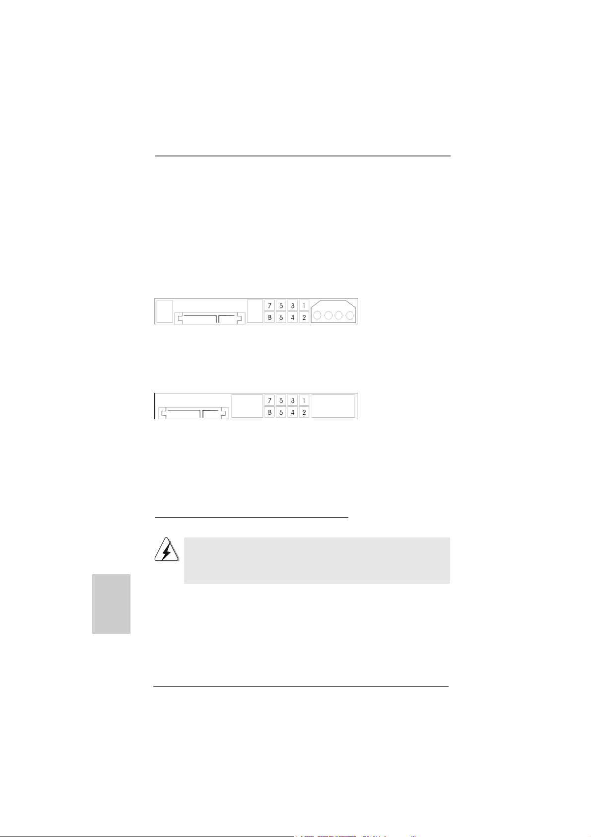
Western Digital
If pin 5 and pin 6 are shorted, SATA 1.5Gb/s will be enabled.
On the other hand, if you want to enable SATAII 3.0Gb/s, please remove the jumpers
from pin 5 and pin 6.
SAMSUNG
If pin 3 and pin 4 are shorted, SATA 1.5Gb/s will be enabled.
On the other hand, if you want to enable SATAII 3.0Gb/s, please remove the jumpers
from pin 3 and pin 4.
HITACHI
Please use the Feature Tool, a DOS-bootable tool, for changing various ATA features.
Please visit HITACHI’s website for details:
http://www.hitachigst.com/hdd/support/download.htm
The above examples are just for your reference. For different SATAII hard
disk products of different vendors, the jumper pin setting methods may not
be the same. Please visit the vendors’ website for the updates.
 Loading...