


Copyright Notice:
No part of this installation guide may be reproduced, transcribed, transmitted, or translated in any language, in any form or by any means, except duplication of documentation by the purchaser for backup purpose, without written consent of ASRock Inc.
Products and corporate names appearing in this guide may or may not be registered trademarks or copyrights of their respective companies, and are used only for identification or explanation and to the owners’ benefit, without intent to infringe.
Disclaimer:
Specifications and information contained in this guide are furnished for informational use only and subject to change without notice, and should not be constructed as a commitment by ASRock. ASRock assumes no responsibility for any errors or omissions that may appear in this guide.
With respect to the contents of this guide, ASRock does not provide warranty of any kind, either expressed or implied, including but not limited to the implied warranties or conditions of merchantability or fitness for a particular purpose. In no event shall ASRock, its directors, officers, employees, or agents be liable for any indirect, special, incidental, or consequential damages (including damages for loss of profits, loss of business, loss of data, interruption of business and the like), even if ASRock has been advised of the possibility of such damages arising from any defect or error in the guide or product.
This device complies with Part 15 of the FCC Rules. Operation is subject to the following two conditions:
(1)this device may not cause harmful interference, and
(2)this device must accept any interference received, including interference that may cause undesired operation.
CALIFORNIA, USA ONLY
The Lithium battery adopted on this motherboard contains Perchlorate, a toxic substance controlled in Perchlorate Best Management Practices (BMP) regulations passed by the California Legislature. When you discard the Lithium battery in California, USA, please follow the related regulations in advance.
“Perchlorate Material-special handling may apply, see www.dtsc.ca.gov/hazardouswaste/perchlorate”
ASRock Website: http://www.asrock.com
Published June 2013
Copyright©2013 ASRock INC. All rights reserved.
1
English
ASRock 960GC-GS FX Motherboard

English
Motherboard Layout |
|
|
|
|
|
|
|
|
|
|
|
||||||
|
|
1 |
|
|
|
|
|
|
|
|
|
2 |
3 |
|
4 |
|
|
Keyboard PS2 |
Mouse |
PS2 |
|
|
|
|
|
|
|
|
|
|
|
|
|
CPU_FAN1 |
|
B: USB3 |
|
|
|
|
|
|
+AM2/AM3/AM3 |
|
|
pin-240bit,(641 |
pin-240bit,(64A1module) |
pin-240bit,(642 |
pin-240bit,(64B1module) |
|
ATXPWR1 |
|
|
COM1 |
|
ATX12V1 |
|
|
|
|
|
|
|
|
|
|
|
|
|
|
5 |
VGA1 |
|
|
|
|
|
|
|
|
|
|
FSB800 |
FSB800 |
|
|
|
||
|
|
|
|
|
|
|
|
|
|
|
module) |
|
module) |
|
|
|
|
USB 2.0 |
|
|
|
|
|
|
|
|
|
|
|
|
|
|
|
|
|
T: USB2 |
|
|
|
|
|
|
|
|
|
|
|
|
|
|
|
|
|
USB 2.0 |
Top: |
|
|
|
|
|
|
|
|
DDRII_ |
DDR3_ |
DDRII_ |
DDR3_ |
|
|
|
|
T: USB0 |
|
|
|
|
|
|
|
|
|
|
|
|
|
IDE1 |
|
||
|
|
RJ-45 |
|
|
|
|
|
|
|
|
|
|
|
|
|
|
|
B: USB1 |
LAN |
|
|
|
|
|
|
|
|
|
|
|
|
|
|
||
27 |
|
|
|
|
|
|
|
|
|
|
|
|
|
|
|
|
|
MI Bottom: CI N |
FRON Center: T |
LINE Top: IN |
|
|
|
AMD |
|
|
|
|
|
|
|
|
|
|
6 |
|
|
|
|
|
|
|
|
|
|
|
|
|
|
|
|
||
|
|
|
|
|
|
|
PWR_FAN1 |
|
|
|
|
|
|
|
|
||
|
|
|
|
|
|
760G |
|
|
|
|
|
CLRCMOS1 |
|
|
|
|
|
|
|
AUDIO |
|
|
|
Chipset |
|
|
|
|
1 |
|
|
|
|
|
|
|
|
CODEC |
|
|
|
|
|
|
|
|
|
|
|
|
|
|
|
|
|
|
|
|
PCIE1 |
|
|
|
|
|
|
|
|
|
|
|
|
|
|
RoHS |
|
960GC-GS FX |
|
|
|
|
|
|
|
|
|
|
|||
|
|
|
|
|
|
|
|
|
|
|
|
|
|
|
|
|
7 |
|
|
|
|
|
|
PCIE2 |
|
|
|
|
|
|
|
|
|
|
|
|
|
Super |
XFast LAN |
XFast USB XFast RAM |
|
|
|
|
|
AMD |
|
|
|||||
|
|
I/O |
CMOS |
|
|
|
|
|
|||||||||
|
|
|
|
|
|
|
|
|
|
|
|
|
|
||||
|
|
|
|
|
|
|
|
|
|
|
SB710 |
|
|
||||
|
|
|
|
|
|
|
|
BATTERY |
|
|
|
|
|||||
|
|
|
|
|
|
PCI1 |
|
|
|
|
|
|
Chipset |
|
|
||
|
|
|
|
|
|
|
|
|
|
|
|
|
CHA_FAN1 |
|
|||
26 |
|
|
|
|
|
|
|
|
|
|
|
|
|
|
|
|
8 |
|
|
|
|
|
|
|
|
|
|
16Mb |
|
|
|
|
|||
|
|
|
|
|
|
|
|
|
|
|
|
|
|
|
|||
|
|
CD1 |
|
|
|
|
|
|
|
BIOS |
|
|
|
|
|
|
|
|
|
|
|
|
|
PCI2 |
|
|
|
|
|
|
|
|
SATAII_6 (PORT 5) |
|
|
|
HD_AUDIO1 |
|
|
|
|
|
USB6_7 |
USB8_9 |
|
|
|
|
|
|
|
||
|
|
|
|
|
|
|
|
SATAII_2 (PORT 1) |
|
SATAII_4 (PORT 3) |
|
|
9 |
||||
25 |
1 |
|
|
|
|
|
|
|
|
|
|
|
|
|
|
|
|
|
|
CI1 |
|
|
|
|
USB4_5 |
|
|
|
|
|
|
|
|
|
|
24 |
1 |
|
|
|
FLOPPY1 |
|
|
|
|
|
|
|
|
|
SATAII_5 (PORT 4) |
|
|
|
1 |
|
|
|
|
PLED PWRBTN |
|
|
|
|
|
|
|
|
|
10 |
|
|
SPDIF_OUT1 |
|
|
|
|
|
|
|
|
SATAII_1 (PORT 0) |
|
SATAII_3 (PORT 2) |
|
|
|
||
|
|
|
|
IR1 |
|
|
|
|
|
|
|
|
SPEAKER1 |
|
|
|
|
1 |
|
|
1 |
|
|
1 |
HDLED RESET |
1 |
1 |
1 |
|
1 |
|
|
|
|
|
|
|
LPT1 |
|
|
|
|
|
|
|
|
|
|
|
||||
|
|
|
|
|
PANEL1 |
|
|
|
|
|
|
|
|
|
|
||
|
|
23 |
22 |
21 |
|
20 |
19 |
18 |
17 16 15 |
|
14 |
13 |
12 |
11 |
|
|
|
1 |
ATX 12V Power Connector (ATX12V1) |
14 |
SATA2 Connector (SATAII_1 (PORT 0)) |
2 |
2 x 240-pin DDR2 DIMM Slots |
15 |
SATA2 Connector (SATAII_2 (PORT 1)) |
|
(Dual Channel: DDRII_1, DDRII_2) |
16 |
USB 2.0 Header (USB8_9) |
3 |
2 x 240-pin DDR3 DIMM Slots |
17 |
USB 2.0 Header (USB6_7) |
|
(Dual Channel: DDR3_A1, DDR3_B1) |
18 |
USB 2.0 Header (USB4_5) |
4 |
CPU Fan Connector (CPU_FAN1) |
19 |
System Panel Header (PANEL1) |
5 |
ATX Power Connector (ATXPWR1) |
20 |
Floppy Connector (FLOPPY1) |
6 |
Primary IDE Connector (IDE1) |
21 |
Infrared Module Header (IR1) |
7 |
Clear CMOS Jumper (CLRCMOS1) |
22 |
Chassis Intrusion Header (CI1) |
8 |
Chassis Fan Connector (CHA_FAN1) |
23 |
Print Port Header (LPT1) |
9 |
SATA2 Connector (SATAII_6 (PORT 5)) |
24 |
SPDIF Out Connector (SPDIF_OUT1) |
10 |
SATA2 Connector (SATAII_5 (PORT 4)) |
25 |
Front Panel Audio Header (HD_AUDIO1) |
11 |
SATA2 Connector (SATAII_4 (PORT 3)) |
26 |
Internal Audio Connector (CD1) |
12 |
SATA2 Connector (SATAII_3 (PORT 2)) |
27 |
Power Fan Connector (PWR_FAN1) |
13 |
Chassis Speaker Header (SPEAKER1) |
|
|
2
ASRock 960GC-GS FX Motherboard
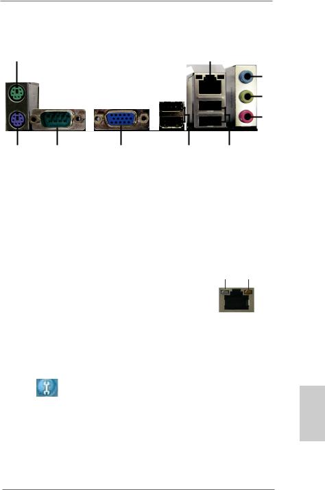
I/O Panel
1 |
2 |
|
|
|
|
3
4
5
10 |
9 |
8 |
|
7 |
6 |
1 |
PS/2 Mouse Port (Green) |
|
6 |
USB 2.0 |
Ports (USB01) |
* 2 |
LAN RJ-45 Port |
|
7 |
USB 2.0 |
Ports (USB23) |
3 |
Line In (Light Blue) |
|
8 |
D-Sub Port |
|
** 4 |
Front Speaker (Lime) |
|
9 |
COM Port |
|
5 |
Microphone (Pink) |
|
10 |
PS/2 Keyboard Port (Purple) |
|
*There are two LED next to the LAN port. Please refer to the table below for the LAN port LED indications.
|
LAN Port LED Indications |
ACT/LINK SPEED |
|||||
Activity/Link LED |
|
|
SPEED LED |
||||
|
|
LED |
LED |
||||
Status |
Description |
|
Status |
|
Description |
|
|
Off |
No Link |
|
Off |
|
10Mbps connection |
|
|
Blinking |
Data Activity |
|
Orange |
|
100Mbps connection |
|
|
On |
Link |
|
Green |
|
1Gbps connection |
LAN Port |
|
|
|
|
|
|
|
||
** To enable Multi-Streaming function, you need to connect a front panel audio cable to the front panel audio header. Please refer to below steps for the software setting of Multi-Streaming. For Windows® XP:
After restarting your computer, you will find “Mixer” tool on your system. Please select “Mixer
ToolBox” |
, click “Enable playback multi-streaming”, and click “ok”. Choose “2CH” or |
|
English |
“4CH” and then you are allowed to select “Realtek HDA Primary output” to use Rear Speaker and Front Speaker, or select “Realtek HDA Audio 2nd output” to use front panel audio. Then reboot your system.
For Windows® 8 / 7 / VistaTM:
After restarting your computer, please double-click “Realtek HD Audio Manager” on the system tray. Set “Speaker Configuration” to “Quadraphonic” or “Stereo”. Click “Device advanced settings”, choose “Make front and rear output devices playbacks two different audio streams simultaneously”, and click “ok”. Then reboot your system.
3
ASRock 960GC-GS FX Motherboard

1. Introduction
Thank you for purchasing ASRock 960GC-GS FX motherboard, a reliable motherboard produced under ASRock’s consistently stringent quality control. It delivers excellent performance with robust design conforming to ASRock’s commitment to quality and endurance.
This Quick Installation Guide contains introduction of the motherboard and step-by- step installation guide. More detailed information of the motherboard can be found in the user manual presented in the Support CD.
Because the motherboard specifications and the BIOS software might be updated, the content of this manual will be subject to change without notice. In case any modifications of this manual occur, the updated version will be available on ASRock website without further notice. You may find the latest VGA cards and CPU support lists on ASRock website as well. ASRock website http://www.asrock.com
If you require technical support related to this motherboard, please visit our website for specific information about the model you are using. www.asrock.com/support/index.asp
1.1 Package Contents
ASRock 960GC-GS FX Motherboard (Micro ATX Form Factor)
ASRock 960GC-GS FX Quick Installation Guide
ASRock 960GC-GS FX Support CD
2 x Serial ATA (SATA) Data Cables (Optional)
1 x I/O Panel Shield
ASRock Reminds You...
To get better performance in Windows® 8 / 8 64-bit / 7 / 7 64-bit / VistaTM / VistaTM 64-bit, it is recommended to set the BIOS option in Storage
Configuration to AHCI mode. For the BIOS setup, please refer to the “User
Manual” in our support CD for details.
English
4
ASRock 960GC-GS FX Motherboard

1.2 Specifications
Platform |
- Micro ATX Form Factor |
CPU |
- Support for Socket AM3+ processors (see CAUTION 1) |
|
- Support for Socket AM3 processors: AMD PhenomTM II X6 / |
|
X4 / X3 / X2 (except 920 / 940) / Athlon II X4 / X3 / X2 / |
|
Sempron processors |
|
- Support for Socket AM2+ / AM2 processors: AMD PhenomTM |
|
FX / Phenom / Athlon 64 FX / Athlon 64 X2 Dual-Core / |
|
Athlon X2 Dual-Core / Athlon 64 / Sempron processor |
|
- Supports 8-Core CPU |
|
- Supports AMD OverDriveTM with ACC feature (Advanced |
|
Clock Calibration) |
|
- Supports AMD’s Cool ‘n’ QuietTM Technology |
|
- FSB 2600 MHz (5.2 GT/s) |
|
- Supports Untied Overclocking Technology |
|
- Supports Hyper-Transport 3.0 (HT 3.0) Technology |
Chipset |
- Northbridge: AMD 760G |
|
- Southbridge: AMD SB710 |
Memory |
- Dual Channel DDR3/DDR2 Memory Technology |
|
- 2 x DDR3 DIMM slots |
|
- Support DDR3 1866(OC)/1600(OC)/1333/1066 non-ECC, |
|
un-buffered memory (see CAUTION 2) |
|
- Max. capacity of system memory: 16GB (see CAUTION 3) |
|
- 2 x DDR2 DIMM slots |
|
- Supports DDR2 1066/800/667/533 non-ECC, un-buffered |
|
memory |
|
- Max. capacity of system memory: 8GB (see CAUTION 3) |
Expansion Slot |
- 1 x PCI Express 2.0 x16 slot (PCIE2 @ x16 mode) |
|
- 1 x PCI Express 2.0 x1 slot |
|
- 2 x PCI slots |
Graphics |
- Integrated AMD Radeon 3000 graphics |
|
- DX10 class iGPU, Pixel Shader 4.0 |
|
- Max. shared memory 512MB |
|
- Supports D-Sub with max. resolution up to 2048x1536 @ |
|
60Hz |
Audio |
- 5.1 CH HD Audio (Realtek ALC662 Audio Codec) |
LAN |
- PCIE x1 Gigabit LAN 10/100/1000 Mb/s |
|
- Realtek RTL8111G |
|
- Supports Wake-On-LAN |
|
|
English
5
ASRock 960GC-GS FX Motherboard

English
|
|
|
- Supports LAN Cable Detection |
|
- Supports Energy Efficient Ethernet 802.3az |
|
- Supports PXE |
Rear Panel I/O |
I/O Panel |
|
- 1 x PS/2 Mouse Port |
|
- 1 x PS/2 Keyboard Port |
|
- 1 x Serial Port: COM1 |
|
- 1 x D-Sub Port |
|
- 4 x USB 2.0 Ports |
|
- 1 x RJ-45 LAN Port with LED (ACT/LINK LED and SPEED |
|
LED) |
|
- HD Audio Jack: Line in / Front Speaker / Microphone |
Storage |
- 6 x SATA2 3.0 Gb/s connectors, support RAID (RAID 0, |
|
RAID 1, RAID 10 and JBOD), NCQ, AHCI and Hot Plug |
Connector |
- 1 x ATA 133 IDE connector (supports 2 x IDE devices) |
|
- 1 x Floppy connector |
|
- 1 x IR header |
|
- 1 x Print Port header |
|
- 1 x Chassis Intrusion header |
|
- 1 x CPU Fan connector (4-pin) |
|
- 1 x Chassis Fan connector (3-pin) |
|
- 1 x Power Fan connector (3-pin) |
|
- 1 x 24 pin ATX power connector |
|
- 1 x 4 pin 12V power connector |
|
- 1 x CD In header |
|
- 1 x Front panel audio connector |
|
- 1 x SPDIF Out connector |
|
- 3 x USB 2.0 headers (support 6 USB 2.0 ports) |
BIOS Feature |
- 16Mb AMI Legal BIOS |
|
- Supports “Plug and Play” |
|
- ACPI 1.1 Compliance Wake Up Events |
|
- Supports jumperfree |
|
- SMBIOS 2.3.1 Support |
|
- CPU, VCCM, NB Voltage Multi-adjustment |
Support CD |
- Drivers, Utilities, AntiVirus Software (Trial Version), |
|
CyberLink MediaEspresso 6.5 Trial, Google Chrome |
|
Browser and Toolbar |
Hardware |
- CPU/Chassis Temperature Sensing |
Monitor |
- CPU/Chassis/Power Fan Tachometer |
|
- CPU Quiet Fan |
|
- CPU/Chassis/Power Fan Multi-Speed Control |
|
|
6
ASRock 960GC-GS FX Motherboard

|
- CASE OPEN detection |
|
- Voltage Monitoring: +12V, +5V, +3.3V, Vcore |
OS |
- Microsoft® Windows® 8 / 8 64-bit / 7 / 7 64-bit / VistaTM / |
|
VistaTM 64-bit / XP / XP Media Center / XP 64-bit compliant |
Certifications |
- FCC, CE, WHQL |
-ErP/EuP Ready (ErP/EuP ready power supply is required)
*For detailed product information, please visit our website: http://www.asrock.com
English
7
ASRock 960GC-GS FX Motherboard

WARNING
Please realize that there is a certain risk involved with overclocking, including adjusting the setting in the BIOS, applying Untied Overclocking Technology, or using third-party overclocking tools. Overclocking may affect your system’s stability, or even cause damage to the components and devices of your system. It should be done at your own risk and expense. We are not responsible for possible damage caused by overclocking.
CAUTION!
1.This motherboard supports CPU up to 95W. Please refer to our website for CPU support list.
ASRock website: http://www.asrock.com
2.Whether 1866/1600MHz memory speed is supported depends on the AM3/AM3+ CPU you adopt. If you want to adopt DDR3 1866/1600 memory module on this motherboard, please refer to the memory support list on our website for the compatible memory modules.
ASRock website: http://www.asrock.com
3.Due to the operating system limitation, the actual memory size may be less than 4GB for the reservation for system usage under Windows® 8 / 7 / VistaTM / XP. For Windows® 64-bit OS with 64-bit CPU, there is no such limitation.
English
8
ASRock 960GC-GS FX Motherboard

1.3 Unique Features
ASRock OC Tuner
ASRock OC Tuner is a user-friendly overclocking tool which allows you to surveil your system by hardware monitor function and overclock your hardware devices to get the best system performance under Windows® environment. Please visit our website for the operation procedures of ASRock OC Tuner.
ASRock Intelligent Energy Saver
Featuring an advanced proprietary hardware and software design, Intelligent Energy Saver is a revolutionary technology that delivers unparalleled power savings. The voltage regulator can reduce the number of output phases to improve efficiency when the CPU cores are idle. In other words, it is able to provide exceptional power saving and improve power efficiency without sacrificing computing performance. To use Intelligent Energy
Saver function, please enable Cool ‘n’ Quiet option in the BIOS setup in advance. Please visit our website for the operation procedures of Intelligent Energy Saver.
ASRock Instant Boot
ASRock Instant Boot allows you to turn on your PC in just a few seconds, provides a much more efficient way to save energy, time, money, and improves system running speed for your system. It leverages the S3 and S4 ACPI features which normally enable the Sleep/Standby and Hibernation modes in Windows® to shorten boot up time. By calling S3 and S4 at specific timing during the shutdown and startup process, Instant Boot allows you to enter your Windows® desktop in a few seconds.
ASRock Instant Flash
ASRock Instant Flash is a BIOS flash utility embedded in Flash
ROM. This convenient BIOS update tool allows you to update system BIOS without entering operating systems first like MS-
DOS or Windows®. With this utility, you can press the <F6> key during the POST or the <F2> key to enter into the BIOS setup menu to access ASRock Instant Flash. Just launch this tool and save the new BIOS file to your USB flash drive, floppy disk or hard drive, then you can update your BIOS only in a few clicks without preparing an additional floppy diskette or other
English
9
ASRock 960GC-GS FX Motherboard

English
10
complicated flash utility. Please be noted that the USB flash drive or hard drive must use FAT32/16/12 file system.
ASRock OC DNA
The software name itself – OC DNA literally tells you what it is capable of. OC DNA, an exclusive utility developed by ASRock, provides a convenient way for the user to record the OC settings and share with others. It helps you to save your overclocking record under the operating system and simplifies the complicated recording process of overclocking settings. With OC DNA, you can save your OC settings as a profile and share with your friends! Your friends then can load the OC profile to their own system to get the same OC settings as yours! Please be noticed that the OC profile can only be shared and worked on the same motherboard.
ASRock APP Charger
If you desire a faster, less restricted way of charging your Apple devices, such as iPhone/iPad/iPod Touch, ASRock has prepared a wonderful solution for you - ASRock APP Charger. Simply install the APP Charger driver, it makes your iPhone charge much quickly from your computer and up to 40% faster than before. ASRock APP Charger allows you to quickly charge many Apple devices simultaneously and even supports continuous charging when your PC enters into Standby mode (S1), Suspend to RAM (S3), hibernation mode (S4) or power off (S5). With APP Charger driver installed, you can easily enjoy the marvelous charging experience.
ASRock XFast USB
ASRock XFast USB can boost USB storage device performance. The performance may depend on the properties of the device.
ASRock XFast LAN
ASRock XFast LAN provides a faster internet access, which includes the benefits listed below. LAN Application Prioritization: You can configure your application’s priority ideally and/or add new programs. Lower Latency in Game: After setting online game’s priority higher, it can lower the latency in games. Traffic
Shaping: You can watch Youtube HD videos and download
ASRock 960GC-GS FX Motherboard
simultaneously. Real-Time Analysis of Your Data: With the status window, you can easily recognize which data streams you are transferring currently.
ASRock XFast RAM
ASRock XFast RAM fully utilizes the memory space that cannot be used under Windows® OS 32-bit CPU. ASRock XFast RAM shortens the loading time of previously visited websites, making web surfing faster than ever. And it also boosts the speed of
Adobe Photoshop 5 times faster. Another advantage of ASRock XFast RAM is that it reduces the frequency of accessing your SSDs or HDDs in order to extend their lifespan.
ASRock X-Boost
ASRock’s X-Boost Technology is a smart auto-overclocking function and is brilliantly designed to unlock the hidden power of your CPUs. Simply press “X” when turning on the PC, X-Boost will automatically overclock the relative components to get up to 15.77% performance boost! With the smart X-Boost, overclocking CPU can become a near one-button process.
*The functionality of “Unlock CPU Cores” feature might vary by different processors.
English
11
ASRock 960GC-GS FX Motherboard

1.4 Pin Header Easy Installation Guide
ASRock motherboard is equipped with pin headers with obvious colors which indicate you to recognize the crucial headers more easily. Please refer to below illustrations for the pin definition of onboard headers. If you want to have more information about the usage of these headers, please refer to “Jumpers Setup“ and “Onboard Headers and Connectors“ for details.
English
GND
PRESENCE#
MIC_RET
OUT_RET
1 |
OUT2_L
J_SENSE
OUT2_R
MIC2_R
MIC2_L
Front Panel Audio Header
|
PLED+ |
1 |
|
|
PLED- |
SPEAKER |
|
1 |
PWRBTN# |
||
DUMMY |
|||
|
|||
GND |
GND |
+5VDUMMY |
|
SPDIFOUT |
|
Chassis Speaker Header |
|
SPDIF Out Header |
1 |
||
DUMMY |
|
||
|
|
||
|
REST# |
|
|
|
GND |
|
|
|
HDLED- |
|
HDLED+ |
|
System Panel Header |
USB_PWR |
|
P- |
P+GND
DUMMY
1 |
GND |
P+ |
P-
USB_PWR
USB 2.0 Header
12
ASRock 960GC-GS FX Motherboard

1.5 Jumpers Setup
The illustration shows how jumpers are setup. When the jumper cap is placed on pins, the jumper is “Short”. If no jumper cap is placed on pins, the jumper is “Open”. The illustration shows a 3-pin jumper whose pin1 and pin2 are “Short” when jumper cap is placed on these 2 pins.
Jumper |
Setting |
Description |
Clear CMOS Jumper |
|
|
(CLRCMOS1) |
|
|
(see p.2, No. 7) |
Default |
Clear CMOS |
|
Note: CLRCMOS1 allows you to clear the data in CMOS. To clear and reset the system parameters to default setup, please turn off the computer and unplug the power cord from the power supply. After waiting for 15 seconds, use a jumper cap to short pin2 and pin3 on CLRCMOS1 for 5 seconds. However, please do not clear the CMOS right after you update the BIOS. If you need to clear the CMOS when you just finish updating the BIOS, you must boot up the system first, and then shut it down before you do the clear-CMOS action. Please be noted that the password, date, time, user default profile, 1394
GUID and MAC address will be cleared only if the CMOS battery is removed.
If you clear the CMOS, the case open may be detected. Please adjust the BIOS option “Clear Status” to clear the record of previous chassis intrusion status.
English
13
ASRock 960GC-GS FX Motherboard
English
1.6 Onboard Headers and Connectors
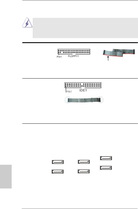
Onboard headers and connectors are NOT jumpers. Do NOT place jumper caps over these headers and connectors. Placing jumper caps over the headers and connectors will cause permanent damage of the motherboard!
Floppy Connector
(33-pin FLOPPY1)
(see p.2 No. 20)
the red-striped side to Pin1
Note: Make sure the red-striped side of the cable is plugged into Pin1 side of the connector.
Primary IDE connector
(39-pin IDE1, see p.2 No. 6)
connect the blue end |
connect the black end |
to the motherboard |
to the IDE devices |
80-conductor ATA 66/100/133 cable
Note: Please refer to the instruction of your IDE device vendor for the details.
Serial ATA2 Connectors |
These six Serial ATA2 (SATA2) |
||
(SATAII_1 (PORT 0): |
connectors support SATA data |
||
see |
p.2, No. 14) |
cables for internal storage |
|
(SATAII_2 (PORT 1): |
devices. The current SATA2 |
||
see |
p.2, No. 15) |
interface allows up to 3.0 Gb/s |
|
(SATAII_3 (PORT 2): |
data transfer rate. |
||
see |
p.2, No. 12) |
|
|
(SATAII_4 (PORT 3): |
SATAII_6 (PORT 5) |
||
see |
p.2, No. 11) |
||
SATAII_4 (PORT 3) |
|||
|
SATAII_2 (PORT 1) |
||
(SATAII_5 (PORT 4): |
|
||
see |
p.2, No. 10) |
SATAII_5 (PORT 4) |
|
SATAII_3 (PORT 2) |
|||
|
SATAII_1 (PORT 0) |
||
(SATAII_6 (PORT 5): |
|
||
see |
p.2, No. 9) |
|
|
14
ASRock 960GC-GS FX Motherboard
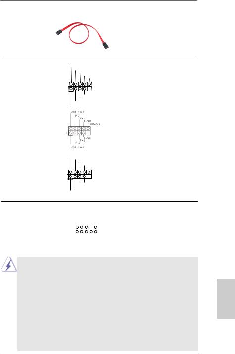
Serial ATA (SATA) Data Cable
(Optional)
USB 2.0 Headers |
USB_PWR |
(9-pin USB4_5) |
P-4 |
P+4 |
|
|
GND |
(see p.2 No. 18) |
DUMMY |
|
|
|
1 |
|
GND |
|
P+5 |
|
P-5 |
|
USB_PWR |
(9-pin USB6_7)
(see p.2 No. 17)
Either end of the SATA data cable can be connected to the SATA2 hard disk or the SATA2 connector on this motherboard.
Besides four default USB 2.0 ports on the I/O panel, there are three USB 2.0 headers on this motherboard. Each USB 2.0 header can support two USB 2.0 ports.
(9-pin USB8_9) |
USB_PWR |
|
(see p.2 No. 16) |
||
P-9 |
||
|
P+9 |
|
|
GND |
|
|
DUMMY |
|
|
1 |
|
|
GND |
|
|
P+8 |
|
|
P-8 |
|
|
USB_PWR |
Front Panel Audio Header |
|
|
GND |
|||||||||
(9-pin HD_AUDIO1) |
|
|
|
|
PRESENCE# |
|||||||
|
|
|
|
|
|
MIC_RET |
||||||
|
|
|
|
|
|
|
|
|
|
|
OUT_RET |
|
(see p.2 No. 25) |
1 |
|
|
|
|
|
|
|
|
|
|
|
|
|
|
|
|
|
|
|
|
|
|
|
|
|
|
|
|
|
|
|
|
|
|
|
|
|
|
|
|
|
|
|
|
|
|
|
|
OUT2_L |
|
|
|
|
|
|
|
|
|
J_SENSE |
||||
|
|
|
|
|
|
|
OUT2_R |
|||||
|
|
|
|
|
MIC2_R |
|||||||
|
|
|
MIC2_L |
|||||||||
This is an interface for the front panel audio cable that allows convenient connection and control of audio devices.
1.High Definition Audio supports Jack Sensing, but the panel wire on the chassis must support HDA to function correctly. Please follow the instruction in our manual and chassis manual to install your system.
2.If you use AC’97 audio panel, please install it to the front panel audio header as below:
A.Connect Mic_IN (MIC) to MIC2_L.
B.Connect Audio_R (RIN) to OUT2_R and Audio_L (LIN) to OUT2_L.
C.Connect Ground (GND) to Ground (GND).
D.MIC_RET and OUT_RET are for HD audio panel only. You don’t need to connect them for AC’97 audio panel.
E.To activate the front mic.
For Windows® XP / XP 64-bit OS:
Select “Mixer”. Select “Recorder”. Then click “FrontMic”.
15
English
ASRock 960GC-GS FX Motherboard

For Windows® 8 / 8 64-bit / 7 / 7 64-bit / VistaTM / VistaTM 64-bit OS: Go to the "FrontMic" Tab in the Realtek Control panel. Adjust “Recording Volume”.
SPDIF Out Connector
(2-pin SPDIF_OUT1)
(see p.2 No. 24)
1 |
GND
SPDIFOUT
Please connect the SPDIF_OUT connector of a HDMI VGA card to this header with a cable.
System Panel Header |
This header accommodates |
(9-pin PANEL1) |
several system front panel |
(see p.2 No. 19) |
functions. |
English
16
Connect the power switch, reset switch and system status indicator on the chassis to this header according to the pin assignments below. Note the positive and negative pins before connecting the cables.
PWRBTN (Power Switch):
Connect to the power switch on the chassis front panel. You may configure the way to turn off your system using the power switch.
RESET (Reset Switch):
Connect to the reset switch on the chassis front panel. Press the reset switch to restart the computer if the computer freezes and fails to perform a normal restart.
PLED (System Power LED):
Connect to the power status indicator on the chassis front panel. The LED is on when the system is operating. The LED keeps blinking when the sys-tem is in S1 sleep state. The LED is off when the system is in S3/S4 sleep state or powered off (S5).
HDLED (Hard Drive Activity LED):
Connect to the hard drive activity LED on the chassis front panel. The LED is on when the hard drive is reading or writing data.
The front panel design may differ by chassis. A front panel module mainly consists of power switch, reset switch, power LED, hard drive activity LED, speaker and etc. When connecting your chassis front panel module to this header, make sure the wire assignments and the pin assign-ments are matched correctly.
ASRock 960GC-GS FX Motherboard

Chassis Speaker Header |
Please connect the chassis |
(4-pin SPEAKER 1) |
speaker to this header. |
(see p.2, No. 13) |
|
|
|
Infrared Module Header |
This header supports an |
(5-pin IR1) |
optional wireless transmitting |
(see p.2, No. 21) |
and receiving infrared module. |
Print Port Header |
AFD# |
|
(25-pin LPT1) |
ERROR# |
GND |
SLIN# |
||
|
PINIT# |
|
(see p.2 No. 23) |
|
|
|
1 |
|
|
|
SPD7 |
|
SPD6 ACK# |
|
|
SPD5 |
BUSY |
|
SPD4 |
PE |
|
SPD3 |
SLCT |
|
SPD2 |
|
|
SPD1 |
|
|
SPD0 |
|
|
STB# |
|
This is an interface for print port cable that allows convenient connection of printer devices.
Chassis Intrusion Header
(2-pin CI1) |
1 |
|
|
|
|
|
|
|
|
|
GND |
||||
(see p.2 No. 22) |
Signal |
||||||
This motherboard supports CASE OPEN detection feature that detects if the chassis cover has been removed. This feature requires a chassis with chassis intrusion detection design.
Internal Audio Connectors |
|
This connector allows you |
(4-pin CD1) |
|
to receive stereo audio input |
(CD1: see p.2 No. 26) |
CD1 |
from sound sources such as |
|
|
a CD-ROM, DVD-ROM, TV |
|
|
tuner card, or MPEG card. |
Chassis and Power Fan Connectors
(3-pin CHA_FAN1) |
GND |
(see p.2 No. 8) |
+12V |
CHA_FAN_SPEED |
|
|
+12V |
(3-pin PWR_FAN1) |
GND PWR_FAN_SPEED |
(see p.2 No. 27) |
|
Please connect the fan cable to the fan connector and match the black wire to the ground pin.
17
English
ASRock 960GC-GS FX Motherboard
 Loading...