


4CoreDual-SATA2
User Manual
Version 2.0
PublishedNovember 2007
Copyright©2007 ASRock INC. All rights reserved.
1
Copyright Notice:
No part of this manual may be reproduced, transcribed, transmitted, or translated in any language, in any form or by any means, except duplication of documentation by the purchaser for backup purpose, without written consent of ASRock Inc.
Products and corporate names appearing in this manual may or may not be registered trademarks or copyrights of their respective companies, and are used only for identification or explanation and to the owners’ benefit, without intent to infringe.
Disclaimer:
Specifications and information contained in this manual are furnished for informational use only and subject to change without notice, and should not be constructed as a commitment by ASRock. ASRock assumes no responsibility for any errors or omissions that may appear in this manual.
With respect to the contents of this manual, ASRock does not provide warranty of any kind, either expressed or implied, including but not limited to the implied warranties or conditions of merchantability or fitness for a particular purpose.
In no event shall ASRock, its directors, officers, employees, or agents be liable for any indirect, special, incidental, or consequential damages (including damages for loss of profits, loss of business, loss of data, interruption of business and the like), even if ASRock has been advised of the possibility of such damages arising from any defect or error in the manual or product.
This device complies with Part 15 of the FCC Rules. Operation is subject to the following two conditions:
(1)this device may not cause harmful interference, and
(2)this device must accept any interference received, including interference that may cause undesired operation.
CALIFORNIA, USA ONLY
The Lithium battery adopted on this motherboard contains Perchlorate, a toxic substance controlled in Perchlorate Best Management Practices (BMP) regulations passed by the California Legislature. When you discard the Lithium battery in California, USA, please follow the related regulations in advance.
“Perchlorate Material-special handling may apply, see www.dtsc.ca.gov/hazardouswaste/perchlorate”
ASRock Website: http://www.asrock.com
2

|
Contents |
|
1. Introduction.................................................. |
5 |
|
1.1 |
Package Contents .......................................................... |
5 |
1.2 |
Specifications ................................................................ |
6 |
1.3 |
Minimum Hardware Requirement Table for Windows® |
|
|
VistaTM Premium 2007 and Basic OS............................ |
9 |
1.4 |
Supported PCI Express VGA Card List for PCI |
|
|
Express Graphics Slot ................................................... |
10 |
1.5 |
Motherboard Layout ...................................................... |
11 |
1.6 |
ASRock 6CH Premium I/O Panel .................................. |
12 |
2. Installation .................................................... |
13 |
|
2.1 |
Screw Holes ................................................................. |
13 |
2.2 |
Pre-installation Precautions ........................................... |
13 |
2.3 |
CPU Installation .............................................................. |
14 |
2.4 |
Installation of Heatsink and CPU fan ............................. |
16 |
2.5 |
Installation of Memory Modules (DIMM) ......................... |
17 |
2.6 |
Expansion Slots ............................................................. |
19 |
2.7 |
Surround Display Feature ............................................. |
20 |
2.8 |
Jumpers Setup .............................................................. |
20 |
2.9 |
Onboard Headers and Connectors .............................. |
21 |
2.10 HDMI_SPDIF Header Connection Guide ........................ |
26 |
|
2.11 SATAII Hard Disk Setup Guide ....................................... |
27 |
|
2.12 Serial ATA (SATA) / Serial ATAII (SATAII) Hard Disks |
|
|
|
Installation .................................................................... |
28 |
2.13 Hot Plug and Hot Swap Functions for SATA / SATAII |
|
|
|
HDDs ............................................................................ |
28 |
2.14 SATA / SATAII HDD Hot Plug Feature and Operation |
|
|
|
Guide .......................................................................... |
29 |
2.15 Driver Installation Guide .................................................. |
31 |
|
2.16 |
Installing Windows® 2000 / XP / XP 64-bit / VistaTM / |
|
|
VistaTM 64-bit With RAID Functions ............................... |
31 |
|
2.16.1 Installing Windows® 2000 / XP / XP 64-bit With |
|
|
RAID Functions .................................................... |
31 |
|
2.16.2 Installing Windows® VistaTM / VistaTM 64-bit With |
|
|
RAID Functions .................................................... |
32 |
2.17 Installing Windows® 2000 / XP / XP 64-bit / VistaTM / |
|
|
|
VistaTM 64-bit Without RAID Functions ......................... |
33 |
2.18 |
Untied Overclocking Technology ................................ |
33 |
3

3. BIOS SETUP UTILITY ........................................ |
34 |
||
3.1 |
Introduction .................................................................... |
34 |
|
|
3.1.1 BIOS Menu Bar .................................................... |
34 |
|
|
3.1.2 Navigation Keys .................................................... |
35 |
|
3.2 |
Main Screen ................................................................... |
35 |
|
3.3 |
Advanced Screen ......................................................... |
36 |
|
|
3.3.1 CPU Configuration ................................................ |
36 |
|
|
3.3.2 |
Chipset Configuration .......................................... |
38 |
|
3.3.3 ACPI Configuration ............................................... |
41 |
|
|
3.3.4 IDE Configuration ................................................. |
42 |
|
|
3.3.5 PCIPnP Configuration ........................................... |
44 |
|
|
3.3.6 |
Floppy Configuration ........................................... |
44 |
|
3.3.7 |
Super IO Configuration ........................................ |
45 |
|
3.3.8 |
USB Configuration ............................................... |
46 |
3.4 |
Hardware Health Event Monitoring Screen .................. |
47 |
|
3.5 |
Boot Screen ................................................................... |
48 |
|
|
3.5.1 Boot Settings Configuration .................................. |
49 |
|
3.6 |
Security Screen ............................................................ |
49 |
|
3.7 |
Exit Screen .................................................................... |
50 |
|
4. Software Support .......................................... |
51 |
||
4.1 |
Install Operating System ............................................... |
51 |
|
4.2 |
Support CD Information ................................................. |
51 |
|
|
4.2.1 Running Support CD ............................................ |
51 |
|
|
4.2.2 Drivers Menu ........................................................ |
51 |
|
|
4.2.3 |
Utilities Menu ........................................................ |
51 |
|
4.2.4 |
Contact Information .............................................. |
51 |
4
1. Introduction
Thank you for purchasing ASRock 4CoreDual-SATA2 motherboard, a reliable motherboard produced under ASRock’s consistently stringent quality control. It delivers excellent performance with robust design conforming to ASRock’s commitment to quality and endurance.
In this manual, chapter 1 and 2 contain introduction of the motherboard and step-by- step guide to the hardware installation. Chapter 3 and 4 contain the configuration guide to BIOS setup and information of the Support CD.
Because the motherboard specifications and the BIOS software might be updated, the content of this manual will be subject to change without notice. In case any modifications of this manual occur, the updated version will be available on ASRock website without further notice. You may find the latest VGA cards and CPU support lists on ASRock website as well. ASRock website http://www.asrock.com
If you require technical support related to this motherboard, please visit our website for specific information about the model you are using. www.asrock.com/support/index.asp
1.1 Package Contents
ASRock 4CoreDual-SATA2 Motherboard
(ATX Form Factor: 12.0-in x 9.6-in, 30.5 cm x 24.4 cm) ASRock 4CoreDual-SATA2 Quick Installation Guide ASRock 4CoreDual-SATA2 Support CD
One 80-conductor Ultra ATA 66/100/133 IDE Ribbon Cable One Ribbon Cable for a 3.5-in Floppy Drive
One Serial ATA (SATA) Cable (Optional)
One Serial ATA (SATA) HDD Power Cable (Optional) One HDMI_SPDIF Cable (Optional)
One ASRock 6CH Premium I/O Panel Shield
5

1.2Specifications
Platform |
- ATX Form Factor: 12.0-in x 9.6-in, 30.5 cm x 24.4 cm |
CPU |
- LGA 775 for Intel® CoreTM 2 Extreme / CoreTM 2 Quad / |
|
CoreTM 2 Duo / Pentium® XE / Pentium® D / Pentium® Dual Core |
|
/ Pentium® 4 / Celeron® / Celeron® D, supporting Quad Core |
|
Kentsfield processors (see CAUTION 1) |
|
- FSB 1066/800/533 MHz |
|
- Supports Hyper-Threading Technology (see CAUTION 2) |
|
- Supports Untied Overclocking Technology (see CAUTION 3) |
|
- Supports EM64T CPU |
Chipset |
- Northbridge: VIA® PT880 Pro/PT880 Ultra |
|
- Southbridge: VIA® VT8237S |
Memory |
- Dual Channel DDR/DDR2 Memory Technology |
|
(see CAUTION 4) |
|
- 2 x DDR2 DIMM slots |
|
- Support DDR2 667/533 |
|
- Max. capacity: 2GB |
|
- 2 x DDR DIMM slots |
|
- Support DDR400/333/266 |
|
- Max. capacity: 2GB |
Hybrid Booster |
- CPU Frequency Stepless Control (see CAUTION 5) |
|
- ASRock U-COP (see CAUTION 6) |
|
- Boot Failure Guard (B.F.G.) |
Expansion Slot |
- 1 x PCI Express Graphics slot (see CAUTION 7) |
|
- 1 x AGP 8X slot (see CAUTION 8) |
|
- 4 x PCI slots |
Audio |
- 5.1 CH Windows® VistaTM Premium Level HD Audio |
|
(ALC662 Audio Codec) |
LAN |
- VIA® PHY VT6103 |
|
- Speed: 10/100 Ethernet |
|
- Supports Wake-On-LAN |
Rear Panel I/O |
ASRock 6CH Premium I/O |
|
- 1 x PS/2 Mouse Port |
|
- 1 x PS/2 Keyboard Port |
|
- 1 x Serial Port: COM1 |
|
- 1 x Parallel Port (ECP/EPP Support) |
|
- 4 x Ready-to-Use USB 2.0 Ports |
|
- 1 x RJ-45 Port |
|
- HD Audio Jack: Rear Speaker / Central/Bass / Line in / Front |
|
Speaker / Microphone (see CAUTION 9) |
6
Connector |
- 2 x Serial ATAII 3.0Gb/s connectors, support RAID (RAID 0, |
|
|
RAID 1, and JBOD) and “Hot Plug” functions |
|
|
(see CAUTION 10) |
|
|
- 2 x ATA133 IDE connectors (support 4 x IDE devices) |
|
|
- 1 x Floppy connector |
|
|
- 1 x IR header |
|
|
- 1 x Game header |
|
|
- 1 x HDMI_SPDIF header |
|
|
- CPU/Chassis FAN connector |
|
|
- 20 pin ATX power connector |
|
|
- 4 pin 12V power connector |
|
|
- CD in header |
|
|
- Front panel audio connector |
|
|
- 2 x USB 2.0 headers (support 4 USB 2.0 ports) |
|
|
(see CAUTION 11) |
|
BIOS Feature |
- 4Mb AMI BIOS |
|
|
- AMI Legal BIOS |
|
|
- Supports “Plug and Play” |
|
|
- ACPI 1.1 Compliance Wake Up Events |
|
|
- Supports jumperfree |
|
|
- SMBIOS 2.3.1 Support |
|
Support CD |
- Drivers, Utilities, AntiVirus Software (Trial Version) |
|
Hardware |
- CPU Temperature Sensing |
|
Monitor |
- Chassis Temperature Sensing |
|
|
- CPU Fan Tachometer |
|
|
- Chassis Fan Tachometer |
|
|
- CPU Quiet Fan |
|
|
- Voltage Monitoring: +12V, +5V, +3.3V, Vcore |
|
OS |
- Microsoft® Windows® 2000 / XP / XP 64-bit / VistaTM / |
|
|
VistaTM 64-bit compliant |
|
Certifications |
- FCC, CE, WHQL |
|
WARNING
Please realize that there is a certain risk involved with overclocking, including adjusting the setting in the BIOS, applying Untied Overclocking Technology, or using the thirdparty overclocking tools. Overclocking may affect your system stability, or even cause damage to the components and devices of your system. It should be done at your own risk and expense. We are not responsible for possible damage caused by overclocking.
7

CAUTION!
1.When you adopt Quad Core CPU on this motherboard, FSB frequency may be reduced 5%.
2.About the setting of “Hyper Threading Technology”, please check page 37.
3.This motherboard supports Untied Overclocking Technology. Please read “Untied Overclocking Technology” on page 33 for details.
4.This motherboard supports Dual Channel Memory Technology. Before you implement Dual Channel Memory Technology, make sure to read the installation guide of memory modules on page 17 for proper installation.
5.Although this motherboard offers stepless control, it is not recommended to perform over-clocking. Frequencies other than the recommended CPU bus frequencies may cause the instability of the system or damage the CPU.
6.While CPU overheat is detected, the system will automatically shutdown. Before you resume the system, please check if the CPU fan on the motherboard functions properly and unplug the power cord, then plug it back again. To improve heat dissipation, remember to spray thermal grease between the CPU and the heatsink when you install the PC system.
7.For the information of the compatible PCI Express VGA cards, please refer to the “Supported PCI Express VGA Card List for PCI Express Graphics Slot” on page 10. For the proper installation of PCI Express VGA card, please refer to the installation guide on page 19.
8.Do NOT use a 3.3V AGP card on the AGP slot of this motherboard! It may cause permanent damage!
9.For microphone input, this motherboard supports both stereo and mono modes. For audio output, this motherboard supports 2-channel, 4-channel and 6-channel modes. Please check the table on page 12 for proper connection.
10.Before installing SATAII hard disk to SATAII connector, please read the “SATAII Hard Disk Setup Guide” on page 27 to adjust your SATAII hard disk drive to SATAII mode. You can also connect SATA hard disk to SATAII connector directly.
11.Power Management for USB 2.0 works fine under Microsoft® Windows® VistaTM 64-bit / VistaTM / XP 64-bit / XP SP1 or SP2 / 2000 SP4.
8

1.3Minimum Hardware Requirement Table for Windows®
VistaTM Premium 2007 and Basic OS
This motherboard can support all features in Windows® VistaTM Premium 2007. Please follow below table for minimum hardware requirement.
CPU |
Celeron D 326 |
Memory |
1GB system memory (Premium) |
|
512MB Single Channel (Basic) |
VGA |
DX9.0 with WDDM Driver |
|
with 128bit VGA memory (Premium) |
|
with 64bit VGA memory (Basic) |
9

1.4Supported PCI Express VGA Card List for PCI
Express Graphics Slot
(for Windows® 2000/XP/XP 64-bit/VistaTM/VistaTM 64-bit)
Graphics Chip |
Model Name |
Chip Name |
Vendor |
|
|
NVIDIA |
ASUS Extreme N6800GT |
GeForce 6800GT |
|
ASUS EN7600GT/2DHT |
GeForce 7600GT |
|
ASUS Extreme N7800GTX/2DHTV |
GeForce 7800 GTX |
|
ALBATRON PC6600GT |
GeForce 6600GT |
|
Gigabyte GV-NX71G512P8 |
GeForce 7100GS |
|
GIGABYTE GF-8500GT |
GeForce 8600 GTS |
|
LEADTEK PX6500 TDH |
GeForce 6500 |
|
LEADTEK PX7300GS TDH |
GeForce 7300 GS |
|
LEADTEK PX7300LE-TDH |
GeForce 7300 LE |
|
LEADTEK PX7900GS TDH |
GeForce 7900GS |
|
MSI PCX 5750-TD128E |
GeForce PCX5750 |
|
MSI NX8600GTS |
GeForce 8600 GTS |
|
MSI NX8800GTS/320M |
GeForce 8800 GTS |
ATI |
ASUS EAX1900XT/2DHTV |
RadeonX1900XT |
|
GECUBE Radeon X850XT 256M |
RADEON X850XT |
|
MSI RX1300PRO-TD256E |
RADEON X1300Pro |
|
MSI RX1600PRO-TD256E |
RADEON X1600Pro |
|
MSI RX1600XT-T2D256EZ |
RADEON X1600XT |
|
|
|
For the latest updates of the supported PCI Express VGA card list for PCI Express Graphics slot, please visit ASRock website for details.
ASRock website: http://www.asrock.com/support/index.htm
1 0

1.5 Motherboard Layout
29
28
27
26
25
24
|
|
1 |
|
2 |
|
3 |
4 |
|
5 |
|
|
|
|
6 |
7 |
|
|
|
|
|
|
24.4cm (9.6 in) |
|
|
|
|
|
|
|
|
|
|
|
|
1 |
PS2_USB_PWR1 |
|
|
|
|
|
|
|
|
|
|
|
|
||
PS2 |
|
|
|
|
|
|
|
|
|
|
|
|
|
|
|
|
Mouse |
|
|
|
|
|
|
|
|
|
|
|
|
|
|
|
|
Keyboard PS2 |
PARALLEL |
ATX12V1 |
|
|
|
|
|
|
DDR400/DDRII667 |
|
|
|
|
|
||
LINEIN Top: |
|
|
ATXPWR1 |
|
|
Conroe |
Kentsfield FSB1066 |
CPUCoreQuad |
bit,(64/721DDRII240-pinmodule) |
odule)m pin-184it,b64/72(DDR1 |
|
bit,(64/722DDRII240-pinmodule) |
odule)m pin-184it,b64/72DDR2( |
|||
MICIN Bottom: |
FRONT Center: |
|
|
|
|
|
||||||||||
COM1 |
PORT |
|
|
|
|
|
|
CPU_FAN1 |
Channel |
|
|
|
|
|
|
|
T: USB2 |
|
|
|
|
|
|
|
|
Dual |
|
|
|
|
|
|
|
USB 2.0 |
|
|
|
|
|
|
|
|
|
|
|
|
|
|
|
|
B: USB3 |
|
|
|
|
|
|
|
|
|
|
|
|
|
|
|
|
USB 2.0 |
Top: |
|
|
|
|
|
|
|
|
|
|
|
|
|
|
|
T: USB0 |
|
|
|
|
|
|
|
|
|
|
|
|
|
|
||
RJ-45 |
|
|
|
|
|
|
|
|
|
|
|
|
|
|
||
B: USB1 |
|
|
|
|
|
|
|
|
|
|
|
|
|
|
|
|
CTR Bottom: BASS |
REAR Top: SPK |
|
|
|
|
VIA |
|
|
|
|
|
|
|
|
|
|
|
|
|
|
|
|
PT880 Pro / |
|
|
|
|
|
|
|
|
|
|
|
|
|
|
|
|
PT880 Ultra |
|
|
|
|
|
|
|
|
|
|
|
|
|
|
|
|
Chipset |
|
|
|
|
|
|
|
|
|
|
|
|
|
CD1 |
|
|
|
|
|
|
|
|
|
|
|
|
|
|
|
1 |
|
|
|
|
|
PCI |
|
|
|
|
|
|
|
|
|
|
IR1 |
|
|
AGP 8X |
|
|
|
|
|
|
|
|
|
|
|
|
|
Super |
|
|
|
|
EXPRESS |
|
|
|
|
|
|
|||
|
|
I/O |
|
|
1.5V_AGP1 |
|
|
|
|
|
|
|
|
|
|
|
|
|
|
|
|
PCIE_GRAPHICS1 |
|
|
|
|
|
|
|
|
|
IDE1 IDE2 |
|
|
|
|
|
|
|
|
|
|
|
|
|
RAID |
|
|||
|
|
|
|
|
|
|
|
|
|
|
|
|
|
|
||
|
|
|
|
|
|
PCI 1 |
|
|
|
|
|
|
|
|
ATA133 |
|
|
LAN |
|
4CoreDual-SATA2 |
|
|
|
|
|
|
|
|
|
||||
|
PHY |
|
|
|
|
|
|
|
|
|
|
|
||||
|
|
|
|
|
|
PCI 2 |
CMOS |
|
|
|
VIA |
|
|
|
||
|
|
|
|
|
|
|
|
|
|
|
|
|
||||
|
1 |
|
|
|
|
USB2.0 |
Battery |
|
|
VT8237S |
|
|
||||
|
HD_AUDIO1 |
|
|
|
|
|
|
|
||||||||
|
|
|
|
|
|
PCI 3 |
|
CLRCMOS1 |
|
|
|
|
|
|
|
|
|
|
|
|
|
|
|
RoHS |
|
|
|
|
|
|
|
||
|
|
Audio |
|
|
|
|
|
|
|
|
|
|
|
|
SATA1 SATA2 |
|
|
|
CODEC |
|
|
|
PCI 4 |
|
|
|
|
|
4Mb |
|
|||
|
|
|
|
|
|
|
|
|
|
|
|
|
|
|||
|
|
|
|
|
|
|
|
|
|
|
|
BIOS |
|
|
PLED PWRBTN |
|
|
|
|
|
|
|
|
|
USB67 |
USB45 |
|
|
|
CHA_FAN1 |
|
PANEL 1 |
|
|
|
HDMI_SPDIF1 |
GAME1 |
|
FLOPPY1 |
|
|
|
|
|
SPEAKER1 |
|
||||
|
|
1 |
|
1 |
|
|
1 |
|
1 |
|
|
|
|
1 |
|
1 |
|
|
|
|
|
|
|
|
|
|
|
|
|
|
|
|
HDLED RESET |
|
|
23 |
|
22 |
|
21 |
|
2019 18 |
|
17161514 |
13 |
|||||
30.5cm (12.0 in)
8
9
10
11
12
1 |
PS2_USB_PWR1 Jumper |
15 |
Chassis Fan Connector (CHA_FAN1) |
2 |
ATX 12V Connector (ATX12V1) |
16 |
South Bridge Controller |
3 |
775-Pin CPU Socket |
17 |
Flash Memory |
4 |
North Bridge Controller |
18 |
USB 2.0 Header (USB45, Blue) |
5 |
CPU Fan Connector (CPU_FAN1) |
19 |
Clear CMOS Jumper (CLRCMOS1) |
6 |
2 x 240-pin DDR2 DIMM Slots |
20 |
USB 2.0 Header (USB67, Blue) |
|
(Dual Channel A: DDRII_1, DDRII_2; Yellow) |
21 |
Floppy Connector (FLOPPY1) |
7 |
2 x 184-pin DDR DIMM Slots |
22 |
Game Connector (GAME1) |
|
(Dual Channel B: DDR1, DDR2; Blue) |
23 |
HDMI_SPDIF Header (HDMI_SPDIF1) |
8 |
AGP Slot (1.5V_AGP1) |
24 |
Front Panel Audio Header (HD_AUDIO1) |
9 |
Primary IDE Connector (IDE1, Blue) |
25 |
4 x PCI Slots (PCI1- 4) |
10 |
Secondary IDE Connector (IDE2, Black) |
26 |
PCI Express Graphics Slot |
11 |
Secondary Serial ATAII Connector (SATA2) |
27 |
Infrared Module Header (IR1) |
12 |
Primary Serial ATAII Connector (SATA1) |
28 |
Internal Audio Connector: CD1 (Black) |
13 |
System Panel Header (PANEL1) |
29 |
ATX Power Connector (ATXPWR1) |
14 |
Chassis Speaker Header (SPEAKER 1) |
|
|
1 1
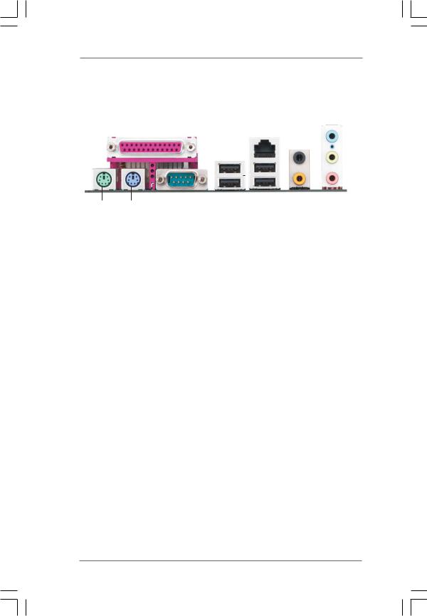
1.5 ASRock 6CH Premium I/O Panel
1 |
|
2 |
|
|
|
|
|
|
|
|
|
|
|
|
||||||
|
|
|
|
|
|
|
|
|
|
|
|
|
|
|
|
|
|
|
5 |
|
|
|
|
|
|
|
|
|
|
|
|
|
|
|
|
|
|
|
|
||
|
|
|
|
|
|
|
|
|
|
|
|
|
|
|
|
|
|
|
||
|
|
|
|
|
|
|
|
|
|
|
|
|
|
|
|
|
|
|
||
|
|
|
|
|
|
|
|
|
|
|
|
|
|
|
3 |
|
|
|
|
6 |
|
|
|
|
|
|
|
|
|
|
|
|
|
|
|
|
|
|
|
||
|
|
|
|
|
|
|
|
|
|
|
|
|
|
|
|
|
||||
|
|
|
|
|
|
|
|
|
|
|
|
|
|
|
|
|||||
|
|
|
|
|
|
|
|
|
|
|
|
|
|
4 |
|
|
7 |
|||
|
|
|
|
|
|
|
|
|
|
|
|
|
|
|||||||
|
|
|
|
|
|
|
|
|
|
|
|
|||||||||
|
|
|
|
|
|
|
|
|
|
|
|
|
||||||||
|
|
|
|
|
|
|
|
|
|
|
|
|
|
|||||||
|
|
|
|
|
|
|
|
|
|
|
|
|
|
|
|
|
|
|
|
|
|
|
|
|
|
|
|
|
|
|
|
|
|
|
|
|
|
|
|
|
|
12 |
|
11 |
10 |
9 |
|
|
8 |
|
1 |
Parallel Port |
|
7 |
Microphone (Pink) |
||||
2 |
RJ-45 Port |
|
8 |
USB 2.0 |
Ports |
(USB01) |
||
3 |
Rear |
Speaker |
(Black) |
9 |
USB 2.0 |
Ports |
(USB23) |
|
4 |
Central / Bass |
(Orange) |
10 |
Serial |
Port: COM1 |
|||
5 |
Line |
In (Light Blue) |
11 |
PS/2 |
Keyboard |
Port (Purple) |
||
* 6 |
Front |
Speaker |
(Lime) |
12 |
PS/2 |
Mouse Port (Green) |
||
*If you use 2-channel speaker, please connect the speaker’s plug into “Front Speaker Jack”. See the table below for connection details in accordance with the type of speaker you use.
TABLE for Audio Output Connection
Audio Output Channels |
Front Speaker |
Rear Speaker |
Central / Bass |
|
(No. 6) |
(No. 3) |
(No. 4) |
2 |
V |
-- |
-- |
|
|
|
|
4 |
V |
V |
-- |
6 |
V |
V |
V |
*To enable Multi-Streaming function, you need to connect a front panel audio cable to the front panel audio header. Please refer to below steps for the software setting of Multi-Streaming.
For Windows® XP:
After restarting your computer, you will find “Mixer” tool on your system. Please select “Mixer ToolBox”  , click “Enable playback multi-streaming”, and click “ok”. Choose “2CH” or
“4CH” and then you are allowed to select “Realtek HDA Primary output” to use Rear Speaker and Front Speaker, or select “Realtek HDA Audio 2nd output” to use front panel audio. Then reboot your system.
For Windows® VistaTM:
After restarting your computer, please double-click “Realtek HD Audio Manager” on the system tray. Set “Speaker Configuration” to “5.1 Speaker”. Click “Device advanced settings”, choose “Make front and rear output devices playbacks two different audio streams simultaneously”, and click “ok”. Then reboot your system.
1 2

Chapter 2 Installation
4CoreDual-SATA2 is an ATX form factor (12.0" x 9.6", 30.5 x 24.4 cm) motherboard. Before you install the motherboard, study the configuration of your chassis to ensure that the motherboard fits into it.
Make sure to unplug the power cord before installing or removing the motherboard. Failure to do so may cause physical injuries to you and damages to motherboard components.
2.1 Screw Holes
Place screws into the holes indicated by circles to secure the motherboard to the chassis.
Do not over-tighten the screws! Doing so may damage the motherboard.
2.2 Pre-installation Precautions
Take note of the following precautions before you install motherboard components or change any motherboard settings.
1.Unplug the power cord from the wall socket before touching any component.
2.To avoid damaging the motherboard components due to static electricity, NEVER place your motherboard directly on the carpet or the like. Also remember to use a grounded wrist strap or touch a safety grounded object before you handle components.
3.Hold components by the edges and do not touch the ICs.
4.Whenever you uninstall any component, place it on a grounded antistatic pad or in the bag that comes with the component.
Before you install or remove any component, ensure that the power is switched off or the power cord is detached from the power supply.
Failure to do so may cause severe damage to the motherboard, peripherals, and/or components.
1 3

2.3 775-LAND CPU Installation
For the installation of Intel 775-LAND CPU, please follow the steps below.
775-Pin Socket Overview
Before you insert the 775-LAND CPU into the socket, please check if the CPU surface is unclean or if there is any bent pin on the socket. Do not force to insert the CPU into the socket if above situation is found. Otherwise, the CPU will be seriously damaged.
Step 1. Open the socket:
Step 1-1. Disengaging the lever by depressing down and out on the hook to clear retention tab.
Step 1-2. Rotate the load lever to fully open position at approximately 135 degrees.
Step 1-3. Rotate the load plate to fully open position at approximately 100 degrees.
Step 2. Insert the 775-LAND CPU:
Step 2-1. Hold the CPU by the edges where are marked with black lines.
Step 2-2. Orient the CPU with IHS (Integrated
Heat Sink) up. Locate Pin1 and the two orientation key notches.
lineblack |
lineblack |
Pin1 |
|
|
|
|
|
Pin1 |
|
|
|
|
alignment key |
||
|
|
|
|
|
|
|
|
|
|||||
|
|
|
|
|
|
|
|
|
|
|
|||
|
|
|
|
|
|
|
alignment key |
|
|
|
|
|
|
orientation |
orientation |
|
|
|
|
|
|||||||
|
|
|
|
|
|||||||||
|
|
|
|
|
|
|
|||||||
key notch |
key notch |
|
|
|
|
|
|
|
|||||
|
|
|
|
|
|
|
|
|
775-Pin Socket |
||||
|
|
|
|
775-LAND CPU |
|
|
|
|
|
|
|
||
1 4
For proper inserting, please ensure to match the two orientation key notches of the CPU with the two alignment keys of the socket.
Step 2-3. Carefully place the CPU into the socket by using a purely vertical motion.
Step 2-4. Verify that the CPU is within the socket and properly mated to the orient keys.
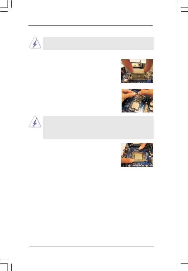
Step 3. Remove PnP Cap (Pick and Place Cap):
Use your left hand index finger and thumb to support the load plate edge, engage PnP cap with right hand thumb and peel the cap from the socket while pressing on center of PnP cap to assist in removal.
1.It is recommended to use the cap tab to handle and avoid kicking off the PnP cap.
2.This cap must be placed if returning the motherboard for after service.
Step 4. Close the socket:
Step 4-1. Rotate the load plate onto the IHS. Step 4-2. While pressing down lightly on load
plate, engage the load lever.
Step 4-3. Secure load lever with load plate tab under retention tab of load lever.
1 5
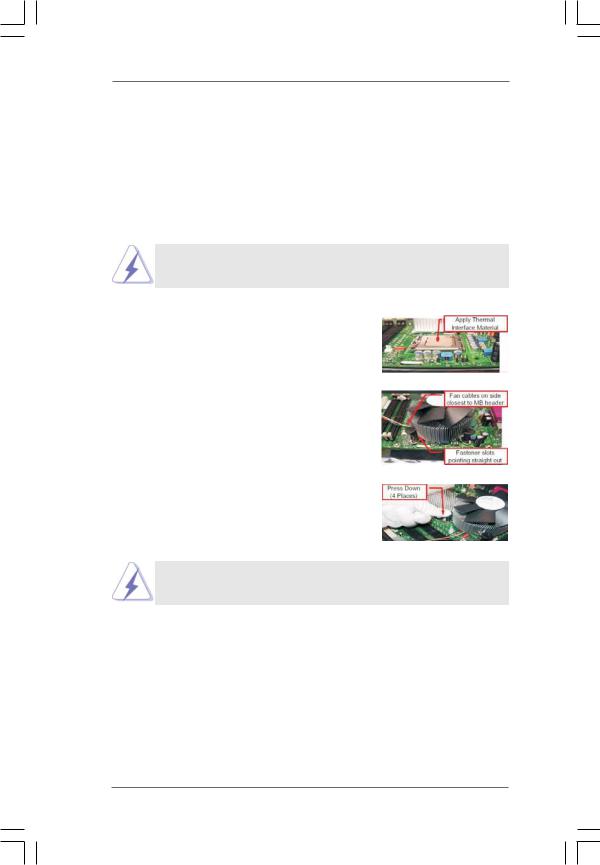
2.4Installation of CPU Fan and Heatsink
This motherboard is equipped with 775-Pin socket that supports Intel 775-LAND CPU. Please adopt the type of heatsink and cooling fan compliant with Intel 775-LAND CPU to dissipate heat. Before you installed the heatsink, you need to spray thermal interface material between the CPU and the heatsink to improve heat dissipation. Ensure that the CPU and the heatsink are securely fastened and in good contact with each other. Then connect the CPU fan to the CPU_FAN connector (CPU_FAN1, see page 11, No. 5).
For proper installation, please kindly refer to the instruction manuals of your CPU fan and heatsink.
Below is an example to illustrate the installation of the heatsink for 775-LAND CPU. Step 1. Apply thermal interface material onto center
of IHS on the socket surface.
Step 2. Place the heatsink onto the socket. Ensure fan cables are oriented on side closest to the CPU fan connector on the motherboard (CPU_FAN1, see page 11, No. 5).
Step 3. Align fasteners with the motherboard throughholes.
Step 4. Rotate the fastener clockwise, then press down on fastener caps with thumb to install and lock. Repeat with remaining fasteners.
If you press down the fasteners without rotating them clockwise, the heatsink cannot be secured on the motherboard.
Step 5. Connect fan header with the CPU fan connector on the motherboard.
Step 6. Secure excess cable with tie-wrap to ensure cable does not interfere with fan operation or contact other components.
1 6
 Loading...