


Copyright Notice:
No part of this installation guide may be reproduced, transcribed, transmitted, or translated in any language, in any form or by any means, except duplication of documentation by the purchaser for backup purpose, without written consent of ASRock Inc.
Products and corporate names appearing in this guide may or may not be registered trademarks or copyrights of their respective companies, and are used only for identification or explanation and to the owners’ benefit, without intent to infringe.
Disclaimer:
Specifications and information contained in this guide are furnished for informational use only and subject to change without notice, and should not be constructed as a commitment by ASRock. ASRock assumes no responsibility for any errors or omissions that may appear in this guide.
With respect to the contents of this guide, ASRock does not provide warranty of any kind, either expressed or implied, including but not limited to the implied warranties or conditions of merchantability or fitness for a particular purpose. In no event shall ASRock, its directors, officers, employees, or agents be liable for any indirect, special, incidental, or consequential damages (including damages for loss of profits, loss of business, loss of data, interruption of business and the like), even if ASRock has been advised of the possibility of such damages arising from any defect or error in the guide or product.
This device complies with Part 15 of the FCC Rules. Operation is subject to the following two conditions:
(1)this device may not cause harmful interference, and
(2)this device must accept any interference received, including interference that may cause undesired operation.
CALIFORNIA, USA ONLY
The Lithium battery adopted on this motherboard contains Perchlorate, a toxic substance controlled in Perchlorate Best Management Practices (BMP) regulations passed by the California Legislature. When you discard the Lithium battery in California, USA, please follow the related regulations in advance.
“Perchlorate Material-special handling may apply, see www.dtsc.ca.gov/hazardouswaste/perchlorate”
ASRock Website: http://www.asrock.com
Published November 2009
Copyright©2009 ASRock INC. All rights reserved.
1
English
ASRock A330ION Motherboard

Motherboard Layout
English
2
1 |
PS2_USB_PWR1 Jumper |
14 |
Third SATAII Connector (SATAII_3; Red) |
2 |
Chassis Fan Connector (CHA_FAN1) |
15 |
Primary SATAII Connector (SATAII_1; Red) |
3 |
CPU Heatsink |
16 |
Secondary SATAII Connector (SATAII_2; Red) |
4 |
CPU Fan Connector (CPU_FAN1) |
17 |
PCI Express 2.0 x16 Slot (PCIE1, Blue) |
5 |
Chipset Heatsink |
18 |
COM Port Header (COM1) |
6 |
Clear CMOS Jumper (CLRCMOS1) |
19 |
Front Panel Audio Header |
7 |
2 x 240-pin DDR3 DIMM Slots |
|
(HD_AUDIO1, Lime) |
|
(Dual Channel: DDR3_1, DDR3_2; Blue) |
20 |
HDMI_SPDIF Header |
8 |
ATX Power Connector (ATXPWR1) |
|
(HDMI_SPDIF1, Yellow) |
9 |
Chassis Fan Connector (CHA_FAN2) |
21 |
Chipset Fan |
10 |
Fourth SATAII Connector (SATAII_4; Red) |
22 |
USB 2.0 Header (USB8_9, Blue) |
11 |
System Panel Header (PANEL1, Orange) |
23 |
BIOS SPI Chip |
12 |
Infrared Module Header (IR1) |
24 |
USB 2.0 Header (USB6_7, Blue) |
13 |
Chassis Speaker Header (SPEAKER 1, Purple) |
|
|
ASRock A330ION Motherboard
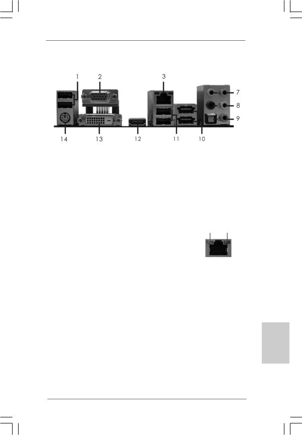
I/O Panel
1 |
USB 2.0 Ports |
** 8 |
Front Speaker (Lime) |
2 |
VGA/D-Sub Port |
9 |
Microphone (Pink) |
* 3 |
LAN RJ-45 Port |
*** 10 |
Powered eSATAII/USB Connectors |
4 |
Central / Bass (Orange) |
11 |
USB 2.0 Ports |
5 |
Rear Speaker (Black) |
12 |
HDMI Port |
6 |
Optical SPDIF Out Port |
13 |
VGA/DVI-D Port |
7 |
Line In (Light Blue) |
14 |
PS/2 Keyboard Port (Purple) |
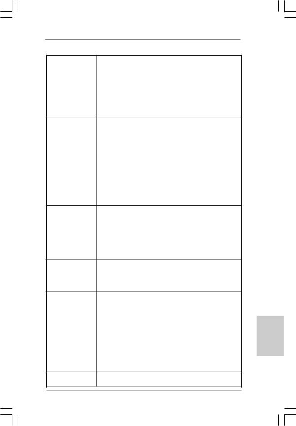
* There are two LED next to the LAN port. Please refer to the table below for the LAN port LED
indications. |
|
|
|
|
|
ACT/LINK |
SPEED |
|
|
|
LAN Port LED Indications |
||||||
|
|
LED |
LED |
|||||
Activity/Link LED |
|
SPEED LED |
||||||
|
|
|
||||||
Status |
|
Description |
|
Status |
|
Description |
|
|
Off |
|
No Link |
|
Off |
|
10Mbps connection |
|
|
Blinking |
|
Data Activity |
|
Orange |
|
100Mbps connection |
LAN Port |
|
On |
|
Link |
|
Green |
|
1Gbps connection |
||
|
|
|
|
|
||||
**If you use 2-channel speaker, please connect the speaker’s plug into “Front Speaker Jack”. See the table below for connection details in accordance with the type of speaker you use.
TABLE for Audio Output Connection
Audio Output Channels |
Front Speaker |
Rear Speaker |
Central / Bass |
Line In |
|
(No. 8) |
(No. 5) |
(No. 4) |
(No. 7) |
2 |
V |
-- |
-- |
-- |
4 |
V |
V |
-- |
-- |
6 |
V |
V |
V |
-- |
8 |
V |
V |
V |
V |
*** Powered eSATAII function is not supported in IDE mode.
English
3
ASRock A330ION Motherboard
To enable Multi-Streaming function, you need to connect a front panel audio cable to the front panel audio header. After restarting your computer, you will find “VIA HD Audio Deck” tool on your system. Please follow below instructions according to the OS you install.
For Windows® XP / XP 64-bit OS: |
|
Please click “VIA HD Audio Deck” icon |
, and click “Speaker”. Then you are allowed to |
select “2 Channel”, “4 Channel”, “6 Channel” or “8 Channel”. Click “Power” to save your change.
For Windows® 7 / 7 64-bit / VistaTM / VistaTM 64-bit OS:
Please click “VIA HD Audio Deck” icon |
, and click “Advanced Options” on the left side |
on the bottom. In “Advanced Options” screen, select “Independent Headphone”, and click “OK” to save your change.
English
4
ASRock A330ION Motherboard
1. Introduction
Thank you for purchasing ASRock A330ION motherboard, a reliable motherboard produced under ASRock’s consistently stringent quality control. It delivers excellent performance with robust design conforming to ASRock’s commitment to quality and endurance.
This Quick Installation Guide contains introduction of the motherboard and step-by- step installation guide. More detailed information of the motherboard can be found in the user manual presented in the Support CD.
Because the motherboard specifications and the BIOS software might be updated, the content of this manual will be subject to change without notice. In case any modifications of this manual occur, the updated version will be available on ASRock website without further notice. You may find the latest VGA cards and CPU support lists on ASRock website as well. ASRock website http://www.asrock.com
If you require technical support related to this motherboard, please visit our website for specific information about the model you are using. www.asrock.com/support/index.asp
1.1 Package Contents
ASRock A330ION Motherboard
(Mini-ITX Form Factor: 6.7-in x 6.7-in, 17.0 cm x 17.0 cm) One Bundled Intel® Dual-Core AtomTM Processor 330 ASRock A330ION Quick Installation Guide
ASRock A330ION Support CD
Two Serial ATA (SATA) Data Cables (Optional)
One Serial ATA (SATA) HDD Power Cable (Optional) One I/O Panel Shield
English
5
ASRock A330ION Motherboard

1.2Specifications
|
|
|
Platform |
- Mini-ITX Form Factor: 6.7-in x 6.7-in, 17.0 cm x 17.0 cm |
|
|
|
|
|
- All Solid Capacitor design (100% Japan-made high-quality |
|
|
|
|
|
Conductive Polymer Capacitors) |
|
|
|
|
CPU |
- Intel® Dual-Core AtomTM Processor 330 (1.6 GHz) |
|
|
|
|
|
- Supports Hyper-Threading Technology (see CAUTION 1) |
|
|
|
|
|
- Supports Untied Overclocking Technology (see CAUTION 2) |
|
|
|
|
|
- Supports EM64T |
|
|
|
|
|
|
|
|
|
|
Chipset |
-NVIDIA® MCP7A-ION |
|
|
|
|
Memory |
- Dual Channel DDR3 memory technology (see CAUTION 3) |
|
|
|
|
|
- 2 x DDR3 DIMM slots |
|
|
|
|
|
- Supports DDR3 1066/800 non-ECC, un-buffered memory |
|
|
|
|
|
- Max. capacity of system memory: 4GB (see CAUTION 4) |
|
|
|
|
Expansion Slot |
- 1 x PCI Express 2.0 x16 slot |
|
|
|
|
Graphics |
- Integrated NVIDIA® GeForce 9 Series |
|
|
|
|
|
- DX10 VGA, Pixel Shader 4.0 |
|
|
|
|
|
- Max. shared memory 512MB (see CAUTION 5) |
|
|
|
|
|
- Three VGA Output options: D-Sub, DVI-D and HDMI |
|
|
|
|
|
- Supports HDMI Technology with max. resolution up to |
|
|
|
|
|
1920x1200 (1080P) |
|
|
|
|
|
- Supports Dual-link DVI with max. resolution up to 2560x1600 |
|
|
|
|
|
@ 75Hz |
|
|
|
|
|
- Supports D-Sub with max. resolution up to 1920x1440 |
|
|
|
|
|
@ 75Hz |
|
|
|
|
|
- Supports HDCP function |
|
|
|
|
|
- Supports Full HD 1080p Blu-ray (BD) / HD-DVD playback |
|
|
|
|
Audio |
- 7.1 CH HD Audio (VIA® VT2020 Audio Codec) |
|
|
|
|
LAN |
- Gigabit LAN 10/100/1000 Mb/s |
|
|
|
|
|
- Giga PHY RTL8211CL |
|
|
|
|
|
- Supports Wake-On-LAN |
|
|
|
|
Rear Panel I/O |
I/O Panel |
|
|
|
|
|
- 1 x PS/2 Keyboard Port |
|
English |
|
|
|
||
|
|
|
- 1 x VGA/D-Sub Port |
||
|
|
- 1 x VGA/DVI-D Port |
|||
|
|
|
|
||
|
|
|
|
- 1 x HDMI Port |
|
|
|
|
|
- 1 x Optical SPDIF Out Port |
|
|
|
|
|
- 4 x Ready-to-Use USB 2.0 Ports |
|
|
|
|
|
||
|
|
|
|
- 2 x Powered eSATAII/USB Connectors |
|
|
|
|
|
- 1 x RJ-45 LAN Port with LED (ACT/LINK LED and SPEED LED) |
|
|
|
|
|
- HD Audio Jack: Rear Speaker/Central/Bass/Line in/Front |
|
6 |
|
|
Speaker/Microphone (see CAUTION 6) |
||
|
|
|
|
||
|
|
|
|
||
ASRock A330ION Motherboard
Connector |
- 4 x SATAII 3.0 Gb/s connectors, support RAID (RAID 0 and |
|
|
|
RAID 1), NCQ, AHCI and Hot Plug functions (see CAUTION 7) |
|
|
|
- 1 x IR header |
|
|
|
- 1 x COM port header |
|
|
|
- 1 x HDMI_SPDIF header |
|
|
|
- CPU/Chassis FAN connector |
|
|
|
- 24 pin ATX power connector |
|
|
|
- Front panel audio connector |
|
|
|
- 2 x USB 2.0 headers (support 4 USB 2.0 ports) |
|
|
|
(see CAUTION 8) |
|
|
BIOS Feature |
- 8Mb AMI BIOS |
|
|
|
- AMI Legal BIOS |
|
|
|
- Supports “Plug and Play” |
|
|
|
- ACPI 1.1 Compliance Wake Up Events |
|
|
|
- Supports jumperfree |
|
|
|
- AMBIOS 2.3.1 Support |
|
|
|
- VCCM Voltage Multi-adjustment |
|
|
|
- Supports Smart BIOS |
|
|
Support CD |
- Drivers, Utilities, AntiVirus Software (Trial Version), |
|
|
|
ASRock Software Suite (CyberLink DVD Suite and Creative |
|
|
|
Sound Blaster X-Fi MB) (OEM and Trial Version) |
|
|
|
|
|
|
Unique Feature |
- ASRock OC Tuner (see CAUTION 9) |
|
|
|
- Instant Boot |
|
|
|
- ASRock Instant Flash (see CAUTION 10) |
|
|
|
- ASRock OC DNA (see CAUTION 11) |
|
|
|
- Hybrid Booster: |
|
|
|
- CPU Frequency Stepless Control (see CAUTION 12) |
|
|
|
- ASRock U-COP (see CAUTION 13) |
|
|
|
- Boot Failure Guard (B.F.G.) |
|
|
|
- Good Night LED |
|
|
|
|
|
|
Hardware |
- CPU Temperature Sensing |
|
|
Monitor |
- Chassis Temperature Sensing |
|
|
|
- CPU Fan Tachometer |
|
|
|
- Chassis Fan Tachometer |
English |
|
|
- Voltage Monitoring: +12V, +5V, +3.3V, Vcore |
||
|
|
||
|
|
|
|
OS |
- Microsoft® Windows® 7 / 7 64-bit / VistaTM / VistaTM 64-bit / |
|
|
|
XP / XP 64-bit compliant |
|
|
Certifications |
- FCC, CE, WHQL |
|
|
-EuP Ready (EuP ready power supply is required) (see CAUTION 14)
*For detailed product information, please visit our website: http://www.asrock.com
7
ASRock A330ION Motherboard

English
8
WARNING
Please realize that there is a certain risk involved with overclocking, including adjusting the setting in the BIOS, applying Untied Overclocking Technology, or using the thirdparty overclocking tools. Overclocking may affect your system stability, or even cause damage to the components and devices of your system. It should be done at your own risk and expense. We are not responsible for possible damage caused by overclocking.
CAUTION!
1.About the setting of “Hyper Threading Technology”, please check page 33 of “User Manual” in the support CD.
2.This motherboard supports Untied Overclocking Technology. Please read “Untied Overclocking Technology” on page 20 for details.
3.This motherboard supports Dual Channel Memory Technology. Before you implement Dual Channel Memory Technology, make sure to read the installation guide of memory modules on page 11 for proper installation.
4.Due to the chipset limitation, the actual memory size may be less than 4GB for the reservation for system usage under Windows® OS.
5.The maximum shared memory size is defined by the chipset vendor and is subject to change. Please check Intel® website for the latest information.
6.For microphone input, this motherboard supports both stereo and mono modes. For audio output, this motherboard supports 2-channel, 4-channel, 6-channel, and 8-channel modes. Please check the table on page 3 for proper connection.
7.Before installing SATAII hard disk to SATAII connector, please read the “SATAII Hard Disk Setup Guide” on page 21 of “User Manual” in the support CD to adjust your SATAII hard disk drive to SATAII mode. You can also connect SATA hard disk to SATAII connector directly.
8.Power Management for USB 2.0 works fine under Microsoft® Windows® 7 64-bit / 7 / VistaTM 64-bit / VistaTM / XP 64-bit / XP SP1 or SP2.
9.It is a user-friendly ASRock overclocking tool which allows you to surveil your system by hardware monitor function and overclock your hardware devices to get the best system performance under Windows® environment. Please visit our website for the operation procedures of ASRock OC Tuner. ASRock website: http://www.asrock.com
10.ASRock Instant Flash is a BIOS flash utility embedded in Flash ROM. This convenient BIOS update tool allows you to update system BIOS without entering operating systems first like MS-DOS or Windows®. With this utility, you can press <F6> key during the POST or press <F2> key to BIOS setup menu to access ASRock Instant Flash. Just launch this tool and save the new BIOS file to your USB flash drive, floppy disk or hard drive, then you can update your BIOS only in a few clicks without preparing an additional floppy diskette or other complicated flash utility. Please be noted that the USB flash drive or hard drive must use FAT32/16/12 file system.
ASRock A330ION Motherboard

11.The software name itself – OC DNA literally tells you what it is capable of. OC DNA, an exclusive utility developed by ASRock, provides a convenient way for the user to record the OC settings and share with others. It helps you to save your overclocking record under the operating system and simplifies the complicated recording process of overclocking settings. With OC DNA, you can save your OC settings as a profile and share with your friends! Your friends then can load the OC profile to their own system to get the same OC settings as yours! Please be noticed that the OC profile can only be shared and worked on the same motherboard.
12.Although this motherboard offers stepless control, it is not recommended to perform over-clocking. Frequencies other than the recommended CPU bus frequencies may cause the instability of the system or damage the CPU.
13.While CPU overheat is detected, the system will automatically shutdown. Before you resume the system, please check if the CPU fan on the motherboard functions properly and unplug the power cord, then plug it back again. To improve heat dissipation, remember to spray thermal grease between the CPU and the heatsink when you install the PC system.
14.EuP, stands for Energy Using Product, was a provision regulated by European Union to define the power consumption for the completed system. According to EuP, the total AC power of the completed system shall be under 1.00W in off mode condition. To meet EuP standard, an EuP ready motherboard and an EuP ready power supply are required. According to Intel’s suggestion, the EuP ready power supply must meet the standard of 5v standby power efficiency is higher than 50% under 100 mA current consumption. For EuP ready power supply selection, we recommend you checking with the power supply manufacturer for more details.
English
9
ASRock A330ION Motherboard
2. Installation
A330ION is a Mini-IXT form factor (6.7" x 6.7", 17.0 x 17.0 cm) motherboard. Before you install the motherboard, study the configuration of your chassis to ensure that the motherboard fits into it.
Make sure to unplug the power cord before installing or removing the motherboard. Failure to do so may cause physical injuries to you and damages to motherboard components.
2.1 Screw Holes
Place screws into the holes indicated by circles to secure the motherboard to the chassis.
Do not over-tighten the screws! Doing so may damage the motherboard.
2.2 Pre-installation Precautions
Take note of the following precautions before you install motherboard components or change any motherboard settings.
1.Unplug the power cord from the wall socket before touching any component.
2.To avoid damaging the motherboard components due to static electricity, NEVER place your motherboard directly on the carpet or the like. Also remember to use a grounded wrist strap or touch a safety grounded object before you handle components.
3.Hold components by the edges and do not touch the ICs.
4.Whenever you uninstall any component, place it on a grounded antistatic pad or in the bag that comes with the component.
Before you install or remove any component, ensure that the power is switched off or the power cord is detached from the power supply.
Failure to do so may cause severe damage to the motherboard, peripherals, and/or components.
English
1 0
ASRock A330ION Motherboard
2.3 Installation of Memory Modules (DIMM)
A330ION motherboard provides two 240-pin DDR3 (Double Data Rate 3) DIMM slots, and supports Dual Channel Memory Technology. For dual channel configuration, you always need to install two identical (the same brand, speed, size and chip-type) memory modules in the DDR3 DIMM slots to activate Dual Channel Memory Technology. Otherwise, it will operate at single channel mode.
1.It is not allowed to install a DDR or DDR2 memory module into DDR3 slot;otherwise, this motherboard and DIMM may be damaged.
2.If you install only one memory module or two non-identical memory modules, it is unable to activate the Dual Channel Memory Technology.
Installing a DIMM
Please make sure to disconnect power supply before adding or removing DIMMs or the system components.
Step 1. Unlock a DIMM slot by pressing the retaining clips outward.
Step 2. Align a DIMM on the slot such that the notch on the DIMM matches the break on the slot.
The DIMM only fits in one correct orientation. It will cause permanent damage to the motherboard and the DIMM if you force the DIMM into the slot at incorrect orientation.
Step 3. Firmly insert the DIMM into the slot until the retaining clips at both ends fully snap back in place and the DIMM is properly seated.
1 1
English
ASRock A330ION Motherboard
2.4 Expansion Slot (PCI Express Slot)
There is 1 PCI Express slot on this motherboard.
PCIE slots:
PCIE1 (PCIE x16 slot; Blue) is used for PCI Express x16 lane width graphics cards.
If you install the add-on PCI Express VGA card to PCIE1 (PCIE x16 slot), the onboard VGA will be disabled. In this situation, please adjust the BIOS option “Share Memory” to enable the onboard VGA, and the primary screen will be onboard VGA.
Installing an expansion card
Step 1. Before installing the expansion card, please make sure that the power supply is switched off or the power cord is unplugged. Please read the documentation of the expansion card and make necessary hardware settings for the card before you start the installation.
Step 2. Remove the system unit cover (if your motherboard is already installed in a chassis).
Step 3. Remove the bracket facing the slot that you intend to use. Keep the screws for later use.
Step 4. Align the card connector with the slot and press firmly until the card is completely seated on the slot.
Step 5. Fasten the card to the chassis with screws. Step 6. Replace the system cover.
English
1 2
ASRock A330ION Motherboard
2.5 Surround Display Feature
This motherboard supports Surround Display upgrade. With the external add-on PCI Express VGA cards, you can easily enjoy the benefits of Surround Display feature. For the detailed instruction, please refer to the document at the following path in the Support CD:
..\ Surround Display Information
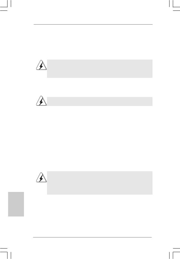
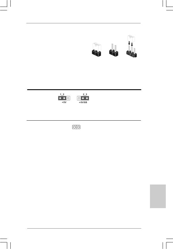
2.6 Jumpers Setup
The illustration shows how jumpers are |
|
|
||
setup. When the jumper cap is placed on |
|
|
||
pins, the jumper is “Short”. If no jumper cap |
|
|
||
is placed on pins, the jumper is “Open”. The |
|
|
||
illustration shows a 3-pin jumper whose pin1 |
Short |
Open |
||
and pin2 are “Short” when jumper cap is |
||||
|
|
|||
placed on these 2 pins. |
|
|
|
|
Jumper |
Setting |
|
Description |
|
PS2_USB_PWR1 |
|
|
Short pin2, pin3 to enable |
|
(see p.2 No. 1) |
|
|
+5VSB (standby) for PS/2 |
|
|
|
|
or USB wake up events. |
|
Note: To select +5VSB, it requires 2 Amp and higher standby current provided by power supply.
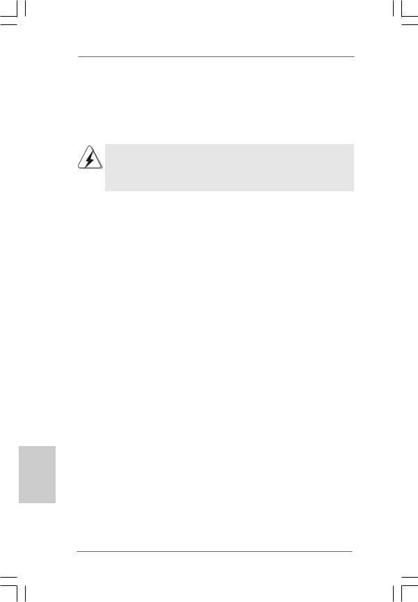
Clear CMOS
(CLRCMOS1, 2-pin jumper)
(see p.2 No. 6)
2-pin jumper
Note: CLRCMOS1 allows you to clear the data in CMOS. The data in CMOS includes system setup information such as system password, date, time, and system setup parameters. To clear and reset the system parameters to default setup, please turn off the computer and unplug the power cord from the power supply. After waiting for 15 seconds, use a jumper cap to short 2 pins on CLRCMOS1 for 5 seconds.
English
1 3
ASRock A330ION Motherboard
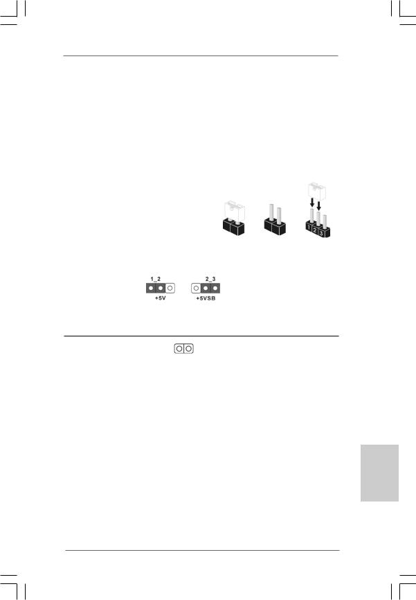
2.7 Onboard Headers and Connectors
Onboard headers and connectors are NOT jumpers. Do NOT place jumper caps over these headers and connectors. Placing jumper caps over the headers and connectors will cause permanent damage of the motherboard!
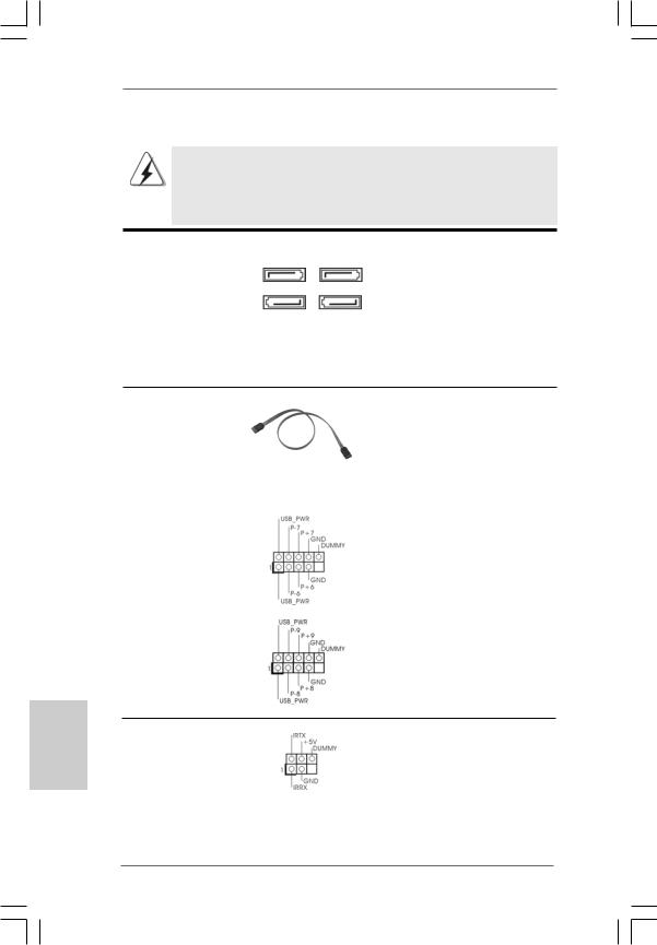
Serial ATAII Connectors
(SATAII_1: see p.2,No. 15) (SATAII_2: see p.2,No. 16) (SATAII_3: see p.2,No. 14) (SATAII_4: see p.2,No. 10)
SATAII_2 SATAII_4
SATAII_1 SATAII_3
These Serial ATAII (SATAII) connectors support SATAII or SATA hard disk for internal storage devices. The current SATAII interface allows up to 3.0 Gb/s data transfer rate.
Serial ATA (SATA) |
Either end of the SATA data cable |
Data Cable |
can be connected to the SATA / |
(Optional) |
SATAII hard disk or the SATAII |
|
connector on the motherboard. |
|
|
USB 2.0 Headers |
Besides four default USB 2.0 |
(9-pin USB6_7) |
ports on the I/O panel, there are |
(see p.2 No. 24) |
two USB 2.0 headers on this |
|
motherboard. Each USB 2.0 |
|
header can support two USB |
|
2.0 ports. |
(9-pin USB8_9) |
|
(see p.2 No. 22) |
|
English
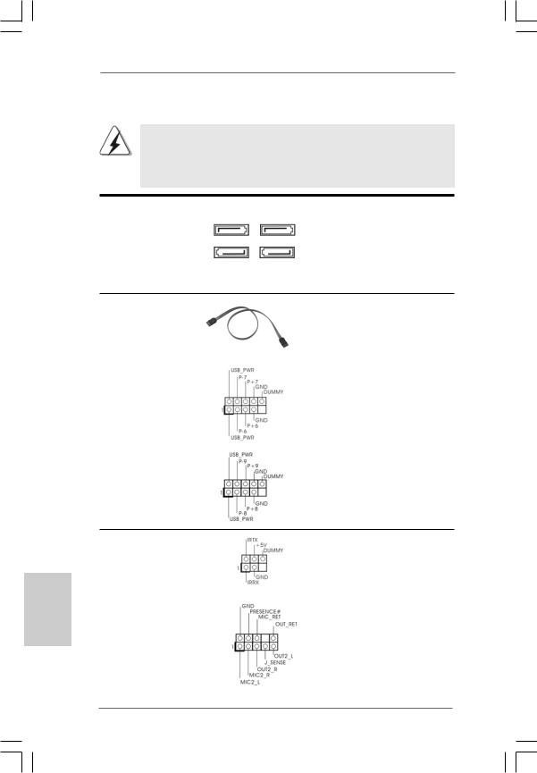
Infrared Module Header |
This header supports an |
(5-pin IR1) |
optional wireless transmitting |
(see p.2 No. 12) |
and receiving infrared module. |
|
|
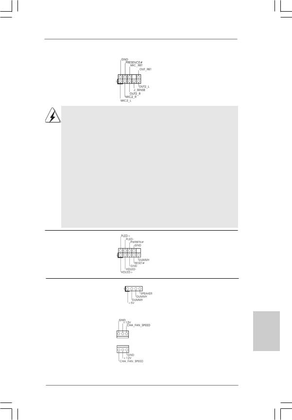
Front Panel Audio Header |
This is an interface for front |
(9-pin HD_AUDIO1) |
panel audio cable that allows |
(see p.2 No. 19) |
convenient connection and |
|
control of audio devices. |
1 4
ASRock A330ION Motherboard
1.High Definition Audio supports Jack Sensing, but the panel wire on the chassis must support HDA to function correctly. Please follow the instruction in our manual and chassis manual to install your system.
2.If you use AC’97 audio panel, please install it to the front panel audio header as below:
A.Connect Mic_IN (MIC) to MIC2_L.
B.Connect Audio_R (RIN) to OUT2_R and Audio_L (LIN) to OUT2_L.
C.Connect Ground (GND) to Ground (GND).
D.MIC_RET and OUT_RET are for HD audio panel only. You don’t need to connect them for AC’97 audio panel.
E.Enter BIOS Setup Utility. Enter Advanced Settings, and then select Chipset Configuration. Set the Front Panel Control option from [Auto] to [Enabled].
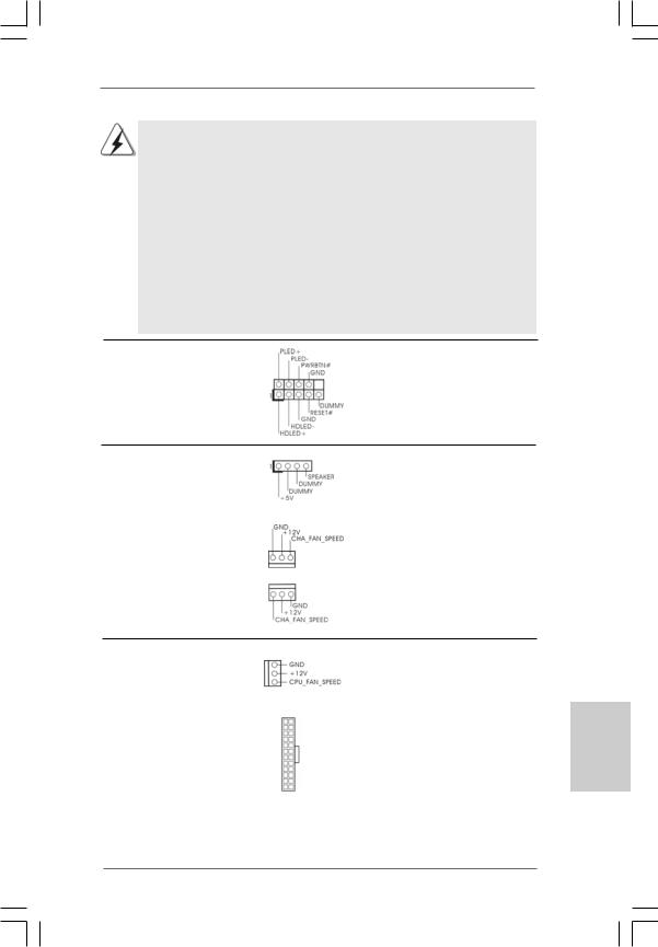
System Panel Header |
This header accommodates |
(9-pin PANEL1) |
several system front panel |
(see p.2 No. 11) |
functions. |
Chassis Speaker Header |
Please connect the chassis |
(4-pin SPEAKER 1) |
speaker to this header. |
(see p.2 No. 13) |
|
|
|
Chassis Fan Connectors |
Please connect a chassis fan |
(3-pin CHA_FAN1) |
cable to this connector and |
(see p.2 No. 2) |
match the black wire to the |
|
ground pin. |
(3-pin CHA_FAN2) |
|
(see p.2 No. 9) |
|
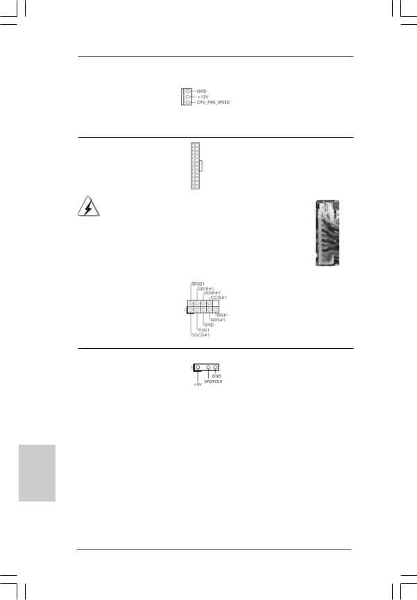
CPU Fan Connector |
|
|
Please connect a CPU fan cable |
(3-pin CPU_FAN1) |
|
|
to this connector and match |
(see p.2 No. 4) |
|
|
the black wire to the ground pin. |
|
|
|
|
ATX Power Connector |
12 |
24 |
Please connect an ATX power |
(24-pin ATXPWR1) |
|
|
supply to this connector. |
(see p.2, No. 8) |
|
|
|
|
1 |
13 |
|
1 5
English
ASRock A330ION Motherboard
|
Though this motherboard provides 24-pin ATX power connector, |
12 |
24 |
|
|
it can still work if you adopt a traditional 20-pin ATX power supply. |
|
|
|
|
To use the 20-pin ATX power supply, please plug your power |
|
|
|
|
supply along with Pin 1 and Pin 13. |
|
|
|
|
|
20-PinATX Power Supply Installation |
1 |
13 |
|
|
|
||
|
|
|||
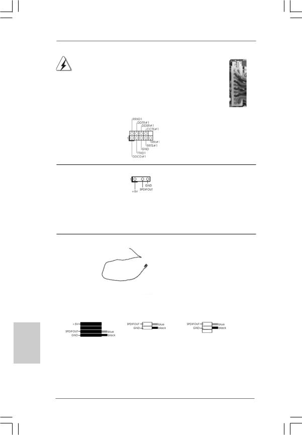
Serial port Header |
This COM1 header supports a |
|||
(9-pin COM1) |
serial port module. |
|
||
(see p.2 No.18) |
|
|
|
|
HDMI_SPDIFHeader |
HDMI_SPDIF header, providing |
(3-pin HDMI_SPDIF1) |
SPDIF audio output to HDMI VGA |
(see p.2 No. 20) |
card, allows the system to |
|
connect HDMI Digital TV/ |
|
projector/LCD devices. Please |
|
connect the HDMI_SPDIF |
|
connector of HDMI VGA card to |
|
this header. |
HDMI_SPDIFCable
(Optional) C
B
A
Please connect the black end (A) of HDMI_SPDIF cable to the HDMI_SPDIF header on the motherboard. Then connect the white end (B or C) of HDMI_SPDIF cable to the HDMI_SPDIF connector of HDMI VGA card.
A. black end |
B. white end (2-pin) |
C. white end (3-pin) |
English
1 6
ASRock A330ION Motherboard
12 24
n 1 |
13 |
2.8Serial ATA (SATA) / Serial ATAII (SATAII) Hard Disks
Installation
This motherboard adopts NVIDIA® MCP7A-ION chipset that supports Serial ATA (SATA) / Serial ATAII (SATAII) hard disks and RAID functions. You may install SATA / SATAII hard disks on this motherboard for internal storage devices. This section will guide you to install the SATA / SATAII hard disks.
STEP 1: Install the SATA / SATAII hard disks into the drive bays of your chassis. STEP 2: Connect the SATA power cable to the SATA / SATAII hard disk.
STEP 3: Connect one end of the SATA data cable to the motherboard’s SATAII connector.
STEP 4: Connect the other end of the SATA data cable to the SATA / SATAII hard disk.
2.9 Hot Plug and Hot Swap Functions for SATA / SATAII HDDs
This motherboard supports Hot Plug and Hot Swap functions for SATA / SATAII in RAID / AHCI mode. NVIDIA® MCP7A-ION chipset provides hardware support for Advanced Host controller Interface (AHCI), a new programming interface for SATA host controllers developed thru a joint industry effort.
NOTE
What is Hot Plug Function?
If the SATA / SATAII HDDs are NOT set for RAID configuration, it is called “Hot Plug” for the action to insert and remove the SATA / SATAII HDDs while the system is still power-on and in working condition.
However, please note that it cannot perform Hot Plug if the OS has been installed into the SATA / SATAII HDD.
What is Hot Swap Function?
If SATA / SATAII HDDs are built as RAID1 then it is called “Hot Swap” for |
|
the action to insert and remove the SATA / SATAII HDDs while the system |
|
is still power-on and in working condition. |
English |
AHCI mode only. |
|
For Powered eSATA function, Hot Plug function is supported in RAID / |
|
1 7
ASRock A330ION Motherboard
English
2.10 Driver Installation Guide
To install the drivers to your system, please insert the support CD to your optical drive first. Then, the drivers compatible to your system can be auto-detected and listed on the support CD driver page. Please follow the order from up to bottom side to install those required drivers. Therefore, the drivers you install can work properly.
2.11 Installing Windows® 7 / 7 64-bit / VistaTM /
VistaTM 64-bit / XP / XP 64-bit Without RAID Functions
If you want to install Windows® 7 / 7 64-bit / VistaTM / VistaTM 64-bit / XP / XP 64-bit OS on your SATA / SATAII HDDs without RAID functions, please follow below procedures according to the OS you install.
2.11.1Installing Windows® XP / XP 64-bit Without RAID
Functions
If you want to install Windows® XP / XP 64-bit OS on your SATA / SATAII HDDs without RAID functions, please follow below steps.
AHCI mode is not supported under Windows® XP / XP 64-bit OS.
Using SATA / SATAII HDDs in IDE Mode
STEP 1: Set up BIOS.
A.Enter BIOS SETUP UTILITY  Advanced screen
  Storage Configuration.
B.Set the option “SATA Operation Mode” to [IDE].
STEP 2: Install Windows® XP / XP 64-bit OS on your system.
2.11.2Installing Windows® 7 / 7 64-bit / VistaTM /
VistaTM 64-bit Without RAID Functions
If you want to install Windows® 7 / 7 64-bit / VistaTM / VistaTM 64-bit OS on your SATA / SATAII HDDs without RAID functions, please follow below steps.
Using SATA / SATAII HDDs in AHCI Mode
STEP 1: Set Up BIOS.
A.Enter BIOS SETUP UTILITY  Advanced screen
  Storage Configuration.
B.Set the option “SATA Operation Mode” to [AHCI].
STEP 2: Install Windows® 7 / 7 64-bit / VistaTM / VistaTM 64-bit OS on your system.
1 8
ASRock A330ION Motherboard
Using SATA / SATAII HDDs in IDE Mode
STEP 1: Set up BIOS.
A.Enter BIOS SETUP UTILITY  Advanced screen
  Storage Configuration.
B.Set the option “SATA Operation Mode” to [IDE].
STEP 2: Install Windows® 7 / 7 64-bit / VistaTM / VistaTM 64-bit OS on your system.
2.12 Installing Windows® 7 / 7 64-bit / VistaTM / VistaTM 64-bit With RAID Functions
If you want to install Windows® 7 / 7 64-bit / VistaTM / VistaTM 64-bit OS on your SATA / SATAII HDDs with RAID functions, please follow below procedures according to the OS you install.
RAID mode is not supported under Windows® XP / XP 64-bit OS.
STEP 1: Set Up BIOS.
A.Enter BIOS SETUP UTILITY Advanced screen
  Storage Configuration.
B.Set the “SATA Operation Mode” option to [RAID].
STEP 2: Use “RAID Installation Guide” to set RAID configuration.
Before you start to configure RAID function, you need to check the RAID installation guide in the Support CD for proper configuration. Please refer to the BIOS RAID installation guide part of the document in the following path in the Support CD:
.. \ RAID Installation Guide
STEP 3: Install Windows® 7 / 7 64-bit / VistaTM / VistaTM 64-bit OS on your system.
Insert the Windows® 7 / 7 64-bit / VistaTM / VistaTM 64-bit optical disk into the optical drive to boot your system, and follow the instruction to install Windows® 7 / 7 64-bit / VistaTM / VistaTM 64-bit OS on your system. When you see “Where do you want to install Windows?” page, please insert the ASRock Support CD into your optical drive, and click the “Load Driver” button on the left on the bottom to load the NVIDIA® RAID drivers. NVIDIA® RAID drivers are in the following path in our Support CD:
.. \ I386 (For Windows® 7 / VistaTM OS)
.. \ AMD64 (For Windows® 7 64-bit / VistaTM 64-bit OS)
After that, please insert Windows® 7 / 7 64-bit / VistaTM / VistaTM 64-bit optical disk into the optical drive again to continue the installation.
NOTE. If you install Windows® 7 / 7 64-bit / VistaTM / VistaTM 64-bit on IDE HDDs and want to manage (create, convert, delete, or rebuild) RAID functions on SATA / SATAII HDDs, you still need to set up “SATA Operation Mode” to [RAID] in BIOS first. Then, please set the RAID configuration by using the Windows RAID installation guide in the following path in the Support CD:
.. \ RAID Installation Guide
1 9
English
ASRock A330ION Motherboard
2.13 Untied Overclocking Technology
This motherboard supports Untied Overclocking Technology, which means during overclocking, FSB enjoys better margin due to fixed PCI bus. Before you enable Untied Overclocking function, please enter “Overclock Mode” option of BIOS setup to set the selection from [Auto] to [Manual]. Therefore, CPU FSB is untied during overclocking, but PCI buse is in the fixed mode so that FSB can operate under a more stable overclocking environment.
Please refer to the warning on page 8 for the possible overclocking risk before you apply Untied Overclocking Technology.
3. BIOS Information
The Flash Memory on the motherboard stores BIOS Setup Utility. When you start up the computer, please press <F2> during the Power-On-Self-Test (POST) to enter BIOS Setup utility; otherwise, POST continues with its test routines. If you wish to enter BIOS Setup after POST, please restart the system by pressing <Ctl> + <Alt> + <Delete>, or pressing the reset button on the system chassis. The BIOS Setup program is designed to be user-friendly. It is a menu-driven program, which allows you to scroll through its various sub-menus and to select among the predetermined choices. For the detailed information about BIOS Setup, please refer to the User Manual (PDF file) contained in the Support CD.
English
4. Software Support CD information
This motherboard supports various Microsoft® Windows® operating systems: 7 /
7 64-bit / VistaTM / VistaTM 64-bit / XP / XP 64-bit. The Support CD that came with the motherboard contains necessary drivers and useful utilities that will enhance motherboard features. To begin using the Support CD, insert the CD into your CDROM drive. It will display the Main Menu automatically if “AUTORUN” is enabled in your computer. If the Main Menu does not appear automatically, locate and doubleclick on the file “ASSETUP.EXE” from the BIN folder in the Support CD to display the menus.
2 0
ASRock A330ION Motherboard
1. Einführung
Wir danken Ihnen für den Kauf des ASRock A330ION Motherboard, ein zuverlässiges Produkt, welches unter den ständigen, strengen Qualitätskontrollen von ASRock gefertigt wurde. Es bietet Ihnen exzellente Leistung und robustes Design, gemäß der Verpflichtung von ASRock zu Qualität und Halbarkeit.
Diese Schnellinstallationsanleitung führt in das Motherboard und die schrittweise Installation ein. Details über das Motherboard finden Sie in der Bedienungsanleitung auf der Support-CD.
Da sich Motherboard-Spezifikationen und BIOS-Software verändern können, kann der Inhalt dieses Handbuches ebenfalls jederzeit geändert werden. Für den Fall, dass sich Änderungen an diesem Handbuch ergeben, wird eine neue Version auf der ASRock-Website, ohne weitere Ankündigung, verfügbar sein. Die neuesten Grafikkarten und unterstützten CPUs sind auch auf der ASRock-Website aufgelistet.
ASRock-Website: http://www.asrock.com
Wenn Sie technische Unterstützung zu Ihrem Motherboard oder spezifische Informationen zu Ihrem Modell benötigen, besuchen Sie bitte unsere Webseite:
www.asrock.com/support/index.asp
1.1 Kartoninhalt
ASRock A330ION Motherboard
(Mini-ITX-Formfaktor: 17.0 cm x 17.1 cm; 6.7 Zoll x 6.7 Zoll) Ein mitgelieferter Intel® Dual-Core-AtomTM-Prozessor 330 ASRock A330ION Schnellinstallationsanleitung
ASRock A330ION_ Support-CD
Zwei Seriell-ATA- (SATA) Datenkabel (Option)
Ein Serial ATA (SATA) -Festplattenstromkabel (optional) Ein I/O Shield
Deutsch
2 1
ASRock A330ION Motherboard

1.2Spezifikationen
Deutsch
2 2
Plattform |
- Mini-ITX-Formfaktor: 17.0 cm x 17.1 cm; 6.7 Zoll x 6.7 Zoll |
|
- Alle Feste Kondensatordesign (100% in Japan gefertigte, |
|
erstklassige leitfähige Polymer-Kondensatoren) |
CPU |
- Intel® Dual-Core AtomTM-Prozessor 330 (1.6 GHz) |
|
- Unterstützt Hyper-Threading-Technologie |
|
(siehe VORSICHT 1) |
|
- Unterstützt Untied-Übertaktungstechnologie |
|
(siehe VORSICHT 2) |
|
- Unterstützt EM64T |
Chipsatz |
-NVIDIA® MCP7A-ION |
Speicher |
- Unterstützung von Dual-Kanal-Speichertechnologie |
|
(siehe VORSICHT 3) |
|
- 2 x Steckplätze für DDR3 |
|
- Unterstützt DDR3 1066/800 non-ECC, ungepufferter Speicher |
|
- Max. Kapazität des Systemspeichers: 4GB |
|
(siehe VORSICHT 4) |
Erweiterungs- |
- 1 x PCI Express 2.0 x16-Steckplätze |
steckplätze |
|
Onboard-VGA |
- Integrierte NVIDIA® GeForce 9 Serie |
|
- DX10 VGA, Pixel Shader 4.0 |
|
- Maximal gemeinsam genutzter Speicher 512MB |
|
(siehe VORSICHT 5) |
|
- Drei VGA-Ausgangsoptionen: D-Sub, DVI-D sowie HDMI |
|
- Unterstützt HDMI mit einer maximalen Auflösung von |
|
1920 x 1200 (1080p) |
|
- Unterstützt Dual-Link-DVI mit einer maximalen Auflösung von |
|
bis zu 2560 x 1600 bei 75 Hz |
|
- Unterstützt D-Sub mit einer maximalen Auflösung von |
|
1920 x 1440 bei 75 Hz |
|
- unterstützt HDCP Funktion |
|
- Unterstutzt 1080p Blu-ray (BD) / HD-DVD-Wiedergabe |
Audio |
- 7.1 CH HD Audio (VIA® VT2020 Audio Codec) |
LAN |
- Gigabit LAN 10/100/1000 Mb/s |
|
- Giga PHY RTL8211CL |
|
- Unterstützt Wake-On-LAN |
E/A-Anschlüsse |
I/O Panel |
an der |
- 1 x PS/2-Tastaturanschluss |
Rückseite |
- 1 x VGA/D-Sub port |
|
- 1 x VGA/DVI-D port |
ASRock A330ION Motherboard
|
- 1 x HDMI port |
|
- 1 x optischer SPDIF-Ausgang |
|
- 4 x Standard-USB 2.0-Anschlüsse |
|
- 2 x eSATAII/USB-Anschluss mit Stromversorgung |
|
- 1 x RJ-45 LAN Port mit LED (ACT/LINK LED und SPEED LED) |
|
- HD Audiobuchse: Lautsprecher hinten / Mitte/Bass / |
|
Audioeingang/ Lautsprecher vorne / Mikrofon |
|
(siehe VORSICHT 6) |
Anschlüsse |
- 4 x Serial ATAII 3,0 GB/s-Anschlüsse, unterstützen RAID- |
|
(RAID 0 und RAID 1), NCQ, AHCI und “Hot Plug” Funktionen |
|
(siehe VORSICHT 7) |
|
- 1 x Infrarot-Modul-Header |
|
- 1 x COM-Anschluss-Header |
|
- 1 x HDMI_SPDIF-Anschluss |
|
- CPU/Gehäuse-Lüfteranschluss |
|
- 24-pin ATX-Netz-Header |
|
- Anschluss für Audio auf der Gehäusevorderseite |
|
- 2 x USB 2.0 Buchse (unterstützt 4 USB 2.0 Ports) |
|
(siehe VORSICHT 8) |
BIOS |
- 8Mb AMI BIOS |
|
- AMI legal BIOS mit Unterstützung für “Plug and Play” |
|
- ACPI 1.1-Weckfunktionen |
|
- JumperFree-Modus |
|
- SMBIOS 2.3.1 |
|
- VCCM Stromspannung Multianpassung |
|
- Unterstützt Smart BIOS |
Support-CD |
- Treiber, Dienstprogramme, Antivirussoftware |
|
(Probeversion), ASRock-Software-Suite (CyberLink |
|
DVD Suite und Creative Sound Blaster X-Fi MB) (OEMund |
|
Testversion) |
Einzigartige |
- ASRock OC Tuner (siehe VORSICHT 9) |
Eigenschaft |
- Sofortstart |
|
- ASRock Instant Flash (siehe VORSICHT 10) |
|
- ASRock OC DNA (siehe VORSICHT 11) |
|
- Hybrid Booster: |
|
- Schrittloser CPU-Frequenz-Kontrolle |
|
(siehe VORSICHT 12) |
|
- ASRock U-COP (siehe VORSICHT 13) |
|
- Boot Failure Guard (B.F.G. – Systemstartfehlerschutz) |
|
- Gute Nacht-LED |
Hardware Monitor - Überwachung der CPU-Temperatur - Motherboardtemperaturerkennung
2 3
Deutsch
ASRock A330ION Motherboard

Deutsch
|
|
- Drehzahlmessung für CPU-Lüfter |
|
|
|
- Drehzahlmessung für Gehäuselüfter |
|
|
|
- Spannungsüberwachung: +12V, +5V, +3.3V, Vcore |
|
|
Betriebssysteme |
- Unterstützt Microsoft® Windows® 7 / 7 64-Bit / VistaTM / |
|
|
|
VistaTM 64-Bit / XP / XP 64-Bit |
|
|
Zertifizierungen |
- FCC, CE, WHQL |
|
-Gemäß Ökodesign-Richtlinie (EuP) (Stromversorgung gemäß Ökodesign-Richtlinie (EuP) erforderlich) (siehe VORSICHT 14)
*Für die ausführliche Produktinformation, besuchen Sie bitte unsere Website: http://www.asrock.com
WARNUNG
Beachten Sie bitte, dass Overclocking, einschließlich der Einstellung im BIOS, Anwenden der Untied Overclocking-Technologie oder Verwenden von Overclocking-Werkzeugen von Dritten, mit einem gewissen Risiko behaftet ist. Overclocking kann sich nachteilig auf die Stabilität Ihres Systems auswirken oder sogar Komponenten und Geräte Ihres Systems beschädigen. Es geschieht dann auf eigene Gefahr und auf Ihre Kosten. Wir übernehmen keine Verantwortung für mögliche Schäden, die aufgrund von Overclocking verursacht wurden.
VORSICHT!
1.Die Einstellung der “Hyper-Threading Technology”, finden Sie auf Seite 33 des auf der Support-CD enthaltenen Benutzerhandbuches beschrieben.
2.Dieses Motherboard unterstützt die Untied-Übertaktungstechnologie. Unter “Entkoppelte Übertaktungstechnologie” auf Seite 20 finden Sie detaillierte Informationen.
3.Dieses Motherboard unterstützt Dual-Kanal-Speichertechnologie. Vor Implementierung der Dual-Kanal-Speichertechnologie müssen Sie die Installationsanleitung für die Speichermodule auf Seite 11 zwecks richtiger Installation gelesen haben.
4.Aufgrund von Chipset-Einschränkungen könnte unter Windows® OS die für das System reservierte Speichergröße unterhalb von 4 GB liegen.
5.Die Maximalspeichergröße ist von den Chipshändler definiert und umgetauscht. Bitte überprüfen Sie Intel® website für die neuliche Information.
6.Der Mikrofoneingang dieses Motherboards unterstützt Stereound MonoModi. Der Audioausgang dieses Motherboards unterstützt 2-Kanal-, 4- Kanal-, 6-Kanal- und 8-Kanal-Modi. Stellen Sie die richtige Verbindung anhand der Tabelle auf Seite 3 her.
7.Vor Installation der SATAII-Festplatte an den SATAII-Anschluss lesen Sie bitte “Setup-Anleitung für SATAII-Festplatte” auf Seite 21 der “Bedienungsanleitung” auf der Support-CD, um Ihre SATAII-Festplatte dem SATAII-Modus anzugleichen. Sie können die SATA-Festplatte auch direkt mit dem SATAII-Anschluss verbinden.
2 4
ASRock A330ION Motherboard

8.Das Power Management für USB 2.0 arbeitet unter Microsoft® Windows® 7 64-Bit / 7 / VistaTM 64-Bit / VistaTM / XP 64-Bit / XP SP1 oder SP2 einwandfrei.
9.Es ist ein benutzerfreundlicher ASRock Übertaktenswerkzeug, das erlaubt, dass Sie Ihr System durch den Hardware-Monitor Funktion zu überblicken und Ihre Hardware-Geräte übertakten, um die beste Systemleistung unter der Windows® Umgebung zu erreichen. Besuchen Sie bitte unsere Website für die Operationsverfahren von ASRock OC Tuner. ASRock-Website: http://www.asrock.com
10.ASRock Instant Flash ist ein im Flash-ROM eingebettetes BIOS-Flash- Programm. Mithilfe dieses praktischen BIOS-Aktualisierungswerkzeugs können Sie das System-BIOS aktualisieren, ohne dafür zuerst Betriebssysteme wie MS-DOS oder Windows® aufrufen zu müssen. Mit diesem Programm bekommen Sie durch Drücken der <F6>-Taste während des POST-Vorgangs oder durch Drücken der <F2>-Taste im BIOS-Setup-Menü Zugang zu ASRock Instant Flash. Sie brauchen dieses Werkzeug einfach nur zu starten und die neue BIOS-Datei auf Ihrem USB-Flash-Laufwerk, Diskettenlaufwerk oder der Festplatte zu speichern, und schon können Sie Ihr BIOS mit nur wenigen Klickvorgängen ohne Bereitstellung einer zusätzlichen Diskette oder eines anderen komplizierten Flash-Programms aktualisieren. Achten Sie darauf, dass das USB-Flash-Laufwerk oder die Festplatte das Dateisystem FAT32/16/12 benutzen muss.
11.Allein der Name – OC DNA* – beschreibt es wörtlich, was die Software zu leisten vermag. OC DNA ist ein von ASRock exklusiv entwickeltes Dienstprogramm, das Nutzern eine bequeme Möglichkeit bietet, Übertaktungseinstellungen aufzuzeichnen und sie Anderen mitzuteilen. Es hilft Ihnen, Ihre Übertaktungsaufzeichnung im Betriebssystem zu speichern und vereinfacht den komplizierten Aufzeichnungsvorgang von Übertaktungseinstellungen. Mit OC DNA können Sie Ihre Übertaktungseinstellungen als Profil abspeichern und Ihren Freunden zugänglich machen! Ihre Freunde können dann das Übertaktungsprofil auf ihren eigenen Systemen laden, um dieselben Übertaktungseinstellungen. Mit OC DNA können Sie Ihre Übertaktungseinstellungen als Profil abspeichern und Ihren Freunden zugänglich machen! Ihre Freunde können dann das Übertaktungsprofil auf ihren eigenen Systemen laden, um dieselben Übertaktungseinstellungen wie Sie zu erhalten! Beachten Sie bitte, dass das Übertaktungsprofil nur bei einem identischen Motherboard gemeinsam genutzt und funktionsfähig gemacht werden kann. Übertaktungseinstellungen wie Sie zu erhalten! Beachten Sie bitte, dass das Übertaktungsprofil nur bei einem identischen Motherboard gemeinsam genutzt und funktionsfähig gemacht werden kann.
12.Obwohl dieses Motherboard stufenlose Steuerung bietet, wird Overclocking nicht empfohlen. Frequenzen, die von den empfohlenen CPU-Busfrequenzen abweichen, können Instabilität des Systems verursachen oder die CPU beschädigen.
Deutsch
2 5
ASRock A330ION Motherboard

13.Wird eine Überhitzung der CPU registriert, führt das System einen automatischen Shutdown durch. Bevor Sie das System neu starten, prüfen Sie bitte, ob der CPU-Lüfter am Motherboard richtig funktioniert, und stecken Sie bitte den Stromkabelstecker aus und dann wieder ein. Um die Wärmeableitung zu verbessern, bitte nicht vergessen, etwas Wärmeleitpaste zwischen CPU und Kühlkörper zu sprühen.
14.EuP steht für Energy Using Product und kennzeichnet die ÖkodesignRichtlinie, die von der Europäischen Gemeinschaft zur Festlegung des Energieverbrauchs von vollständigen Systemen in Kraft gesetzt wurde. Gemäß dieser Ökodesign-Richtlinie (EuP) muss der gesamte Netzstromverbrauch von vollständigen Systemen unter 1,00 Watt liegen, wenn sie ausgeschaltet sind. Um dem EuP-Standard zu entsprechen, sind ein EuP-fähiges Motherboard und eine EuP-fähige Stromversorgung erforderlich. Gemäß einer Empfehlung von Intel muss eine EuP-fähige Stromversorgung dem Standard entsprechen, was bedeutet, dass bei einem Stromverbrauch von 100 mA die 5-Volt-Standby-Energieeffizienz höher als 50% sein sollte. Für die Wahl einer EuP-fähigen Stromversorgung empfehlen wir Ihnen, weitere Details beim Hersteller der Stromversorgung abzufragen.
Deutsch
2 6
ASRock A330ION Motherboard
1.3 Einstellung der Jumper
Die Abbildung verdeutlicht, wie Jumper gesetzt werden. Werden Pins durch Jumperkappen verdeckt, ist der Jumper “Gebrückt”. Werden keine Pins durch Jumperkappen verdeckt, ist der Jumper “Offen”. Die Abbildung zeigt einen 3-Pin Jumper dessen Pin1 und Pin2 “Gebrückt” sind, bzw. es befindet sich eine JumperKappe auf diesen beiden Pins.
Einstellun Beschreibung
Überbrücken Sie Pin2, Pin3, um +5VSB (Standby) zu setzen und die PS/2 oder USBWeckfunktionen zu aktivieren.
Hinweis: Um +5VSB nutzen zu können, muss das Netzteil auf dieser Leitung 2A oder mehr leisten können.
CMOS löschen
(CLRCMOS1, 2-Pin jumper) (siehe S.2 - No. 6)
2-Pin jumper
Hinweis: Mit CLRCMOS1 können Sie die Daten im CMOS löschen. Die CMOS Daten beinhalten die Systeminformationen wie Systemkennwort, Datum, Zeit und System-Setupeinstellungen. Um die Einstellungen zu löschen und Default-Werte wiederherzustellen, schalten Sie den Computer aus, ziehen Sie den Netzstecker und überbrücken Sie 2-pin von CLRCMOS1 mithilfe des Jumpers für 5 Sekunden.
Deutsch
2 7
ASRock A330ION Motherboard
Deutsch
1.4 Integrierte Header und Anschlüsse
Integrierte Header und Anschlüsse sind KEINE Jumper. Setzen Sie KEINE Jumperkappen auf diese Header und Anschlüsse. Wenn Sie Jumperkappen auf Header und Anschlüsse setzen, wird das Motherboard unreparierbar beschädigt!
Seriell-ATAII-Anschlüsse
(SATAII_1: siehe S.2, Punkt 15) (SATAII_2: siehe S.2, Punkt 16) (SATAII_3: siehe S.2, Punkt 14) (SATAII_4: siehe S.2, Punkt 10)
SATAII_2 SATAII_4
SATAII_1 SATAII_3
Diese vier Serial ATA (SATA II) -Anschlüsse unterstützen interne SATAoder SATA II-Festplatten. Die aktuelle SATAII-Schnittstelle ermöglicht eine
Datenübertragungsrate bis 3,0 Gb/s.
Serial ATA- (SATA-) |
Sie können beide Enden des |
|
Datenkabel |
SATA-Datenkabels entweder |
|
(Option) |
mit der SATA / SATAII- |
|
|
|
Festplatte oder |
|
|
dem SATAII-Anschluss am |
|
|
Mainboard verbinden. |
|
|
|
USB 2.0-Header |
Zusätzlich zu den vier |
|
(9-pol. USB6_7) |
üblichen USB 2.0-Ports an den |
|
(siehe S.2 - No. 24) |
I/O-Anschlüssen befinden sich |
|
|
|
zwei USB 2.0-Anschlussleisten |
|
|
am Motherboard. Pro USB 2.0- |
|
|
Anschlussleiste werden zwei |
(9-pol. USB8_9) |
USB 2.0-Ports unterstützt. |
|
(siehe S.2 - No. 22) |
|
|
Infrarot-Modul-Header |
Dieser Header unterstützt ein |
(5-pin IR1) |
optionales, drahtloses Sende- |
(siehe S.2 - No. 12) |
und Empfangs-Infrarotmodul. |
2 8
ASRock A330ION Motherboard
Anschluss für Audio auf |
Dieses Interface zu einem |
derGehäusevorderseite |
Audio-Panel auf der Vorderseite |
(9-Pin HD_AUDIO1) |
Ihres Gehäuses, ermöglicht |
(siehe S.2 - No. 19) |
Ihnen eine bequeme |
|
Anschlussmöglichkeit und |
|
Kontrolle über Audio-Geräte. |
1.High Definition Audio unterstützt Jack Sensing (automatische Erkennung falsch angeschlossener Geräte), wobei jedoch die Bildschirmverdrahtung am Gehäuse HDA unterstützen muss, um richtig zu funktionieren.
Beachten Sie bei der Installation im System die Anweisungen in unserem Handbuch und im Gehäusehandbuch.
2.Wenn Sie die AC’97-Audioleiste verwenden, installieren Sie diese wie nachstehend beschrieben an der Front-Audioanschlussleiste:
A.Schließen Sie Mic_IN (MIC) an MIC2_L an.
B.Schließen Sie Audio_R (RIN) an OUT2_R und Audio_L (LIN) an OUT2_L an.
C.Schließen Sie Ground (GND) an Ground (GND) an.
D.MIC_RET und OUT_RET sind nur für den HD-Audioanschluss gedacht. Diese Anschlüsse müssen nicht an die AC’97-Audioleiste angeschlossen werden.
E.Rufen Sie das BIOS-Setup-Dienstprogramm auf. Wechseln Sie zu Erweiterte Einstellungen und wählen Sie Chipset-Konfiguration. Setzen Sie die Option Frontleistenkontrolle von [Automatisch] auf [Aktiviert].
System Panel-Header |
Dieser Header unterstützt |
(9-pin PANEL1) |
mehrere Funktion der |
(siehe S.2 - No. 11) |
Systemvorderseite. |
Gehäuselautsprecher-Header |
Schließen Sie den |
(4-pin SPEAKER1) |
Gehäuselautsprecher an |
(siehe S.2 - No. 13) |
diesen Header an. |
|
|
Gehäuselüfteranschluss |
Verbinden Sie das |
(3-pin CHA_FAN1) |
Gehäuselüfterkabel mit diesem |
(siehe S.2 - No. 2) |
Anschluss und passen Sie den |
|
schwarzen Draht dem |
(3-pin CHA_FAN2) |
Erdungsstift an. |
(siehe S.2 - No. 9) |
|
2 9
Deutsch
ASRock A330ION Motherboard
CPU-Lüfteranschluss |
Verbinden Sie das CPU - |
(3-pin CPU_FAN1) |
Lüfterkabel mit diesem |
(siehe S.2 - No. 4) |
Anschluss und passen Sie den |
|
schwarzen Draht dem |
|
Erdungsstift an. |
ATX-Netz-Header |
12 |
24 |
|
|
(24-pin ATXPWR1)
(siehe S.2 - No. 8)
1 13
Verbinden Sie die ATXStromversorgung mit diesem Header.
|
Obwohl dieses Motherboard einen 24-pol. ATX-Stromanschluss 12 |
24 |
|
||
|
bietet, kann es auch mit einem modifizierten traditionellen 20-pol. |
|
|
||
|
ATX-Netzteil verwendet werden. Um ein 20-pol. ATX-Netzteil zu |
|
|
|
|
|
verwenden, stecken Sie den Stecker mit Pin 1 und Pin 13 ein. |
|
|
|
|
|
|
Installation eines 20-pol. ATX-Netzteils |
1 |
13 |
|
|
|
|
|
||
|
|
|
|
|
|
|
|
|
|
||
COM-Anschluss-Header |
Dieser COM-Anschluss- |
|
|
||
(9-pin COM1) |
Header wird verwendet, um |
|
|||
(siehe S.2 - No. 18) |
ein COM-Anschlussmodul zu |
|
|||
|
|
unterstützen. |
|
|
|
Deutsch
HDMI_SPDIF-Anschluss |
Der HDMI_SPDIF-Anschluss |
(HDMI_SPDIF1, dreipolig) |
stellt einen SPDIF- |
(siehe S.2 - No. 20) |
Audioausgang für eine HDMI- |
|
VGA-Karte zur Verfügung und |
|
ermöglicht den Anschluss von |
|
HDMI-Digitalgeräten wie |
|
Fernsehgeräten, Projektoren, |
|
LCD-Geräten an das System. |
|
Bitte verbinden Sie den |
|
HDMI_SPDIF-Anschluss der |
|
HDMI-VGA-Karte mit diesem |
|
Anschluss. |
3 0
ASRock A330ION Motherboard
 Loading...