

Page 1

aprilia part# 8104588
ATLANTIC 500
use+maintenancebook
Page 2

© 2003 aprilia s.p.a. - Noale (VE)
First edizion: february 2003
Reprint:
Produced and printed by:
C.L.D. s.r.l. Technical manuals division
via D. Alighieri, 37/A - 56012 Fornacette (Pisa)
Tel. +39 - (0)587 42 28 00
Fax +39 - (0)587 42 28 01
www.cld.it
E-mail: cld@cld.it
On behalf of:
aprilia s.p.a.
via G. Galilei, 1 - 30033 Noale (VE) - Italy
Tel. +39 - (0)41 58 29 111
Fax +39 - (0)41 58 29 190
www.aprilia.com
use and maintenance
2
Atlantic 500
FOREWORD
NOTE This manual is an important and in-
tegral part of your vehicle. Keep it with your
vehicle at all times, even if your vehicle is
resold.
aprilia has prepared this manual to supply
you, the user, with correct and current information. However, since aprilia constantly improves the design of its vehicles,
there may be slight discrepancies between
your vehicle and the material given in this
manual. If you have any questions about your
vehicle, contact your Local aprilia Dealer,
as he will have the very latest technical information available from the factory.
For tests and repairs not expressly described
in this manual, to purchase aprilia genu-
ine spare parts, accessories, and other products, and for help with specific problems,
please contact your Local aprilia Dealer or
service center. These professionals will be
able to assist you promptly and accurately.
Thank you for choosing aprilia. Have a
great ride!
This manual is copyrighted in all countries,
and reproduction of any part thereof or the
complete manual by any print or electronic
means is strictly prohibited.
INTRODUCTION
This manual is divided into sections, chapters and paragraphs, by subject. The procedures described are laid out by single operation, and each operation is indicated by a ♦.
The numbered parts shown in the figures are
identified in the text by the number in parentheses or the symbol representing them.
Example (the following text is generic and
does not refer to this specific vehicle):
section
chapter
safety
warning
paragraph
operation
position (2)
symbol
MAIN INDEPENDENT CONTROLS
STEERING LOCK
Never attempt to place the ignition
switch in the locked ( LOCK) position while the vehicle is moving.
OPERATION
To lock the steering:
Turn the handlebar co mpletely to the
left or to the right.
Turn the key (2) to position .
Press the key and tur n it to position .
Remove the key.
Page 3

SAFETY WARNINGS
The following precautionary warnings are
used throughout this manual in order to convey the following messages:
Safety Warning: When you see this
symbol on the vehicle or in the
manual, pay particular attention to the
potential risk of personal injury or death.
Failure to comply with the instructions
given in the warning messages preceded
by this symbol may result in grave risk
for your and other people’s safety and for
the vehicle.
WARNING
Indicates a potential hazard which may
result in serious injury or even death.
CAUTION
Indicates a potential hazard which may
result in personal injury or damage to the
vehicle or other property.
NOTE The word “NOTE” in this manual
precedes important information or instructions.
GENERAL SAFETY RULES
CARBON MONOXIDE
If it is necessary to run the engine in order to
carry out maintenance operation, make sure
that the area in which you are operating is
properly ventilated. Never run the engine in
enclosed spaces.
If it is necessary to work indoors, use an exhaust evacuation system.
WARNING
The exhaust fumes contain carbon monoxide, a poisonous gas that can cause
loss of consciousness and even death.
WARNING
Carbon monoxide is both colorless and
odorless, and cannot be detected by
smell, vision, or any other sense. Avoid
breathing exhaust fumes under any circumstances.
GASOLINE
Keep gasoline away from children. Gasoline
is also poisonous. Never attempt to siphon
gasoline using your mouth. Never allow
gasoline to contact your skin. If you should
accidentally spill gasoline on yourself,
change your clothes immediately and wash
the area upon which the gasoline was
splashed thoroughly with hot water and soap.
Should you accidentally swallow gasoline, do
not induce vomiting. Drink large quantities
of clear water or milk and immediately seek
professional medical assistance. Should you
accidentally get gasoline get your eyes, flush
with large quantities of cool, clear water and
immediately seek professional medical assistance.
WARNING
Gasoline is extremely flammable and becomes explosive under certain conditions.
KEEP GASOLINE AWAY FROM CHILDREN.
HOT COMPONENTS
WARNING
The engine and all parts of the exhaust system, as well as the braking system, become
very hot and remain hot for some time after the vehicle and the engine are stopped.
Before handling any component of your
vehicle after riding, make sure that it has
cooled sufficiently to be safe to handle.
USED ENGINE OIL
WARNING
Use latex gloves for maintenance operations that require contact with used oil.
Used engine oil may cause skin cancer if
repeatedly left in contact with the skin for
prolonged periods. Although this is unlikely unless you handle used oil on a
daily basis, it is advisable to thoroughly
wash your hands with soap and water
after handling used oil.
KEEP OIL AWAY FROM CHILDREN.
use and maintenance
Atlantic 500
3
Page 4

BRAKE FLUID
CAUTION
Brake fluid is extremely poisonous. Do
not ever allow brake fluid to be ingested
or swallowed. Should brake fluid accidentally be swallowed, drink large quantities of milk or clear water and immediately seek professional medical assistance. Brake fluid is highly destructive
of skin and eye tissue. Should you accidentally spill brake fluid on yourself, remove the contaminated clothing, wash
your body with soap and warm water
immediately and immediately seek professional medical assistance. Should you
accidentally splash brake fluid into your
eyes, flush with a large quantity of cool,
clear water and immediately seek professional medical assistance.
COOLANT
In certain conditions, the ethylene glycol contained in the engine coolant is flammable:
its flame is invisible, but you can be burned
anyway.
WARNING
Avoid spilling the engine coolant on the
exhaust system or on the engine components. They may be hot enough to
cause the coolant to ignite and burn without a visible flame.
use and maintenance
4
Atlantic 500
The coolant (ethylene glycol) can cause
skin irritation and is poisonous if swallowed.
Coolant and coolant/water mixtures are
sweet to the taste and brightly colored,
therefore are highly attractive to pets and
children. Take extra precautions to keep
new and used coolant out of reach of children and animals.
KEEP COOLANT AWAY FROM CHILDREN.
Risk of burns.
Do not remove the radiator cap when the
engine is hot. Wait until the engine has
completely cooled down. The coolant is
under pressure and may splash out and
cause burns.
BATTERY HYDROGEN GAS
AND ELECTROLYTE
WARNING
The battery gives off noxious and explosive gases; keep cigarettes, flames and
sparks away from the battery. Provide
adequate ventilation when operating or
recharging the battery.
During recharging and use, make sure
that the room is properly ventilated and
avoid inhaling the gases released during
the recharging.
The battery contains sulfuric acid (electrolyte). Contact with the skin or eyes may
cause serious burns. Always wear protective clothing, rubber gloves, and tight fitting goggles or a face shield when working around the battery, especially when
filling the battery with either water or electrolyte.
In case of contact with the skin, flush immediately with plenty of water. In case of
contact with the eyes, flush with plenty
of water for at least 15 minutes. Immediately consult a health professional.
The electrolyte is poisonous.
If the electrolyte is accidentally swallowed, drink large quantities of water or
milk and then milk of magnesia or vegetable oil. Immediately consult a health
professional.
KEEP BATTERIES AND ELECTROLYTE
AWAY FROM CHILDREN.
Page 5

WARNINGS - PRECAUTIONS GENERAL ADVICE
Before starting the engine, read this manual
carefully, and in particular the chapters
“WARNINGS - PRECAUTIONS - GENERAL ADVICE” and “SAFE DRIVE” see p. 19.
Your safety and that of those around you
depends not only on your skill as a rider, but
also your knowledge about your vehicle and
about riding safely. Therefore it is essential
that you not operate your vehicle on public
streets or highways until you have received
instructions from a qualified safety organization such as the Motorcycle Safety Foundation, and are properly trained and licensed.
REPORTING OF DEFECTS
THAT AFFECT SAFETY
If you believe that your vehicle has a defect
which could cause a crash or could cause
injury or death, you should immediately inform the National Highway Traffic Safety
Administration (NHTSA) in addition to notifying aprilia. If NHTSA receives similar complaints, it may open an investigation, and if it
finds that a safety defect exists in a group of
vehicles, it may order a recall and remedy
campaign. However, NHTSA cannot become
involved in individual problems between you,
your dealer, or aprilia. To contact NHTSA,
you may either call the Auto Safety Hotline
toll free at 1-800-424-9393 (or 366-0123 in
the Washington, D.C. area) or write to:
NHTSA, U.S. Department of Transportation,
Washington, D.C. 20590.
You can also obtain other information about
motor vehicle safety from the Hotline.
ROAD REGULATIONS
AND USE OF THE VEHICLE
Rules of the road vary from country to country. It is essential that you understand in advance the rules of the road of the country in
which your vehicle will be used.
WARNING
This vehicle has been designed and produced for use only on paved roads. It is
not designed to be used on even smooth
graded dirt roads, or trails. It is not designed for off road competition, or for
cross country riding. Do not use this vehicle on rough or unimproved surfaces,
or in other off road areas. Failure to heed
this warning could lead to an upset with
subsequent injury and even death.
NOISE EMISSION WARRANTY
aprilia s.p.a. warrants that this exhaust
system, at the time of sale, meets all applicable U.S. EPA Federal noise standards.
This warranty extends to the first person who
buys this exhaust system for purposes other
than resale, and to all subsequent buyers.
Warranty claims should be directed to:
aprilia USA Inc.
110 Londonderry Court, Suite 130
Woodstock, GA 30188
USA
Tel 770 592 2261
Fax 770 592 4878
INFORMATION ON THE NOISE
AND EXHAUST GAS EMISSION
CONTROL SYSTEM
ORIGIN OF THE EMISSIONS
The combustion process produces carbon
monoxide and hydrocarbons. The control of
hydrocarbons is very important, because
under certain conditions they react to exposure to sunlight and produce photochemical smog.
Carbon monoxide does not react in the same
way, but it is toxic and poisonous.
aprilia utilizes “lean” carburetor settings
and other systems to reduce the production
of carbon monoxide and hydrocarbons.
TAMPERING WARNING
Tampering with the noise control system is
prohibited. Federal law prohibits the following acts or causing thereof:
a) The removal or rendering inoperative by
any person other than for purposes of
maintenance, repair, or replacement, of
any device or element of design
incorporated into any new vehicle for the
purpose of noise control prior to its sale
or delivery to the ultimate purchaser or
while it is in use, or
b) The use of the vehicle after such device
or element of design has been removed
or rendered inoperative by any person.
use and maintenance
Atlantic 500
5
Page 6

Among those acts presumed to constitute
tampering are the acts listed below:
a) Removal of, or puncturing the muffler,
baffles, header pipes or any other
component which conducts exhaust
gases.
b) Removal or puncturing of any part of the
intake system.
c) Lack of proper maintenance.
d) Replacing any moving part of the vehicle,
or parts of the exhaust or intake system,
with parts other than those specified by
the manufacturer.
CAUTION
This product should be checked for repair or replacement if the vehicle noise
has increased significantly through use.
Otherwise, the owner may become subject to penalties under state and local ordinances.
PROBLEMS THAT MAY AFFECT
THE VEHICLE EMISSIONS
If any of the following symptoms are observed, immediately have your vehicle inspected and repaired by your Local aprilia
Dealer.
Symptoms:
– Difficult starting or stalling after starting.
– Irregular idle.
– Misfiring or backfiring during acceleration.
– After-burning (backfiring).
– Poor engine performance, degraded
handling, or poor fuel economy.
use and maintenance
6
Atlantic 500
A
VEHICLE IDENTIFICATION
NUMBER (V.I.N.)
(FRAME NUMBER)
Every vehicle produced by aprilia receives
a vehicle identification number (V.I.N.)
stamped:
– on the steering head of the frame (A), as
shown above;
and also:
– on the identification plate (B) which is
located on the front portion near the
steering head of the frame.
INFORMATION CONTAINED
IN THE VEHICLE
IDENTIFICATION NUMBER
Description of the vehicle identification number (V.I.N.), stamped on the steering head
of the frame (A) and on the identification plate
(B), under the right carpet.
Page 7

DIGIT MEANING
1) Manufacturer ’s identification alphanumeric
code.
2) Vehicle type.
3) Model.
4) Country for which the vehicle is intended.
5) #= Check digit number.
6) Model year.
7) Assembling factory designation
(N = NOALE-VE- ,
S = SCORZÉ -VE- ,
0 = NOT SPECIFIED).
8) Sequential serial number.
use and maintenance
Atlantic 500
7
Page 8

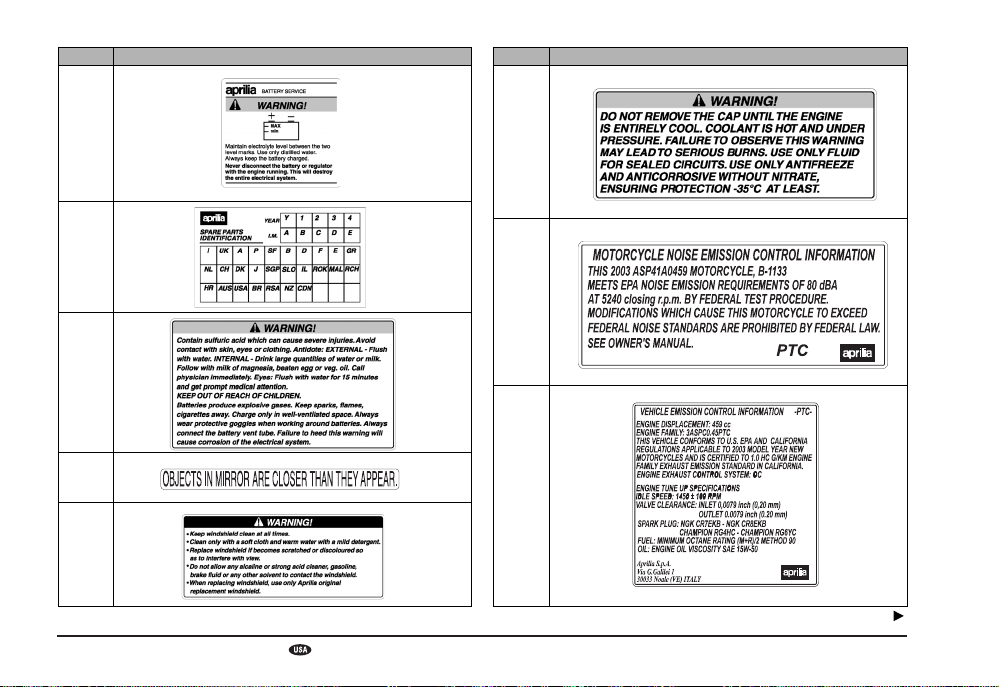
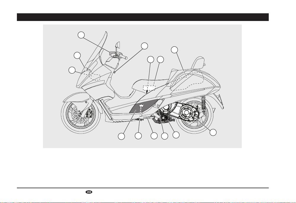
POSITION OF THE WARNING ADHESIVE LABELS
12
use and maintenance
8
A
B C
49 187
D E
1516
2a 6 14
Atlantic 500
19
3
10
8
17
5
11
13
1
Page 9

WARNING ADHESIVE LABELS CHART
Ref. Description
1
NOT PROVIDED FOR 49 STATES.
2
FOR STATE OF CALIFORNIA ONLY.
2a
3
Ref. Description
4
5
6
7
use and maintenance
Atlantic 500
Follow
9
Page 10
Ref. Description
Ref. Description
8
9
10
11
12
use and maintenance
10
13
14
15
Follow
Atlantic 500
Page 11

Ref. Description
Muffler stamping.
16
17
18
19
MAXIMUM WEIGHT LOAD
ALLOWED lbs 20 (kg 5)
use and maintenance
Atlantic 500
11
Page 12
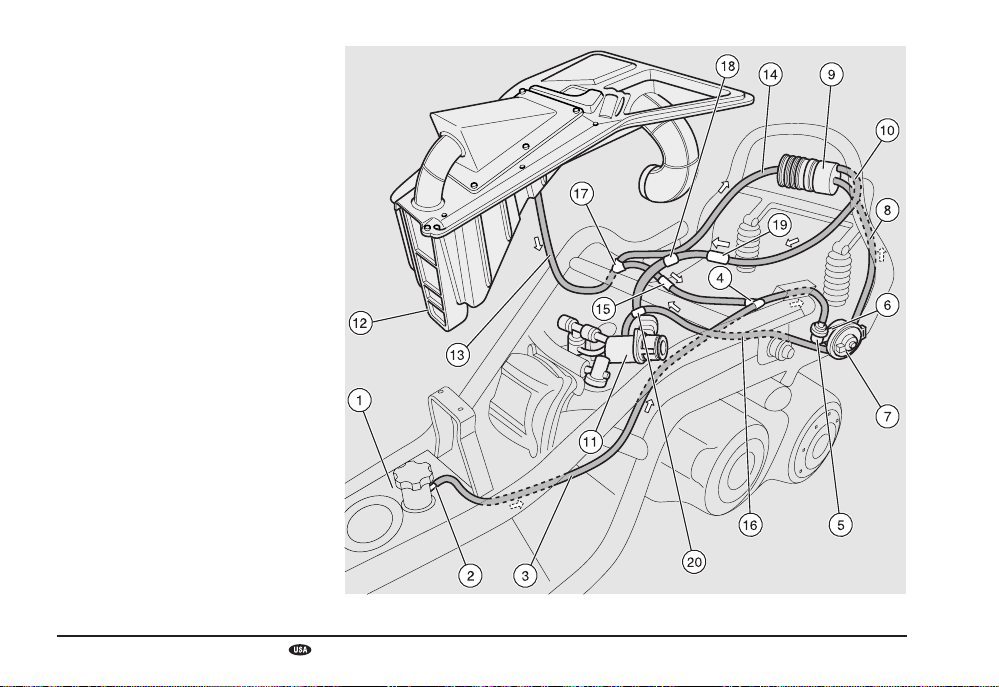
CALIFORNIA EVAPORATIVE
EMISSION SYSTEM
FOR STATE OF CALIFORNIA ONLY.
1) Fuel tank
2) Tank fumes relief
3) Tank fumes breather tube
4) Tee
5) Roll over valve
6) Roll over valve - purge valve connection
tube
7) Purge valve
8) Purge valve - carbon canister connection
tube
9) Carbon canister
10) Intake coupling hose
11) Throttle
12) Air box
13) Warm air inlet (from air box)
14) Carbon canister washing hose
15) One way valve
16) Purge valve - throttle connection tube
17) Tee
18) Narrow passage
19) Security valve
20) Tee
use and maintenance
12
Atlantic 500
Page 13

aprilia s.p.a. - EMISSION
CONTROL SYSTEM
WARRANTY STATEMENT
YOUR WARRANTY RIGHTS
AND OBLIGATIONS
The California Air Resources Board and
aprilia s.p.a. (hereinafter “aprilia”) are
pleased to explain the emission control system warranty on your 1999 and later motorcycle. In California new motor vehicles must
be designed, built and equipped to meet the
State’s stringent anti-smog standards.
aprilia must warrant the emission control
system on your motorcycle for the periods
of time listed below provided there has been
no abuse, neglect or improper maintenance
of your motorcycle.
Your emission control system may include
parts such as the carburetor or fuel injection
system, the ignition system, catalytic converter and engine computer. Also included
may be hoses, belts, connectors and other
emission-related assemblies.
Where a warrantable condition exists, aprilia
will repair your motorcycle at no cost to you,
including diagnosis, parts and labor.
MANUFACTURER’S EMISSIONS
SYSTEM WARRANTY COVERAGE
3
Class I motorcycles (50 – 169 cm
): for a
period of use of five (5) years or 12,000 kilometers (7,456 miles), whichever first occurs.
Class II motorcycles (170 – 279 cm
3
): for a
period of use of five (5) years or 11,185 miles
(18,000 kilometers), whichever first occurs.
Class III motorcycles (280 cm3 and larger):
for a period of use of five (5) years or 18,641
miles (30,000 kilometers), whichever first
occurs.
If an emission-related part on your motorcycle is defective, the part will be repaired or
replaced by aprilia. This is your emission
control system DEFECTS WARRANTY.
OWNER’S WARRANTY
RESPONSIBILITIES
– As the motorcycle owner, you are respon-
sible for the performance of the required
maintenance listed in your owner’s
manual. aprilia recommends that you
retain all receipts covering maintenance
on your motorcycle, but aprilia cannot
deny warranty solely for the lack of receipts or for your failure to ensure the
performance of all scheduled maintenance.
– You are responsible for presenting your
motorcycle to an aprilia dealer as soon
as a problem exists. The warranty repairs
should be completed in a reasonable
amount of time, not to exceed 30 days.
– As the motorcycle owner, you should be
aware that aprilia may deny your warranty coverage if your motorcycle or a part
has failed due to abuse, neglect, improper
maintenance or unapproved modifications.
If you have any questions regarding your
warranty rights and responsibilities, you
should contact aprilia USA, Inc., 10933
Crabapple Road, Suite 100, Roswell, GA
3007, or the California Air Resources
Board at P.O. Box 8001, 9528 Telstar Avenue, El Monte, CA 91734-8001.
use and maintenance
Atlantic 500
13
Page 14

aprilia s.p.a. - LIMITED
WARRANTY ON EMISSION
CONTROL SYSTEM
aprilia s.p.a., Via G. Galilei, 1, 30033 Noale
(VE) Italy (hereinafter “aprilia”) warrants
that each new 1999 and after aprilia mo-
torcycle, that includes as standard equipment
a headlight, taillight and stoplight, and is
street legal:
A. is designed, built and equipped so as to
conform at the time of initial retail purchase with all applicable regulations of the
United States Environmental Protection
Agency, and the California Air Resources
Board; and
B. is free from defects in material and work-
manship which cause such motorcycle to
fail to conform with applicable regulations
of the United States Environmental Protection Agency or the California Air Resources Board for a period of use, depending on the engine displacement, of
7,456 miles (12,000 kilometers), if the
motorcycle’s engine displacement is less
than 170 cubic centimeters; of 11,185
miles (18,000 kilometers), if the
motorcycle’s engine displacement is equal
to or greater than 170 cubic centimeters
but less than 280 cubic centimeters; or of
18,641 miles (30,000 kilometers), if the
motorcycle’s engine displacement is 280
cubic centimeters or greater; or 5 (five)
years from the date of initial retail delivery, whichever first occurs.
use and maintenance
14
Atlantic 500
I. COVERAGE. Warranty defects shall be
remedied during customary business
hours at any authorized aprilia motor-
cycle dealer located within the United
States of America in compliance with the
Clean Air Act and applicable regulations
of the United States Environmental Protection Agency and the California Air Resources Board. Any part or parts replaced
under this warranty shall become the property of aprilia.
In the State of California only, emission
related warranted parts are specifically
defined by the state’s Emission Warranty
Parts List. These warranted parts are:
carburetor and internal parts; intake manifold; fuel tank; fuel injection system; spark
advance mechanism; crankcase breather;
air cutoff valves; fuel tank cap for evaporative emission controlled vehicles; oil filler
cap; pressure control valve; fuel/vapor
separator; canister; igniters; breaker governors; ignition coils; ignition wires; ignition points; condensers, and spark plugs
if failure occurs prior to the first scheduled
replacement; and hoses, clamps, fittings
and tubing used directly in these parts.
Since emission related parts may vary
from model to model, certain models may
not contain all of these parts and certain
models may contain functionally equivalent parts.
In the State of California only, Emission
Control System emergency repairs, as
provided for in the California Administra-
tive Code, may be performed by other than
an authorized aprilia dealer. An emergency situation occurs when an authorized
aprilia dealer is not reasonably available,
a part is not available within 30 days, or a
repair is not complete within 30 days. Any
replacement part can be used in an emergency repair. aprilia will reimburse the
owner for the expenses, including diagnosis, not to exceed aprilia’s suggested
retail price for all warranted parts replaced
and labor charges based on aprilia’s recommended time allowance for the warranty repair and the geographically appropriate hourly labor rate. The owner may
be required to keep receipts and failed
parts in order to receive compensation.
II. LIMITATIONS. This Emission Control Sys-
tem warranty shall not cover any of the
following:
A. Repair or replacement required as a re-
sult of
(1) accident,
(2) misuse,
(3) repairs improperly performed or replacements improperly installed,
(4) use of replacement parts or accessories not conforming to aprilia specifications
which adversely affect performance and/
or
(5) use in competitive racing or related
events.
Page 15

B. Inspections, replacement of parts and
other services and adjustments required
for required maintenance.
C. Any motorcycle on which the odometer
mileage has been changed so that actual
mileage cannot be readily determined.
III. LIMITED LIABILITY
A. The liability of aprilia under this Emission
Control System Warranty is limited solely
to the remedying of defects in material or
workmanship by an authorized aprilia
motorcycle dealer at its place of business
during customary business hours. This
warranty does not cover inconvenience
or loss of use of the motorcycle or transportation of the motorcycle to or from the
aprilia dealer.
aprilia SHALL NOT BE LIABLE FOR
ANY OTHER EXPENSES, LOSS OR
DAMAGE, WHETHER DIRECT, INCIDENTAL, CONSEQUENTIAL OR EXEMPLARY ARISING IN CONNECTION
WITH THE SALE OR USE OF OR INABILITY TO USE THE aprilia MOTOR-
CYCLE FOR ANY PURPOSE. SOME
STATES DO NOT ALLOW THE EXCLUSION OR LIMITATION OF ANY INCIDENTAL OR CONSEQUENTIAL DAMAGES, SO THE ABOVE LIMITATIONS
MAY NOT APPLY TO YOU.
B. NO EXPRESS EMISSION CONTROL
SYSTEM WARRANTY IS GIVEN BY
aprilia EXCEPT AS SPECIFICALLY
SET FORTH HEREIN. ANY EMISSION
CONTROL SYSTEM WARRANTY IMPLIED BY LAW, INCLUDING ANY WARRANTY OF MERCHANTABILITY OR FITNESS FOR A PARTICULAR PURPOSE,
IS LIMITED TO THE EXPRESS EMISSION CONTROL SYSTEM WARRANTY
TERMS STATED IN THIS WARRANTY.
THE FOREGOING STATEMENTS OF
WARRANTY ARE EXCLUSIVE AND IN
LIEU OF ALL OTHER REMEDIES.
SOME STATES DO NOT ALLOW LIMITATIONS ON HOW LONG AN IMPLIED
WARRANTY LASTS SO THE ABOVE
LIMITATIONS MAY NOT APPLY TO YOU.
C. No dealer is authorized to modify this
aprilia Limited Emission Control System
Warranty.
IV. LEGAL RIGHTS. THIS WARRANTY
GIVES YOU SPECIFIC LEGAL RIGHTS,
AND YOU MAY ALSO HAVE OTHER
RIGHTS WHICH VARY FROM STATE TO
STATE.
V. THIS WARRANTY IS IN ADDITION TO
THE aprilia LIMITED MOTORCYCLE
WARRANTY.
VI. ADDITIONAL INFORMATION. Any re-
placement part that is equivalent in performance and durability may be used in
the performance of any maintenance or
repairs. However, aprilia is not liable for
these parts. The owner is responsible for
the performance of all required maintenance. Such maintenance may be performed at a service establishment or by
any individual. The warranty period begins on the date the motorcycle is delivered to an ultimate purchaser.
aprilia s.p.a.
Via G. Galilei, 1
30033 Noale (VE) Italy
aprilia USA, Inc.
110 Londonderry Ct., Suite 130
Woodstock, GA 30188
use and maintenance
Atlantic 500
15
Page 16

GENERAL iNSTRUCTIONS
The operations preceded by this symbol must be repeated also on the opposite side of the vehicle.
If not expressly indicated otherwise, for the
reassembly of the units repeat the disassembly operations in reverse order.
The terms “right” and “left” are referred to
the rider seated on the vehicle in the normal
riding position.
WARNING
The competition adjustment must be used
in organized racing or circular course
competitive event, under the auspices of
a recognized sanctioning body or by permit issued by the local governmental authority having jurisdiction.
It is strictly forbidden to use the competition adjustment while riding the vehicle
on public streets, roads, or highways.
NOTE Soon after purchasing the vehicle,
write down the identification data provided
in the SPARE PARTS IDENTIFICATION
LABEL in the table below. This label is positioned on the left part of the frame; to be able
to read it, remove the left inspection cover,
see page 69 (REMOVING THE RIGHT AND
LEFT INSPECTION COVERS).
These data indicate:
– YEAR = year of manufacture (Y, 1, 2, …);
– I.M. = modification code (A, B, C, …);
– COUNTRY CODE = country of homolo-
gation (I, UK, A, …).
and are to be supplied to the Local aprilia
Dealer as reference data for the purchase of
spare parts or specific accessories of the
model you have acquired.
In this manual the various versions are indicated by the following symbols:
Automatic Switch-on Device
optional
VERSION:
Italy
United Kingdom
Austria
Portugal
Finland
Belgium
Germany
France
Spain
Greece
Holland
Switzerland
Denmark
Japan
Singapore
Poland
Israel
South Korea
Malaysia
Chile
Bermuda
United States
of America
Australia
Brazil
South Africa
New Zealand
Canada
Croatia
Slovenia
Turkey
use and maintenance
16
Atlantic 500
Page 17

NOTE
ASK FOR GENUINE SPARE PARTS ONLY
use and maintenance
Atlantic 500
17
Page 18

MAIN INDEX
SAFE RIDING ................................................... 19
BASIC SAFETY RULES ................................ 20
CLOTHING .................................................... 25
ACCESSORIES ............................................. 26
LOAD ............................................................. 26
POSITIONS OF MAIN PARTS ......................... 28
POSITIONS OF CONTROLS/INSTRUMENTS 30
INSTRUMENTS AND INDICATORS ................ 30
TABLE OF INSTRUMENTS AND
INDICATORS................................................. 31
MAIN INDIVIDUAL CONTROLS ...................... 33
CONTROLS ON THE
LEFT SIDE OF THE HANDLEBAR ............... 33
CONTROLS ON THE
RIGHT SIDE OF THE HANDLEBAR ............. 34
IGNITION SWITCH ....................................... 35
STEERING LOCK ......................................... 35
DIGITAL CLOCK/CALENDAR ....................... 36
MULTIFUNCTION LCD ................................. 37
DIGITAL ODOMETER ................................... 38
TOOL KIT ...................................................... 39
LOCKING/RELEASING THE SADDLE ......... 39
STORAGE COMPARTMENT ........................ 40
GLOVE COMPARTMENT ............................. 40
BAG CARRYING CLIP .................................. 40
HELMET CLIP ............................................... 40
MAIN COMPONENTS ...................................... 41
FUEL ............................................................. 41
LUBRICANTS ................................................ 42
TRANSMISSION OIL .................................... 42
ENGINE OIL .................................................. 42
BRAKE FLUID - recommendations ............... 43
DISC BRAKES .............................................. 43
COOLANT ..................................................... 45
CHECKING AND TOPPING UP .................... 46
TIRES ............................................................ 47
TIRE PRESSURE .......................................... 48
AUTOMATIC SWITCH-ON
DEVICE VERSION ........................................ 48
use and maintenance
18
Atlantic 500
MUFFLER/EXHAUST SILENCER ................. 48
RIDING RULES ................................................ 49
TABLE OF PRELIMINARY CHECKS ............ 49
STARTING..................................................... 50
TAKE-OFF AND RIDING ............................... 52
BREAKING-IN ............................................... 54
STOPPING .................................................... 54
POSITIONING THE VEHICLE ON THE
SIDE STAND ................................................. 55
SUGGESTIONS AGAINST THEFT ............... 56
MAINTENANCE ............................................... 56
SCHEDULED MAINTENANCE
CHART .......................................................... 57
IDENTIFYING INFORMATION ...................... 59
CHECKING ENGINE OIL LEVEL AND
TOPPING UP ................................................ 60
ENGINE OIL CHANGE AND OIL FILTER .... 61
CHECKING AND TOPPING UP THE
TRANSMISSION OIL LEVEL ........................ 61
CHANGING THE TRANSMISSION OIL ........ 62
AIR FILTER ................................................... 63
CHECKING THE BRAKE PAD WEAR .......... 64
CHECKING THE SIDE STAND ..................... 66
CHECKING THE SWITCHES ....................... 66
INSPECTING THE FRONT E REAR
SUSPENSION ............................................... 66
ADJUSTING THE REAR
SUSPENSION ............................................... 67
STEERING CONTROL .................................. 67
CHECKING THE ENGINE FULCRUM .......... 68
REMOVING THE RIGHT AND LEFT
INSPECTION COVERS ................................ 69
REMOVING THE FRONT FAIRING .............. 69
REMOVING THE
REARVIEW MIRRORS ................................. 70
REMOVING THE FRONT HOOD .................. 70
ADJUSTING THE
THROTTLE CONTROL ................................. 71
SPARK PLUG ................................................ 72
BATTERY ...................................................... 73
EXTENDED BATTERY
STORAGE OF THE BATTERY ...................... 73
REMOVAL THE BATTERY COVER .............. 74
CHECKING AND CLEANING TERMINALS .. 74
REMOVING THE BATTERY.......................... 74
CHECKING THE LEVEL OF BATTERY
ELECTROLYTE ............................................. 75
BATTERY RECHARGING ............................. 75
BATTERY INSTALLATION ............................ 75
CHANGING FUSES ...................................... 76
SECONDARY FUSE LAYOUT
(FRONT HOOD) ............................................ 76
MAIN FUSE LAYOUT
(BATTERY COMPARTMENT) ....................... 77
VERTICAL ADJUSTMENT HEADLIGHT
BEAM ............................................................ 77
HORIZONTAL ADJUSTMENT HEADLIGHT
BEAM ............................................................ 78
BULBS ........................................................... 78
CHANGING THE FRONT DIRECTION
INDICATOR LAMPS ...................................... 78
CHANGING
HEADLIGHT BULBS ..................................... 79
LOW BEAM BULBS ...................................... 79
HIGH BEAM BULBS ...................................... 80
PARKING LIGHT BULBS .............................. 80
CHANGING TAILLIGHT
BULBS ........................................................... 80
CHANGING THE LICENSE
PLATE LAMP BULB ...................................... 81
CHANGING THE
HELMET COMPARTMENT LIGHT BULB ..... 82
TRANSPORT ................................................... 82
DRAINING THE FUEL TANK ........................ 83
CLEANING ....................................................... 83
PERIODS OF EXTENDED STORAGE ......... 84
TECHNICAL SPECIFICATIONS ...................... 86
LUBRICANT CHART ..................................... 90
WIRING DIAGRAM ....................................... 94
WIRING DIAGRAM LEGEND ........................ 95
Page 19

safe riding
Page 20

BASIC SAFETY RULES
The instructions given below cover normal
operation of your vehicle and must be carefully observed. By following these rules you
will enhance your own safety and the safety
of those around you. You will also maximize
the life and utility of your vehicle.
Two wheeled vehicles obviously do not provide some of the protection provided by automobiles, therefore it is essential that you
wear appropriate protective clothing. Especially, never operate your vehicle without
wearing your helmet, gloves, eye protection,
a heavy jacket, sturdy footwear, and sturdy
full length pants.
However, do not assume that even the best
clothing and helmet will protect you in the
event of an upset or a crash with another
vehicle. At best, this gear provides some protection from scrapes and scratches, but very
little, if any, impact protection.
Be sure that you meet all the requirements
prescribed by local law, including driver’s license, minimum age, training, insurance,
taxes, vehicle registration, license plate, etc.
When you first receive your vehicle, practice
by riding in areas where there is little traffic.
Do not attempt to ride in heavy traffic until you
are thoroughly experienced and riding your
vehicle has become second nature to you.
Although this vehicle is legal for operation
use and maintenance
20
Atlantic 500
on freeways and expressways, it is advisable to not ride on these high speed highways until you are thoroughly familiar with
your vehicle, and have attained a high degree of skill in its operation.
A new vehicle must be carefully broken in,
see p.54 (BREAKING-IN).
Before starting the engine, make sure that
the brakes, clutch, transmission and throttle
controls function properly and that the fuel
and oil supply is adequate.
The exhaust system, brakes, and some other
parts of the vehicle become very hot during
operation. Do not touch any of these parts.
Some medicines or drugs, illegal or prescription, and alcohol significantly increase the
risk of accidents. Do not ride while you are
under the influence of alcohol or drugs, be
they illicit or prescription. Make sure you are
in good physical condition and not ill before
riding your vehicle. Do not ride your vehicle
when you are particularly tired or fatigued.
Alcohol, drugs and fatigue are leading
causes of vehicle accidents.
Many accidents are caused by the rider’s
inexperience and lack of training. Do not ride
your vehicle until you have received training
from a recognized training organization such
as the Motorcycle Safety Foundation. Remember that riding a two wheeled vehicle,
though easy and fun, is quite different from
driving a car. Do not assume that you can
operate your vehicle safely just because you
are a competent automobile driver.
Never lend your vehicle to others unless you
are sure that they are competent and properly licensed vehicle operators.
Page 21

Observe all rules of the road. Particularly pay
attention to all warning, regulatory and informational signs.
Avoid showing off (i.e., popping wheelies).
Especially observe speed limits, remember
that road conditions change with the weather
and wet and icy pavements are particularly
dangerous for vehicles, especially if you are
riding too fast. Remember that automobile
drivers have a hard time seeing two wheeled
vehicles, so always give the automobile the
right of way, even if it is legally yours.
Before changing lanes, look over your shoulder to make sure that the way is clear. Do
not rely exclusively on the rear-view mirror:
you may miscalculate the distance and speed
of a vehicle, or you may even not see it at
all.
Avoid obstacles that could damage the vehicle or make you lose control.
Do not tailgate, do not attempt to increase
your gas mileage by following in the slip
stream of cars or trucks in front of you.
In case of accident motorcycles, scooters
and mopeds do not provide the same degree of protection ensured by automobiles.
The legs, in particular, are exposed the risk
of being injured. However, the additional installation of leg guards may actually increase
the risk of injuries and their seriousness in
case of accident.
Do not install leg guards available on the
market of spare parts and accessories. Noncompliance with these instructions may result in serious injuries or even death.
Always ride with both hands on the handlebars and feet on the footrests.
Never shift gear without using the clutch, if
the vehicle is so equipped. Do not operate
the shift lever or the other controls suddenly
or abruptly. Such misuse can damage the
internal components of the vehicle and consequently cause seizure, loss of control, accidents and serious injuries or even death.
Remain in the seat when you are riding. Do
not stand up or attempt to stretch while you
are riding your vehicle. If you need to rest,
pull over to the side of the road when it can
be safely done.
use and maintenance
Atlantic 500
21
Page 22

OIL
COOLER
It is very important to your safety that you
give full attention to the riding task. Watch
what you are doing, do not allow yourself to
be distracted by other cars, people or things
on the roadside, etc. Never smoke, eat, drink,
read, etc. while riding your vehicle. If you
must consult a map, pull over when it can be
done safely.
Use only the vehicle’s specific fuels and lubricants indicated in the “LUBRICANT
CHART”; check the oil, fuel and coolant levels regularly.
If the throttle sticks open, it may cause a
collision with another vehicle, or an upset.
If the throttle sticks, kill the engine with the
engine stop switch located on the right
handlebar.
Do not attempt to restart the engine until the
throttle has been repaired and works perfectly.
Failure to obey this warning can lead to a runaway with seriously injuries or even death.
use and maintenance
22
Atlantic 500
WARNING
In the event of a throttle sticking emergency, always kill the engine using the
engine stop switch located near the throttle grip on the right handlebar. Never use
your vehicle if the throttle does not automatically fully return to the idle position
when the throttle grip is released. Contact your Local aprilia Dealer for repairs.
Failure to heed this warning can lead to a
serious accident and subsequent injury
or even death.
If you and your vehicle are involved in an
accident, insure that there has been no damage to the control levers, tubes, wires, braking system and other vital parts. If your vehicle is involved in an accident, take it immediately to your Local aprilia Dealer who has
the equipment and knowledge to check for
accidental damage which may compromise
your safety.
Your aprilia dealer is ready and able to help
you with any safety problems that you might
have, but of course it is necessary for you to
report any malfunctions to your mechanic in
order for him to help you.
Do not use your vehicle if it is damaged. A
damaged vehicle may become unstable or
present other problems which can increase
the risk of accident, and therefore of serious
injury or even death.
Page 23

A12
345
ONLY ORIGINALS
Do not attempt to modify the position, angle
or color of your license plate. Do not cover it
with even a clear plastic covering. Do not
modify any of the safety equipment of your
vehicle, especially such safety related items
as directional indicators, rear view mirrors,
lights or horns.
Any modification to your vehicle will invalidate the warranty.
Do not modify your engine in an attempt to
increase the horsepower. This can result in
irreparable damage to the engine, as well
as degradation of the performance and handling of the vehicle which could lead to an
upset, and serious injury or even death.
Have your vehicle repaired only with original
parts, and use only original aprilia or
aprilia approved accessories. The use of
aftermarket accessories and parts can seriously compromise the safety of your vehicle
as well as its performance and serviceability. Any modification which affects performance or safety voids your warranty completely.
Tampering with the emissions or noise control systems on your vehicle is against the
law, and can be punished by large fines.
In some jurisdictions, it can even lead to the
confiscation of your vehicle.
This vehicle was not designed to be equipped
with a sidecar or to be used to tow trailers or
other vehicles.
aprilia does not manufacture sidecars or
trailers and therefore cannot predict the effects of such accessories on the
manoeuvrability or stability of the vehicle: it
can only warn that such effects may be negative and that any damage to the vehicle components caused by the use of such accessories will not be covered by the warranty.
use and maintenance
Atlantic 500
23
Page 24

Never race other vehicles with your vehicle.
Brake with both the front and rear brakes.
The use of one brake only for sudden braking may cause the vehicle to skid or make
the rider lose control of the vehicle itself.
When riding down a steep hill, use the engine as a brake by selecting the same gear,
or a lower gear, than you would use to climb
the hill. Use front and rear brakes sparingly.
Always ride at the appropriate speed and
avoid unnecessary hard acceleration. This
not only is safer, but also reduces fuel consumption and increases the life of the vehicle.
If you must ride your vehicle in rainy weather,
or on loose surfaces, remember that traction
is greatly reduced. Under these conditions,
all handling of the vehicle must be done
gradually and smoothly. Sudden acceleration, braking or turning may make you lose
control of your vehicle. When traction is reduced, accelerate and slow using your vehicle’s engine braking insofar as possible.
Avoid rapid, harsh application of the brakes.
Gradually open and close the throttle, to
avoid spinning or skidding the rear wheel.
On rough road surfaces, slow down and ride
with particular care.
Try to avoid wide open throttle accelerations,
unless they are necessary for such things
as passing.
Don’t allow your engine to “lug,” that is, run
at too low an rpm. Shift down to a lower gear.
Also, don’t over-rev the engine. Observe the
redline on the tachometer.
Remember that excessively aggressive cornering can cause your vehicle’s tires to lose
sideways traction, which can result in an
upset and serious injury or even death.
use and maintenance
24
Atlantic 500
Page 25

Always observe posted and statutory speed
limits, but do not assume that you can ride
as fast as the speed limit under all road conditions. Slowing down a little can greatly increase your safety under all road conditions.
Do not ride your vehicle off road.
Do not tamper with the muffler system or the
emissions control system of your vehicle.
This is not only bad for the environment, it
can subject you to serious penalties.
CLOTHING
Before riding your vehicle, ensure that your
riding gear is in good condition. To be effective, your helmet must fit properly, and the
visor or other eye protection must be clean.
Both research and experience have shown
that drivers of other vehicles often do not see
vehicles or riders. In order to make yourself
more conspicuous to these drivers, wear
bright reflective clothing, such as a reflective vest, or clothing with reflective sections
sewn into the jacket, pants and gloves. Be
particular aware of approaching automobiles
and trucks that might be trying to turn left in
front of you. Many vehicle accidents are
caused by an opposing automobile driver
making a left turn without warning in front of
the vehicle.
Inevitably, the driver will look right at you, and
yet swear that they did not see you before
they turned directly into your path. Ride alert!
Wear protective clothing, preferably in light
and/or reflecting colours. In this way you will
make yourself more visible to the other drivers, thus notably reducing the risk of being
knocked down, and you will be more protected in case of fall.
Always wear your crash helmet. Many accidents are fatal because of injuries to the
head.
This clothing should be very tight-fitting and
fastened at the wrists and ankles. Strings,
belts and ties should not be hanging loose;
prevent these and other objects from interfering with driving by getting entangled with
moving parts or driving mechanisms.
use and maintenance
Atlantic 500
25
Page 26

Do not carry sharp objects in your pockets
that could be dangerous in case of an upset,
for example, pens or mechanical pencils, etc.
Also, make sure that your passengers follow this recommendation.
ACCESSORIES
The owner of the vehicle is responsible for
the choice, installation and use of any accessory.
The installation of inappropriate accessories
or the overloading of the vehicle may result
in the instability of the vehicle itself and cause
accidents with consequent risk of serious
injuries or even death. Windshields could be
particularly dangerous, as they can break
and injure or cut the rider in case of accident. In case of doubts with regard to any
accessory you would like to install or any load
you would like to carry, previously consult
your Local aprilia Dealer.
use and maintenance
26
Atlantic 500
Avoid installing accessories that cover horns
or lights or that could impair their functions,
limit the suspension stroke and the steering
angle, hamper the operation of the controls
and reduce the distance from the ground and
the angle of inclination in turns.
Avoid using accessories that hamper access
to the controls, since this can prolong reaction times during an emergency.
Fairings and windshields installed on the
vehicle may produce aerodynamic forces that
will affect the stability of the vehicle during
use, especially at high speeds.
Make sure that anything you carry on your
vehicle is securely attached, and cannot
come lose and jam the wheels, forks, etc.
Do not install any electrical accessories, and
do not modify the electrical system of your
vehicle. Anything that could cause an electrical overload or other fault could cause the
vehicle to suddenly stop, the lights to dim or
quit, or the horn and other safety accessories not to work. Use only genuine aprilia
accessories.
LOAD
Do not overload your vehicle. Attach luggage
or packages as close as possible to the center of your vehicle and distribute the load from
side to side as evenly as possible, to keep
imbalance to a minimum. Remember that
loads tend to loosen with riding, so frequently
check the security of your load.
Page 27

KG!
Do not hang anything from your vehicle handlebars, fenders, or forks, because this will
upset the handling of your vehicle, and could
prevent you from avoiding an accident. Failure to heed this warning can lead to an upset
with subsequent serious injury or even death.
Do not ride with your crash helmet hung from
the strap because it could easily foul the
wheels, fenders, or forks, causing an upset
and subsequent serious injury or even death.
Carry a passenger only if your vehicle is
equipped with passenger footrests, handgrips
for the passenger to hold on to, and a passenger saddle.
When carrying a passenger, remember that
your vehicle’s handling is degraded, that the
brakes are less efficient, and the center of
gravity is higher and further to the rear.
This makes it more likely that the front wheel
will come up off the ground, especially on
acceleration. Therefore, you should avoid
hard acceleration and hard braking. Many
accidents are caused by inexperienced riders carrying passengers. Remember that allowance must be made for the extra weight
of the passenger for all driving maneuvers.
Avoid abrupt and excessive acceleration.
Always slow down in time and calculate
longer stopping and manoeuvring distances.
Non-compliance with these instructions may
lead to the overturning of the vehicle or to
other accidents with consequent serious injuries or even death.
Never carry loosely packaged items, make
sure that everything that you carry on your
vehicle is carefully secured.
Do not carry packages which protrude from
the luggage rack or which cover any of the
signal lights, the headlight, or the horn.
Never carry animals or children on the glove
compartment or on the luggage rack.
Never exceed the labeled maximum load for
each saddlebag.
Overloading your vehicle seriously reduces
its stability and maneuverability and can lead
to an upset with subsequent serious injury
or death.
use and maintenance
Atlantic 500
27
Page 28
POSITIONS OF MAIN PARTS
3
use and maintenance
28
2
1
LEGEND
1) Expansion tank
2) Coolant expansion tank plug
3) Rear brake fluid reservoir
4) Bag carrying clip
5) Helmet clip
Atlantic 500
4
6
5
11
12
13
6) Air filter
7) Helmet compartment
8) Variator air filter cover
9) Center stand
10) Left passenger footrest
10
7
9
8
11) Side stand
12) Spark plug
13) Left inspection cover
Page 29

1
2
3
4
5
6
7
8
10
9
LEGEND
1) Battery
2) Main fuse box
3) Passenger grab handle
4) Fuel tank
5) Fuel tank cap
13
6) Fuel reservoir cap door
7) Front brake fluid reservoir
8) Ignition switch /steering lock/
saddle opening
9) Horn
12
11
10) Secondary fuse box
11) Right inspection cover
12) Right passenger footrest
13) Engine oil level / filler cap
use and maintenance
Atlantic 500
29
Page 30

INSTRUMENTSARRANGEMENT OF THE INSTRUMENT/CONTROLS
4
3
2
LEGEND
1) Electrical controls on the left side of the handlebar
2) Combined brake lever (front and rear)
3) Left rearview mirror
4) Instruments and indicators
5) Right rearview mirror
6) Front brake lever
7) Throttle handgrip
8) Electrical controls on the right side of the handlebar
9) Ignition switch / steering lock (
10) Speaker protection grids(
LEGEND
1) Red engine oil pressure LED (
2) Green left direction indicator LED ( )
3) Digital odometer
4) Speedometer
use and maintenance
30
1
).
Atlantic 500
8
9
- - )
)
7
10
21
17
2
6
1
15
16
4
8
13
5
14
11
6
ABS
7
10
5
5) Green right direction indicator LED ( )
6) Blue high beam LED ( )
7) Amber yellow fuel reserve LED ( )
8) Fuel level indicator (
9) Button to select functions and set the digital clock
10) Digital clock
11) Coolant temperature indicator (
12) Red high coolant temperature LED ( )
13) Green parking lights and high beam LED ( )
14) Parking brake LED (
15) Amber side stand down LED ( )
16) LED “EFI”
17) Tachometer
18) LCD
19) Display function selection for 3 and resetting 18 and 3
20) Red ABS LED (
21) Red Immobilizer LED ( )
9
) (only for versions provided with ABS)
18
20
)
)
3
)
12
19
Page 31

TABLE OF INSTRUMENTS AND INDICATORS
CAUTION
Description
Right direction indicator LED ( )
Left direction indicator LED ( )
Engine oil pressure LED (
Total digital odometer
Speedometer
High beam LED (
Fuel reserve LED (
Fuel level indicator (
Digital clock
Immobilizer LED
Parking brake LED
With the key set to on “ ”, for the first 3 seconds all of the prepared warning lights light, including all
dashboard lighting and all segments of the 3 displays, to perform an initial instrumentation check.
Function
Flashes when the right turn signal is on.
Flashes when the left turn signal is on.
Lights whenever the ignition switch is set to “
)
)
)
)
)
(
the efficiency of the LED. The LED must shut off when the engine is started.
CAUTION
In this case stop the engine immediately and contact your nearest aprilia dealer.
Indicates the total mileage traveled, and trip mileage (TRIP 1, TRIP 2) see page 38.
Indicates the driving speed.
Lights when the high beam bulb of the headlight is activated, or when the high beams are
flashed (PASSING ).
Lights when the fuel tank contains approximately 4 liters of fuel.
Indicates the approximate fuel level in the tank. When the indicator reaches the red area,
the tank contains approximately 4 liters of fuel.
When this occurs, refuel as soon as possible, see page 41 (FUEL).
Either the time or date may be shown on the display, see page 36 (DIGITAL CLOCK).
Only for certain vehicles. With the motorcycle shut off it flashes as a deterrent against theft.
Confirms that the antitheft system is activated.
Only for certain vehicles. Indicates that the hand brake is activated.
CAUTION
” and the engine is not started, thereby testing
If the LED lights while the engine is running normally, it means
that the engine oil pressure in the circuit is too low.
Disengage before moving.
use and maintenance
Atlantic 500
31
Page 32

Description
ABS LED (Anti braking system) (
Coolant temperature indicator (
High coolant temperature LED (
Headlights LED ( )
Side stand down LED (
Electronic fuel injection (EFI) control
LED
Tachometer
Multifunction LCD
)
)
)
Function
Only for vehicles where installed. Checks the antilock system. Lights in case of error.
)
CAUTION
case stop the engine immediately and contact an aprilia dealer.
Indicates the approximate coolant temperature in the engine. When the indicator starts to
move away from the “Min” level, the temperature is high enough to ride the vehicle. Normal
running temperature lies in the center area of the scale. If the indicator reaches the red zone or
the LED lights, stop the engine and check the coolant level, see page 45 (COOLANT).
CAUTION
Lights when the coolant temperature indicator reaches the red zone. Stop the engine immediately and check the coolant level, see page 45 (COOLANT).
CAUTION
Lights when the headlight bulb is activated.
Lights when the side stand is down.
CAUTION
Lights for approximately three seconds whenever the ignition switch is set to “
gine not is started, thus performing a functional test of the injection system. The LED must shut
off when the engine is started.
CAUTION
system. In this case stop the engine immediately and contact an aprilia dealer.
Indicates the engine rpm.
The display may show the external temperature, maximum speed, average speed, battery
voltage, mean fuel consumption since the last “RESET”, timer and mileage remaining until
the next scheduled maintenance of the vehicle, see page 37 (MULTIFUNCTION LCD).
If the LED lights while the engine is running normally, it means
that a problem has occurred in the antilock system. In this
If the temperature exceeds the maximum allowed limit (red
“Max” zone of the scale), it may seriously damage the engine.
If the temperature exceeds the maximum allowed limit for an
extended period of time, it may seriously damage the engine.
With the side stand extended, the LED is on and the vehicle
may not be started.
” and the en-
If the LED lights while the engine is running normally, it means
that a problem has occurred in the electronic fuel injection
use and maintenance
32
Atlantic 500
Page 33

MAIN INDIVIDUAL CONTROLS
CONTROLS ON THE LEFT SIDE OF THE
HANDLEBAR
NOTE The electrical components only work with the ignition switch
”.
set to “
1) HORN BUTTON (
When pressed, it activates the horn.
2) DIRECTION INDICATOR SWITCH (
Move the switch to the left to indicate a left turn; move the switch
to the right to indicate a right turn. Set the switch to the center to
turn off the direction indicator. With the vehicle moving, the automatic restore system trips to shut off the direction indicator after
40 seconds or 500 m.
3) LIGHT DIMMER (
(PASSING
When the lever is in the position indicated by the “
)
)
- ) / HIGH BEAM FLASHER BUTTON
)
”, the parking
lights, dashboard light and low beam are on.
When the lever is moved to the “
”, the high beam is illumi-
nated,the dashboard and parking lights remain on.
Pressing the light dimmer to (PASSING
) will flash the high beam.
NOTE When the light dimmer is released, the high beam stops
flashing.
4) MODE BUTTON (MODE)
Press repeatedly to select the various data displayed on the multifunction LCD.
2
1
5) HAZARD BUTTON (
ON Press to engage the four blinkers; at this point it is possible
to turn the ignition switch to
)
and remove the key.
3
G
IN
S
S
PA
MODE
4
OFF
Insert the key in the ignition switch, and turn to “
”, press the
HAZARD button again to turn off the system.
use and maintenance
Atlantic 500
5
33
Page 34

CONTROLS ON THE RIGHT SIDE OF THE
HANDLEBAR
1
NOTE The electrical components only work with the ignition switch
set to “
”.
1) ENGINE STOP SWITCH (
- )
WARNING
Do not trip the engine stop switch “
cycle is moving.
2
It acts as a safety or emergency switch. The engine may be
started when the switch is pressed to “
will stop the engine.
- ” while the motor-
”; pressing it to “ ”
CAUTION
Keeping the ignition key set to “
may drain the battery.
With the vehicle stopped, after shutting off the engine, turn the
ignition switch to “
”.
” with the engine stopped
use and maintenance
34
Atlantic 500
2) START BUTTON (
When the button “
the engine. For the starting procedure, read page 50 (START-
ING).
SHUTTING OFF
Insert the key in the ignition switch, and turn it to “
automatically shuts off.
)
“ is pressed, the starter motor turns over
”; the device
Page 35

1
2
Position
Function
Removing
Key
P
ZADI
PUSH
IGNITION SWITCH
The ignition switch (1) is on the right side,
near the steering column.
NOTE The key (2) operates the ignition
switch/steering lock, the saddle lock and
glove compartment door.
Two keys (including one spare) are delivered with the vehicle.
NOTE Store the spare key separately from
the vehicle.
I
D
A
Z
PU
SH
STEERING LOCK
WARNING
Never turn the key to “ ” while running,
to avoid losing control of the vehicle.
OPERATION
To lock the steering:
♦ Turn the handlebars all the way to the left.
♦ Turn the key (2) to “ ”.
♦ Remove the key.
To open the compartments:
♦ Press the key (2), then turn clockwise to
open the glove compartment.
♦ Press the key (2), then turn it counter-
clockwise to lock/release the saddle and
access the saddle compartment.
The steering
is locked.
It is not
lock
possible to
start the
engine and
Steering
operate the
lights.
The engine
and the
lights
cannot be
switched
on.
The engine
and the
lights may
be switched
on.
use and maintenance
The key may
be removed.
The key may
be removed.
The key
may not be
removed.
Atlantic 500
35
Page 36

1
ABS
2
3
DIGITAL CLOCK/CALENDAR
NOTE The LCDs function only with the ig-
nition switch set to “
Description of the functions available on
the LCD (1):
♦ Normal display: hours and minutes.
♦ Date display: press the key (3) (SET); the
number of the month and day will appear
for less than five seconds.
”.
Setting the clock:
NOTE The clock must be set with the en-
gine off, the motorcycle stopped and direction indicators switched off.
♦ Hold down the key (2) (W) for more than
three seconds to activate the clock setting mode (ONLY WHEN THE TIME IS
DISPLAYED).
♦ Press or hold down the key (3) (SET) to
set the desired time.
♦ Press the key (2) (W) to confirm the time
setting and the clock will automatically
switch to setting the minutes.
♦ Press or hold down the key (3) (SET) to
set the desired minutes.
♦ Press the key (2) (W) to confirm the min-
utes setting.
♦ The clock is thus set and returns to nor-
mal operation.
Adjusting the calendar:
♦ Hold down the key (2) (W) for more than
three seconds to activate the calendar
setting mode (ONLY WHEN THE DATE
IS DISPLAYED).
♦ Press or hold down the key (3) (SET) to
set the desired day.
♦ Press the key (2) (W) to confirm the day
setting, and the calendar automatically
switches to the month setting.
♦ Press or hold down the key (3) (SET) to
set the desired month.
♦ Press the key (2) (W) to confirm the month
setting.
♦ The calendar is thus set and returns to
normal operation.
CAUTION
For safety reasons, the clock and calendar may be set only with the motorcycle
stopped and the engine off, and with the
direction indicators switched off.
use and maintenance
36
Atlantic 500
Page 37

2
I
D
A
Z
P
U
S
H
1
MULTIFUNCTION LCD
When the ignition key (1) is turned to position “
”, on the multifunction LCD all seg-
ments are activated (this performs a functional test of the components) and the last
function set after the vehicle was stopped will
be displayed.
CAUTION
After the first 625 mi (1,000 Km) and every 3,750 mi (6,000 Km) thereafter, the
message SERVICE appears on the display.
In this case contact an aprilia dealer to
carry out the operations described in the
scheduled maintenance chart, see page
57 (SCHEDULED MAINTENANCE CHART).
6
7
8
9 10
5
Km/h
BATT
mph
SERVICE
LAP
AVG V
Km/l Vmax
°C
°F
CEV
11
4
3
The various functions are selected and then
shown on the display by pressing the button
(MODE) (2) located on the controls on the
left side of the handlebar.
The following segments make up the multifunction LCD:
Stopwatch function indicator (3), scheduled
maintenance due icon (4), average speed
icon in miles per hour (mph) (5), average
speed (6), battery voltage icon (7), average
speed expressed in kilometers per hour icon
(Km/h) (8). (The same icon is used for the
“consumption levels” function expressed with
the symbol Km/l), consumption levels
espresso in G/ml (used only for the
versions) (9), maximum speed icon (10), external temperature icon expressed in degrees Celsius (°C) (11), external temperature icon expressed in degrees Fahrenheit
(°F) (12), six-digit display of the values for
13 12
the functions set and identified by the corresponding icons (13).
Pressing the MODE key, the following functions are obtained in sequence:
Outside temperature in ° C
↓
MODE
↓
Maximum speed + km/h or mph
MODE
↓
Average speed (km/h or mph)
MODE
↓
Battery charge (Bbatt)
MODE
↓
Fuel consumption (km/L or ML/G)
MODE
↓
Chronometer (LAP)
MODE
Programmed maintenance intervals
↓
(SERVICE)
MODE
use and maintenance
Atlantic 500
37
Page 38

Pressing the TRIP key produces the following functions in sequence:
3
4
ODO TRIP 1 TRIP 2
7
1
2
I
D
A
Z
P
U
S
H
6
5
↓
Odometer (ODO)
TRIP
↓
TRIP 1
TRIP
↓
TRIP 2
TRIP
RESETTING THE AVERAGE SPEED,
MAXIMUM SPEED, FUEL CONSUMPTION
LEVELS AND STOPWATCH VALUES
NOTE The corresponding information may
be reset only if the right digital display shows
the odometer.
♦ Hold down the key (1) (TRIP) for more
than three seconds.
NOTE The function displayed will be reset.
START/STOP AND RESETTING THE
STOPWATCH
NOTE the corresponding information may
be reset only if the right digital display shows
the odometer.
START/STOP:
hold down the key “MODE” (2) for more than
three seconds.
RESET:
♦ Hold the key (1) (TRIP) down for longer
than three seconds only when the stopwatch is stopped.
use and maintenance
38
Atlantic 500
DIGITAL ODOMETER
NOTE The LCDs operate only with the ig-
nition switch set to “
When the ignition key (3) is turned to position “
”, all segments are activated on the
LCD to perform a functional test of components, and the odometer will always be displayed.
The following segments make up the LCD:
Odometer display icon (4), first trip display
icon (5), second trip display icon (6), fivedigit display of the values corresponding to
the selected functions (7).
”.
TRIP VALUE RESET
TRIP 1/TRIP 2
♦ Press the key (1) (TRIP) for the selected
TRIP mode for longer than three seconds.
NOTE The function displayed will be reset.
Page 39

1
aprilia
4
I
D
A
Z
PUSH
2
3
687
5
TOOL KIT
The tool kit (1) is fastened inside the bottom
of the helmet/storage compartment, under
the saddle.
To access it:
Lift the saddle, see page 39 (LOCKING/RELEASING THE SADDLE).
The tools supplied include:
– 0.15 in (4 mm) male hex wrench;
– dual-tipped Philips/blade screwdriver;
– screwdriver handle;
– 0.12 in (3 mm) male hex wrench;
– 0.62x2.75 in (16x70 mm) pipe wrench with
hex;
– 0.51 in (13 mm) combination wrench;
– pin wrench with square mount;
– packet.
LOCKING/RELEASING THE
SADDLE
♦ Insert the key (2) in the ignition switch
(3).
♦ Press and turn the ignition key (2)
counter-clockwise.
♦ The pneumatic piston keeps the saddle
(4) raised and lights the saddle compartment.
♦ To lock the saddle, lower and press (with-
out forcing), until the lock clicks shut.
WARNING
Before riding, make sure that the saddle
is firmly fastened in place.
STORAGE COMPARTMENT
Thanks to the storage compartment, you do
not need to carry inconvenient items with you
whenever you park your vehicle.
♦ Insert the key (5) in the ignition switch
(6).
♦ Press and turn the key clockwise.
♦ The glove compartment door (7) opens
automatically.
♦ Inside the storage compartment is a 12V
power socket (8).
♦ The power socket may be used to power
appliances requiring no more than 180W
(cellular phone, flashlight, etc.).
CAUTION
Extended use of the socket with the vehicle stopped and engine off may partly
drain the battery.
use and maintenance
Atlantic 500
39
Page 40

1
3
2
GLOVE COMPARTMENT
♦ Press the top of the door (1).
♦ The door opens automatically to allow
access to the glove compartment.
♦ Close the door by pressing gently until you
hear a click.
use and maintenance
40
Atlantic 500
BAG CARRYING CLIP
WARNING
Do not hang too bulky bags or holdalls
on the clip as they could seriously jeopardize handling of the vehicle or foot
movement.
The bag carrier clip (2) is located on the internal shield, on the front part.
Maximum weight permitted: 3.31 lb (1.5
kg).
HELMET CLIP
The helmet clip (3) is located under the
saddle on the left side of the vehicle: to access it, raise the saddle as indicated in the
paragraph “LOCKING/RELEASING THE
SADDLE” (page 39).
♦ Hook the helmet on to the clip and close
the saddle again.
WARNING
Use the helmet clip only when the vehicle
is stopped. Do not leave a helmet on the
clip while riding.
Page 41

MAIN COMPONENTS
FUEL
WARNING
Gasoline is extremely flammable and in
some conditions can become explosive.
It is therefore necessary to refuel and
carry out maintenance operations involving the fuel system in a well-ventilated
area, with the engine off.
Do not smoke while refueling or in the
vicinity of fuel fumes. Avoid all exposure
to open flames, sparks and any other
source that could cause the gasoline to
ignite or explode.
Take care to avoid spilling fuel from the
filler neck, as it could ignite upon contact with the hot engine.
If you accidentally spill some fuel, make
sure that it is wiped up or completely
evaporated before starting the vehicle.
Fuel expands when exposed to heat and
direct sunlight, thus you should never fill
the tank all the way to the brim.
Close the plug carefully when you have
finished refueling.
Avoid any contact of the fuel with your
skin; do not inhale fumes or swallow fuel,
and do not siphon into another container
by sucking through a tube.
ALWAYS DISPOSE OF FUEL IN COMPLIANCE WITH ENVIRONMENTAL REGULATIONS.
KEEP OUT OF REACH OF CHILDREN.
Use only unleaded gasoline with a minimum
octane rating of 91 (RON) or 81 (MON).
TANK CAPACITY (including reserve):
– 4.356 US gal (16.5 l )
TANK RESERVE:
– 1.056 US gal (4 l )
1
3
2
To access the fuel reservoir cap:
♦ Insert the key (1) in the lock of the fuel
door (2), located between the footrests.
♦ Turn the key clockwise, then pull it to open
the fuel door.
♦ Unscrew the fluid reservoir cap (3).
use and maintenance
Atlantic 500
41
Page 42

LUBRICANTS
WARNING
Oil can seriously damage skin through
repeated and prolonged exposure.
Always wash your hands thoroughly after handling it.
We recommend that you wear latex
gloves while performing maintenance
operations.
KEEP OUT OF REACH OF CHILDREN.
ALWAYS DISPOSE OF OIL IN COMPLIANCE WITH ENVIRONMENTAL REGULATIONS.
CAUTION
Work very carefully.
Do not spill any oil!
Be careful not to spill oil on any components, the work area and the surrounding area.
If necessary, thoroughly clean any traces
of oil.
In case of oil leaks or malfunctions, contact your nearest aprilia dealer.
TRANSMISSION OIL
Have the transmission oil level checked every 3,750 mi (6,000 km).
The transmission oil must be changed after
the first 625 mi (1,000 km) and every 15,000
mi (24,000 km) thereafter.
To check and change the oil, contact your
nearest aprilia dealer.
ENGINE OIL
Check the engine oil level every 1,875 mi
(3,000 km), see page 60 (CHECKING ENGINE OIL LEVEL AND TOPPING UP).
NOTE Use oil specified as 5/W 40, see
page 90 (LUBRICANT CHART).
CAUTION
When topping up engine oil, make sure
you do not exceed the “MAX” level.
The engine oil must be changed after the
first 625 mi (1,000 km) and thereafter:
– every 3,750 mi (6,000 km) change only.
– every 1,875 mi (3,000 km) level check/
top up.
To change, contact your nearest aprilia
dealer.
use and maintenance
42
Atlantic 500
Page 43

BRAKE FLUID recommendations
NOTE This vehicle è equipped with front
and rear disc brakes, with separate hydraulic circuits.
The following information refers to a single
brake system, but is valid for both.
WARNING
Sudden changes in clearance or elastic
resistance on the brake lever are due to
problems with the hydraulic system.
Contact your nearest aprilia dealer if you
have any doubts as to whether the brake
system is working properly, and if you
are unable to carry out normal checks.
WARNING
Pay special attention to the brake disc
and friction gaskets: make sure they are
not oily or greasy, especially after maintenance operations or checks.
Make sure the brake line is not twisted or
worn.
KEEP OUT OF REACH OF CHILDREN.
DISPOSE OF THE FLUID IN COMPLIANCE WITH ENVIRONMENTAL REGULATIONS.
DISC BRAKES
WARNING
Brakes are the parts that play the most
important role in safety, thus they must
always be kept in perfect condition; check
before each trip.
A dirty disc soils the pads, reducing braking effectiveness. Dirty pads must be replaced, while the dirty disc must be
cleaned using a high quality solvent.
The brake fluid must be change every two
years by an aprilia dealer.
use and maintenance
Atlantic 500
43
Page 44

-MIN-
1
NOTE This vehicle is equipped with front
and rear disc brakes, with separate hydraulic circuits.
The following information refers to a single
brake system, but is applicable to both.
As the friction pads wear down, the level
brake fluid in the reservoir drops automatically to compensate for the wear and tear.
The brake fluid reservoirs are located under
the handlebar cover, near the brake lever
fittings.
Periodically check the level of brake fluid in
the reservoirs, see alongside (CHECKING)
and the amount of wear on the pads, see
page 64 (CHECKING THE BRAKE PAD
WEAR).
WARNING
Never use the vehicle if you notice any
fluid leaking from the brake system.
use and maintenance
44
Atlantic 500
CHECK
To check the level:
NOTE Place the vehicle on a flat, hard
surface.
♦ Place the vehicle on the center stand.
♦ Turn the handlebar, so that the fluid in the
brake fluid reservoir is parallel to the “MIN”
reference mark on the lens (1).
♦ Make sure that the fluid in the tank is
above the “MIN” reference mark on the
lens (1).
MIN = minimum level.
CAUTION
Do not use the vehicle if the fluid does
not at least reach the reference mark
“MIN”.
CAUTION
The fluid level gradually decreases as the
pads become worn.
♦ Check the wear on the brake pads, page
64 (CHECKING THE BRAKE PAD WEAR)
and the disc.
If the pads and/or the disc are not to be replaced:
♦ contact your nearest aprilia dealer, who
will top up the fluid.
CAUTION
Check the braking effectiveness.
If the brake lever stroke is too long or the
brake system shows diminished effectiveness, contact your nearest aprilia
dealer, since it could be necessary to
bleed air from the system.
Page 45

COOLANT
CAUTION
Never use the vehicle if the coolant level
is below minimum “MIN”.
Check the coolant level every 1,250 mi (2,000
km) and after long trips; have it replaced every 2 years by an aprilia dealer.
WARNING
Coolant is harmful if swallowed; contact
with skin or eyes may cause irritation.
If the fluid comes into contact with the
skin or eyes, rinse thoroughly with running water and see a physician. If swallowed, induce vomiting, thoroughly rinse
the mouth and throat with running water,
and see a physician immediately.
DISPOSE OF THE FLUID IN COMPLIANCE
WITH ENVIRONMENTAL REGULATIONS.
KEEP OUT OF REACH OF CHILDREN.
Be careful not to spill coolant onto the hot
parts of the engine; they could ignite into
invisible flames.
We recommend that you wear latex gloves
while performing maintenance operations.
To change, contact your nearest aprilia
dealer.
The coolant solution consists of 50% water
and 50% antifreeze.
This mixture is ideal for most working temperatures, and ensures good protection
against corrosion.
It is best to use the same mixture even during the summer, to reduce loss through
evaporation and thus limit the need for frequent additions.
This reduces the mineral deposits left in the
radiator by evaporated water, and keeps the
cooling system working efficiently.
If the outdoor temperature falls below freezing (0°C/32°F), check the cooling system frequently and add a higher concentration of
antifreeze if necessary (up to a maximum of
60%).
1
Use distilled water for the coolant solution,
to avoid damage to the engine.
WARNING
Do not remove the plug of the expansion
tank (1) while the engine is warm, because
the coolant is under pressure and at a
high temperature.
May cause serious burns and/or damage
in contact with skin or clothes.
use and maintenance
Atlantic 500
45
Page 46

1
2 3
MAX
MIN
CHECKING AND TOPPING UP
WARNING
The coolant level should be checked and
topped up only while the engine is cold.
♦ Shut off the engine and wait for it to cool.
NOTE Place the vehicle on a flat, hard sur-
face.
♦ Open the storage compartment, see
page 40 (GLOVE COMPARTMENT).
♦ Make sure that the level of fluid in the
expansion tank (1), is between the reference marks “MIN” and “MAX”.
MIN = minimum level.
MAX = maximum level.
use and maintenance
46
Atlantic 500
If not:
♦ Removing the front hood, see page 70
(REMOVING THE FRONT HOOD).
♦ Loosen the filler cap (2) (by turning it
counter-clockwise), without removing it.
♦ Wait a few seconds to allow any pres-
sure to bleed off.
NOTE The plug (2) is connected to a
breather tube (3). Do not force or disconnect
the breather tube (3).
♦ Unscrew and remove the cap (2).
WARNING
Coolant is harmful if swallowed; contact
with skin or eyes may cause irritation.
Do not insert your finger or any foreign
objects to check for coolant.
CAUTION
Do not exceed the “MAX” level when topping u, to keep fluid from leaking out
while the engine is running.
♦ Top up with coolant, see page 90 (LU-
BRICANT CHART), until the fluid approximately reaches the “MAX” level.
♦ Replace the filler cap (2).
CAUTION
If coolant is used up too quickly and the
expansion tank becomes empty, check
for leaks in the circuit. Contact an authorized aprilia Dealer for repairs.
♦ Replace the front hood, see page 70
(REMOVING THE FRONT HOOD).
Page 47

TIRES
This vehicle is equipped with tubeless tires
(no inner tube).
WARNING
Periodically check the inflation pressure
of the tires at ambient temperature, see
page 86 (TECHNICAL SPECIFICATIONS).
If the tires are warm, the measurement will
not be correct.
Always measure before and after any long
trips.
If the inflation pressure is too high, the
shocks of rough terrain are not absorbed
and are transmitted to the handlebars,
making for an uncomfortable ride and
also diminishing the vehicle’s ability to
adhere to curves.
1
If the tire is underinflated (pressure is too
low), the sidewalls (1) are under greater
stress and the tire itself may slip or detach from the rim with consequent loss
of control.
The tires may slip off the rims if the rider
brakes suddenly,
and the vehicle may skid on curves.
Check the surface state and wear, since
tires in poor condition do not adhere
properly to the road and adversely affect
vehicle handling.
Some types of tires, approved for use on
this vehicle, come equipped with wear
indicators.
Various kinds of wear indicators are available.
Ask your local dealer for instructions on
how to check for wear.
Visually inspect the tire condition and
have them replaced if they are worn.
If the tires are old, even if they are not
completely worn out, they may harden
and be unable to ensure good adherence.
In this case have the tires replaced.
Have the tire replaced if worn or if the
tread area contains any puncture larger
than 5 mm across.
After repairing a tire, have the wheels
balanced.
Use only tires of the size indicated by the
manufacturer, see page 86 (TECHNICAL
SPECIFICATIONS).
Never install tires with inner tubes on rims
for tubeless tires, and vice-versa.
Make sure the inflation valves are always
capped, to prevent the tires from deflating suddenly.
use and maintenance
Atlantic 500
47
Page 48

2
Changing, repairing, maintaining and balancing the tires are all very important
tasks; they must therefore be carried out
using the appropriate tools and expertise.
We therefore recommend that you contact your nearest aprilia dealer or tire specialist to perform the aforementioned operations. If the tires are new, they may be
covered with a slippery coating: drive
carefully for the first few miles. Do not
grease the tires with inappropriate substances.
MINIMUM TREAD DEPTH (2)
front:............0.07 in/2 mm (
rear:............0.07 in/2 mm (
0.12 in/3 mm)
0.12 in/3 mm)
WARNING
Do not exceed the maximum weight limit.
Overload of the vehicle will compromise
its stability and handling, and may damage the tires.
MAX. LOAD 396.82 lbs (180 Kg)
TIRE PRESSURE
FRONT REAR
PILOT ONLY
FULL LOAD
(passenger + pilot)
After several accurate tests, aprilia approved only the following tyres for this model:
MANUFACTURER
FRONT
MICHELIN
REAR
FRONT
CHENG SHIN
REAR
MAXXIS
2.1
2.2
SIZE MODEL
120/70-15’ 56S
140/60-14’ 64S
120/70-15’56R
140/60-14’ 64R
2.3
2.6
GOLD STANDARD
GOLD STANDARD
M-6002
M-6002
MUFFLER/EXHAUST SILENCER
WARNING
It is prohibited to tamper with the noise
control system.
The vehicle owner is hereby warned that the
law may prohibit the following:
– the removal and any action, performed by
any person unless for maintenance, repair
or replacement purposes, aimed at rendering inoperative any device or element
built into a new vehicle for the purpose of
controlling noise emissions before said
vehicle is sold or delivered to the final purchaser, or while the vehicle is in use;
– use of the vehicle after said device or ele-
ment has been removed or rendered in-
operative.
Check the muffler/exhaust silencer and muffler lines, making sure there are no signs of
rust or holes and that the exhaust system is
in good working order.
If the noise produced by the exhaust system
increases, contact an aprilia dealer immediately.
use and maintenance
48
Atlantic 500
Page 49

RIDING RULES
WARNING
Before beginning a ride, always carry out
a preliminary inspection of the vehicle,
to ensure that everything is working
properly and safely, see table alongside
(TABLE OF PRELIMINARY CHECKS).
Failure to carry out these operations may
cause serious personal injury or severely damage the vehicle.
Do not hesitate to contact an aprilia
dealer if you do not understand how certain controls work or if you suspect any
malfunctions.
This inspection takes very little time, but
makes riding a great deal safer.
TABLE OF PRELIMINARY CHECKS
Part Check Page
Front and rear disc Check the operation and clearance of the levers, the fluid 64-65
brake level and for any leaks.
Brake levers Make sure they work smoothly. –
Throttle Make sure that it works smoothly and may be fully opened 71
Engine oil Check and/or top up if necessary. 42
Wheels/tires Check the surface condition of the tires, inflation pressure, 47
Steering Make sure that they turn evenly, smoothly and without any 67
Side stand and Make sure that it works smoothly and that the spring 55
center stand tension returns it to its normal position.
Fasteners Make sure that the fasteners are not loose. Adjust or –
Fuel tank Check the level and top up if necessary. 41
Coolant The fluid level in the expansion tank must be between the 45-46
Engine stop switch Make sure it is in good working order. 34
(
-
)
Lights, warning lights, Make sure the acoustic and visual warning devices are in 76-82
injection LED, horn good working order. Replace the bulbs or repair if faulty.
and electrical devices
Injection pump Make sure it is in good working order. –
Check the degree of wear of the brake pads.
Top up the brake fluid if necessary.
Lubricate the joints if necessary.
and closed in all steering positions. Adjust and/or lubricate
if necessary.
wear and for any damage.
play or wobble.
Lubricate couplings and joints if necessary.
torque if necessary.
Check for any leaks or clogs in the circuit.
Make sure the fuel reservoir cap is properly closed.
reference marks “MIN” and “MAX”.
use and maintenance
Atlantic 500
49
Page 50

1
3
2
P
U
G
SSIN
A
P
MODE
SH
4
5
STARTING
WARNING
Exhaust fumes contain carbon monoxide, a substance that is extremely harmful if inhaled. Avoid starting the engine
in closed or insufficiently ventilated areas.
Failure to observe this recommendation
could cause you to lose consciousness
or even lead to death by asphyxiation.
Do not climb onto the vehicle for starting. Do not start the engine with the vehicle placed on the side stand.
♦ Place the vehicle on the center stand
before starting the engine.
♦ Make sure that the light dimmer (1) is set
” (countries where required).
to “
♦ Set the engine stop switch (2) to “ ”,
(countries where required).
use and maintenance
50
Atlantic 500
7
♦ Turn the key (3) and set the ignition switch
”.
to “
CAUTION
At this point:
– the engine oil pressure LED “
on the dashboard lights, and will remain lit until the engine starts. The Engine Fuel Injection (EFI) LED (5) on the
dashboard remains lit for approximately three seconds after all of the
other warning lights have switched off.
If the engine does not start, or if both
warning lights do not shut off within
three seconds, contact your nearest
aprilia dealer.
♦ Lock at least one wheel, and squeeze a
brake lever (6). If this does not occur, the
starting relay does not receive any current, and the engine does not start.
” (4)
6
NOTE If the vehicle is left unused for a
long time, follow the operations on page 51
(STARTING AFTER EXTENDED STORAGE).
NOTE To prevent excessive battery con-
sumption, do not keep the starter button “
pressed for more than five seconds (ten
when starting after extended storage). If the
engine does not start within this time interval, wait ten seconds and press the starter
button “
” again.
CAUTION
Do not press the start button “
the engine running: it could damage the
starter motor.
” (7) with
”
Page 51

DIFFICULTY STARTING
4
The vehicle’s fuel system is capable of managing starts based on both the engine conditions (warm/cold) and on the ambient temperature and pressure.
ABS
7
♦ Press the start button “ ” (7) without ac-
celerating, and release it as soon as the
engine starts.
CAUTION
With the engine running, the engine oil
pressure LED “
the LED remains on, or lights during normal engine use, it means that the oil pressure in the circuit is too low. In this case
stop the engine immediately and contact
your nearest aprilia dealer. Never use the
vehicle with low engine oil, to avoid damaging the engine parts.
” (4) must shut off. If
♦ Keep at least one brake lever pulled, and
do not accelerate until you have begun
moving.
CAUTION
Do not take off suddenly when the engine
is cold. To limit emissions of air pollutants and fuel consumption levels, we recommend that you warm up the engine by
driving at low speed for the first miles of
your ride.
STARTING AFTER EXTENDED STORAGE
If the vehicle has not been used for a long
time, it may not start immediately since the
fuel intake circuit may be partially empty.
use and maintenance
Atlantic 500
51
Page 52

2
1
TAKE-OFF AND RIDING
NOTE Read the chapter “safe riding” be-
fore riding the motorcycle for the first time;
see page 19 (SAFE RIDING).
CAUTION
If the LED fuel reserve “
dashboard lights while riding, it means
that the reserve tank has been activated
and you have 1.056 US gal (4 l ) of fuel
left. Top up the fuel level as soon as possible, see page 41 (FUEL).
” (1) on the
WARNING
When traveling without a passenger,
make sure that the passenger footrests
are closed.
Keep your hands firmly on the grips and
your feet on the footrests while riding.
NEVER RIDE IN ANY OTHER POSITION.
When riding with a passenger, instruct
the person being carried so as to avoid
interference while driving.
Before riding, make sure that the side
stand or stands are fully retracted.
To start:
♦ Release the throttle handgrip (2) (Pos. A),
operate the rear brake and take the vehicle off the side stand.
♦ Climb onto the vehicle, keeping at least
one foot on the ground for stability.
♦ Properly adjust the angle of the rearview
mirrors.
WARNING
With the vehicle stopped, familiarize yourself with using the rearview mirrors. The
reflecting surface is convex, and thus
objects are closer than they appear.
These mirrors offer a “wide-angle” view,
and only experience will allow you to estimate the distance of the vehicles behind
you.
♦ Release the brake lever and accelerate,
turning the throttle handgrip moderately;
the vehicle will begin to move forward.
CAUTION
Do not take off suddenly when the engine is cold.
To limit emissions of air pollutants and
fuel consumption levels, we recommend
that you warm up the engine by driving
at low speed the first miles of your ride.
use and maintenance
52
Atlantic 500
Page 53

WARNING
Do not repeatedly and continually accelerate and decelerate, as this could cause
you to inadvertently lose control of the
vehicle.
When braking, decelerate and operate
both brakes to ensure even deceleration,
regulating the pres
sure on the brakes as appropriate.
Operating only the front or only the rear
brake considerably reduces the braking
power, and risks locking a wheel which
then causes you to lose adherence to the
road.
When stopping on a hill, decelerate completely and use only the brakes to keep
the vehicle still.
Using the engine to keep the vehicle in
place may overheat the variator.
WARNING
Before braking on curves, reduce speed
or brake while continuing to ride at the
same constant or slightly accelerating
moderate speed; avoid slamming on the
brakes: this greatly increases your likelihood of skidding.
Pumping the brakes on downhill sections
may cause the
friction gaskets to overheat, thus diminishing braking effectiveness. Take advantage of the engine compression by using
both brakes intermittently.
Do not shut off the engine when riding
downhill.
On wet or slippery roads (snow, ice, mud,
etc.), drive at moderate speed, avoid braking abruptly or turning the steering column sharply; this could cause you to lose
adherence to the road and fall.
Be attentive to any obstacle or change in
the road surface.
Rough roads, train or trolley tracks, manhole covers, indications painted on the
road surface, the metal plates of work
sites, all become slippery in the rain. Use
the utmost caution, avoiding sharp turns
and tilting the vehicle as little as possible.
WARNING
Always signal lane or direction changes
using the devices provided and giving appropriate warning, avoid sudden and dangerous moves.
Turn off the indicators immediately after
changing lane or direction. Exercise extremely caution when passing or being
passed by other vehicles.
In case of rain, the water splashes caused
by large vehicles can significantly reduce
visibility; the air wave may cause you to
lose control of the vehicle.
use and maintenance
Atlantic 500
53
Page 54

BREAKING-IN
WARNING
After the first 625 mi (1,000 km) of use,
carry out the checks described in the “after breaking-in” column of the SCHEDULED MAINTENANCE CHART, see pages
57-58, to avoid personal injury to yourself and others, and/or damage to the
vehicle.
The engine must be properly broken in to
ensure a long life and dependable operation.
If possible, while breaking in your vehicle,
ride on hilly roads and/or roads with many
curves so that the engine and transmission
undergo lots of speed changes.
NOTE The vehicle will not be able to offer
you its top performance until after the first
625 mi (1,000 km) of breaking-in.
Obey the following rules:
♦ Do not turn the throttle handgrip com-
pletely at low speeds, either during or after breaking-in.
♦ 0-62 mi (0-100 km)
During the first 62 mi (100 km), apply the
brakes gently; avoid sudden and prolonged braking. This will allow the pad friction material of the brake discs to settle
properly.
♦ 0-312 mi (0-500 km)
During the first 312 mi (500 km) do not
ride the vehicle at more than 80% of the
maximum allowable speed.
♦ Avoid maintaining the same speed for long
stretches of road.
♦ After the first 625 mi (1,000 km), gradu-
ally increase the speed until you achieve
maximum performance.
use and maintenance
54
Atlantic 500
STOPPING
WARNING
Whenever possible, avoid stopping or
slowing the vehicle abruptly, and slamming the brakes.
♦ Release the throttle handgrip (Pos. A) and
gradually operate the brakes to stop the
vehicle from moving.
♦ When stopping momentarily, keep at least
one brake squeezed.
WARNING
Park the vehicle on a flat, hard surface to
keep it from falling over. Do not lean the
vehicle against walls or lay it on the
ground. Make sure that the vehicle, especially the hot parts, are not a danger to
anyone, including children. Do not leave
the vehicle unattended with the engine
running or with the key inserted in the
ignition. Do not sit on the vehicle while it
is resting on the side stand.
♦ Stop the vehicle, see above (STOPPING).
1
2
♦ Set the engine stop switch (1) to “ ”.
3
I
D
A
Z
PUSH
CAUTION
Leaving the ignition switch set to “
with the engine stopped could drain the
battery.
♦ Turn the key (2) and set the ignition switch
(3) to “
♦ Place the vehicle on the stand, see along-
”.
side (POSITIONING THE VEHICLE ON
THE SIDE STAND).
CAUTION
Do not leave the key inserted in the ignition.
”
Page 55

4
♦ Lock the steering, see page 35 (STEER-
ING LOCK) and remove the key.
5
6
POSITIONING THE VEHICLE ON
THE SIDE STAND
Carefully read page 54 (STOPPING).
CENTER STAND
♦ Grasp the left handgrip (4) and the pas-
senger grab handle (5).
♦ Push on the lever of the side stand (6).
SIDE STAND
♦ Grasp the left handgrip (4) and the pas-
senger grab handle (5).
4
5
7
♦ Push the side stand (7) with your right foot
to fully extend it.
♦ Tilt the vehicle until the side stand rests
on the ground.
♦ Turn the handlebar all the way to the left.
WARNING
Make sure the vehicle is stable.
SUGGESTIONS AGAINST
THEFT
NEVER leave the ignition key inserted, and
always use the steering lock.
Park the vehicle in a safe place, in a garage
or other attended site if possible.
Whenever possible, use the aprilia “Body-
Guard” shielded cable or other antitheft device.
Make sure that your documents and permit
are in order.
Write your personal information and phone
number on this page, for easier owner identification should the vehicle be found after a
theft.
SURNAME: ...............................................
NAME: .......................................................
ADDRESS: ................................................
...................................................................
PHONE #: ....................................
NOTE In many cases, stolen vehicles are
identified through the information provided
in the user manual.
use and maintenance
Atlantic 500
55
Page 56

NOTE To increase protection against theft,
the vehicle has an electronic engine block
system
by
automatically by removing the ignition key.
Keep the spare key in a safe place because
if this key is lost also it will not be possible to
make a copy. This situation would require
the replacement of numerous vehicle
components (apart from the locks).
Inside the grip of each key, in fact, there is a
transponder with the function of modulating
the radio frequency and activating the ignition
by means of a special antenna incorporated
in the switch. The modulated signal
represents the “password” used by the
control unit to recognize the key, and it is
only under these circumstances that engine
ignition is allowed.
activated
CAUTION
Keep the spare key in a safe place because if this key is lost also it will not be
possible to make a copy. This situation
would require the replacement of numerous vehicle components (apart from the
locks).
use and maintenance
56
Atlantic 500
MAINTENANCE
WARNING
Danger of fire.
Fuel and other flammable substances
must be kept away from electrical components.
Before beginning any maintenance or inspection operations on the vehicle, stop
the engine e remove the key, wait for the
engine and exhaust system to cool, lift
the vehicle with the appropriate equipment if possible, on a flat, hard surface.
Before proceeding, make sure that the
work area has adequate ventilation.
Be especially careful around any parts of
the engine and exhaust system that may
still be warm, to avoid burns.
Non hold any mechanical or other part of
the vehicle in your mouth: no components are edible, but some are harmful
or even toxic.
CAUTION
Unless explicitly stated otherwise, reassemble all units by carrying out the disassembly operations in reverse.
We recommend that you wear latex
gloves while performing maintenance
operations.
Routine maintenance operations may normally be carried out by the user; in some
cases they may require specific equipment
and technical experience.
Should you require service or technical assistance, contact an aprilia dealer to ensure thorough, rapid service.
We recommend asking your aprilia dealer
to test-drive the vehicle after performing any
repairs or scheduled maintenance.
However, you should personally carry out the
“Preliminary Checks” after maintenance, see
page 49 (TABLE OF PRELIMINARY
CHECKS).
Page 57

SCHEDULED MAINTENANCE CHART
OPERATIONS HANDLED BY THE aprilia dealer
Components
Fuel supply at idling speed (CO) ➋
Throttle cable (adjusting) ➋➋
Variator belt ➥
Steering bearings and steering ➋➋
Wheel bearings ➋
Fuel filter
Engine oil filter every 3,750 mi (6,000 km): ➥
Valve clearance ➌
Brake systems ➋➋
Cooling system ➋➋
Brake light switches ➋
Brake fluid ➋ every 3,750 mi (6,000 km): ➋/ every 2 years: ➥
Coolant ➋ every 1,250 mi (2,000 km): ➋/ every 2 years: ➥
Engine oil every 1,875 mi (3,000 km): ➋/every 3,750 mi (6,000 km):➥
Fork oil every 18,750 mi (30,000 km) or 4 years: ➥
Transmission oil ➥➋
Variator rollers and plastic variator guides ➋
Wheels/tires and inflation pressure ➋➋
Battery terminals tightening ➋
Tighten nuts and bolts ➋➋
Bleed brake fluid ➋
Fuel lines ➋➋every 4 years: ➥
➋ = check and clean, adjust, lubricate or replace if necessary; ➧ = clean; ➥ = replace; ➌ = adjust.
Perform maintenance operations more frequently if the vehicle is used in rainy or dusty areas or on bumpy/rocky roads.
End of breaking-in Every
[625 mi (1,000 km)] (
6,000 km
every 15,000 mi (24,000 km):➋ every 30,000 mi (48,000 km):➥
3,750 mi
) or 8 months (
every 15,000 mi (24,000 km):➥
12,000 km
every 11,250 mi (18,000 Km)
Every
thereafter
7,500 mi
) or 16 months
use and maintenance
Atlantic 500
57
Page 58

OPERATIONS HANDLED BY THE aprilia dealer (THAT MAY BE CARRIED OUT BY THE USER)
Components
End of breaking-in Every
[625 mi (1,000 km)] (
6,000 km
3,750 mi
) or 8 months (
12,000 km
7,500 mi
Every
) or 16 months
Battery - Electrolyte level ➋➋
Spark plug ➋➥
Fuel Injection - Idling speed ➋➋
Air filter ➋
➥
Throttle operation ➋➋
Antilock brakes operation ➋➋
Light system ➋➋
Brake fluid ➋➋
Coolant ➋ every 1,250 mi (2,000 km): ➋
Engine oil every 625 mi (1,000 km): ➋
Light positioning - operation ➋
Wheels/tires and inflation pressure every month: ➋
Battery terminals tightening ➋
Suspensions ➋➋
Engine oil pressure LED at every start-up: ➋ (*)
Front and rear brake pad wear ➋ every 1,250 mi (2,000 km): ➋
➋ = check and clean, adjust, lubricate or replace if necessary; ➧ = clean; ➥ = replace; ➌ = adjust.
Perform maintenance operations more frequently if the vehicle is used in rainy or dusty areas or on bumpy/rocky roads.
(*) To check see page 31-32: TABLE OF INSTRUMENTS AND INDICATORS.
use and maintenance
58
Atlantic 500
Page 59

1
IDENTIFYING INFORMATION
It is highly recommended to note the frame
and engine numbers in the spaces provided
in this booklet.
The frame number may be used to purchase
spare parts.
NOTE Tampering with the serial numbers
is subject to serious sanctions under criminal and civil law. Altering the frame number
will void the warranty effective immediately.
FRAME NUMBER
The frame number is stamped on the center
tube of the frame. To take a reading you must
remove the cover (1).
Frame n° __________________________
ENGINE NUMBER
The engine number is stamped near the
lower rear shock absorber support.
Engine n° __________________________
use and maintenance
Atlantic 500
59
Page 60

1
2
4
1
MINMAX
3
CHECKING THE OIL LEVEL
ENGINE AND TOPPING UP
Carefully read page 42 (LUBRICANTS),
page 56 (MAINTENANCE) and page 90
(LUBRICANT CHART).
CHECKING
NOTE Place the vehicle on a flat, hard
surface.
♦ Place the vehicle on the center stand.
WARNING
The engine and exhaust system components become very hot, and remain hot
for some time even after the engine has
been shut off. Before handling these components, wear insulating gloves or wait
until the engine and exhaust system have
cooled down.
♦ Stop the engine and let it cool, to allow
the oil to drain into the half-case and cool.
use and maintenance
60
Atlantic 500
NOTE If you do not carry out the previous
operations, you risk taking an incorrect measurement of the engine oil level.
♦ Unscrew and extract the cap-dipstick (1).
♦ Use a clean cloth to clean the part in con-
tact with the oil.
♦ Fully tighten the cap-dipstick (1) in the fill-
ing hole (2).
♦ Extract the cap-dipstick (1) again and read
the level that oil reaches on the stick:
MAX = maximum level;
MIN = minimum level.
The difference between “MAX” and “MIN” is
approximately:
– 24.4 cu.in
♦ The level is correct if it reaches approxi-
(400 cc)
mately the “MAX” level marked on the dipstick.
CAUTION
Do not fill beyond the “MAX” marking or
below the “MIN” marking to avoid seriously damaging the engine.
♦ Top up if necessary.
TOPPING UP
♦ Add a small amount of oil through the fill-
ing hole (2) and wait about a minute for
the oil to flow evenly within the half-case.
♦ Check the oil level, and top up if neces-
sary.
♦ Top up with small amounts of oil until the
prescribed level is reached.
♦ When you have finished, tighten the cap/
dipstick (1).
WARNING
Never use the vehicle with insufficient
lubrication or with contaminated or inappropriate lubricants, as these accelerate
wear on moving parts and may cause irreparable damage.
Page 61

ENGINE OIL CHANGE AND OIL
FILTER
Carefully read page 42 (LUBRICANTS),
page 56 (MAINTENANCE) and page 90
(LUBRICANT CHART).
NOTE Place the vehicle on a flat, hard
surface.
♦ Place the vehicle on the center stand.
WARNING
The engine and exhaust system components become very hot, and remain hot
for some time even after the engine has
been shut off. Before handling these components, wear insulating gloves or wait
until the engine and exhaust system have
cooled down.
♦ Stop the engine and let it cool, to allow
the oil to drain into the half-case and cool.
NOTE If you do not carry out the previous
operations, you risk taking an incorrect measurement of the engine oil level.
To change, contact an aprilia dealer.
♦ Unscrew and extract the cap-dipstick (1).
♦ Unscrew and remove the engine oil car-
tridge filter (3).
WARNING
Never use the vehicle with insufficient
lubrication or with contaminated or inappropriate lubricants, as these accelerate
wear on moving parts and may cause irreparable damage.
WARNING
The oil used contains substances hazardous to the environment; therefore, to
change the engine oil contact an aprilia
dealer, who will dispose of the used oil in
compliance with current regulations.
♦ Unscrew and remove the oil drain plug (4)
and let all of the engine oil flow out.
♦ Install a new oil cartridge filter (3), being
careful to lubricate the O-ring gaskets on
the filter with oil.
♦ Tighten the engine oil drain plug (4).
♦ Fill through the filling hole (2) with approxi-
mately 103.7 cu.in
♦ Tighten the oil level dipstick (1).
♦ Start the vehicle and let it run for a few
minutes. Shut it off and let it cool. Check
the engine oil level again using the dipstick (1), and top up if necessary, without
ever exceeding the “MAX” level.
When topping up and changing oil, use
new oil of the type 5/W 40 synthetic oil
SAE that exceeds API ST specifications.
(1700 cc) of engine oil.
1
CHECKING AND TOPPING UP
THE TRANSMISSION OIL LEVEL
Carefully read page 42 (LUBRICANTS),
page 56 (MAINTENANCE) and page 90
(LUBRICANT CHART).
NOTE Place the vehicle on a flat, hard sur-
face.
♦ Place the vehicle on the center stand.
WARNING
The engine and exhaust system components become very hot, and remain hot
for some time even after the engine has
been shut off. Before handling these components, wear insulating gloves or wait
until the engine and exhaust system have
cooled down.
use and maintenance
Atlantic 500
61
Page 62

♦ Unscrew and extract the cap-dipstick (1).
♦ Use a clean cloth to clean the part in con-
tact with the oil.
♦ Fully tighten the cap-dipstick (1) in the fill-
ing hole.
♦ Extract the cap-dipstick (1) again and read
the level that oil reaches on the stick:
MAX = maximum level
MIN = minimum level
♦ The level is correct if it approximately
reaches the “MAX” level marked on the
dipstick.
CAUTION
Do not go above the “MAX” marking or
below the “MIN” marking, as this could
seriously damage the engine.
♦ Top up if necessary.
use and maintenance
62
Atlantic 500
1
TOPPING UP
♦ Add a small amount of oil through the fill-
ing hole and wait about a minute for the
oil to flow evenly within the half-case.
♦ Check the oil level, and top up if neces-
sary.
♦ Top up with small amounts of oil until the
prescribed level is reached.
♦ When you have finished, tighten the cap-
dipstick (1).
SAE 80W/90 OIL THAT EXCEEDS API GL3
SPECIFICATIONS.
WARNING
Never use the vehicle with insufficient
lubrication or with contaminated or inappropriate lubricants, as these accelerate
wear on moving parts and may cause irreparable damage.
2
CHANGING THE TRANSMISSION
OIL
Carefully read page 42 (LUBRICANTS),
page 56 (MAINTENANCE) and page 90
(LUBRICANT CHART).
NOTE Place the vehicle on a flat, hard sur-
face.
♦ Place the vehicle on the center stand.
WARNING
The engine and exhaust system components become very hot, and remain hot
for some time even after the engine has
been shut off. Before handling these components, wear insulating gloves or wait
until the engine and exhaust system have
cooled down.
♦ Stop the engine and let it cool, to allow
the oil to drain into the half-case and cool.
NOTE If you do not carry out the previous
operations, you risk taking an incorrect measurement of the transmission oil level.
Page 63

To change, contact an aprilia dealer.
WARNING
When changing the transmission oil,
make sure it does not come into contact
with the rear brake disc.
♦ Unscrew and extract the cap-dipstick (1).
♦ Unscrew and remove the transmission oil
drain screw (2).
♦ Let the transmission oil flow out com-
pletely into an appropriately sized container.
♦ Screw and tighten the transmission oil
drain screw (2).
♦ Top up the transmission with approxi-
mately 15.25 cu.in
type prescribed in the lubricant chart.
♦ Tighten the cap-dipstick (1).
♦ Check the transmission fluid level again
using the dipstick (1) and top up if necessary, without ever exceeding the “MAX”
level.
When topping up and changing oil, use
new oil of the type indicated in the LUBRICANT CHART on page 90.
(250 cc) of oil of the
3
4
AIR FILTER
Carefully read page 56 (MAINTENANCE).
You should clean and check the condition of
the air filter every 3,750 mi (6,000 km), depending on use.
If the vehicle is used on dusty or wet roads,
clean or change the filter more frequently.
The filter element must be removed from the
vehicle for cleaning.
5
5
REMOVAL
♦ Place the vehicle on the center stand.
♦ Lift the saddle as described on page 39
(LOCKING/RELEASING THE SADDLE).
♦ Remove the safety clip (3).
♦ Slide out the pin (4) fastening the piston
to the air filter cover, as shown by the arrow.
CAUTION
While removing the pin, be careful to support the saddle to keep it from falling.
♦ Holding up the saddle, unscrew and re-
move the six screws (5) fastening the air
filter cover to the saddle support lower
molded cover.
use and maintenance
Atlantic 500
63
Page 64

6
7
CAUTION
While lifting the air filter cover, make sure
not to disconnect the intake coupling of
the filter case.
♦ Carefully lift the air filter cover (6).
♦ Remove the air filter (7).
7
CLEANING
WARNING
Do not use fuel or flammable solvents to
wash the filter element, to avoid the risk
of fire or explosion.
Never use additives or any cleaning fluid,
to prevent moisture from forming inside
the filter case. Use only compressed air.
♦ Clean the filter element (7) using com-
pressed air.
CAUTION
DO NOT OIL THE FILTER ELEMENT, as
this will interfere with proper functioning
of the filter and engine.
CAUTION
When reassembling the filter (7), insert it
in the filter cover (6) (making sure that the
gasket adheres to the seat), then screw
the cover onto the filter case.
CHECKING THE BRAKE PAD
WEAR
Carefully read page 43 (BRAKE FLUIDrecommendations), (DISC BRAKES) and
page 56 (MAINTENANCE).
NOTE The following information refers to
a single brake system, but is applicable to
both.
Check the wear of the brake pads after the
first 625 mi (1,000 km), and every 1,250 mi
(2,000 km) thereafter. The wear of the disc
brake pads depends on use, riding style and
road conditions.
use and maintenance
64
Atlantic 500
Page 65

2
1
1.5mm
C
1.5mm
1.5mm
1.5mm
It is especially important to check the
WARNING
wear of the brake pads before every trip.
To quickly check the wear on the pads:
♦ Place the vehicle on the center stand.
♦ Visually inspect the brake disc and pads,
as follows:
FRONT BRAKE CALIPERS
– Check from the front, looking upwards, for
both calipers.
REAR BRAKE CALIPER
– Check from the rear, looking upwards, for
both pads (C).
WARNING
Excessive wear on the pad friction material would cause the metal pad support
to come into direct contact with the disc,
creating a metallic grinding noise and
producing sparks from the clamp; the
braking effectiveness, safety and integrity of the disc would thus be compromised.
♦ If the thickness of the friction material
(even of a single pad) is reduced to approximately 0.06 in (1.5 mm), replace both
pads.
– Front pads (1).
– Rear pads (2).
WARNING
To change, contact your nearest aprilia
dealer.
use and maintenance
Atlantic 500
65
Page 66

1
1
2
CHECKING THE SIDE STAND
Carefully read page 56 (MAINTENANCE).
WARNING
ONLY FOR SIDE STAND.
Danger of falling or overturning.
When straightening the vehicle from
parking position to riding position, the
side stand retracts automatically.
NOTE The following information refers to
a single side stand, but is applicable to both.
The side stand (1) must be able to rotate
freely, without binding.
Carry out the following checks:
♦ The springs (2) must not be damaged,
worn, rusted or weakened.
♦ The side stand must pivot freely. Grease
the joint if necessary, see page 90 (LUBRICANT CHART).
CHECKING THE SWITCHES
There are two switches on the vehicle:
♦ Brake light switch on rear brake lever
(combined).
♦ Stopping light switch on front brake le-
ver.
Should you require service or technical assistance, contact an aprilia dealer to ensure thorough, rapid service.
INSPECTING THE FRONT AND
REAR SUSPENSION
Carefully read page 56 (MAINTENANCE).
CAUTION
To change the front suspension oil, contact your nearest aprilia dealer, to ensure thorough, rapid service.
Change the front suspension oil every
18,750 mi (30,000 km) or every 4 years.
After the first 625 mi (1,000 km), and every
3,750 mi (6,000 km) thereafter, also carry
out the following checks:
♦ Applying the front brake lever, press re-
peatedly on the handlebar to push the fork
down.
The fork must slide smoothly and evenly,
and there must be no traces of oil on the
fork tubes.
♦ Make sure that all parts are properly tight-
ened and that the front and rear suspensions are in good working order.
CAUTION
Should you notice any malfunctions or
require the assistance of a skilled mechanic, contact your nearest aprilia
dealer.
use and maintenance
66
Atlantic 500
Page 67

1
ADJUSTING THE REAR
SUSPENSION
The rear suspension is made up of a pair of
dual-effect shock absorbers (braking in compression/extension), fastened via silentblock to the engine.
The standard factory setting allows for a rider
weight of approximately 154.32 lbs (70 kg).
For different weights and needs, adjust the
ring-nut (1) with the pin wrench (provided),
thus defining the ideal riding conditions (see
table).
CAUTION
Set both shock absorbers to the same
position.
TABLE: PRELOAD ADJUSTMENT FOR
REAR SUSPENSION SPRING
Adjuster Rotation Rotation
ring-nut (arrow A) (arrow B)
Function Increase Reduce
Type of The riding The riding
riding position of position of
position the vehicle is the vehicle
Type of Roads with Roads with
road smooth or uneven
recomm. normal surface.
Notes Riding with Riding
spring spring
preload. preload.
more rigid. is softer.
surface.
a passenger. without
a passenger.
STEERING CONTROL
Carefully read page 56 (MAINTENANCE).
You should occasionally check for any play
in the steering.
To check:
♦ Place the vehicle on the center stand.
NOTE Make sure the support is high and
broad enough to support the vehicle safely.
♦ Inserting an absorbent cloth, arrange the
support under the vehicle so that the front
wheel can move freely and the vehicle is
protected against falling.
use and maintenance
Atlantic 500
67
Page 68

1
CAUTION
Make sure the vehicle is stable.
♦ Shake the fork fore and aft.
CAUTION
Shaking the fork too hard could pick up
the movement of the side stand, implying play where there is none. Repeat the
above operation several times.
♦ If there is clear indication of play, contact
your nearest aprilia dealer, who will restore the vehicle to optimum condition.
use and maintenance
68
Atlantic 500
STEERING DAMPER
Carefully read page 56 (MAINTENANCE).
When traveling fully loaded (rider + passenger + luggage), it is possible to adjust the
steering damper.
To adjust:
♦ Turn the ring-nut (1) clockwise to increase
the brake on the shock absorber.
CAUTION
Tightening the ring-nut increases the adjuster brake on the shock absorber, and
thus the effort needed to turn the handlebar, thereby decreasing ease of handling.
CHECKING THE ENGINE
FULCRUM
Carefully read page 56 (MAINTENANCE).
Periodically check the play between the engine pin bushings.
To check:
♦ Place the vehicle on the center stand.
♦ Shake the wheel from side to side.
♦ If you notice any play, contact your near-
est aprilia dealer, who will restore the
optimum running conditions.
Page 69

1
2
3
6
3
REMOVING THE RIGHT AND
LEFT INSPECTION COVERS
Carefully read page 56 (MAINTENANCE).
♦ Place the vehicle on the center stand.
♦ Remove the right or left mat (1) by lifting it
with your hands.
♦ Unscrew and remove the screw (2).
4
CAUTION
Work very carefully.
Do not damage the tabs (3) and/or the
corresponding insertion slots.
Handle all plastic and painted components with care to avoid scraping or
scratching them.
♦ Use a screwdriver to force up the bottom
of the inspection cover (4), until it leaves
its seat.
CAUTION
When reassembling, insert the tabs correctly in their slots.
5
5
REMOVING THE FRONT
FAIRING
Carefully read page 56 (MAINTENANCE).
♦ Place the vehicle on the center stand.
♦ Removing the front hood, see page 70
(REMOVING THE FRONT HOOD).
♦ Loosen and remove the six screws (5) fas-
tening the front fairing to the vehicle.
♦ Remove the front fairing (6).
use and maintenance
Atlantic 500
69
Page 70

2
1
Handle all plastic and painted components with care to avoid scraping or
scratching them.
♦ Remove the rearview mirror (2) by sliding
it upwards.
♦ Retrieve the cover (1).
3
ABS
3
CAUTION
REMOVING THE
REARVIEW MIRRORS
Carefully read page 56 (MAINTENANCE).
The following information refers to a single
rearview mirror, but is applicable to both.
♦ Place the vehicle on the center stand.
NOTE Group the components of the left
and right mirror separately.
♦ Unscrew the cover (1).
CAUTION
Support the rearview mirror (2) to prevent
it from falling accidentally.
use and maintenance
70
Atlantic 500
REMOVING THE FRONT HOOD
Carefully read page 56 (MAINTENANCE).
♦ Place the vehicle on the center stand.
♦ Unscrew and remove the two screws (3).
CAUTION
Work very carefully.
Do not damage the tabs and/or slots into
which they are fitted.
Handle all plastic and painted components with care to avoid scraping or
scratching them.
♦ Unscrew and remove the two screws (4).
CAUTION
When disassembling, be careful to keep
the clips installed on the tabs from falling out.
Page 71

5
4
9
8
6
If not, proceed as follows:
♦ Place the vehicle on the center stand.
♦ Pull back the rubber boot (6).
♦ Loosen the lock nut (7).
♦ Rotate the adjuster (8) so as to restore the
proper play.
♦ After completing the adjustment, tighten
the lock nut (7) and check the clearance
again.
♦ Replace the rubber boot (6).
7
10
♦ The cable (9) opens the gas.
♦ The cable (10) closes the gas.
♦ Slightly spread the fins of the front hood
as shown by the arrows “A”, to release the
tabs from the front fairing.
♦ Lift the bottom of the hood slightly as
shown by the arrow “B”.
♦ Pull the front hood (5) carefully to remove.
CAUTION
When reassembling, insert the tabs correctly in their slots with the corresponding clips.
ADJUSTING THE THROTTLE
CONTROL
Carefully read page 56 (MAINTENANCE).
The play of the throttle adjuster must be (0.07
– 0.12 in / 2 – 3 mm), measured at the edge
of the grip.
WARNING
After completing the adjustment, make
sure that turning the handlebar does not
alter the engine idle speed, and that when
the throttle is released it returns gently
and automatically to its original position.
use and maintenance
Atlantic 500
71
Page 72

2
1
SPARK PLUG
Carefully read page 56 (MAINTENANCE).
Check the spark plug every 3,750 mi (6,000
km) and replace every 7,500 mi (12,000 Km).
Periodically remove the spark plug, clean to
remove carbon deposits, and replace if necessary.
To access the spark plug:
♦ Remove the left inspection cover, see
page 69 (REMOVING THE RIGHT AND
LEFT INSPECTION COVERS).
use and maintenance
72
Atlantic 500
MAINTENANCE
0.027-0.031 in
0.027-0.031 in
0.7-0.8 mm
0.7-0.8 mm
To remove and clean:
WARNING
Before proceeding to the next steps, let
the engine and muffler cool to ambient
temperature, to avoid burns.
♦
Move the coolant hose (1) for better access.
♦ Disconnect the cap (2) of the spark plug
high voltage cable.
♦ Remove all traces of dirt from the base of
the spark plug, then use the wrench provided in the tool kit to unscrew and extract it from its seat, being careful not to
allow any dust or other substances into
the cylinder.
♦
Make sure that the electrode and center
porcelain of the spark plug are free of carbon deposits or any signs of corrosion.
Clean if necessary with special spark plug
cleansers, using a wire and/or metal brush.
♦ Use a strong blast of compressed air to
prevent the residue removed from entering the engine. The spark plug must be replaced if it shows cracked insulation, corroded electrodes or excessive buildup.
♦ Use a gauge to measure the spark plug
gap. It should be 0.027 - 0.031 in (0.7 -
0.8 mm); adjust if necessary, carefully
bending the earth electrode.
♦ Make sure that the gasket is in good con-
dition. With the gasket in place, screw in
the spark plug by hand to avoid damaging
the thread.
♦ Tighten using the wrench provided in the
tool kit, turning each spark plug 1/2 turn to
compress the gasket.
Tightening torque for spark plug:
12 - 14 Nm (1.2 - 1.4 kgm).
CAUTION
The spark plug must be firmly tightened,
otherwise the engine might overheat and
suffer serious damage.
Use only the recommended type of spark
plugs, see page 86 (TECHNICAL SPECIFICATIONS); otherwise you may compromise the performance and life-span of the
engine.
♦ Insert the spark plug cap correctly, so that
it does not vibrate off.
♦ Remount the left inspection cover, see
page 69 (REMOVING THE RIGHT AND
LEFT INSPECTION COVERS).
Page 73

BATTERY
Carefully read page 56 (MAINTENANCE).
After the first 625 mi (1,000 km) and every
3,750 mi (6,000 km) thereafter, check the
electrolyte level and make sure the terminals are firmly tightened.
WARNING
Danger of fire.
Fuel and other flammable substances
must be kept away from electrical components.
Battery electrolyte is toxic, caustic and
may burn in contact with the skin, since
it contains sulfuric acid. Wear protective
clothing, a face mask and/or safety
goggles when performing maintenance.
If any electrolyte fluid comes into contact
with the skin, rinse thoroughly with cool
running water.
Should it accidentally contact your eyes,
flush immediately with running water for
fifteen minutes, then immediately seek
professional medical attention.
Should you accidentally swallow battery
electrolyte, drink large amounts of milk
or water, then continue with milk of magnesia or vegetable oil. See a physician
immediately.
Since the battery gives off explosive hydrogen gas, keep away from open flames,
sparks or cigarettes, or any other source
of heat.
Make sure the area is adequately ventilated during recharging or while running
the engine;
avoid inhaling the fumes emitted while
recharging the battery.
KEEP OUT OF REACH OF CHILDREN.
Be careful not to tilt the vehicle too far, to
avoid hazardous battery fluid leaks.
Never reverse the battery cable connections.
CAUTION
Connect and disconnect the battery with
the ignition switch set to “
damaging certain components.
Connect first the positive cable (+), then
the negative (–).
Disconnect in reverse order.
The battery fluid is corrosive.
Do not spill or spatter it, especially on
plastic parts.
If you are installing a “MAINTENANCE-
FREE” battery, recharge using a specifically designed battery charger (with constant voltage/amperage or constant voltage).
Using a conventional battery charger
could damage the battery.
” to avoid
I
D
A
Z
PUSH
EXTENDED STORAGE OF THE
BATTERY
If the vehicle is not used for more than two
weeks, you must recharge the battery to
avoid sulphation, see page 75 (BATTERY
RECHARGING):
♦ Remove the battery, see page 74 (RE-
MOVING THE BATTERY) and store it in a
cool, dry place.
Over the winter, or whenever the vehicle remains unused, periodically check the battery
charge (once a month or so), to prevent it
from deteriorating.
♦ Recharge it completely using a normal
charger, see page 75 (BATTERY RECHARGING).
If the battery remains on the vehicle, disconnect the cables from the terminals.
use and maintenance
Atlantic 500
73
Page 74

3
4
2
1
REMOVAL THE BATTERY
COVER
Carefully read page 73 (BATTERY).
NOTE Place the vehicle on a flat, hard
surface.
♦ Make sure that the ignition switch is set to
”.
“
♦ Lift the saddle, see page 39 (LOCKING/
RELEASING THE SADDLE).
♦ Remove the rug lining the helmet compart-
ment.
♦ Unscrew and remove the two screws (1).
♦ Slide the battery cover (2) out from below,
being careful with the upper tabs (3).
♦ Disconnect the electrical connector (4) for
the helmet compartment lighting.
♦ Remove the battery cover (2).
use and maintenance
74
Atlantic 500
5
CHECKING AND CLEANING
TERMINALS
♦ Remove the battery cover, see alongside
(REMOVING THE BATTERY COVER).
♦ Make sure that the ignition switch is set to
“
”.
♦ Make sure that the battery cable terminals
(5) are:
– in good condition (not corroded or en-
crusted with deposits);
– covered with neutral grease or Vaseline.
If necessary:
♦ Disconnect the negative (-) and positive
(+) cables in order.
♦ Clean with a wire brush to remove any
traces of corrosion.
♦ Connect the positive (+) and negative (-)
cables in order.
♦ Coat the terminals with neutral grease or
Vaseline.
6
7
REMOVING THE BATTERY
♦ Remove the battery cover, see alongside
(REMOVING THE BATTERY COVER).
♦ Remove the battery bleed tube (6).
♦
Slide the battery (7) out of its seat, turning it
slightly to the right as shown by the arrow.
♦ Disconnect the negative cable (-) and posi-
tive cable (+), in that order.
♦ Remove the battery (7) completely from its
housing and place it on a flat surface, in
un cool, dry place.
WARNING
The removed battery must be stored in a
safe place and out of the reach of children.
♦ Replace the battery cover, see alongside
(REMOVAL THE BATTERY COVER).
CAUTION
Handle with extreme care, since without
bleeding it may leak electrolyte.
Page 75

CHECKING THE LEVEL OF
BATTERY ELECTROLYTE
To check the electrolyte level:
♦ Remove the battery cover, see page 74
(REMOVAL THE BATTERY COVER).
♦ Make sure that the fluid level is between
the two “MIN” and “MAX” notches stamped
on the side of the battery.
Otherwise:
♦ Remove the plugs from the elements.
CAUTION
Use only distilled water to top up the electrolyte fluid. Do not exceed the reference
“MAX”, since the level increases during
recharging.
♦ Restore the fluid level by adding distilled
water.
BATTERY RECHARGING
♦ Remove the battery, see page 74 (RE-
MOVING THE BATTERY).
♦ Remove the plugs from the elements.
♦ Check the level of battery electrolyte, see
alongside (CHECKING THE LEVEL OF
BATTERY ELECTROLYTE).
♦ Connect the battery to a battery charger.
♦ We recommend recharging using un am-
perage 1/10 of the battery capacity.
♦ Once recharging is complete, check the
electrolyte level again and top up with distilled water if necessary.
♦ Replace the plugs on the elements.
CAUTION
Wait 5-10 minutes after shutting off the
charging device before mounting the battery, since it will continue to produce gas
for a short time.
1
2
BATTERY INSTALLATION
♦ Remove the battery cover, see page 74
(REMOVAL THE BATTERY COVER).
♦ Place the battery in its housing.
CAUTION
Always connect the battery bleed to the
prevent escaping sulfuric acid fumes
from corroding the electrical system,
painted parts, rubber parts or gaskets.
♦ Connect the positive (+) and negative (-)
cables, in that order, tighten well the terminal screws.
♦ Coat the terminals with neutral grease or
Vaseline.
♦ Connect the battery bleed tube (1).
♦ Replace the battery cover, see page 74
(REMOVAL THE BATTERY COVER).
use and maintenance
Atlantic 500
75
Page 76

2
4
3
5
6
9
1
8
7
CHANGING FUSES
Carefully read page 56 (MAINTENANCE).
CAUTION
Do not attempt to repair faulty fuses.
Never use any fuses other those specified.
Such use could damage the electrical
system or even cause a fire, in the event
of a short-circuit.
NOTE If a fuse blows frequently, there is
probably a short circuit or overload in the
electrical system. In this case see an aprilia
dealer.
Check the fuses whenever an electric component does not work or works irregularly, or
if the vehicle fails to start.
First check the 3 A and 15 A fuses and then
the 30 A fuses.
use and maintenance
76
Atlantic 500
To check:
♦ Remove the battery cover, see page 74
(REMOVAL THE BATTERY COVER) or
remove the front hood, see page 70 (REMOVING THE FRONT HOOD).
♦ Remove the fuses one by one, and check
to see whether the filament (1) is blown.
♦ Before replacing the fuse, if possible, try
to determine the cause of the problem.
♦ Replace any blown fuse with a new fuse
with the same amperage rating.
NOTE If you use the spare fuse, replace it
as soon as convenient.
♦ Replace the battery cover, see page 74
(REMOVAL THE BATTERY COVER) or
replace the front hood, see page 70 (REMOVING THE FRONT HOOD).
SECONDARY
FUSE LAYOUT (FRONT HOOD)
– 15A Fuse (2)
From voltage regulator to: injection, rear
brake/starting lights logic (Seat A on the
wiring diagram).
– 15A Fuse (3)
From ignition switch to: engine kill, rear brake
lights logic (Seat B on the wiring diagram).
– 15A Fuse (4)
From ignition switch to: lights, horn, dashboard, fan relay, radio power supply (Seat
C on the wiring diagram).
– 15A Fuse (5)
From the main fuse to the power socket in
the storage compartment.
– 3A Fuse (6)
From the voltage regulator to the permanent power supply of the ECU Control unit
(Slot E on the wiring diagram).
– 15A Fuse (7)
Spare.
– 3A Fuse (8)
Spare.
– Free (9)
Page 77

10
11
12
1
MAIN FUSE LAYOUT (BATTERY
COMPARTMENT)
– 30A Fuse (10)
From battery to: ignition switch, fuse (2),
helmet compartment light, cooling fan,
permanent dashboard power supply.
– 30A Fuse (11)
From battery to: voltage regulator, fuse (3),
fuse (5).
– 30A Fuse (12)
Spare.
VERTICAL ADJUSTMENT
HEADLIGHT BEAM
To quickly check the correct adjustment of
the beam, place the vehicle on flat ground,
32.81 ft (10 m) away from a wall.
Switch on the headlight, sit on the vehicle
and make sure that the headlight beam projected onto the wall is just below the horizontal line of the projector (approximately 9/
10 of the total height).
To adjust the headlight beam:
♦ Adjust the knob (1) provided from the front
of the vehicle.
Turn CLOCKWISE to adjust the beam
higher.
Turn COUNTER-CLOCKWISE to adjust
the beam lower.
use and maintenance
Atlantic 500
77
Page 78

HORIZONTAL ADJUSTMENT
HEADLIGHT BEAM
♦ Remove the front hood, see page 70 (RE-
MOVING THE FRONT HOOD).
To adjust the headlight beam:
♦ Adjust the knob (as shown in the figure)
from the front of the vehicle.
Turn CLOCKWISE to move the beam to
the RIGHT (facing the direction in which
the vehicle travels).
Turn COUNTER-CLOCKWISE to move
the beam to the LEFT (facing the direction in which the vehicle travels).
BULBS
Carefully read page 56 (MAINTENANCE).
WARNING
Danger of fire.
Fuel and other flammable substances
must be kept away from electrical components.
CAUTION
Before replacing a bulb, set the ignition
switch to position “
minutes to allow it to cool.
Wear clean gloves or use a clean, dry
cloth when replacing the bulb.
Do not leave fingerprints on the bulb,
since they could caused it to overheat and
break.
If you touch the bulb with your bare
hands, clean it with alcohol to remove any
fingerprints, to avoid any damage.
DO NOT FORCE THE ELECTRICAL
CABLES.
” and wait a few
NOTE Before replacing a bulb check the
fuses, see page 76 (CHANGING FUSES).
2
1
CHANGING THE FRONT DIRECTION
INDICATOR LAMPS
Carefully read alongside (BULBS).
To replace:
♦ Removing the front hood, see page 70
(REMOVING THE FRONT HOOD).
CAUTION
Work very carefully.
Do not damage the tabs and/or slots into
which they are fitted.
For the LEFT direction indicator:
♦ Working from the front of the vehicle, turn
the support (1) holding bulb (2) clockwise,
and extract both from their housing.
♦ Push the bulb (2) in slightly and rotate it
counter-clockwise.
♦ Remove the bulb from its seat.
use and maintenance
78
Atlantic 500
Page 79

4
3
NOTE Insert the bulb in the bulb socket,
carefully aligning the two bulb pins with their
guides in the socket.
♦ Correctly install a new bulb of the same
type.
♦ For reassembly, proceed in reverse order.
For the RIGHT direction indicator:
♦ Remove the secondary fuse box (3) from
its seat to make room to work.
♦ Then proceed as described for the left di-
rection indicator.
NOTE Replacement of the turn indicator
bulbs can also be performed by removing
the loud speakers.
5
6
CHANGING HEADLIGHT BULBS
Carefully read page 78 (BULBS).
The headlight houses:
– Two high beam bulbs (4).
– One low beam bulb (5).
– One parking light bulb (6).
To replace:
♦ Removing the front hood, see page 70
(REMOVING THE FRONT HOOD).
7
LOW BEAM BULBS
CAUTION
Do not pull the electrical cables to extract
the bulb socket.
♦ Grasp the bulb socket, pull it and discon-
nect it from the bulb.
♦ Turn the bulb socket (7) counter-clockwise
and extract it from the reflector seat.
♦ Remove the bulb.
During reassembly:
NOTE Insert the bulb in the reflector seat,
aligning the three notches on the bulb with
the corresponding guides on the reflector
seat.
♦ Place the bulb socket (7) in the reflector
seat and turn it clockwise.
♦ Connect the bulb socket.
use and maintenance
Atlantic 500
79
Page 80

2
4
5
5
3
1
HIGH BEAM BULBS
♦ Turn the bulb socket/bulb (1) counter-
clockwise and remove it from the reflec-
tor seat.
CAUTION
To remove the bulb socket/bulb from the
connection, be especially careful not to
damage the two tabs (2).
♦ Remove the bulb.
♦ Correctly install a new bulb of the same
type.
For reassembly, proceed in reverse order.
use and maintenance
80
Atlantic 500
PARKING LIGHT BULBS
CAUTION
To remove the bulb socket do not pull the
electrical cables.
♦ Working from the front of the vehicle,
grasp the bulb socket (3), turn it and extract it from the seat.
♦ Remove the parking light bulb (4) and re-
place it with another of the same type.
6
6
CHANGING TAILLIGHT BULBS
Carefully read page 78 (BULBS).
The taillight houses:
– Two parking light/brake light bulbs (5).
– Two rear direction indicator lamps (6).
To replace:
♦ Lift the saddle, see page 39 (LOCKING/
RELEASING THE SADDLE).
NOTE The following information refers to
a single indicator, but is applicable to both.
Page 81

8
9
7
10
♦ Remove the knob (7) fastening the set of
taillights to the vehicle.
CAUTION
During the following operations do not
pull or force the electrical cables.
♦ Pull out the set of taillights (8), first re-
moving the upper part and then distancing it from the housing.
CAUTION
Work very carefully.
Do not damage the tabs and/or slots into
which they are fitted.
♦ Working with the set of taillights in hand,
turn it counter-clockwise and extract the
bulb socket (9) with the bulb (10) of the
reflector (8).
♦ Remove the bulb from its seat.
NOTE Insert the bulb in the bulb socket,
carefully aligning the two bulb pins with their
guides in the socket.
♦ Correctly install a new bulb of the same
type.
NOTE During reassembly, position the lens
correctly in its seat.
CAUTION
Tighten the screw (7) gently and carefully
to avoid damaging the lens.
2
1
CHANGING THE LICENSE
PLATE LAMP BULB
Carefully read page 78 (BULBS).
To replace:
CAUTION
Do not pull on the wires to remove the
bulb socket.
♦ Grasp the socket (1), pull it and remove it
from its seat.
♦ Remove the bulb (2) and replace it with
another of the same type.
use and maintenance
Atlantic 500
81
Page 82

TRANSPORT
2
3
1
4
CHANGING THE HELMET
COMPARTMENT LIGHT BULB
Carefully read page 78 (BULBS).
To replace:
♦ Lift the saddle, see page 39 (LOCKING/
RELEASING THE SADDLE).
♦ Loosen and remove the screw (1) fasten-
ing the transparent part to the battery
cover.
♦ Remove the transparent part (2) by pull-
ing it downward.
CAUTION
Do not pull on the wires to remove the
bulb socket.
♦ Grasp the socket (3), pull it and remove it
from its seat.
♦ Remove the bulb (4) and replace it with
another of the same type.
use and maintenance
82
Atlantic 500
Never drain the fuel tank, either partially
or completely. This may cause damage
to the inner components of the fuel tank,
or to other parts of the fuel system.
Always ensure that the fuel filler cap is
correctly closed.
WARNINGCAUTION
Never attempt to tow your vehicle with another vehicle.
While your vehicle is being transported,
it must be kept in a vertical position, firmly
tied down, and with the wheels blocked.
Transport your vehicle in neutral gear
only.
WARNING
Failure to heed this warning could cause
serious damage to the transmission due
to vibration of the transport truck.
Page 83

CLEANING
DRAINING THE FUEL TANK
CAUTION
Never drain the fuel tank, either partially
or completely. This may cause damage
to the inner components of the fuel tank,
or to other parts of the fuel system.
Always ensure that the fuel filler cap is
correctly closed.
CLEANING
Clean your vehicle regularly. Your vehicle will
look better and work better if you keep it
clean. You will find you will need to clean it
more frequently if it is used in the following
conditions:
Polluted areas (cities and industrial areas).
Areas characterized by a high percentage of salinity and humidity (sea areas,
hot and humid climates).
Particular conditions (use of salt and antiice chemical products on the roads during the winter).
Do not allow contaminants such as industrial dust, tar spots, dead insects, bird
droppings, etc. to remain on the painted
portions of your vehicle. They will very
quickly etch into and damage the paint.
Do not park your vehicle under trees,
since some trees ooze resins that contain chemicals which can damage the
paint.
WARNING
After your vehicle has been washed, the
brake functioning will be temporarily impaired because of the wetness of the
discs and pads. Do not ride in traffic until after you have dried the brakes by repeated braking from slow speed.
Always after washing your vehicle, carry
out the preliminary checking operation,
see page 49 (PRELIMINARY CHECKING
OPERATIONS ).
CAUTION
To clean the lights, use a sponge soaked
with water and a neutral detergent, rubbing the surfaces delicately and rinsing
frequently with plenty of water.
use and maintenance
Atlantic 500
83
Page 84

Polish with silicone wax only after having carefully washed your vehicle.
Do not use polishing pastes on matt
paints.
Do not wash the vehicle in direct sunlight,
especially during the summer, when the
paintwork is still warm, since if the shampoo dries before being rinsed away, it can
damage the paint.
Do not use solvents or water hotter than
40°C to clean the plastic components of
the vehicle.
Never use a high pressure washer, a
steam cleaner, or an air augmented water
jet to clean your vehicle, especially the
wheel hubs, handlebar controls, brake
reservoirs and cylinders, instruments,
electrical components or exhaust silencer.
Such cleaning machinery will force water
into critical portions of your vehicle,
which could damage your vehicle through
corrosion or short circuiting.
Do not use alcohol or gasoline or solvents
to clean the rubber parts, the plastic parts,
and the saddle, use only clear water with
a mild soap.
WARNING
Do not apply any protective coating to the
saddle, such coatings tend to make the
saddle too slippery.
use and maintenance
84
Atlantic 500
To remove dirt and mud from the painted
surfaces, use a low pressure water hose.
Carefully wet the dirty parts and remove mud
and dirt with a soft car sponge. You may use
proprietary car shampoos (2-4% parts of
shampoo in clear water), to make this easier.
Carefully flush so that no dirt or girt remains
on the paintwork, and dry with a clean chamois or clean terry towel.
To clean the engine and other non-painted
parts, use a mild solvent and a bristle brush,
along with plenty of rags.
After washing the vehicle, always:
KEEP POLLUTING SUBSTANCES AND
COMPONENTS AWAY FROM CHILDREN.
DISPOSE OF POLLUTING SUBSTANCES
AND COMPONENTS PROPERLY.
I
D
A
Z
PUS
H
PERIODS OF EXTENDED
STORAGE
Certain precautions must be taken to prevent
the negative effects cause by not using the
vehicle.
In addition, make sure to carry out all repairs
and perform an overall check before putting
the vehicle away, since otherwise you may
forget to do them later.
Proceed as follows:
♦ Remove the spark plug, see page 72
(SPARK PLUG).
♦ Pour a teaspoon (5 -10 cm
3
) of motor oil
into the cylinder.
NOTE Place a clean cloth on the cylinder
near the spark plug seat, to protect it from
any oil spatters.
Page 85

♦ Set the ignition switch to ” ” and press
the engine start button ”
onds, for distribute oil evenly over the cylinder surfaces.
♦ Remove the protective cloth.
♦ Reassemble the spark plug.
♦ Remove the battery, see page 74 (RE-
MOVING THE BATTERY) and page 73
(EXTENDED BATTERY STORAGE).
♦ Wash and dry the vehicle, see page 83
(CLEANING).
♦ Spread wax over the painted surfaces.
♦ Inflate the tires, see page 86 (TECHNI-
CAL SPECIFICATIONS).
♦ Arrange the vehicle so that both tires are
raised off the ground, using an appropriate support.
♦ Do not drain the fuel tank. However, if
available, you may wish to add a proprietary fuel storage additive, available from
your Local aprilia Dealer or automobile
supply stores. Follow the instructions on
the container of the additive.
” for a few sec-
NOTE Do not add more than the recom-
mended amount of additive.
CAUTION
Some fuel additives may damage some
components of your fuel system. Check
with your Local aprilia Dealer.
♦ Place the vehicle in a cool, dry room,
away from direct sunlight, with minimum
temperature variations.
WARNING
Before carrying out the following operations, let the engine and the exhaust silencer cool down until they reach room
temperature.
Failure to observe this warning can lead
to serious burns.
♦ Place a plastic bag over the outlet pipe of
the muffler, and tape or tie it tight.
♦ Cover the vehicle with an old sheet or a
light canvas, do not use a sheet of plastic
or other waterproof material. This will cause
condensation which will result in corrosion.
PUTTING THE VEHICLE BACK INTO SERVICE
NOTE Remove the plastic bag from the
outlet pipe of the muffler.
♦ Uncover and clean the vehicle, see page
83 (CLEANING).
♦ Check the battery charge status, see page
75 (BATTERY RECHARGING) and install
it, see page 75 (BATTERY INSTALLATION).
♦ Fill the tank with fuel, see page 41 (FUEL).
♦ Carry out the preliminary checks, see page
49 (TABLE OF PRELIMINARY CHECKS).
WARNING
Ride a few miles to test at moderate speed
and away from high-traffic areas.
use and maintenance
Atlantic 500
85
Page 86

TECHNICAL SPECIFICATIONS
Description
Max. length 89.37 in (2270 mm)
Max. width 28.34 in (720 mm)
Max. height (al front fairing) 57.08 in (1450 mm)
DIMENSIONS Saddle height 30.71 in (780 mm)
Wheelbase 62.08 in (1575 mm)
Minimum ground clearance 5.90 in (150 mm)
Weight in operating condition 440.92 lbs (200 kg)
Type Single-cylinder 4-stroke, 4 valves, single shaft with
Number of valves 4
Number of cylinders 1
ENGINE Bore/stroke 3.62 in (92 mm) / 2.72 in (69 mm)
Total displacement 28.06 cu.in
Compression ratio 10.5 : 1
Starting Electric
Engine rpm idling 1450 ± 50 rpm
Clutch Automatic, dry centrifuge
Gearshift Automatic
Lubrication Forced circulation with trochoidal pump (in the
Cooling Fluid with forced circulation by centrifugal pump
camshaft at the head, controlled by chain on the
flywheel side
(460 cm
3
)
crankcase), oil filter and pressure regulator by-pass
Variator Continuous automatic
Primary Trapezoidal belt
DRIVE Secondary Gears
Total engine/wheel ratio short 1/11.988
long 1/4.86
use and maintenance
86
Atlantic 500
Page 87

Description
Fuel (including reserve) 4.356 US gal (16.5 l )
Fuel reserve 1.056 US gal (4 l )
Engine oil
-engine oil and oil filter change 91.5 cu.in
-change due to engine overhaul 103.7 cu.in
Transmission oil ~ 15.25 cu.in
(1500 cc)
(1700 cc)
(250 cc)
CAPACITY Coolant 0.396 US gal (1.5 l )
(50%water+50% antifreeze with ethylene glycol)
Front fork oil 13.42 cu.in (220 cc) (per tube)
Seats 2
Max. vehicle load 231.48 lbs (105 kg)
(rider + luggage)
Max. vehicle load 396.82 lbs (180 kg)
(rider +passenger +luggage)
THROTTLE BODY Model Ø 1.49 in (38 mm) and single injector
Choke Diameter 1.53 in (39 mm)
POWER SUPPLY Type Electronic injection with electric fuel pump
Fuel Unleaded gasoline (4 Stars
),
with minimum octane rating of 95
(RON) or 85 (MON).
FRAME Type HIGH-RESISTANCE STEEL TUBES
Steering angle 28°, 50’
Trail 4.64 in (118 mm)
use and maintenance
Atlantic 500
87
Page 88

Description
Front Hydraulically operated telescopic adjustable fork
Stroke 3.93 in (100 mm) rear
SUSPENSIONS Rear Two dual-effect hydraulic shock absorbers with
pre-load with five settings
Wheel stroke 3.93 in (100 mm)
BRAKES Front
Disc - Ø 10.2 in (260 mm)-with hydraulic transmission
Rear combined Double disc - front Ø 10.2 in (260 mm)
rear Ø 8.66 in (220 mm)
Type light alloy
WHEEL RIMS Front 15x3.00
Rear 14x3.75
Type Without inner tube (tubeless)
FRONT 120 /70 -15 M/C 56R
REAR 140 /60 -14 M/C REINF. 64R
STANDARD INFLATION PRESSURE
TIRES Front 30.45 psi (2.1 bar)
Rear 33.35 psi (2.3 bar)
INFLATION PRESSURE WITH PASSENGER
Front 31.90 psi (2.2 bar)
Rear 37.7 psi (2.6 bar)
use and maintenance
88
Atlantic 500
Page 89

Description
IGNITION Type C.D.I. / inductive
Ignition advance Variable advance managed by the injection control unit
SPARK PLUG – Alternatively NGK - CR7EKB
Standard CHAMPION RG6YC
Spark plug gap 0.027 – 0.031 in (0.7 – 0.8 mm)
Battery 12 V - 14 Ah
ELECTRICAL SYSTEM Fuses 30 - 20 - 15 - 3 A
Alternator (with permanent magnet) 14 V - 330 W
Headlight / high beam 12V - 55W / 12V - 35W
Front parking light 12 V - 5 W
Rear/front direction indicators 12V - 16W (rear)/ 12V - 10W (front)
BULBS Rear parking/brake light 12V - 5/21W
Helmet compartment lighting 12V - 3W
License plate lamp 12V - 5W
Dashboard light LED
Third brake lights 12V - 2.3W
Direction indicators LED
Engine oil pressure LED
Headlight LED
WARNING LIGHTS High beam LED
Fuel reserve LED
Brake pad wear LED
High coolant temperature indicator LED
use and maintenance
Atlantic 500
89
Page 90

LUBRICANT CHART
Engine oil (recommended): SUPERBIKE 4, SAE 5W - 40 or 4T FORMULA RACING, SAE 5W - 40.
Alternatively to the oils recommended, you may use brand-name oils with performance levels that match or exceed A.P.I. SJ specifications.
Transmission oil (recommended):
As an alternative to the recommended oils, it is possible to use high-quality oils with performance characteristics equivalent or superior to
A.P.I. GL3 specifications.
Fork oil (recommended):
If you need an oil with characteristics halfway between those offered by:
FORK 20W, these can be mixed as indicated below:
SAE 10W =
SAE 15W =
Bearings and other lubrication points (recommended):
As an alternative to the recommended product, use high-quality grease for rolling bearings, working temperature range -22 °F....+284 °F (-30°
…+140 °C), dripping point
Protection of battery poles: Neutral grease or Vaseline.
F. A. 5W 67% of the volume + F. A. 20W 33% of the volume;
F. A. 5W 33% of the volume + F. A. 20W 67% of the volume;
F.A. 5W or F.A. 20W; an alternative FORK 5W or FORK 20W.
FORK 5W 67% of the volume + FORK 20W 33% of the volume.
FORK 5W 33% of the volume + FORK 20W 67% of the volume.
302 °F.....446 °F
F.C., SAE 75W - 90 or GEAR SYNTH, SAE 75W - 90.
F.A. 5W and F. A. 20W or FORK 5W and
AUTOGREASE MP or GREASE 30.
(150 °C…230 °C), high protection against corrosion, good resistance to water and oxidation.
WARNING
Brake fluid (recommended):
As an alternative to the fluid recommended, you may use high-quality fluids with performance levels that meet or exceed specifications for
synthetic fluid SAE J1703, NHTSA 116 DOT 4, ISO 4925.
F.F., DOT 5 (DOT 4 Compatible) or BRAKE 5.1, DOT 5 (DOT 4 Compatible).
Use only fresh brake fluid.
WARNING
Use only nitrite-free antifreeze and anticorrosive, that ensures protection at -31 °F (-35 °C) at least.
Engine coolant (recommended):
As an alternative to the fluid recommended, you may use high-quality fluids with performance levels that meet or exceed specifications for
monoethylene glycol based antifreeze fluid, CUNA NC 956-16.
use and maintenance
90
Atlantic 500
ECOBLU -40 °C or COOL.
Page 91

NOTE
ASK FOR ONLY ORIGINAL SPARE PARTS
use and maintenance
Atlantic 500
91
Page 92

Importers
via G. Galilei, 1 - 30033 Noale (VE) Italy - Tel. +39(0)41 5829111 - Fax +39(0)41 441054
Servizio Clienti aprilia +39(0)41 5786269 - E-mail: aprilia@aprilia.it
Z.A. Central Parc - 255 BLV Robert Ballanger
B.P. 77 93421 Villepinte (F) - Tel. 0033-1-49634747 - Fax 0033-1-49638750
Am Seestern 3 D-40547 Düsseldorf (D)
Tel. 0049-211-59018-00 - Fax 0049-211-5901819
Edificio America, Av. da de Arangòn 334 - 28022 - Madrid (E)
APRILIA WORLD SERVICE B.V.
APRILIA WORLD SERVICE UK BRANCH
ING-KART d.o.o. Samoborska cesta 258 - 10000 Zagreb (HR)
KW
AL-RADWAN INTERNATIONAL GROUP Block 1, Street 13, Plot 107 - 45703 Shuwaikh Industrial - Kuwait (KW)
Tel. 0034-91-7460066 - Fax 0034-91-7460065
Nikkelstraat 1 - 4823 AE Breda (NL)
Tel. 0031-76-5431640 - Fax 0031-76-5431649
Dunragit - Stranraer - Wigtownshire DG9 8PN - Scotland (UK)
Tel. 0044-1776-888670 - Fax 0044-1581-400661 - E-mail: aprilia@aol.com
109 Smoke Hill Lane Suite 190 - Woodstock, GA 30188 (USA)
Tel. 001-770-592-2261 - Fax 001-770-592-4878
Frankenburgerstrasse 19 - 4910 Ried im Innkreis (A)
Tel. 0043-7752-88077 - Fax 0043-7752-70684 - E-mail: elke.ginzinger@ivnet.co.at
Av. Da Republica 692 - 4450 Matosinhos (P)
Tel. 00351-229382450 - Fax 00351-229371305 - E-mail: milfa@meganet.pt
P.o.B. 18 - 29250 Nakkila (SF)
Tel. 00358-2-5352500 - Fax 00358-2-5372793 - E-mail: sirpa.kulmola@npm.fi
Landegemstraat 4 - Industriegebied B-9031 Drongen-Baarle
Tel. 0032-9-2829410 - Fax 0032-9-2810012 - E-mail: aprilia@rad.be
Lahana 12 N. Filadelphia 14342 - Athens (GR)
Tel. 0030-0127-235523 - Fax 0030-0127-76688 - E-mail: mobility@internet.gr
Bernerstrasse Nord 202 - 8064 Zurich (CH)
Tel. 0041-1-4348686 - Fax 0041-1-4348606 - E-mail: info@mohag.ch
Hammervej 32 - 7900 Nikobing Mors (DK)
Tel. 0045-97-722233 - Fax 0045-97-722143/33 - E-mail: thomas@aprilia.dk
Tel. 00385-1-3498000 - Fax 00385-1-3499111 - E-mail: mario.petrusa@aprilia.hr
Tel. 00965-4828072 - Fax 00965-1-4828073 - E-mail: alradwan@mail.com
use and maintenance
92
Atlantic 500
Page 93

Importers
APRILIA JAPAN CORP.
CYCLENET PTE TLD
MILLE MOTOR KFT.
RP
ULTRA BIKERS NETWORK INC.
MOTOMAX MOTORLU ARACLAR SAN. VETIC. A.S.
HARO SKANDINAVIA A.S.
MX
APRILIA DE MEXICO, SA. de CV.
RO
RO GROUP INT.
RU
Z.A.O. ITALMOTO
VRC
AH LAM MOTORCYCLE CO. LTD.
Shinyokohamameguro Bldg. 3-22-5, Shinyokohama Kouhoku-ku 222-0033 Yokohama-Shi Kanagawa (J)
Tel. 0081-454772632 - Fax 0081-454772605 - E-mail: m-okuyama@apriliajapan.co.jo
1179 Serangoon Road - 328232 Singapore (SGP)
Tel. 0065-6299-6251 - Fax. 0065-6297-5684 - E-mail: jeorjb@yahoo.com
Hold utca 23 H-1054 - Budapest (HU)
Tel. 0036-1-3329938 - Fax 0036-1-2693044 - E-mail: bertinus@elender.hu
YeungSoo BLDG 302 206-25, Ohjang-dong, Chung-ku, Seoul (ROK)
Tel. 0082-2-22756130 - Fax 0082-2-22756132 - E-mail: kukbike@yahoo.co.kr
Bldg. 7294 cn Recto Highway - Pampanga (RP)
Tel. 00632-7524450 - Fax 00632-7505764 - E-mail: dgc01@pacific.net.ph
8, Sheridan Close - NSW 2214 - Milperra - Sydney (AUS)
Tel. 0061-2-97722666 - Fax 0061-2-97742321 - E-mail: jcaruso@jsg.com.au
Old Pretoria Road - Wynberg - Johannesburg (RSA)
Tel. 0027-11-7868486 - Fax 0027-11-7868482 - E-mail: motovelo@betech.co.za
35, Manchester Street - P.o.B. 22416 - Christchurch (NZ)
Tel. 0064-3-3660129 - Fax 0064-3-3667580 - E-mail: guzzi@motorcycling-nz.co.nz
Baragova 5 - 1113 Ljubljana (SLO)
Tel. 00386-1-5883 421 - Fax 00386-1-5883 465 - E-mail: ziga.martincic@avto-triglav.si
Kore Sehitleri Cad. No. 42 - 80300 - Zincirlikuyu - Istanbul (TR)
Tel. 0090-212-3360058 - Fax 0090-212-3360057 - E-mail: sule@interline.com.tr
Bubenska 43 - 170 00 Praha 7 (CZ)
Tel. 0042-02-96547142 - Fax 0042-02-96547145 - E-mail: pistek@aspirit.cz
Saldova 38 - 180 00 Praha 8 - Karlin
no. 1 Long Mile Road - Dublin 12 (IRL)
Tel. 00353-1-4566222 - Fax 00353-1-4756461 - E-mail: sales@bikeworld.ie
Kjørbekkdalen 6, 3735 Skien (N)
Tel. 0047-35506780 - Fax 0047-35506781 - E-mail: tore@aprilia.no
San Jeromino, 64640, 552 Monterrey N.L. (MX)
Tel. 0052-8333-4493 - Fax 0052-8348-9398 - E-mail: javier@aprilia.com.mx
Str. Depozitelor 41-43 Jud. Arges - Pitesti (RO)
Tel. 0040-248211004 - Fax 0040-248211004 - E-mail: marian.ion@rogroup.ro
Ul. Preobragenskaya 5/7, 107076 - Moscow (RU)
Tel. 007-095-780 4294 - Fax 007-095-208 3228 - E-mail: italmoto@mtu-net.ru
29 Hak Po Street - Mongkok Kowloon - Hong Kong (VRC)
Tel. 00852-23859229 - Fax 00852-23857920 - E-mail: garyyip@ahlam.com.hk
use and maintenance
Atlantic 500
93
Page 94

WIRING DIAGRAM - Atlantic 500
EFI
!
54
R
M
B
ABS
ABSABS
ABS
EFI
EFI
EFI
!!!!!!!
!!!!!!!!
x1000r/min
44
R
B
46
N
48
B
B
Bi
51
49
B
Bi
50
R
R
N
N
B
Bi
Bi
GG
Az
Az
GBG
B
B
1
B
Az
47
52
AUXILIARY FUSES
A - INJECTION - STARTING
B - ENGINE KILL - STOP LIGHTS
C - LIGHTS, HORN, DASHBOARD, FAN RELAY
D - POWER OUTLET
E - PERMANENT POWER AND E.C.U.
F - FREE
45
B
Vi
E.C.U.
1
2
3
4
5
6
7
8
9
10
11
12
13
14
15
16
17
18
19
20
21
22
23
24
25
26
N
W
SET
G/V
B/N
R/B
AzRoVi
3
B/Bi
Az/R
R/Bi
Bi/G
R/Bi
Az/BiViM/VRAz
G
Ar/Bi
1
R/M
4
5
V
Gr/Bi
B/Ar
B
BBAr/N
1
Gr/B
Gr/Bi
B/Ar
M/Bi
V/G
Az/R
Ar
R/B
Vi
B
Ro/G
M
R
M/G
B/N
Gr/R
Az
Az/V
Ro/G
Ar/N
Ro/N
Vi/N
Ar/Bi
G
Gr
N
Ro
Gr/N
N
N
1
1
2
43
mp/h
Km/h
TRIP
132465 7 8 9 10 11 12 13 14 15 1716 1819 2015432876161211109131415 21
Gr/B
Az/V
Gr/Bi
Ar/RMBi/NArB/ArVRoGBiNB
Ro/GBG/B
Ar/N
G/V
R/M
B
M/N
R/M
6
R/N
Gr/R
1
85
8
P
91210
7
39
SCROLL
PASSING
STOP
36
42
40
N
Bi/N
N
N
1
V
Gr
Gr
Ro/G
M/Bi
Gr
V/G
Ro/G
R/M
11
13
R/B
M/G
Ro
M
M/N
Gr/N
M/V
Ar/V
R/M
Ar/V
R/B
Gr/N
352
1
1
308786
MVNG/B
11
33
V/G
G/N
B/NRAz
B/BiMRo
V
N
B
Gr
Bi
V/N
Az/Bi
B/N
B/Bi
Bi/G
ArVVi/N
NVGr
B
V
Bi
V
B/G
Gr
Ar
Gr
Bi/N
Ar/R
Ro/N
14
15
37
38
R/N
R/Bi
G/N
Gr/N
B
G/N
11
G/N
B
16
34
V/G
Gr/N
35
57
V/G
R/N
G/R
V/N
V/N
R/Gr
V/N
B/G
G/R
V/R
V/R
R/Bi
R/BiVVN
GGGGG
17
N
R/Gr
R/N
Gr/N
R/Gr
V
Ar/N
Ar/V
B
G
1
GGG
18
853087
86
111
N
28
N
1
V/N
24
V/N
15A
B
V/N
15A
C
R/Bi
3A
E
R/Bi
15A
A
V/R
Ar
15A
D
F
V/RV/R
23
N
30A
R
NN
R
19
55
BVR/Bi
R/Bi
878530
86
B
B/G
R/N
V/G
26
Ar/N
B
1
B
G
25
R/Bi
1
G/R
B
R/Bi
22
1
20A
R
B/Bi
R/Bi
R
R
M
20
21
V/G
B
R
V/G
G
B
G
V/G
B
Az
G
BGB
56
1
R
B
29
R
V/G
G
B
G
V/G
B
Az
1
32
V/G
54
G
31
58
B
31
G
58
V/G
31
54
B
31
53
B
Az
30
27
use and maintenance
94
Atlantic 500
Page 95

WIRING DIAGRAM LEGEND - Atlantic 500
1) Multiple connectors
2) rpm sensor
3) Stepper motor
4) Coil
5) Spark plug
6) Fuel injector
7) Fuel pump
8) Fuel level probe
9) Main injection relay (with diode)
10) Secondary injection relay
11) Side stand switch
12) Lambda probe (not available)
13) Throttle sensor
14) Engine air thermistor
15) Engine/dashboard H
16) Fan
O thermistor
2
17) Voltage regulator
18) Flywheel
19) Battery
20) Starter relay
21) Starter motor
22) Main fuses
23) Current socket
24) Secondary fuses
25) Storage compartment light
26) Storage compartment light switch
27) License plate lamp
28) Radio power supply
29) Right rear direction indicator
30) Left rear direction indicator
31) Parking/brake lamps
32) Right taillight
33) Rear stop switch
34) Front stop switch
35) Key selector switch
36) Overturn sensor
37) Right dimmer switch
38) Fan relay
39) Left dimmer switch
40) Horn
41) -
42) Dashboard air thermistor T
43) Dashboard
44) Speed sensor
45) Oil pressure sensor
46) Right front direction indicator
47) Left front direction indicator
48) Headlight bulb
49) Highbeam bulbs
50) Parking light bulb
51) Headlight
52) E.C.U. Control unit
53) Left taillight
54) Socket for diagnostics
55) Brake lights relay
56) 3 brake lamps (not on version )
57) Immobilizer
58) -
59) -
60) -
WIRE COLOR
Ar orange
Az light blue
B blue
Bi white
G yellow
Gr grey
M brown
N black
R red
V green
Vi purple
Ro pink
use and maintenance
Atlantic 500
95
Page 96

NOTE
ASK FOR ONLY ORIGINAL SPARE PARTS
use and maintenance
96
Atlantic 500
Page 97

NOTE
ASK FOR ONLY ORIGINAL SPARE PARTS
use and maintenance
Atlantic 500
97
Page 98

aprilia s.p.a. thanks you, as a customer, for choosing this vehicle, and offers the following suggestions:
– Do not dispose of oil, fuel, or polluting substances and components in the environment.
– Do not keep the engine running when not necessary.
– Avoid unnecessary loud noise.
– Respect the environment.
use and maintenance
98
Atlantic 500
 Loading...