

Page 1
K
Service Source
Power Macintosh G3
All-In-One
Page 2
K
Service Source
Basics
Power Macintosh G3
All-In-One
Page 3
Basics Overview - 1
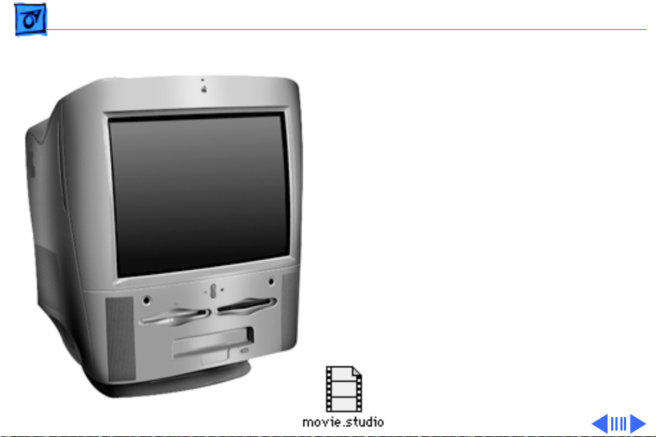
Overview
Introducing the Power
Macintosh G3 All-In-One
design.
• The new all-in-one is
designed for education and
fulfills all the computing
needs of teachers and
students.
• Powerful and easy-to-use
video editing and multimedia
authoring features at an
affordable price.
Click the icon at left for a
QuickTime VR movie of the
Power Mac G3 All-In-One.
Page 4

Basics Overview - 2
Features of the Power Macintosh G3 All-In-One include
• PowerPC G3 microprocessor running at 233 MHz or
266 MHz
• RAM expandable to 384 MB in 3 DIMM slots using 64bit wide, 168-pin JEDEC-standard 3.3 V unbuffered
SDRAM DIMMs
• 512K of static RAM used as L2 cache on processor module
• Built-in 2D and 3D hardware graphics acceleration
• PERCH slot to support I/O card
• One modem slot on the I/O card for optional fax/modem
card
• 4 GB or 6 GB ATA hard drive
• 100 MB SCSI Iomega Zip drive
• CD-ROM ATAPI drive at 24X speed
• 1.4 MB SuperDrive
• One SCSI port
• Two GeoPort serial ports
• 10BASE-T Ethernet port
Page 5

Basics Overview - 3
• One ADB port
• Three PCI expansion slots to accept
• three 7-inch PCI cards, or
• three 15 W cards, or
• two 25 W cards, or
• one 15 W card and one 25 W card
• Fan speed thermally controlled
• Energy Saver control panel
• 2 MB video RAM expandable to 6 MB with
3.3 V, 100 MHz or faster SGRAM on a 144-pin small
outline dual inline memory module (SO-DIMM)
Page 6

Basics Overview - 4
Optional Build-to-Order Power Mac All-In-One Features:
• 100 MB SCSI Iomega Zip drive in the expansion bay
• 6 GB hard drive
• 64 MB (using one 64 MB DIMM) or 96 MB (using 1x
32 MB and 1x64 MB DIMM) of memory
• I/O, Audio/Video card
• 10/100 BaseT ethernet card
Page 7

Basics The Cuda Chip - 5
The Cuda Chip
The Cuda is a microcontroller chip. Its function is to
• Turn system power on and off
• Manage system resets from various commands
• Maintain parameter RAM (PRAM)
• Manage the Apple Desktop Bus (ADB)
• Manage the real-time clock
Many system problems can be resolved by resetting the Cuda
chip (see Symptom Charts for examples). Press the Cuda
reset button on the logic board to reset the Cuda chip. (See
“Logic Board Diagram” later in this chapter to locate the
Cuda reset button.) If you continue to experience system
problems, refer to “Resetting the Logic Board” in this
Basics chapter.
Page 8

Basics Resetting the Logic Board - 6
Resetting the Logic Board
Resetting the logic board can resolve many system problems
(refer to “Symptom Charts” for examples). Whenever you
have a unit that fails to power up, you should follow this
procedure before replacing any modules.
1 Unplug the computer.
2 Remove the battery from the logic board.
3 Disconnect the power supply cable from the logic board
and then press the Cuda Reset button. (See “Logic
Board Diagram” later in this chapter to locate the Cuda
Reset button.)
4 Wait at least 10 minutes before replacing the battery.
5 Make sure the battery is installed in the correct +/-
direction.
Page 9

Basics Resetting the Logic Board - 7
6 Reassemble the computer and test the unit.
Note:
This procedure resets the computer’s PRAM. Be sure
to check the computer’s time/date and other system
parameter settings afterwards.
Page 10

Basics Sound - 8
Sound
The sound system for the Power Macintosh G3 computers is
implemented entirely on the I/O card. Each supports 16-bit
stereo sound output and input, available simultaneously.
The sound circuitry on the I/O card and system software can
create sounds digitally and either play the sounds through
speakers inside the enclosure or send the sound signals out
through the sound output jacks. The sound circuitry digitizes
and records sound as 16-bit samples. The computer can use
22.050K or 44.100K samples per second. The sound system
plays samples at the sampling rate specified in the Monitors
& Sound control panel.
Page 11

Basics Sound - 9
The Power Macintosh G3 also records sound from several
sources:
• A microphone connected to the line-level sound input
jack
• A compact disc in the CD-ROM player
• Analog sound from the cross-platform card in a PCI slot
• Analog sound from optional communication cards
• Internal Microphone
With each sound input source, sound playthrough can be
enabled or disabled.
Page 12

Basics Sound - 10
Sound Output
All sound output features for the Power Macintosh G3
computer are provided by the I/O card. The I/O card
provides one mini jack for sound output on the back of the
enclosure.
The output jacks are connected to the sound amplifier. The
mini jack is intended for connecting a pair of headphones or
amplified external speakers. There are two speakers and two
headphone jacks on the front of the system. Inserting a plug
into the sound output mini jack disconnects the internal
speaker.
Page 13

Basics Sound - 11
Sound Input
The I/O card provides a stereo sound input jack on the back
of the enclosure for connecting an external Apple PlainTalk
line-level microphone or other sound source pair of linelevel signals. The sound input jack accepts a standard 1/8inch stereophonic phone plug (two signals plus ground).
Note:
The microphone for the Macintosh LC and LC II does
not work with the I/O cards.
Options in the Monitors & Sound control panel determine the
interaction between the sound input and output devices. The
sound circuitry normally operates in one of three modes:
• Sound playback—computer-generated sound is sent to the
speaker and the sound output jacks.
• Sound playback with playthrough—computer sound and
sound input are mixed and sent to the speakers and sound
output jacks.
Page 14

Basics Sound - 12
• Sound record with playthrough—input sound is recorded
and also sent to the speakers and sound output jacks.
Page 15

Basics PowerPC G3 and Backside Cache - 13
PowerPC G3 and Backside Cache
Backside cache is a significant architectural design change
from earlier PowerPC processors. The main advantage of the
backside cache architecture is the speed of the dedicated
CPU-to-L2 cache interface. Using the dedicated bus allows
the CPU to access the fast L2 cache storage through a high
speed bus without addressing the slower system bus or
competing with other devices attached to the system bus. In
comparison, a “far-side” cache running on the system bus
would limit that SRAM interface to 50MHz.
The PowerPC G3 microprocessor interfaces with SRAM
storage via a dedicated bus running at various multiples of
the core PLL CPU speed. With high speed L2 SRAM and a
dedicated L2 bus, the CPU can access stored information up
to the speed of the processor clock. L2 access is determined
by the clock ratio setting. For example, with a 250MHz
Page 16

Basics SDRAM DIMMs - 14
PowerPC G3, and a 2.5 L2 bus ratio, the backside cache bus
speed will be 100MHz, twice the speed of the system bus.
SDRAM DIMMs
Three DRAM expansion slots on the logic board accept 3.3 V
SDRAM unbuffered 8-byte DIMMs. The 168-pin DIMM has a
64-bit-wide data bus per bank. The minimum bank size
supported on the Power Macintosh G3 all-in-one model is 4
MB, and the largest is 64 MB. The largest DIMM supported
is a two-bank DIMM of 64 MB using 32 Mbit SDRAM
devices.
The Power Macintosh G3 All-In-One logic board supports a
maximum DRAM expansion of 384 MB. Fill all three slots
with 128 MB DIMMs.
Page 17

Basics SDRAM DIMMs - 15
The DRAM DIMMs can be installed one or more at a time. The
logic board supports only linear memory organization.
Therefore, no performance gains are seen when two DIMMs
of the same size are installed. Any supported size DIMM can
be installed in any DIMM slot, and the combined memory of
all the DIMMs installed will be configured as a contiguous
array of memory.
Important:
DIMMs. DIMMs from older Macintosh computers are not
compatible and should not be used even though they fit into
the DRAM DIMM slots.
Power Macintosh G3 computers use SDRAM
Page 18

Basics SGRAM Video Memory - 16
SGRAM Video Memory
The Power Macintosh G3 logic board comes with 2 MB of
Synchronous Graphic RAM (SGRAM) video memory soldered
on. The logic board also contains a video memory expansion
slot that accepts a Small Outline DIMM (SO-DIMM) to
increase video memory up to a maximum of 6 MB. Apple
supports a 4 MB SGRAM SO-DIMM that is 32-bit wide,
144-pin, fast-paged, 100 MHz/10 ns cycle time or faster.
Important:
or 512K video memory DIMMs used in older Macintosh
computers.
Use only SGRAM SO-DIMMs. Never use the 256K
Page 19

Basics DIMM Slots - 17
DIMM Slots
DRAM
DIMM
Slots
Video Memory Expansion Slot
SGRAM SO-DIMM
ROM Slot
(Do not remove
the ROM DIMM.)
Page 20

Basics - 18
Peripheral Component Interconnect
(PCI)
The Peripheral component Interconnect (PCI) expansion
slots accept 7-inch PCI cards. Install only expansion cards
that come with Macintosh drivers and are compliant with the
PCI 2.1 standard. Nubus™ cards cannot be used in these
expansion slots.
PCI offers significantly higher performance than the NuBus
architecture used in previous Macintosh models. Running at
33 MHz, the PCI bus is up to three times faster than NuBus,
offering overall enhanced system performance, particularly
in the areas of video and networking.
Page 21
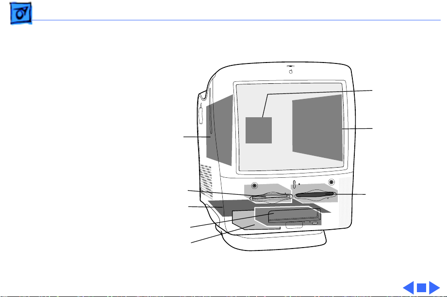
Basics Internal Locator - 19
Internal Locator
Video Board
Analog Board
Zip Drive
Logic Board
CD-ROM Drive
Hard Drive
Power Supply
Floppy Drive
Page 22
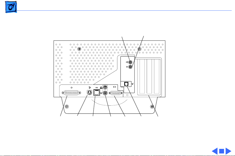
Basics Rear View - 20
Rear View
SCSI
Port
Apple
Desktop
Bus
(ADB)
Port
Sound Output Port
Ethernet
(10Base-T)
Port
Printer
External
modem
Port
&
Monitor
Port
Sound Input Port
Card
Port
Access
Covers for
Expansion
Slots (3)
Internal
Modem
See next page for
optional AV card.
Page 23
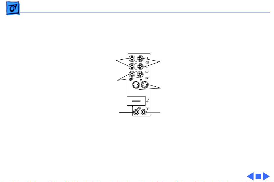
Basics Optional AV Card - 21
Optional AV Card
Audio output ports
(right & left)
Composite Video Ports
(OUT and IN)
Sound Output Port
Audio Input Ports
(right & left)
S-Video Ports
(OUT and IN)
Sound Input Port
Optional AV ports
Page 24
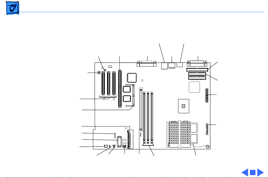
Basics Logic Board - 22
Logic Board
Power Supply
Jumper Block
Cuda Reset Button
PERCH
Slot
Ethernet
Port
Monitor
Port
Serial
Ports
ADB
Port
SCSI
Port
Internal SCSI
Connector
IDE Connector
PCI
Slots
Video Memory
SO DIMM
Voltage Regulator
Processor Jumper Block
Battery
LED
Speaker
Power
On/Off
CD
Audio
ROM
DIMM
DRAM
DIMM
Power Supply
Connector
Floppy Drive
Connector
Microprocessor
Page 25

Basics Repair Strategy - 23
Repair Strategy
Service the Power Macintosh G3 computers through module
exchange and parts replacement. Customers can request onsite service from an Apple Authorized Service Provider Plus
(AASP+), Apple Assurance (US only), or Apple Canada
Technical Answerline (Cananda only). They can also choose
carry-in service from an AASP.
Ordering
Apple Service Providers planning to support the computer
systems covered in this manual may purchase Service
modules and parts to develop servicing capability. To order
parts, use the AppleOrder (US only) or ARIS (Canada only)
system and refer to the Power Macintosh G3 “Service Price
Pages.”
Page 26

Basics Repair Strategy - 24
Large businesses, universities, and K-12 accounts must
provide a purchase order on all transactions, including
orders placed through the AppleOrder (US only) or ARIS
(Canada only) system.
USA Ordering
US Service providers not enrolled in AppleOrder may fax
their orders to Service Provider Support (512-908-
8125) or mail them to
Apple Computer, Inc.
Service Provider Support
MS 212-SPS
Austin, TX 78714-9125
For US inquiries, please call Service Provider Support at
800-919-2775 and select option #1.
Page 27

Basics Repair Strategy - 25
Canadian Ordering
Canadian Service providers not enrolled in ARIS may fax
their orders to Service Provider Support in Canada (1800-903-5284). For Canadian inquiries, please call
Service Provider Support at 905-513-5782 and select
option #3.
Page 28

Basics Warranty/AppleCare/ARIS - 26
Warranty/AppleCare/ARIS
US Only
The Power Macintosh G3 computers are covered under the
Apple One-Year Limited Warranty. The AppleCare Service
Plan is also available for these products. Service Providers
are reimbursed for warranty and AppleCare repairs made to
these computers. For pricing information, refer to “Service
Price Pages.”
Canada Only
The Power Macintosh G3 computers are covered under
AppleCare. The Extended AppleCare Service Plan is also
available for these products. Service Providers are
reimbursed for warranty and AppleCare repairs made to
these computers. For pricing information, refer to “Service
Price Pages.”
Page 29
K
Service Source
Specifications
Power Macintosh G3 All-in-One
Page 30

Specifications Introduction - 1
Introduction
Specifications information for this product can be found in the Spec Database, which you
can access at Service Source Online (http://service.info.apple.com) or on Service Source
CD.
Spec Database at Service Source Online
From the Service Source Online home page, click Troubleshoot and Repair to access the
main repair procedures page. Then click either Apple Spec in the navigation table in the
upper right corner of the page, or click Apple Spec Database from the list of reference tools
below.
Spec Database on Service Source CD
Open the CD and double-click the Apple Spec Database alias located at the top level of the CD.
Page 31

K
Service Source
T ak e Apart
Power Macintosh G3
All-In-One
Page 32

Take Apart Chassis Carrier - 1
Chassis Carrier
No preliminary steps are
required before you begin
this procedure.
1 Loosen the four screws.
2 Pull the chassis carrier
half way out of the unit.
Page 33

Take Apart Chassis Carrier - 2
3 Disconnect the front
control panel cable, RGB
cable, main power cable,
and HDA power cable.
Page 34

Take Apart Chassis Carrier - 3
4 Press up on the tabs to
release the chassis
carrier.
5 Pull chassis carrier out
of unit.
Note
: See graphic on next
page showing complete
chassis carrier out of the
unit.
Page 35

Take Apart Chassis Carrier - 4
Note:
Graphic illustrates
modules and support
bracket located in
chassis carrier.
Page 36

Take Apart Hard Drive - 5
Hard Drive
Before you begin, remove
the chassis carrier.
Page 37

Take Apart Hard Drive - 6
1 Disconnect the hard
drive data cable and the
power cable from the
back of the hard drive.
Page 38

Take Apart Hard Drive - 7
2 Pull up the release latch
and slide the hard drive
forward to remove it
from the internal
chassis.
Note:
Be sure to remove
the hard drive from its
carrier before
returning the drive to
Apple.
Page 39

Take Apart Floppy Drive - 8
Floppy Drive
Before you begin, remove
the chassis carrier.
Page 40

Take Apart Floppy Drive - 9
1 Pull up the release
latch, and slide the
floppy drive forward
enough to reach the
floppy cable.
2 Disconnect the cable
from the back of the
floppy drive.
3 Remove the floppy drive
from the unit.
Note:
Be sure to remove
the EMI shield and floppy
drive carrier before
returning the drive to
Apple.
Page 41

Take Apart Zip Drive - 10
Zip Drive
Before you begin, remove
the chassis carrier.
Page 42

Take Apart Zip Drive - 11
1 Pull up the release
latch, and slide the Zip
drive forward enough to
reach the cables.
2 Disconnect the SCSI and
Zip power cables from
the back of the Zip drive.
3 Remove the Zip drive
from the unit.
Note:
Be sure to remove
the EMI shield and Zip
drive carrier before
returning the drive to
Apple.
Page 43

Take Apart Adding a Zip Drive - 12
Adding a Zip Drive
There may be requests to add a zip drive
to a Power Mac G3 All-in-one
computer. Some prebuilt and build-toorder configurations do not include a
zip drive. Therefore, customers may
want to upgrade their systems by
installing a zip drive taken from
another computer, or by purchasing the
individual service parts.
See the Additional Procedures section
for instructions.
Page 44

Take Apart CD-ROM - 13
CD-ROM
Before you begin, remove
the chassis carrier.
08
Page 45

Take Apart CD-ROM - 14
1 Position the chassis
carrier on its side.
2 Disconnect the CD-ROM
power cable, CD-ROM
SCSI cable, and CD-ROM
audio cable from the
back of the CD-ROM
drive.
Page 46

Take Apart CD-ROM - 15
3 Pull down on the plastic
frame while squeezing
the latch. Slide the CDROM drive forward to
remove it from the unit.
Note:
Be sure to remove
the EMI shield and CDROM carrier before
returning the drive to
Apple.
Page 47

Take Apart CD-ROM - 16
Replacement Note:
removed the CD-ROM cables
from the chassis you will
need to reposition them
before connecting the CDROM drive.
1 Tuck the CD-ROM power
cable, the CD-ROM SCSI
cable, and the CD-ROM
audio cable through the
hole in the plastic
chassis.
2 Reconnect the cables to
the CD-ROM drive.
3 Push CD-ROM into the
chassis until it clicks
into position.
If you
Page 48

Take Apart I/O Card - 17
I/O Card
Before you begin, remove
the chassis carrier.
Page 49

Take Apart I/O Card - 18
1 Disconnect cables on the
I/O Card.
2 Remove two screws that
secure card to chassis.
Note:
Be careful of the
voltage regulator when
removing or replacing
the I/O card.
Page 50

Take Apart I/O Card - 19
3 Remove external I/O
screw on chassis.
Page 51

Take Apart I/O Card - 20
4 Gently rock the I/O card
out of the socket.
5 Remove card from logic
board.
Replacement Note:
back end (end nearest
voltage regulator) of I/O
card and push card down into
slot. Be careful not to
damage the voltage
regulator or modem.
Line up
Page 52

Take Apart Cable Support Bracket - 21
Cable Support Bracket
Before you begin remove
the chassis carrier.
Page 53

Take Apart Cable Support Bracket - 22
1 Disconnect the SCSI
cable and the two IDE
cables on the logic board.
Page 54

Take Apart Cable Support Bracket - 23
2 Remove screw on cable
support bracket.
3 Open white plastic cable
retainer and remove
gray cables from the
support bracket.
4 Lift the metal support
bracket out of unit.
Page 55

Take Apart Logic Board - 24
Logic Board
Before you begin do the
following:
• Remove the chassis
carrier
• Remove I/O card
• Disconnect the SCSI and
IDE cables
• Remove cable clamp
support bracket
Caution
precautions in Bulletins/
Safety.
: Review the ESD
Page 56

Take Apart Logic Board - 25
1 Disconnect the floppy
drive cable.
2 Pull the Zip drive out a
bit to disconnect the Zip
drive power cable.
3 Disconnect the CD-Audio
cable (located next to
battery).
Page 57

Take Apart Logic Board - 26
4 Remove the two silver
screws.
Note
: Do not remove
ground wire from the
heatsink.
Page 58

Take Apart Logic Board - 27
5 Gently lift the logic
board out of the chassis
carrier.
Replacement Note:
logic board requires that
jumper J28 be set properly
for the unit to function. The
power supply jumper, which
installs at J28, should cover
the pins marked "Mac" when
a new board is installed.
This
Page 59

Take Apart CRT EMI Shield - 28
CRT EMI Shield
±
12
Warning:
contains high voltage and a
high-vacuum picture tube.
To prevent serious injury,
review CRT safety in
Bulletins/Safety.
Before you begin, do the
following:
• Remove the chassis
carrier
• Remove the top, side, and
rear panel housing
This product
Page 60

Take Apart CRT EMI Shield - 29
1 Remove the six screws
on the EMI Shield.
Note
: The EMI shield has
sharp edges. Be careful
not to cut yourself.
Page 61

Take Apart CRT EMI Shield - 30
2 Lift the shield up,
releasing the shield from
the metal tabs on the
chassis.
3 Remove the shield from
the unit.
Replacement Note
sure the microphone cable is
pulled through the CRT
chassis frame so the EMI
shield doesn’t pinch the
microphone cable.
: Make
Page 62

Take Apart Power Supply - 31
Power Supply
Before you begin do the
following:
• Remove the chassis
carrier
• Remove the top, side, and
rear panel housing
• Remove the CRT EMI
shield
• Discharge the CRT
Page 63

Take Apart Power Supply - 32
1 Push tab in.
2 Lift and pull the power
supply up to clear the
pegs from the chassis
holes.
Note
: The cables are still
attached to the power
supply at this point.
Page 64

Take Apart Power Supply - 33
3 Disconnect the multi-
colored power cable
(P904),the ground wire
(P911), and the 2-pin
brown wire (TH901),
from the power supply.
Page 65

Take Apart Power Supply - 34
4 Tilting the power
supply off to the side,
disconnect the remaining
cables on the power
supply board:
• P912
• P905
• P906
• P913
• P908
Note
: P906 and P908
have locking connectors.
Pinch or squeeze to
release the connectors.
5 Remove power supply
from the chassis.
Page 66

Take Apart Power Supply - 35
Replacement Note
connectors are impossible to
reconnect when the board is
in place. Before inserting
the power supply, connect
cables TH901, P908,
P913, P906, and P905.
Also, make sure the pegs on
the power supply reseat into
the holes in the chassis.
: Some
Page 67

Take Apart Power Supply - 36
Additional cable descriptions:
P912
: Thermistor cable: a 2-wire gray & brown cable that
connects to the brown connector on the power supply board
P905
: Fan cable: a 2-wire red &black cable
P906
: a flat gray ribbon cable (922-3492). This cable is a
wide gray ribbon cable that connects to the I/O card and then
splits off into three cables, one goes to the front panel board,
one to the power supply board (P906), and one to the analog
board (P503).
P913
: a 10-wire gray & blue cable (2 wires from this cable
split off and connect to P4 on the front panel board and the
other end connects to P505 on the analog board)
P908
: a 5-wire gray & blue cable (P908 connects to P507
on the analog board)
Page 68

Take Apart Analog/Video Board - 37
Analog/Video Board
Before you begin do the
following:
• Remove the chassis
carrier
• Remove the top, side, and
rear housing
• Remove the CRT EMI
shield
• Discharge the CRT
• Disconnect anode cap
Page 69

Take Apart Analog/Video Board - 38
1 Disconnect the
microphone (P703),
ground wire (P702),
degaussing wire
(P508), and the yoke
wire (P701).
Page 70

Take Apart Analog/Video Board - 39
2 Gently remove the CRT
video board.
3 Push in tab and lift
analog board out of
chassis holes.
Page 71

Take Apart Analog/Video Board - 40
4 Disconnect P502,
P503, P507, P506, and
P505.
Important
P503, P507, and P506
have clamped (or
locking) connectors.
Pinch or squeeze to
release these connectors.
5 Remove analog/CRT
video board from
chassis.
Note
: See next page for cable
connection information.
: P502,
Page 72

Take Apart Analog/Video Board - 41
On the analog board:
• P502 connects to P305 on the CRT video board
• P503 connects to P906 on power supply
• P505 connects to P913 on the power supply
• P507 connects to P908 on the power supply
• P506 connects to P302 on the CRT video board
Page 73

Take Apart CRT Bezel - 42
CRT Bezel
Before you begin, remove
the following:
• Top, side, and rear panel
housing.
• Front door
Page 74

Take Apart CRT Bezel - 43
1 Remove the two silver
torx screws located on
each side of the CRT.
2 Disconnect the
microphone cable (P11)
from the microphone
board.
3 Pull bezel off the
chassis.
Page 75

Take Apart Speakers - 44
Speakers
Before you begin do the
following:
• Remove the top, side, and
rear panel housing
• Front door
• CRT Bezel
• Front panel board
Page 76

Take Apart Speakers - 45
1 Remove speaker screw.
2 Speaker cable should be
disconnected from sound
board; gently pull
speaker cable out from
underneath the CRT.
3 Slide the speaker
forward to remove it
from the chassis.
4 Repeat steps 1-3 to
remove opposite
speaker.
Page 77

Take Apart Front Panel Board - 46
Front Panel Board
Before you begin do the
following:
• Remove the top, side and
rear panel housing
• Front door
• CRT bezel
1 Remove two screws.
Page 78

Take Apart Front Panel Board - 47
2 Pull front panel board
forward to disconnect
the three cables and
ribbon connector.
3 Remove front panel
board from chassis.
Page 79

Take Apart CRT - 48
CRT
±
Warning: This product
contains high voltage and a
high-vacuum picture tube.
To prevent serious injury,
review CRT safety in
Bulletins/Safety.
Before you begin do the
following:
• Remove the chassis
carrier
• Remove the top, side, and
rear panel housing
• Remove the CRT EMI
shield
• Discharge the CRT
Page 80

Take Apart CRT - 49
• Remove the analog board
• Remove the power supply
• Remove the front door
• Remove the CRT bezel
• Remove front panel board
Page 81

Take Apart CRT - 50
1 Remove the screws that
secure the clips.
2 Remove clips.
Page 82

Take Apart CRT - 51
3 Remove two screws that
secure the CRT frame to
the main chassis.
Page 83

Take Apart CRT - 52
4 Securely hold CRT and
lift CRT off the chassis.
Page 84

Take Apart CRT - 53
Replacement Note: Position
bottom of CRT so the CRT
frame connects with the four
chassis catches under the
front of the CRT.
Continue lowering the CRT
frame onto the main
chassis. Squeeze the rear of
the CRT chassis frame
inward so it fits inside
chassis catches on either
side.
Attach screw (one on other
side also) where black
arrow is pointing.
Page 85

Take Apart Fan - 54
Fan
Before you begin, do the
following:
• Remove the chassis
carrier.
• Remove the top, side, and
rear panel housing.
• Remove the CRT EMI
shield
• Discharge the CRT
• Remove the analog board
• Remove the power supply
Page 86

Take Apart Fan - 55
1 Position hand inside
chassis to catch fan as it
drops down when the
two fan screws are
removed.
2 Remove fan from
chassis.
Page 87

Take Apart Thermistor - 56
Thermistor
Before you begin, do the
following:
• Remove the chassis
carrier.
• Remove the top, side, and
rear panel housing.
• Remove the CRT EMI
shield
• Discharge the CRT
• Remove the analog board
• Remove the power supply
Page 88

Take Apart Thermistor - 57
1 Remove screw on
thermistor bracket.
2 Remove bracket;
remove thermistor.
Page 89

Take Apart Chassis w/ Cables - 58
Chassis w/ Cables
Before you begin do the
following:
• Remove the chassis
carrier
• Remove the top, side, and
rear housing
• Remove the CRT EMI
shield
• Discharge the CRT
• Remove the analog board
• Remove the power supply
• Remove the CRT bezel
• Remove the front door
• Remove the CRT
• Remove fan and
thermistor
Page 90

Take Apart Chassis w/ Cables - 59
• Remove Tilt /Swivel Base
The chassis and three cables
remain. The chassis with
cables is part number 922-
3489.
Note: These cables are
available separately:
– Main power cable
(922-3481)
– RGB cable (922-
3480)
– Cable to I/O, front
panel, analog, p/s
(922-3492)
Page 91

Take Apart Processor Module - 60
Processor Module
Before you begin, do the
following:
• Remove the chassis
carrier
• Remove I/O card
• Remove cable clamp
support bracket
Caution: Review the ESD
precautions in Bulletins/
Safety.
Page 92

Take Apart Processor Module - 61
1 Remove the screw that
holds the processor
module wire to the logic
board.
Replacement Note: The
processor module wire
attaches to the top of the
logic board (not
underneath). When
screwing down the wire, be
careful not to damage the
capacitor that is next to the
screw hole. Use a manual
screw driver to avoid
damaging the capacitor.
Page 93

Take Apart Processor Module - 62
Warning: the heat sink may
be hot to the touch.
2 While pressing down on
the top of the clip that
secures the heatsink, use
a small flatblade
screwdriver to lift up on
the front tab of the clip
to release it.
Page 94

Take Apart Processor Module - 63
3 Lift up the clip and
remove it from the
heatsink.
Page 95

Take Apart Processor Module - 64
4 Lift up the heatsink to
remove it from the
processor module.
Page 96

Take Apart Processor Module - 65
5 Lift the metal lever at
the left of the processor
module.
Page 97

Take Apart Processor Module - 66
6 Pick up the processor
module by the edges and
gently lift straight up to
remove it. Be careful not
to bend the pins
underneath the module.
IMPORTANT: If you are only
replacing the processor
module, stop here. If,
however, you are removing
the processor module in
order to replace the logic
board, continue on to the
next page.
Replacement Note: Don’t
force the processor module.
Page 98

Take Apart Processor Module - 67
7 Remove the warranty
sticker and red jumper
block located next to the
battery if replacing the
logic board only.
IMPORTANT: When
replacing the processor
module, you must change the
processor jumper block and
warranty sticker to be
compatible with the processor module you are installing. Failure to install the
jumper block properly will
result in a unit that does not
power on. See the instructions on the following page.
Page 99

Take Apart Processor Module - 68
8 Install the jumper as
shown. Depending on the
computer’s processor
speed, you will install a
red jumper (233 MHz)
or a white jumper (266
Processor
Jumper Block
MHz). Be sure to cover
the pins as shown and to
install the jumper block
with the gold connector
pins facing down towards
the board.
233 MHz
Red
266 MHz
White
Battery
Replacement Note:
Position the processor
module over the slot, seat it
evenly, and press down
gently on the module to
Page 100

Take Apart Processor Module - 69
install it. Never force the
module or you may damage
the gold connector pins on
the underside. Flip down the
metal lever that secures the
module to the board.
Install a gap filler, 9223643, on a new processor.
Replace the heatsink, insert
the clip onto the tab at the
rear of the module, swing
the clip over the heatsink,
and secure the front latch.
 Loading...