

Page 1

Service Source
PowerBook G4 (15-inch Double-Layer SD)
19 October 2005
© 2005 Apple Computer, Inc. All rights reserved.
Page 2
Service Source
Basics
PowerBook G4 (15-inch Double-Layer SD)
© 2005 Apple Computer, Inc. All rights reserved.
Page 3
General Information
Overview
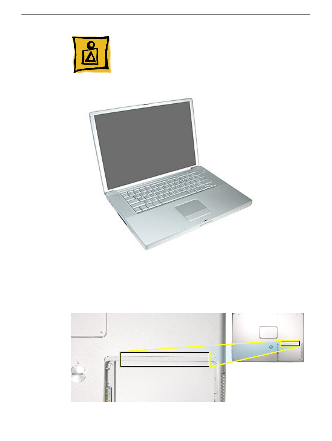
From the exterior, the PowerBook G4 (15-inch Double-Layer SD) physically is identical to
its predecessor, the PowerBook G4 (15-inch 1.67/1.5GHz). Both lack the customer
accessible AirPort door in the battery bay.
General Information
PowerBook G4 (15-inch Double-Layer SD) Basics - 1
Page 4
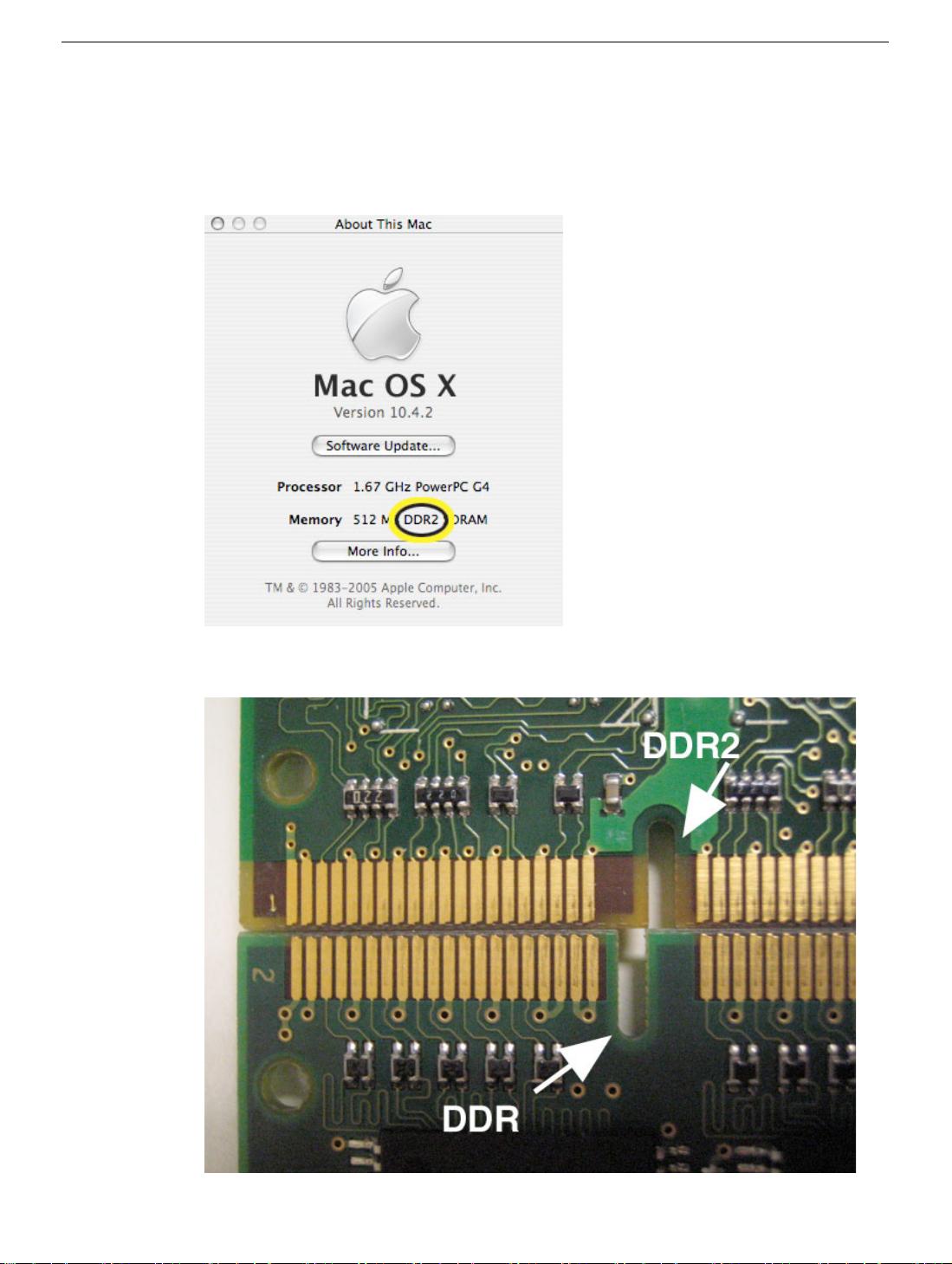
The quickest ways to identify the PowerBook G4 (15-inch Double-Layer SD) computer:
• If the system is bootable, power it on. After pressing the power button the sleep LED
light comes on solid and stays on until video appears onscreen.
• Also the "About this Mac." Under Memory, shows DDR2 memory.
• Check a memory card to see if it is DDR2 (keyed differently than DDR)
2 -
PowerBook G4 (15-inch Double-Layer SD) Basics
General Information
Page 5
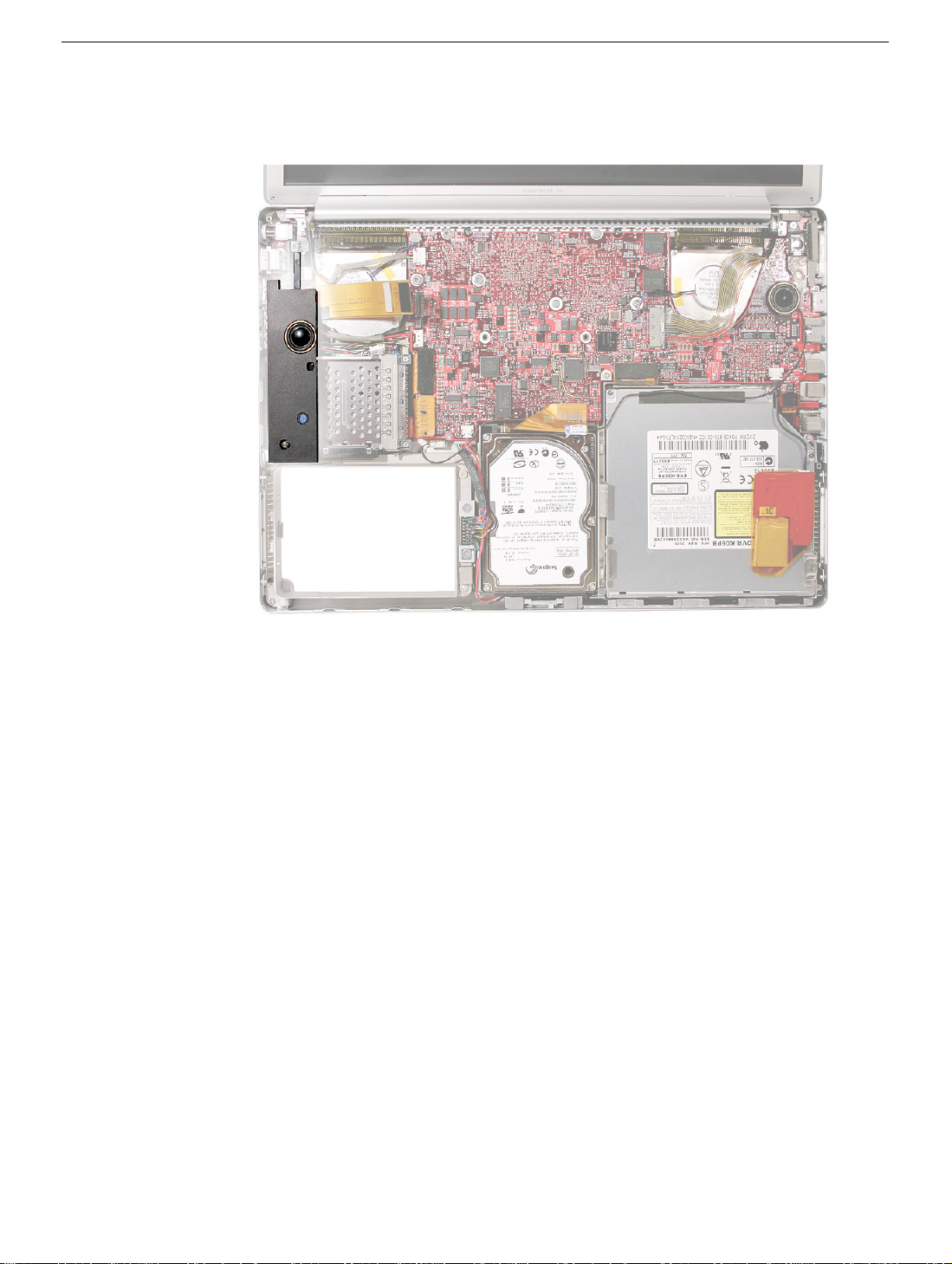
• With the top case removed, there is no mid-range speaker module (which has been
above the hard drive on all previous aluminum PowerBook G4 15-inch models).
Main feature differences from the previous models:
• Higher resolution 15.2-inch display, 1440 x 960, 114 dpi (previously 1280 x 854, 101
dpi)
• Supports DDR2 memory up to 2GB
• 128MB VRAM with dual link DVI option is now standard
• Double-Layer SuperDrive allows users to burn two layers through a single side of a
double-layer burnable disc.
• 80GB 5400 RPM hard drive standard
• 100GB/120GB 5400 RPM, 100GB 7200 RPM hard drive option
Some key features common to the two previous models that distinguish these
computers from earlier PowerBook models, include:
• Aluminum alloy enclosure
• Built-in FireWire 800 port
• Supports USB 2.0
General Information
PowerBook G4 (15-inch Double-Layer SD) Basics - 3
Page 6

New Parts and Procedures
• Main Battery
– The main battery has a new capacity sensing circuit design. It looks the same as
previous batteries and is interchangeable. However, it has a different battery
calibration procedure. A new calibration procedure has been developed which works
on both batteries. Look in the Troubleshooting section, Battery Short Life for details.
This change does not apply to the PowerBook G4 17-inch.
• Top Case
– As the sleep magnet has been relocated to the display bezel, the sleep sensor has
moved from the trackpad flex to the edge of the top case. Previous top cases will not
work with this system.
• Keyboard
– The keyboard has a narrower flex than the previous integrated backlight keyboard
used in the PowerBook G4 (15-inch 1.67/1.5GHz). These two keyboards are not
interchangeable. This keyboard is the same as on the PowerBook G4 (17-inch
Double-Layer SD).
• Mass Storage (Hard drive and optical drive)
– Both devices share a single ATA bus using a cable select addressing scheme.
Previously each drive was a master device on separate ATA busses. Although, an
older hard drive may work in this system, the optical drive will either not show up as
a device or cause the system to not boot-up properly.
• AirPort Extreme and Bluetooth 2.0
– These two functions have been combined on a single card.
– The card has the antenna diversity function built-in, eliminating that card in the clutch
cover.
• Main Logic Board
– A new thermal grease is used. It has a greyish color.
Other minor differences include cable shapes, routing, connector types, locations, screws,
brackets, and part designs.
4 -
PowerBook G4 (15-inch Double-Layer SD) Basics
General Information
Page 7
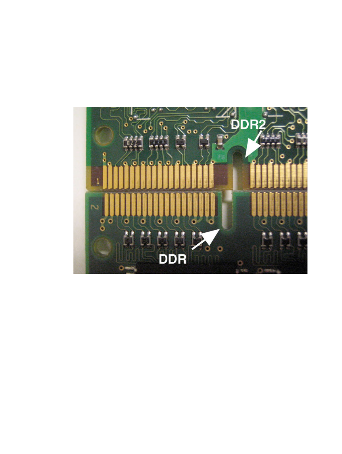
Important Memory Note
Memory from previous 15-inch (Titanium-series) PowerBooks is not compatible with this
computer.
Memory from previous PowerBook G4 (15-inch FW800), PowerBook G4 (15-inch 1.5/
1.33GHz), and PowerBook G4 (15-inch 1.67/1.5GHz) is physically not compatible. DDR2
is keyed differently than DDR memory.
Service Manual Note
In this manual, graphics or photos are intended to help illustrate procedures or
information, only, and may show a different level of disassembly, or show a different
configuration or computer model, than your computer.
Kapton® Tape Note
See Kapton Tape topic below.
Cable Routing Note
During disassembly, note cable routing. Reassemble in the same manner. Verify that
cables do not route over components when they should route into lower positions or
channels. Verify that the cables are not strained or applying pressure onto other
components.
General Information
PowerBook G4 (15-inch Double-Layer SD) Basics - 5
Page 8
Tools
The following tools are recommended for the take apart procedures.
• ESD wrist strap and mat
• Soft cloth
• #0 Phillips screwdriver (magnetized)
• #1 Phillips screwdriver (magnetized)
• 5 mm socket wrench
• 1.5 mm Hex key (or Torx T6)
• Needlenose pliers
• Torx T8 screwdriver
• Torx T6 screwdriver
• Thermal grease (922-7144)
• Gasket kit (076-1201)
• Alcohol pads
• Black stick (nylon probe tool 922-5065) (or other nonconductive nylon or plastic flatblade tool)
• Multi-compartment screw tray (such as a plastic ice cube tray)
• Kapton tape (922-1731 (0.5-inch x 12-yard roll))
• Apple Pro keyboard and mouse (for troubleshooting)
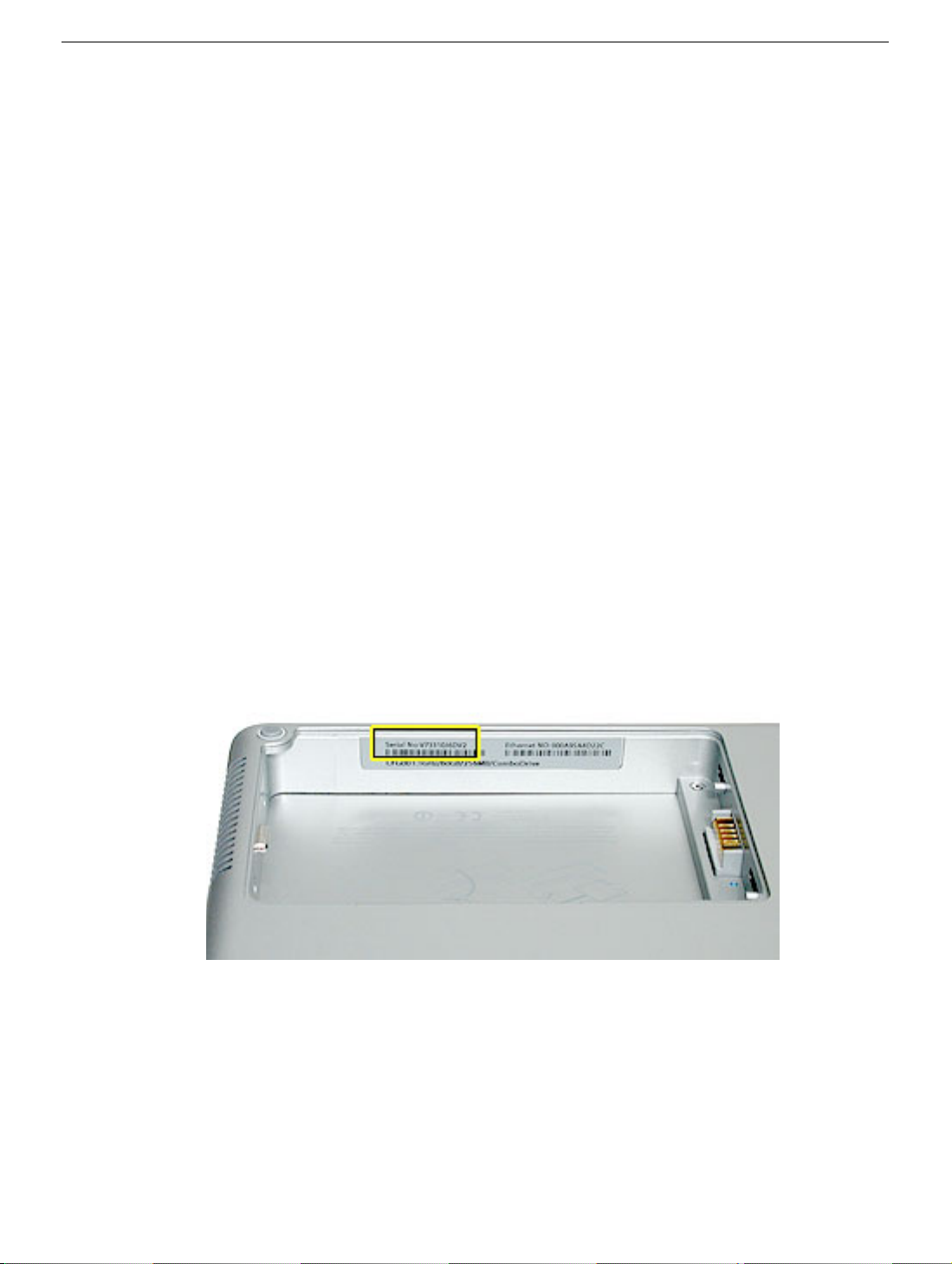
Serial Number Location
The serial number is located in the battery bay.
6 -
PowerBook G4 (15-inch Double-Layer SD) Basics
General Information
Page 9
Kapton Tape
Tools
This procedure requires the following tools:
• Kapton tape (922-1731 (0.5-inch x 12-yard roll))
• Scissors or tape dispenser
Procedure
Kapton tape is used to secure cables and connectors where necessary.
During disassembly, note any Kapton tape use and locations—reapply in the same
manner. Do not over apply or build up tape on top of old tape; space tolerances are tight
and build up or extraneous use of tape may cause pressure on other components.
Refer to the picture below throughout this manual as a guide to replacing Kapton tape.
Kapton Tape
PowerBook G4 (15-inch Double-Layer SD) Basics - 7
Page 10

Service Source
Take Apart
PowerBook G4 (15-inch Double-Layer SD)
© 2005 Apple Computer, Inc. All rights reserved.
Page 11
Foot
Tools
This procedure requires the following tools:
• Foot kit
• Tweezers or needlenose pliers
• Soft cloth
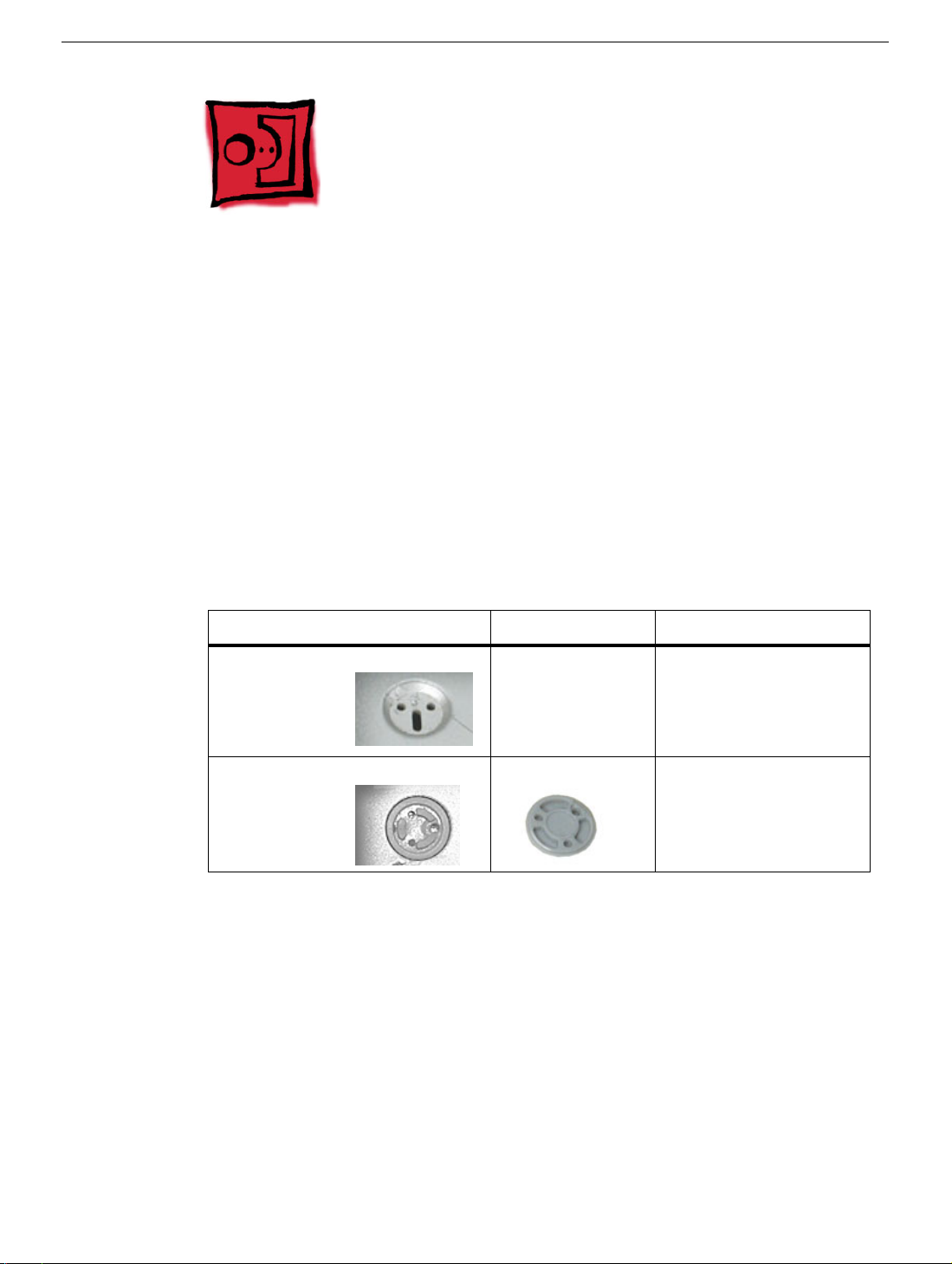
Preliminary Step
Before you begin, check the foot location that needs replacement and verify that the case
plug is attached. Also verify that the case plug, and the case foot in the kit,
pictures below.
Plug Area on Bottom Case Matching Foot Action
Missing case plug Not available for
replacement
Case plug Case foot Continue with the
Replace the bottom
case, or send to Apple
Repair Center.
procedure, matching
the foot to the plug on
the bottom case.
match the
Foot
PowerBook G4 (15-inch Double-Layer SD) Take Apart -
1
Page 12

Procedure
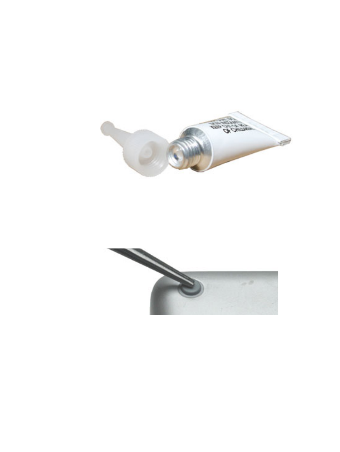
Warning:
glue. In the event of contact, review the safety instructions at the end of this document. For
additional information, refer to the glue manufacturer:
1. Place the computer upside down on a clean, lint-free cloth or other nonabrasive
2. Select a foot from the kit. Verify that the case plug and case foot match (refer to the
3. Make sure the plug area on the bottom case is clean. If any portion of the soft rubber
The glue used in this procedure can bond instantly to skin. Do not touch the
Elmer's Products, Inc.
Columbus, OH. 43215-3799
www.krazyglue.com
surface.
images shown in the table). Do not use a foot that does not match.
foot remains, remove it so that only the hard plastic plug is visible.
Important:
rubber foot match up and fit into the corresponding indents and bumps in the plug.
This ensures a balanced and level fitting. (Note: The picture below is of a different
foot than on the computer, and is for illustration only.)
When positioning the foot, make sure the indents and bumps of the
2 -
PowerBook G4 (15-inch Double-Layer SD) Take Apart
Foot
Page 13
4.
Warning:
touch the glue at any time. Before opening the glue, review the safety instructions at
the end of this document.
GLUE IS AN EYE AND SKIN IRRITANT. BONDS SKIN INSTANTLY. Do not
Important:
seal until you are ready to use the glue. To break the seal, hold the tube upright and
away from you. Place the hollow nozzle cap on the tube and tighten it all the way
down. The tube is then ready to dispense the glue through the nozzle cap.
5. Apply one drop of glue to the plug on the bottom case. Do not spread the glue.
6. Using tweezers or needlenose pliers, carefully position the new foot so its textured
surface fits into the inner ring of the plug.
7. Using the end of the tweezers or pliers—not your finger—lightly press and hold the
foot in place for 30 seconds.
The glue tube included in the kit is sealed until first use. Do not break the
Foot
8. Before turning over the computer, allow the glue to set for at least 15 minutes.
9. Discard the tube of glue.
SAFETY INSTRUCTIONS:
INSTANTLY. Contains ethyl cyanoacrylate. Avoid contact with skin and eyes. If eye or
mouth contact occurs, hold eyelid or mouth open and rinse thoroughly but gently with
water only for 15 minutes and GET MEDICAL ATTENTION. Liquid glue will sting eye
temporarily. Solidified glue may irritate eye like a grain of sand and should be treated by an
eye doctor. If skin bonding occurs, soak in acetone-based nail polish remover or warm
soapy water and carefully peel or roll skin apart (do not pull). Contact through clothing may
cause skin burn. If spilled on clothing, flush with cold water. Avoid prolonged breathing of
vapors. Use with adequate ventilation. KEEP OUT OF REACH OF CHILDREN.
GLUE IS AN EYE AND SKIN IRRITANT. BONDS SKIN
PowerBook G4 (15-inch Double-Layer SD) Take Apart -
3
Page 14
Battery
Tools
This procedure requires the following tools:
• Soft cloth
• Coin
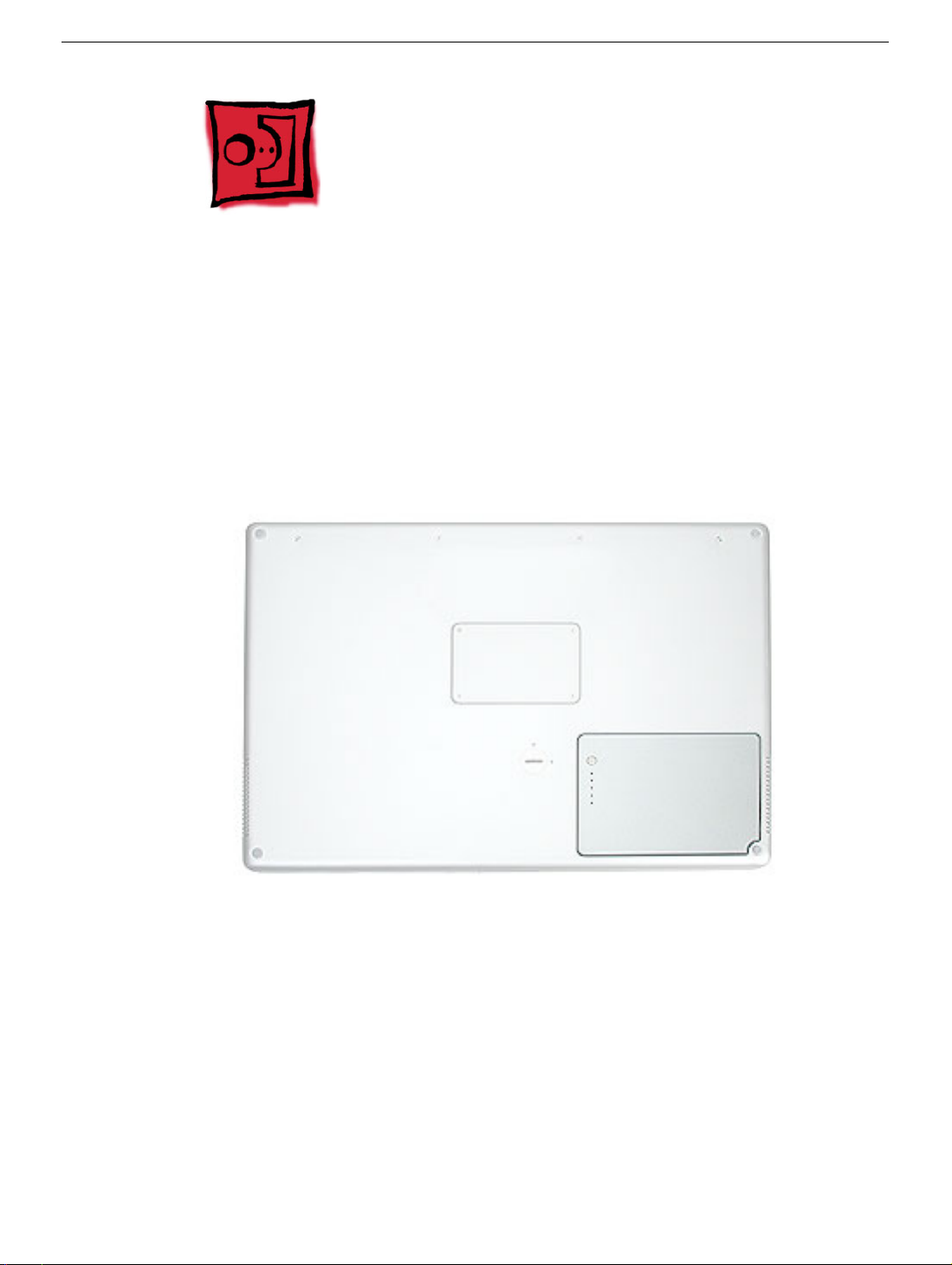
Part Location
Preliminary Steps
Warning: Always shut down the computer before opening it to avoid damaging its
internal components or causing injury. After you shut down the computer, the
internal components can be very hot. Let the computer cool down before
continuing.
4 -
PowerBook G4 (15-inch Double-Layer SD) Take Apart
Battery
Page 15
Procedure
Warning: If the computer has been recently operating, allow it to cool down before
performing this procedure.
1. Shut down the computer.
2. Disconnect the power cord and any other cables connected to the computer.
3. Place the computer face down on a soft cloth.
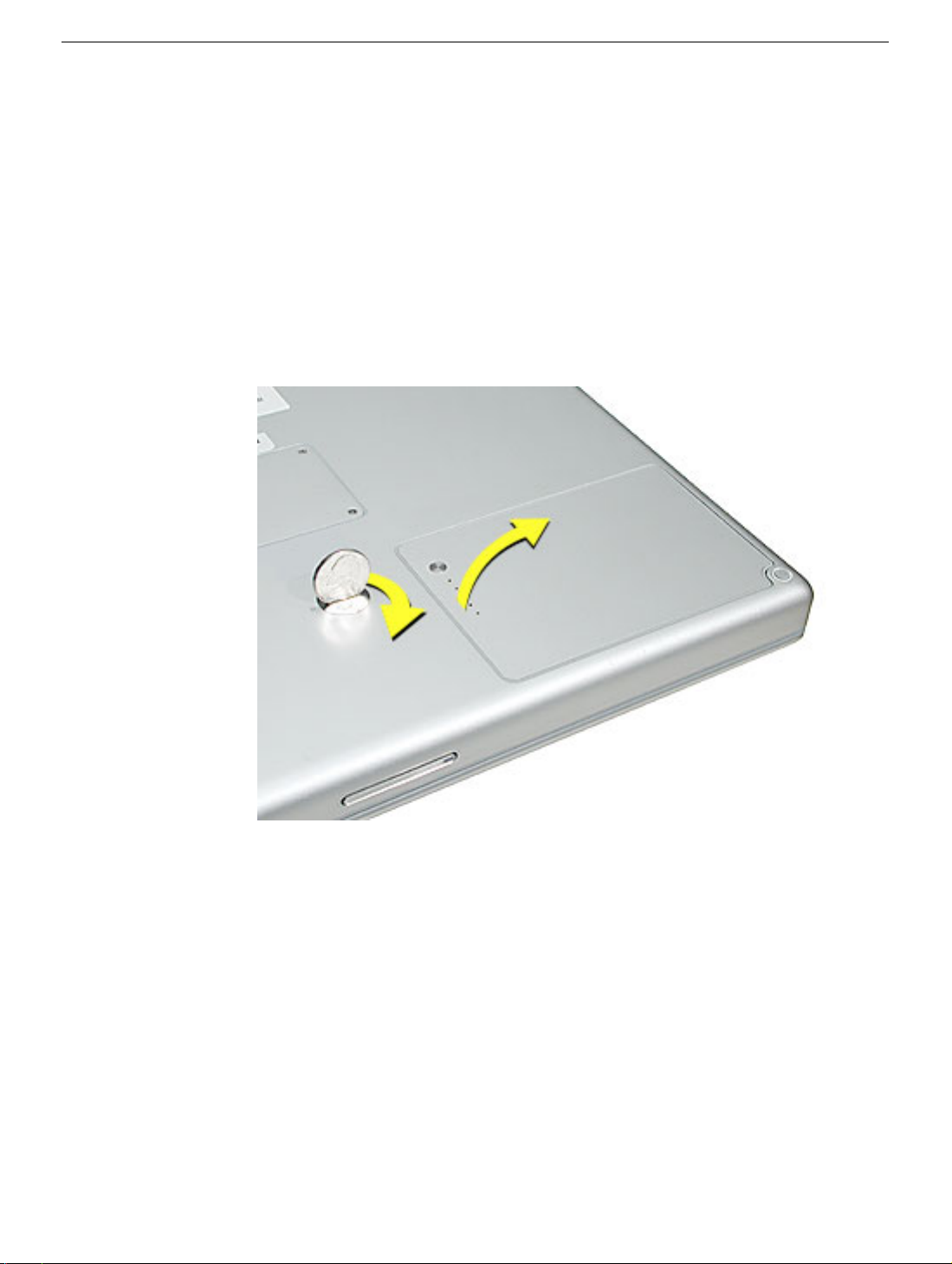
4. Insert a coin in the battery lock slot and turn it one quarter turn clockwise. The battery
should raise up slightly. Lift the battery out of the battery bay.
Battery
PowerBook G4 (15-inch Double-Layer SD) Take Apart -
5
Page 16
Memory Door and Memory Cards
Tools
This procedure requires the following tools:
• Soft cloth
• #0 Phillips screwdriver
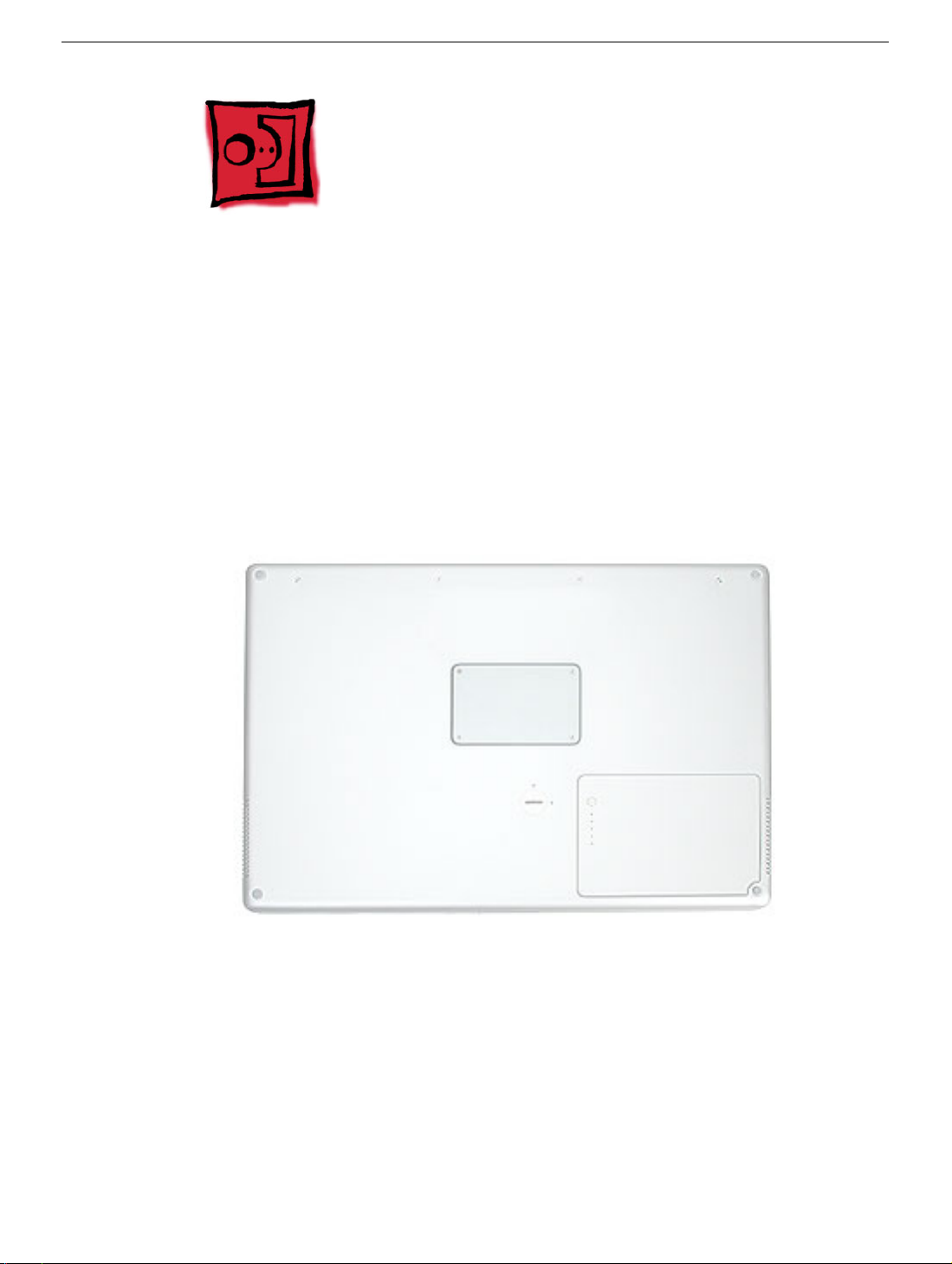
Part Location
Preliminary Steps
Before you begin, remove the battery.
6 -
PowerBook G4 (15-inch Double-Layer SD) Take Apart
Memory Door and Memory Cards
Page 17
922-6091
3.4 mm
Procedure
Warning: If the computer has been recently operating, allow it to cool down before
performing this procedure.
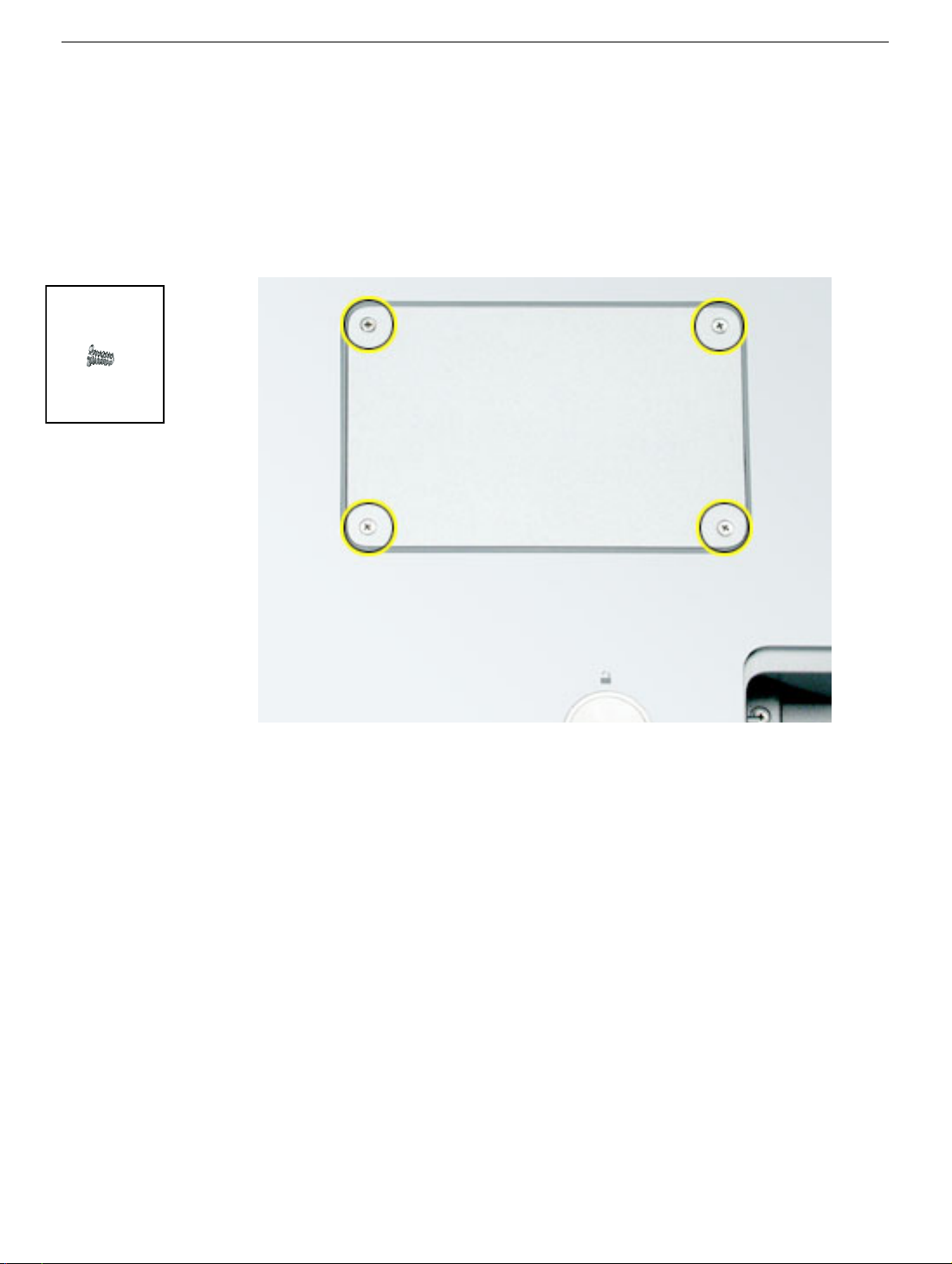
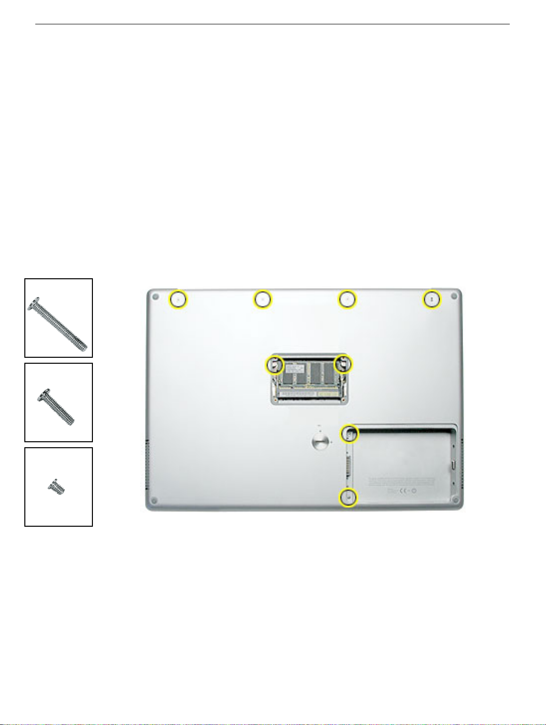
1. Place the computer face down on a soft cloth.
2. Remove the four screws from the memory door then remove the door.
Note:
If only one memory card is installed, the factory installs it in the bottom memory slot.
Note:
Memory must be removed from the top slot before removing from the bottom slot.
Memory Door and Memory Cards
PowerBook G4 (15-inch Double-Layer SD) Take Apart -
7
Page 18
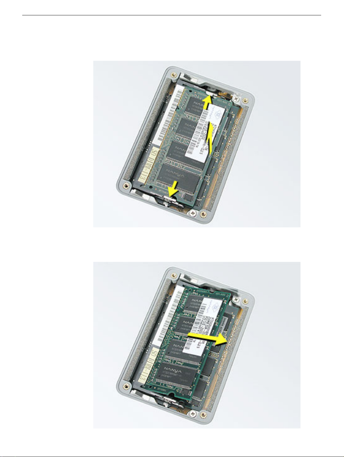
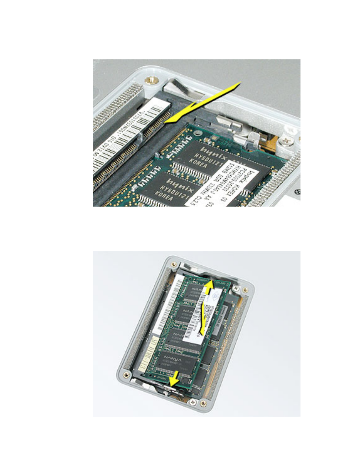
3. To remove memory cards, carefully spread the two locking tabs for the slot (top or
bottom) away from the card on both sides and allow the card to pop up slightly.
4. Pull the card straight back and out of the memory slot.
8 -
PowerBook G4 (15-inch Double-Layer SD) Take Apart
Memory Door and Memory Cards
Page 19
Replacement Procedure
Notes:
• DDR memory cards do not fit in this slot (different notch location).
• The top and bottom memory cards are inserted at different angles.
• If installing two cards, install into the bottom slot first.
• Align the notch in the memory card with the tooth in the slot before inserting.
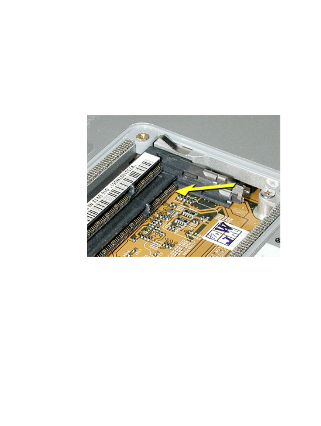
1. To install a memory card into the bottom slot, insert the card at a low angle behind the
locking tabs of the top slot.
Memory Door and Memory Cards
PowerBook G4 (15-inch Double-Layer SD) Take Apart -
9
Page 20
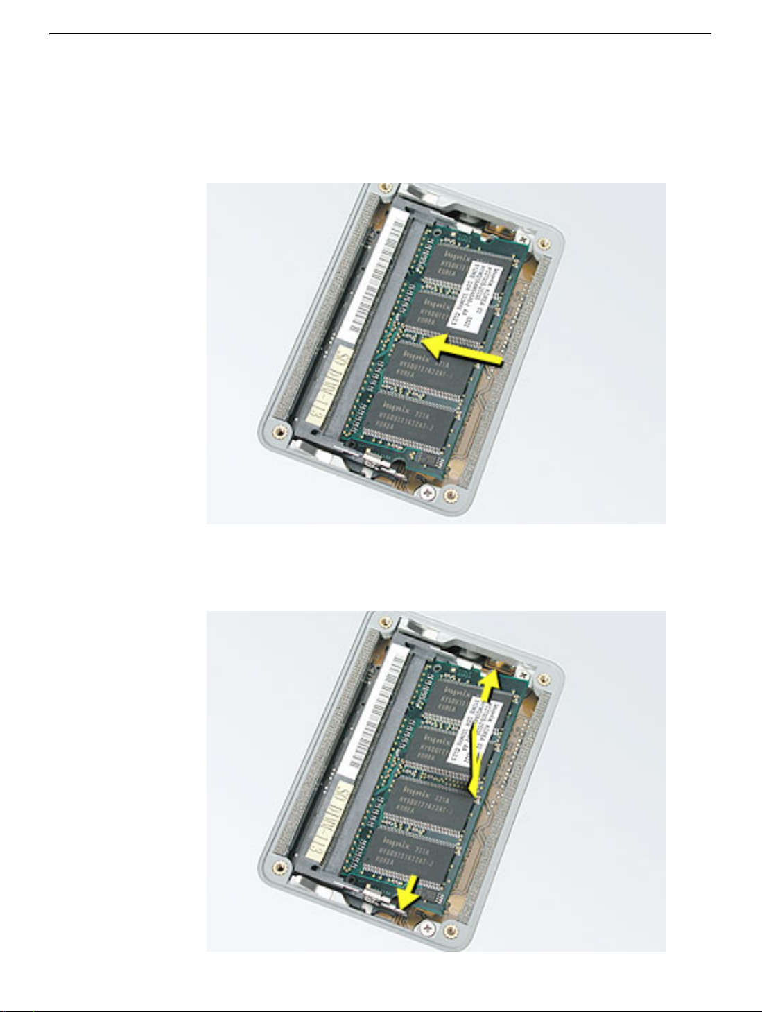
2. Slide the card forward to the lower slot. Firmly push the card straight into the slot until
it is fully and securely seated along its length.
Note:
If the back of the card drops down before it is fully seated, raise it up enough to
push it fully into the slot.
3. Carefully spread the two locking tabs for the bottom slot away from the card on both
sides while pushing the card straight down until the tabs click onto both sides of the
card, locking it into place.
10 -
PowerBook G4 (15-inch Double-Layer SD) Take Apart
Memory Door and Memory Cards
Page 21
4. If installing a memory card in the top slot, follow the same procedures as the bottom
slot except insert the card at a 30-degree angle, above the locking tabs.
5. Push the card in until it is firmly seated.
6. As with the bottom slot, spread the locking tabs for the top slot while pushing the card
straight down until it locks into place.
Memory Door and Memory Cards
PowerBook G4 (15-inch Double-Layer SD) Take Apart -
11
Page 22
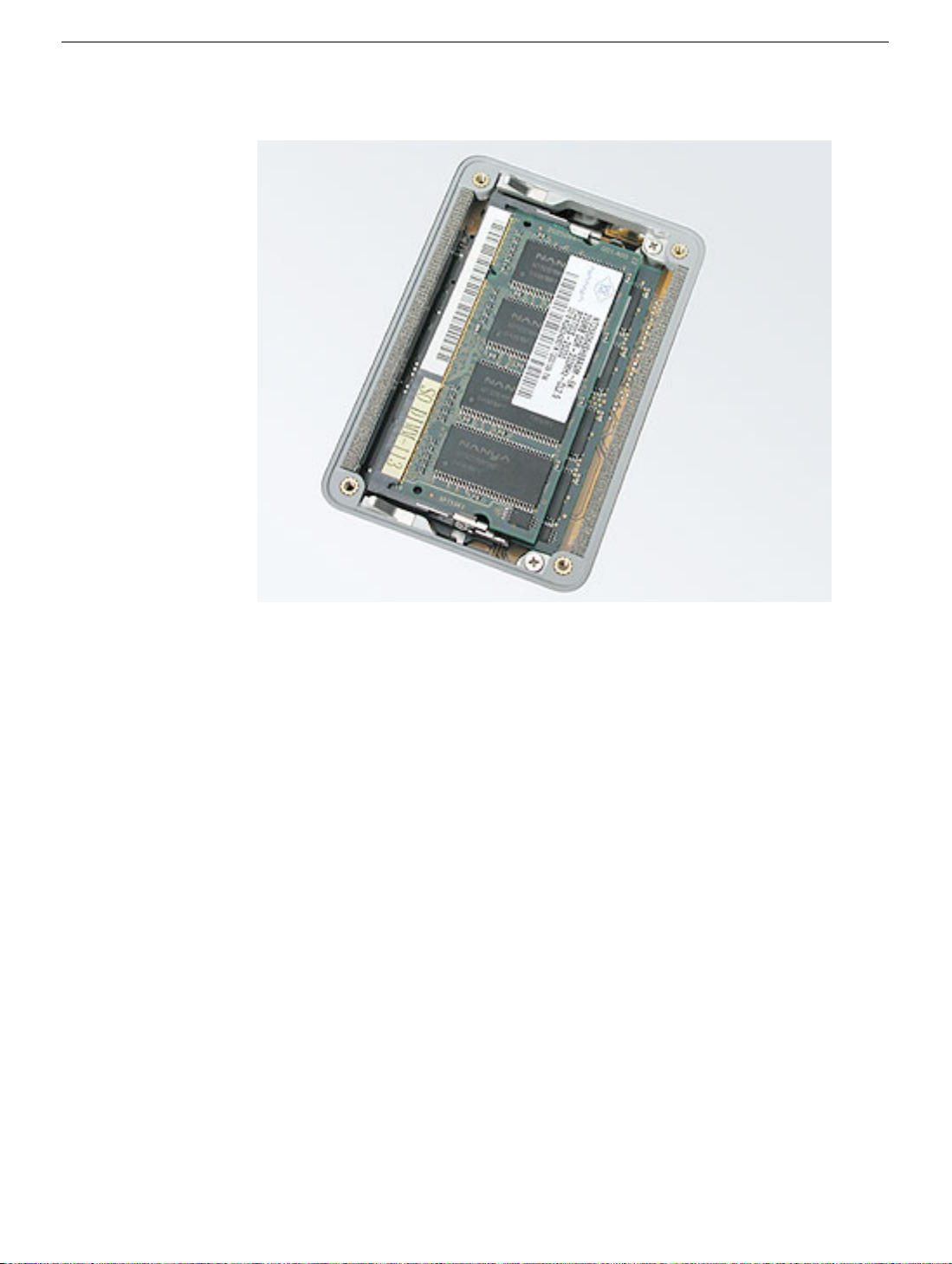
7. Cards should be flat and secure on both sides.
8. Install the memory door.
9. Replace the battery.
10. Use Apple System Profiler to verify that the memory is recognized. (Choose the menu
bar Apple logo (
open the Memory Overview.)
) > About This Mac, click More Info..., select the System Profile tab,
12 -
PowerBook G4 (15-inch Double-Layer SD) Take Apart
Memory Door and Memory Cards
Page 23
Top Case
Tools
This procedure requires the following tools:
• #0 Phillips screwdriver (magnetized)
• 1.5 mm Hex key (or Torx T6)
• Black stick (or other nonconductive nylon or plastic flat-blade tool)
• Soft cloth
• Multi-compartment screw tray
Part Location
Top Case
PowerBook G4 (15-inch Double-Layer SD) Take Apart -
13
Page 24
Preliminary Steps
Before you begin, remove the following:
• Battery
• Memory door
Procedure
Note:
This procedure removes the top case and keyboard assembly. The keyboard is
removable only after removing the top case.
1. Place the computer face down on a soft cloth.
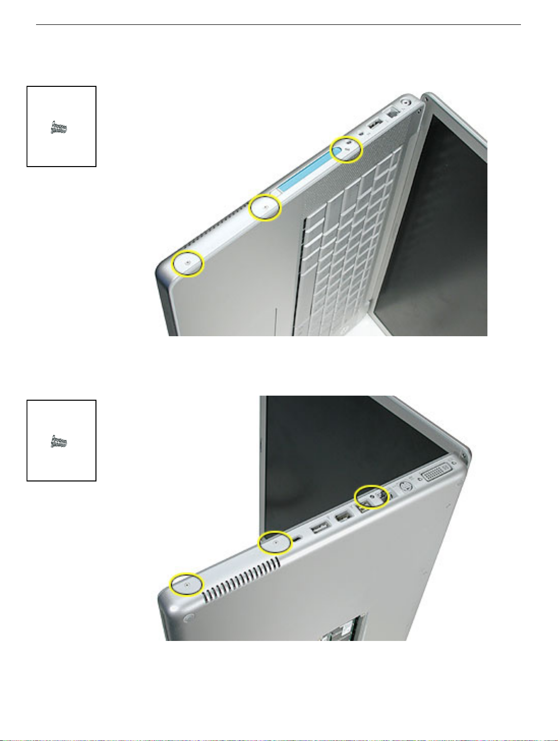
2. Remove the two screws inside the battery bay.
3. Remove the two screws from the memory bay.
4. Remove the four screws along the back edge.
922-6095
16.4 mm
922-6719
12.6 mm
922-6091
3.4 mm
14 -
PowerBook G4 (15-inch Double-Layer SD) Take Apart
Top Case
Page 25
922-6091
3.4 mm
5. With the display open, rest the computer on one side. Remove the three screws.
922-6091
3.4 mm
6. Turn over the computer and remove the three screws on the other side.
Top Case
PowerBook G4 (15-inch Double-Layer SD) Take Apart -
15
Page 26
922-6100
5.3 mm
922-6096
1.5 mm Hex
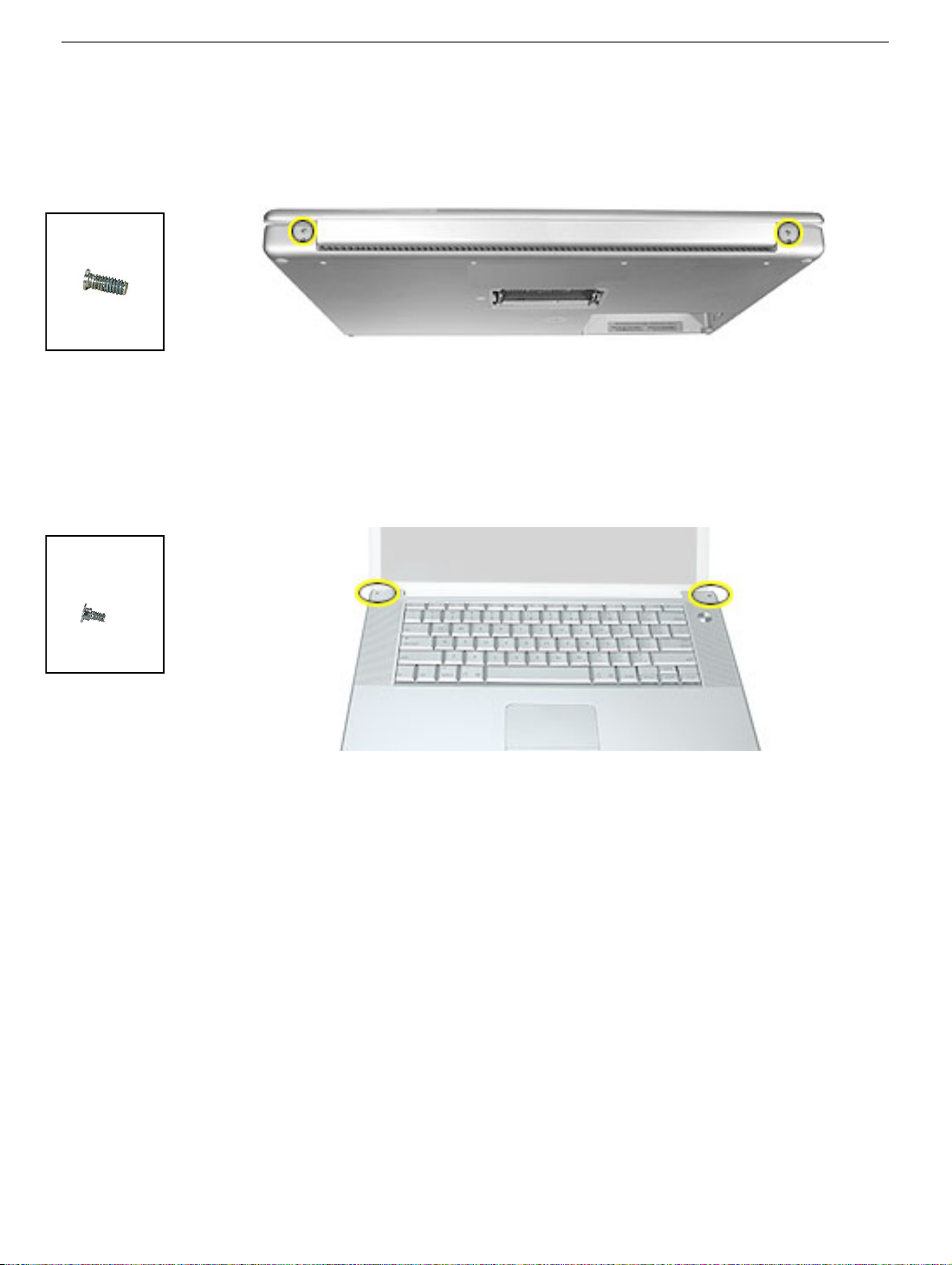
7. Open the computer slightly and rest it with the back facing up. Remove the two top
screws along the back.
Note:
Do not remove the bottom screws.
8. Lay the computer right side up and open the display slightly past 90-degrees.
9. Remove the two hex screws at the back corners of the top case (a Torx T6 can also be
used).
4.4 mm
16 -
PowerBook G4 (15-inch Double-Layer SD) Take Apart
Top Case
Page 27
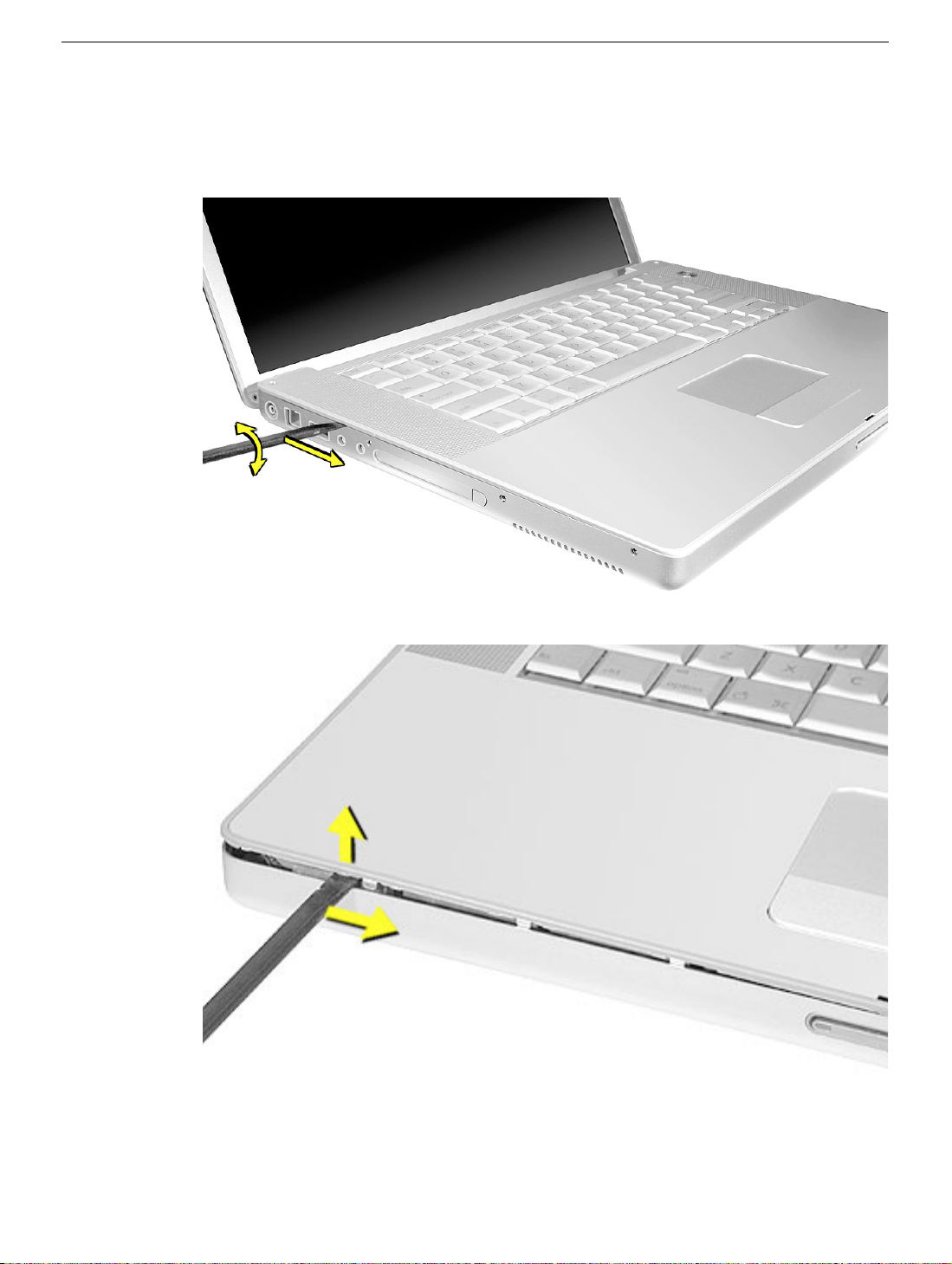
10. Along the left side, near the back, insert a black stick into the space between the top
and bottom case. Work the black stick forward with a twisting motion until the black
stick can be inserted on the left side of the front.
Top Case
PowerBook G4 (15-inch Double-Layer SD) Take Apart -
17
Page 28
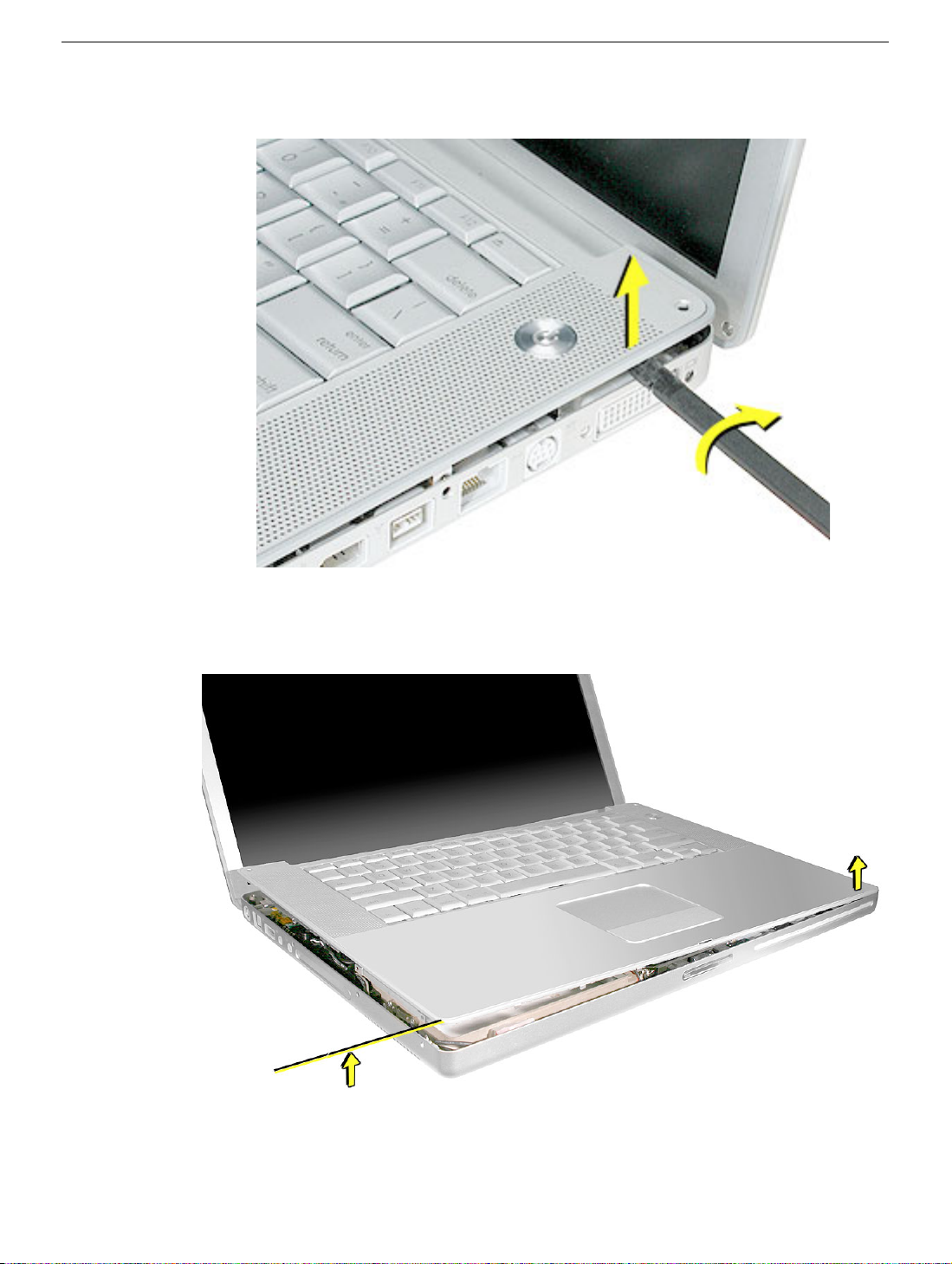
11. Loosen the back right side, if needed.
12. Work the left side up until the four catches over the optical drive slot release along the
right side, then lift the top case straight up, slightly, to release it completely, but do not
remove.
18 -
PowerBook G4 (15-inch Double-Layer SD) Take Apart
Top Case
Page 29
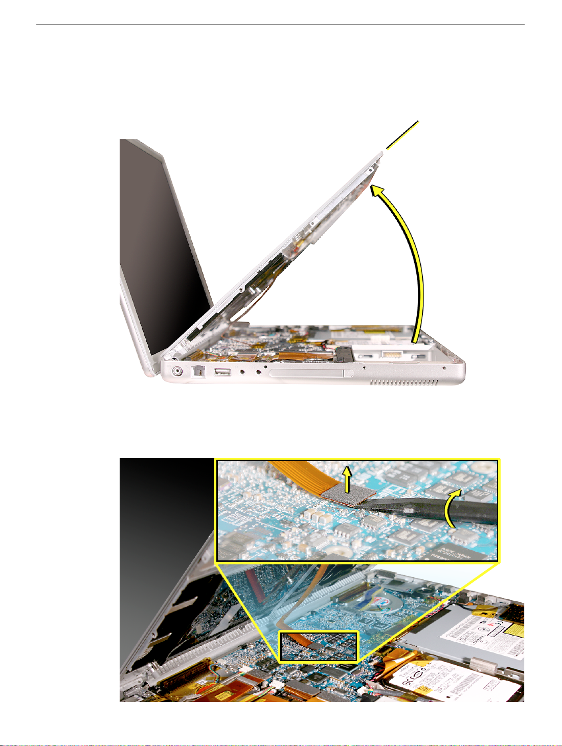
13. Lift the front of the top case and pivot along the back edge to about 45-degrees, to
expose the keyboard flex cable connected to the logic board.
Important:
Do not lift off the top case or strain the keyboard flex cable.
14. Remove any Kapton tape from the keyboard connector on the logic board, then use a
black stick to disconnect the flex cable. Lift off the top case.
Replacement Note:
When reinstalling, reapply Kapton tape where it was removed.
Top Case
PowerBook G4 (15-inch Double-Layer SD) Take Apart -
19
Page 30
Replacement Procedure
Note: If replacing the top case, remove the keyboard and transfer to the replacement top case.
1. Visually check to verify that all cables are connected and routed correctly with nothing
raised up or incorrectly over a component.
2. Check perimeter wiring and cables around clutches to verify that they will not be
caught or pinched by the top case during replacement.
3. Verify that the LVDS cable is secure and lays flat.
4. On the top case, check cable connections and routing.
20 -
PowerBook G4 (15-inch Double-Layer SD) Take Apart
Top Case
Page 31

5. Check that the perimeter metal tabs are not bent.
Note: The metal quickly fatigues and can break off easily. Be extremely careful to
gently straighten tabs, if needed.
6. Connect the flex cable from the top case to the logic board.
7. Lift the top case slightly and rotate it down over the bottom case (verify that the cable
is folding properly) and align the corners.
8. Start at the right corner and guide the top case onto the bottom case. Use a black
stick to carefully pull or push tabs slightly, if needed.
Top Case
PowerBook G4 (15-inch Double-Layer SD) Take Apart - 21
Page 32

922-6091
3.4 mm
Important Notes:
• Some side screws have a flexible screw boss. If they block a tab on the top case from
seating, use the pointed end of a black stick through the screw hole to push on the
boss slightly.
• The tabs are fragile. Do not apply too much pressure or bend them.
• The top case should lay flat along the sides and top, if not, make sure that cables and
components are not interfering.
• Screw order is vital for the proper attachment of the top case.
9. Reinstall the side screws in the order shown, below.
Replacement Note: Do NOT insert side screws into the DVI port screw holes. The
screws can jam in the holes, requiring removing the logic board to remove.
922-6091
3.4 mm
22 - PowerBook G4 (15-inch Double-Layer SD) Take Apart
Top Case
Page 33

922-6095
16.4 mm
922-6719
12.6 mm
922-6091
10. Close the computer, flip it over, and install the four back screws.
11. Install the two screws in the memory bay.
12. Install the memory door and four screws.
13. Install the two screw in the battery bay.
3.4 mm
14. Replace the battery.
15. Testing the computer should include powering on, checking the keyboard and
trackpad function.
Operate the computer in a darkened room to check for keyboard backlight function.
Top Case
PowerBook G4 (15-inch Double-Layer SD) Take Apart - 23
Page 34

Keyboard
Tools
This procedure requires the following tools:
• #0 Phillips screwdriver
• Black stick (or other nonconductive nylon or plastic flat-blade tool)
• Kapton tape
Part Location
Preliminary Steps
Before you begin, remove the following:
• Battery
• Top case
24 - PowerBook G4 (15-inch Double-Layer SD) Take Apart
Keyboard
Page 35

Procedure
Keyboard for the PowerBook G4 (15-inch Double-Layer SD) and (15-inch 1.67/1.5GHz)
computers have different construction, and removal and installation procedures than
previous models.
Important Notes:
• The PowerBook G4 (15-inch Double-Layer SD) keyboards are not interchangeable
with previous models. Verify that the correct replacement keyboard is ordered, and/or
top case if replacing.
• The keyboard comes as a multi-layered assembly, and all include backlighting. Do not
disassemble the keyboard assembly. Dust, fingerprints, or misalignment, can cause
improper function and damage.
1. On a clean flat surface, turn the top case upside down, with the keyboard side nearer
to you.
2. Locate the keyboard flex cable connectors. Also, note the location and remove any
Kapton tape.
Replacement Note: Kapton tape must be installed in the same manner during
reassembly.
Keyboard
PowerBook G4 (15-inch Double-Layer SD) Take Apart - 25
Page 36

3. Very carefully lift the front of the two connectors to release the keyboard flex cables,
as shown.
Important: The connectors are delicate. If damaged, the top case must be replaced.
Replacement Note: Verify that the cables are fully inserted and secured straight.
4. Note the position, then carefully peel off the insulator film covering the back of the
keyboard well. Reserve the film and keep it clean for reinstallation.
Note: The film may be a different color and design than shown here.
26 - PowerBook G4 (15-inch Double-Layer SD) Take Apart
Keyboard
Page 37

5. Use needlenose pliers to straighten the four bend-tabs located along the bottom edge,
as shown. These tabs lock down and stiffen the top edge of the keyboard.
Important: The bend-tabs are delicate. Bend them carefully to avoid damage. Avoid
overbending.
922-6718
1.6 mm
6. Remove the ten keyboard screws.
Keyboard
PowerBook G4 (15-inch Double-Layer SD) Take Apart - 27
Page 38

7. Note the six insert-tabs along the middle edge, and two on each side. The following
procedures release these tabs so that the keyboard can be removed.
8. To prevent the keyboard from falling out, support it with your hand, and raise the top
case up vertically.
Note: The keyboard does not have adhesive under it, as in previous models.
28 - PowerBook G4 (15-inch Double-Layer SD) Take Apart
Keyboard
Page 39

9. If needed, push through one of the top center keyboard screw holes, with the point of
a black stick, to bow out the keyboard slightly.
Important: Ensure that the hole used is a screw hole, or damage to other sensitive
components may result. A black stick is used to avoid damaging the screw boss
threads—do not use a metal tool.
10. Important: During this procedure, do not allow the tabs or metal edge of the keyboard
to scrape along the cosmetic surface of the top case, or damage can result.
Keyboard
PowerBook G4 (15-inch Double-Layer SD) Take Apart - 29
Page 40

11. Use your finger to hold the bowed out keyboard. Continue to bow it out only enough
for the tabs on one side of the keyboard to release cleanly. Repeat for the other side.
Important: Do not bow the keyboard too much, or it may become permanently bent.
30 - PowerBook G4 (15-inch Double-Layer SD) Take Apart
Keyboard
Page 41

12. Lift the keyboard up to release the tabs along the bottom edge and carefully thread out
the flex cables.
Keyboard
PowerBook G4 (15-inch Double-Layer SD) Take Apart - 31
Page 42

Replacement Procedure
When replacing the keyboard, here are some key points to ensure:
• Prevention of scratches to the cosmetics of the top case
• All tabs are properly seated
• Keyboard lays flat
• Cables not caught
• Bend-tabs are not damaged
• Screw holes align
• Cable connectors are not damaged and cables secure properly
• Kapton tape is applied as before
• Insulator film is correctly installed
1. Before replacing or installing a replacement keyboard, verify that the four bend-tabs
along the bottom edge of the keyboard, are straight and parallel with the bottom edge.
Important: Do not bend any other bend-tabs on the keyboard other than the four
along the bottom. Other tabs hold the keyboard assembly together.
32 - PowerBook G4 (15-inch Double-Layer SD) Take Apart
Keyboard
Page 43

2. Guide the keyboard’s flex cables through the slot in the top case, as shown. Make sure
that they do not catch or bend behind the keyboard.
3. Lower the keyboard and seat all six tabs along the bottom, so that the keyboard sits
flat and straight.
Keyboard
PowerBook G4 (15-inch Double-Layer SD) Take Apart - 33
Page 44

Important: During the next steps, do not allow the tabs or metal edge of the keyboard to
scrape along the cosmetic surface of the top case, or damage can result.
4. While ensuring that the keyboard bottom stays straight and secure, hold the top of the
keyboard in the middle, then with your other hand, bow in one side of the keyboard to
engage the two tabs at the top into the top case.
Important: Do not bow the keyboard too much, or it may become permanently bent.
34 - PowerBook G4 (15-inch Double-Layer SD) Take Apart
Keyboard
Page 45

5. Use the heel of your hand to hold in place the edge of the keyboard that was just
inserted while holding the top of the keyboard with a finger on that hand, then use your
other hand to help bow in the remaining side of the keyboard until it can be engaged.
Keyboard
PowerBook G4 (15-inch Double-Layer SD) Take Apart - 35
Page 46

6. While supporting the keyboard in the top case, verify that the keyboard lays flat and
that all the tabs have seated properly.
Note: The keyboard will not sit flat if any of the tabs have not seated properly. If the
side tabs are not seating or are binding, check the bottom edge of the keyboard to
verify that all the tabs are seated and the bottom of the keyboard is straight.
7. Verify that the bend-tabs are not caught.
8. Lay the top case flat, and upside down.
9. Pull on the flex cables to verify that they are not bent or caught under the keyboard,
and that they extend to their connectors.
10. Verify that the screw holes align with the screw bosses and install all ten keyboard
screws, starting from the middle and work out.
11. Bend the four bend-tabs over the metal of the bottom case to secure the bottom edge
of the keyboard.
Important: The bend-tabs are delicate. Bend them carefully to avoid damage and no
more than 90-degrees, or to, or within, any etch marks, if present. Avoid over
bending.
36 - PowerBook G4 (15-inch Double-Layer SD) Take Apart
Keyboard
Page 47

12. Insert the flex cables into their connectors and secure. Install Kapton tape in the same
location as it was removed.
13. Replace the insulator film in the same locations as they were removed. Ensure the
holes in the film match up correctly with the screw bosses. Avoid wrinkles and bulges.
If installing a replacement top case, use the new film if supplied.
Important: The film must be installed and in the same location to protect against
contact and electrical shorting in certain areas and to allow contact with the EMI
spring on the logic board.
14. If the film extends over the edge of the keyboard well, run your finger along the edges
to secure it to the top case.
Note: Picture for illustration only. The insulator film may be different.
Keyboard
15. Reassemble the computer.
16. Testing the computer should include powering on, checking the keyboard and
trackpad function.
Operate the computer in a darkened room to check for keyboard backlight function,
and light leakage around the perimeter of the keyboard, speaker grill openings and
side ports.
PowerBook G4 (15-inch Double-Layer SD) Take Apart - 37
Page 48

Backup Battery
Tools
This procedure requires the following tools:
• Black stick (or other nonconductive nylon or plastic flat-blade tool)
Part Location
Preliminary Steps
Before you begin, remove the following:
• Battery
• Top case
38 - PowerBook G4 (15-inch Double-Layer SD) Take Apart
Backup Battery
Page 49

Procedure
Note: Previous model battery shown.
1. Use a black stick to release the adhesive holding the backup battery to the optical
drive then disconnect the backup battery cable.
Note: The backup battery is held down by double-backed tape adhesive on its cover.
Backup Battery
PowerBook G4 (15-inch Double-Layer SD) Take Apart - 39
Page 50

Replacement Procedure
1. Connect the backup battery cable to the backup battery and to the logic board.
2. Remove any protective adhesive cover on the replacement backup battery.
3. Position the backup battery precisely to the dimensions shown below.
Note: Measurements are from the edge of the optical drive and the optical drive
bracket to the backup battery board and the battery (not the protective cover).
Important: If the backup battery is not positioned correctly, sharp edges on the top
case, and on the optical drive bracket, may cause damage.
40 - PowerBook G4 (15-inch Double-Layer SD) Take Apart
Backup Battery
Page 51

4. Press where shown to secure the backup battery to the optical drive.
5. Reassemble the computer.
6. Testing the computer should include plugging in the power adapter and letting the
backup battery charge for half an hour. Then power on the computer and disconnect
the power adapter, set the system clock, put the computer to sleep, remove the main
battery for five seconds and reinstall. The date and time should not reset.
Also, insert an optical disc to verify that the optical drive functions properly.
Backup Battery
PowerBook G4 (15-inch Double-Layer SD) Take Apart - 41
Page 52

Battery Connector
Tools
This procedure requires the following tools:
• #0 Phillips screwdriver (magnetized)
• Black stick (or other nonconductive nylon or plastic flat-blade tool)
Part Location
Preliminary Steps
Before you begin, remove the following:
• Battery
• Top case
42 - PowerBook G4 (15-inch Double-Layer SD) Take Apart
Battery Connector
Page 53

922-6092
3.5 mm
922-6472
4.5 mm
Procedure
1. Remove three screws.
2. Install the battery connector and ground screw lead.
Note: Do not overtighten the two main battery connector screws. There will be play in
the battery connector when the screws are secured.
3. Connect the main cable to its connector on the underside of the logic board.
4. Reassemble the computer.
5. Testing should include plugging in the power adapter and battery charging, then
running the computer from battery power. Verify that the sleep LED functions properly.
Battery Connector
PowerBook G4 (15-inch Double-Layer SD) Take Apart - 43
Page 54

Left Blower
Tools
This procedure requires the following tools:
• #0 Phillips screwdriver (magnetized)
• Black stick (or other nonconductive nylon or plastic flat-blade tool)
Part Location
Preliminary Steps
Before you begin, remove the following:
• Battery
• Top case
Note: Replacing the right blower requires removing the logic board.
44 - PowerBook G4 (15-inch Double-Layer SD) Take Apart
Left Blower
Page 55

Procedure
1. Disconnect the four cables shown below.
922-6093
4.5 mm
2. Remove four screws.
Left Blower
PowerBook G4 (15-inch Double-Layer SD) Take Apart - 45
Page 56

3. Carefully separate any tape used to seal the back edge as you lift out the blower.
4. Install replacement blower. Use Kapton tape to seal as necessary.
5. Use Kapton tape to ensure that the cables lay flat, and that wires will not move into the
PC card cage.
6. Reassemble and test computer.
Replacement Note: Ensure that Kapton tape is installed over the fins of the blower.
46 - PowerBook G4 (15-inch Double-Layer SD) Take Apart
Left Blower
Page 57

Optical Drive
Tools
This procedure requires the following tools:
• #0 Phillips screwdriver (magnetized)
• Thin double-back tape (if the backup battery will not re-stick securely)
• Black stick (or other nonconductive nylon or plastic flat-blade tool)
Part Location
Optical Drive
Preliminary Steps
Before you begin, remove the following:
• Battery
• Top case
• Backup battery
PowerBook G4 (15-inch Double-Layer SD) Take Apart - 47
Page 58

922-6097
6.4 mm
Procedure
1. Remove the three screws from the drive holder.
2. Lift out the bracket.
Replacement Note: Verify that the EMI gasket is securely in place.
48 - PowerBook G4 (15-inch Double-Layer SD) Take Apart
Optical Drive
Page 59

922-6090
3.2 mm
3. Use a black stick to carefully disconnect the optical drive flex cable connector.
4. Remove the screw, shown.
5. Lift up at the rear of the drive and remove.
Warning: Hold the optical drive at its side edges. Do not put pressure in the middle.
Optical Drive
PowerBook G4 (15-inch Double-Layer SD) Take Apart - 49
Page 60

922-6488
2.15 mm
6. Transfer the flex cable, side brackets and screws to the replacement optical drive.
7. Transfer the cosmetic cover to the replacement optical drive.
50 - PowerBook G4 (15-inch Double-Layer SD) Take Apart
Optical Drive
Page 61

8. To install the replacement optical drive, insert the front of the drive and ensure that the
holes in the front brackets fit over the pins on the internal frame, while lowering the
back of the drive into place.
Optical Drive
9. Verify that both sides of the drive are fully seated, and reinstall the screw.
10. Connect the optical drive flex cable connector to the logic board.
11. Reassemble the computer.
12. Testing the computer should include powering on, inserting an optical disc and
ejecting it to make sure the drive is aligned with the opening and functioning properly.
Test the backup battery by plugging in the power adapter and letting the backup
battery charge for half an hour. Then power on the computer and disconnect the
power adapter, set the system clock, put the computer to sleep, remove the main
battery for five seconds and reinstall. The date and time should not reset.
PowerBook G4 (15-inch Double-Layer SD) Take Apart - 51
Page 62

How to remove a stuck disc from an MKE optical drive
Important: These procedures apply to MKE optical drives, only.
1. Remove the four identical screws that hold the top cover to the drive.
2. Slide the top cover approximately 2 mm toward the back of the drive. Lift up the top
cover to remove it.
52 - PowerBook G4 (15-inch Double-Layer SD) Take Apart
Optical Drive
Page 63

3. Check the placement of the disc. It is either clamped to the turntable at the center of
the disc, or it is wedged under one or more posts at the outer edge of the disc.
4. Holding the edge of the disc, press on the center clamp or hold the posts steady as
you remove the disc from the drive.
Important: Do not touch any key components located near the disc.
5. Replace the top cover on the drive so that the small hooks on the top cover fit into the
slots on the bottom cover. Then slide the top cover into place.
6. Replace the four screws.
7. Install the replacement drive, and reassemble and test the computer.
Optical Drive
PowerBook G4 (15-inch Double-Layer SD) Take Apart - 53
Page 64

Hard Drive
Tools
This procedure requires the following tools:
• #0 Phillips screwdriver (magnetized)
• Black stick (or other nonconductive nylon or plastic flat-blade tool)
Part Location
Preliminary Steps
Before you begin, remove the following:
• Battery
• Top case
54 - PowerBook G4 (15-inch Double-Layer SD) Take Apart
Hard Drive
Page 65

922-6097
6.4 mm
Procedure
1. Remove the three screws from the drive holder.
2. Lift out the bracket.
Hard Drive
PowerBook G4 (15-inch Double-Layer SD) Take Apart - 55
Page 66

3. Use a black stick to carefully disconnect the hard drive flex cable connector.
4. Lift up on the right side of the hard drive to remove.
56 - PowerBook G4 (15-inch Double-Layer SD) Take Apart
Hard Drive
Page 67

922-6083
5.8 mm
5. Transfer the shield, side screws, rubber shockpads and the flex cable to the
replacement hard drive.
6. Install the replacement hard drive and reassemble the computer.
7. When installing the replacement drive... to avoid exposing the hard drive flex cable
contacts, as shown here,...
Hard Drive
PowerBook G4 (15-inch Double-Layer SD) Take Apart - 57
Page 68

use a black stick to guide the foam (covering the contacts) past the logic board,
while...
guiding the rubber shockpads securely into the holes in the hard drive holder.
58 - PowerBook G4 (15-inch Double-Layer SD) Take Apart
Hard Drive
Page 69

8. Make sure all shockpads are seated correctly.
9. When replacing the hard drive/optical drive holder, make sure that the Mylar shield is
not caught.
10. Testing the computer should include powering on, keyboard and trackpad function,
verify that the hard drive is recognized, and that the speakers, and modem works.
Hard Drive
PowerBook G4 (15-inch Double-Layer SD) Take Apart - 59
Page 70

Sleep LED
Tools
This procedure requires the following tools:
• #0 Phillips screwdriver (magnetized)
• Black stick (or other nonconductive nylon or plastic flat-blade tool)
Part Location
Preliminary Steps
Before you begin, remove the following:
• Battery
• Top case
• Hard drive
60 - PowerBook G4 (15-inch Double-Layer SD) Take Apart
Sleep LED
Page 71

922-6093
4.5 mm
Procedure
1. Remove the screw.
2. Follow the Sleep LED board wire to its connector on the logic board and disconnect it.
Lift up any Kapton tape to release the cable, and replace during reinstallation.
Sleep LED
3. Testing the computer should include sleep LED function, hard drive, keyboard and
trackpad.
PowerBook G4 (15-inch Double-Layer SD) Take Apart - 61
Page 72

Right Speaker
Tools
This procedure requires the following tools:
• #1 Phillips screwdriver (magnetized)
• Black stick (or other nonconductive nylon or plastic flat-blade tool)
Part Location
Preliminary Steps
Before you begin, remove the following:
• Battery
• Top case
62 - PowerBook G4 (15-inch Double-Layer SD) Take Apart
Right Speaker
Page 73

922-6475
9.5 mm
Procedure
1. Remove one screw.
2. Use a black stick to carefully pry out the speaker, as shown.
Note: The right speaker is an assembly that contains the right ambient light sensor
lens. Do not disassemble.
Right Speaker
PowerBook G4 (15-inch Double-Layer SD) Take Apart - 63
Page 74

3. Follow the speaker’s wire to the main speaker cable connector and disconnect it.
Note: Lift Kapton tape as needed and note the wire routing for reinstallation. Replace
Kapton tape when reinstalling.
4. To install the right speaker, line up the screw hole in the ALS lens with the hole in the
logic board, then press on the hard plastic that surrounds the flexible speaker, to fully
seat it into the speaker chamber beneath the logic board.
Important: Do not press on the flexible part of the speaker.
64 - PowerBook G4 (15-inch Double-Layer SD) Take Apart
Right Speaker
Page 75

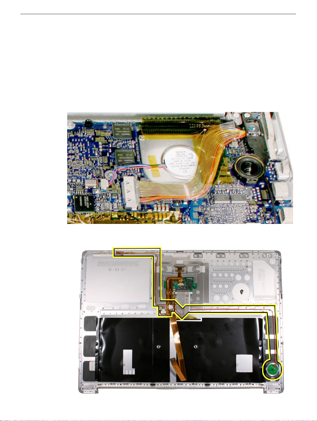
5. Route the speaker cable under flex cables and along the path shown below. Secure in
place with Kapton tape as needed.
6. Reassemble the computer and test the speakers, including using the Sound system-
preference pane.
Right Speaker
PowerBook G4 (15-inch Double-Layer SD) Take Apart - 65
Page 76

Left Ambient Light Sensor (ALS)
Important:
• The left ALS cable connects to the logic board in the same connector type and same
general location as the inverter cable. Make sure to connect to the correct connector.
Tools
This procedure requires the following tools:
• #0 Phillips screwdriver (magnetized)
• Black stick (or other nonconductive nylon or plastic flat-blade tool)
Part Location
Preliminary Steps
Before you begin, remove the following:
• Battery
• Top case
66 - PowerBook G4 (15-inch Double-Layer SD) Take Apart
Left Ambient Light Sensor (ALS)
Page 77

922-6090
3.2 mm
Procedure
1. Remove the two screws and disconnect the flex cable, shown.
2. Lift the flex cable and disconnect the ALS cable from the logic board.
3. Replacement Note: Verify that the cable is connected to the correct connector on the
logic board, as shown above.
4. Reassemble the computer and test the ambient light sensor operation, trackpad, and
keyboard.
Left Ambient Light Sensor (ALS)
PowerBook G4 (15-inch Double-Layer SD) Take Apart - 67
Page 78

Left Speaker
Tools
This procedure requires the following tools:
• 4mm Hex socket wrench
• Black stick (or other nonconductive nylon or plastic flat-blade tool)
Part Location
Preliminary Steps
Before you begin, remove the following:
• Battery
• Top case
• Left ambient light sensor
68 - PowerBook G4 (15-inch Double-Layer SD) Take Apart
Left Speaker
Page 79

922-5840
4 mm
Procedure
1. Remove the hex nut.
2. Lift the speaker slightly to reveal the speaker wire connector and disconnect.
Left Speaker
3. Reassemble the computer and test the speakers, including using the Sound system-
preference pane.
PowerBook G4 (15-inch Double-Layer SD) Take Apart - 69
Page 80

PC Card Cage
Tools
This procedure requires the following tools:
• #0 Phillips screwdriver (magnetized)
• Black stick (or other nonconductive nylon or plastic flat-blade tool)
Part Location
Preliminary Steps
Before you begin, remove the following:
• Battery
• Top case
• Left ambient light sensor board
• Left speaker
70 - PowerBook G4 (15-inch Double-Layer SD) Take Apart
PC Card Cage
Page 81

Procedure
1. Use a black stick to disconnect the PC card cage flex cable.
922-6093
4.5 mm
922-6470
6.6 mm
2. Remove the four screws.
PC Card Cage
PowerBook G4 (15-inch Double-Layer SD) Take Apart - 71
Page 82

3. Carefully lift up the PC card cage to clear the pin on the eject button.
922-6093
4.5 mm
922-6470
6.6 mm
4. Insert the replacement PC card cage and eject button.
Replacement Note: Ensure that the pin on the PC card cage eject button is secured
by the hole in the cage mechanism, as shown above.
5. Align the holes in the cage with the screw bosses on the bottom case.
6. Lightly install all four screws before tightening (note: longer screws go in the back by
the flex cable), then tighten in the following order.
72 - PowerBook G4 (15-inch Double-Layer SD) Take Apart
PC Card Cage
Page 83

7. Reassemble the computer.
8. Testing should include inserting a PC card to check that it can be locked in and that
the eject button works smoothly. Check that the speakers work, and that the trackpad
and keyboard function properly. Check that the modem and Bluetooth operate.
Operate the computer in a darkened room to check for keyboard backlight function.
PC Card Cage
PowerBook G4 (15-inch Double-Layer SD) Take Apart - 73
Page 84

AirPort Extreme w/ Bluetooth
Tools
This procedure requires the following tools:
• #0 Phillips screwdriver (magnetized)
• Black stick (or other nonconductive nylon or plastic flat-blade tool)
Part Location
Preliminary Steps
Before you begin, remove the following:
• Battery
• Top case
• PC card cage
74 - PowerBook G4 (15-inch Double-Layer SD) Take Apart
AirPort Extreme w/ Bluetooth
Page 85

Procedure
1. Disconnect the flex cable.
2. Carefully lift off the antenna cables.
922-6090
3.2 mm
3. Remove the two screws.
4. Reassemble the computer.
AirPort Extreme w/ Bluetooth
PowerBook G4 (15-inch Double-Layer SD) Take Apart - 75
Page 86

5. Testing the computer should include using Apple System Profiler to check that the
AirPort Extreme card is recognized, test that the AirPort Extreme card is working,
insert a PC card to check that it can be locked in and that the eject button works
smoothly. Check that both speakers work, and that the trackpad and keyboard
function properly. Check that the modem and Bluetooth operate. Operate the
computer in a darkened room to check for keyboard backlight function.
76 - PowerBook G4 (15-inch Double-Layer SD) Take Apart
AirPort Extreme w/ Bluetooth
Page 87

Modem
Important:
• The flex cable routes under the logic board and is secured by adhesive foam. The
logic board must be removed to remove or replace the modem flex cable.
• There are two insulator washers, one on each side of the modem, on the modem
screw nearest the logic board.
• A grounding strap on the speaker cable must be captured by the modem screw.
Tools
This procedure requires the following tools:
• #0 Phillips screwdriver (magnetized)
• Black stick (or other nonconductive nylon or plastic flat-blade tool)
Part Location
Modem
PowerBook G4 (15-inch Double-Layer SD) Take Apart - 77
Page 88

Preliminary Steps
Before you begin, remove the following:
• Battery
• Top case
• PC card cage
Procedure
1. Disconnect the flex. Important: Do not attempt to disconnect it from the logic board.
2. Remove the two screws.
Replacement Note: One screw secures a metallic strap attached to the main
speaker cable.
78 - PowerBook G4 (15-inch Double-Layer SD) Take Apart
Modem
Page 89

Important: The screw nearest the logic board uses two insulator washers. One on
the screw (922-7145) and one on the internal frame under the modem. Make sure
that these insulators are in place before reinstalling the modem.
3. Disconnect the modem RJ-11 cable from the end of the modem.
Modem
4. Install the modem, reassemble the computer and test the modem.
PowerBook G4 (15-inch Double-Layer SD) Take Apart - 79
Page 90

Sound/DC-In Board
Tools
This procedure requires the following tools:
• #1 Phillips screwdriver (magnetized)
• 5 mm socket wrench
• Black stick (or other nonconductive nylon or plastic flat-blade tool)
Part Location
Preliminary Steps
Before you begin, remove the following:
• Battery
• Top case
• PC card cage
80 - PowerBook G4 (15-inch Double-Layer SD) Take Apart
Sound/DC-In Board
Page 91

922-7146
14.2 mm
922-6472
4.5 mm
Procedure
1. Disconnect the flex connector, speaker wire, power cable, and remove the screw and
hexnut screw.
2. Move the board clear of the bottom case port openings, then rotate up.
Sound/DC-In Board
PowerBook G4 (15-inch Double-Layer SD) Take Apart - 81
Page 92

3. Guide out the DC-in port.
4. Guide out the DC-in port.
82 - PowerBook G4 (15-inch Double-Layer SD) Take Apart
Sound/DC-In Board
Page 93

5. Disconnect the power cable.
6. Slide out the RJ-11 port with cable and transfer it to the replacement board.
Note: Pull on the port, or push it with the flat blade of a black stick, until it begins to
move, then use the black stick to create leverage behind the port.
Sound/DC-In Board
PowerBook G4 (15-inch Double-Layer SD) Take Apart - 83
Page 94

7. Verify that the rubber block is on the replacement board, or transfer from the replaced
board.
Replacement Note: Use care during reassembly that the block is not dislodged.
8. Install the replacement sound/DC-in board.
Replacement Notes:
• Connect the power cable to the sound/DC-in board, and the modem cable to the
modem, before installing.
• Verify that the screw pass-through holes, near the speaker wire connector, line up with
the PC card cage screw bosses below them.
84 - PowerBook G4 (15-inch Double-Layer SD) Take Apart
Sound/DC-In Board
Page 95

• While tightening the screws, push the board toward the port holes in the bottom case
to ensure the DC plug is fully seated into its port.
• Verify that the port EMI metal rests above the port plastic.
• Verify that the EMI gasket is installed (076-1201).
9. Connect the speaker and flex cables.
Note:
• Install the “TO MLB” side of the flex cable to the logic board.
• The flex cable should go under the sound/DC-in board power cable.
Sound/DC-In Board
PowerBook G4 (15-inch Double-Layer SD) Take Apart - 85
Page 96

10. Reassemble and test the computer.
11. Testing should include checking the function of the modem port, DC-in port, the left
USB port, and audio ports.
86 - PowerBook G4 (15-inch Double-Layer SD) Take Apart
Sound/DC-In Board
Page 97

Speaker cable
Tools
This procedure requires the following tools:
• #0 Phillips screwdriver (magnetized)
• Black stick (or other nonconductive nylon or plastic flat-blade tool)
Part Location
Speaker cable
Preliminary Steps
Before you begin, remove the following:
• Battery
• Top case
• Left speaker
• PC card cage
PowerBook G4 (15-inch Double-Layer SD) Take Apart - 87
Page 98

Procedure
1. Disconnect the cable where shown and remove one screw attached to the modem.
2. Install the replacement speaker cable. Make sure to capture the metallic strap with the
modem screw, and route the cable as shown above.
88 - PowerBook G4 (15-inch Double-Layer SD) Take Apart
Speaker cable
Page 99

Logic Board
Tools
This procedure requires the following tools:
• #1 Phillips screwdriver (magnetized)
• Gasket kit (076-1201)
• Black stick (or other nonconductive nylon or plastic flat-blade tool)
• Alcohol pads
• Thermal Grease (922-7144)
Note: Use a tray with divided compartments to organize the screws you remove.
Part Location
Logic Board
PowerBook G4 (15-inch Double-Layer SD) Take Apart - 89
Page 100

Preliminary Steps
Before you begin, run the computer until warm (if possible) to help soften the thermal
material on the logic board, then shut it down and remove the following:
• Battery
• Top case
• PC card cage
• Right speaker
Note: It may be helpful to remove the optical drive and hard drive to reduce the number of
cables to control when replacing the logic board, if desired.
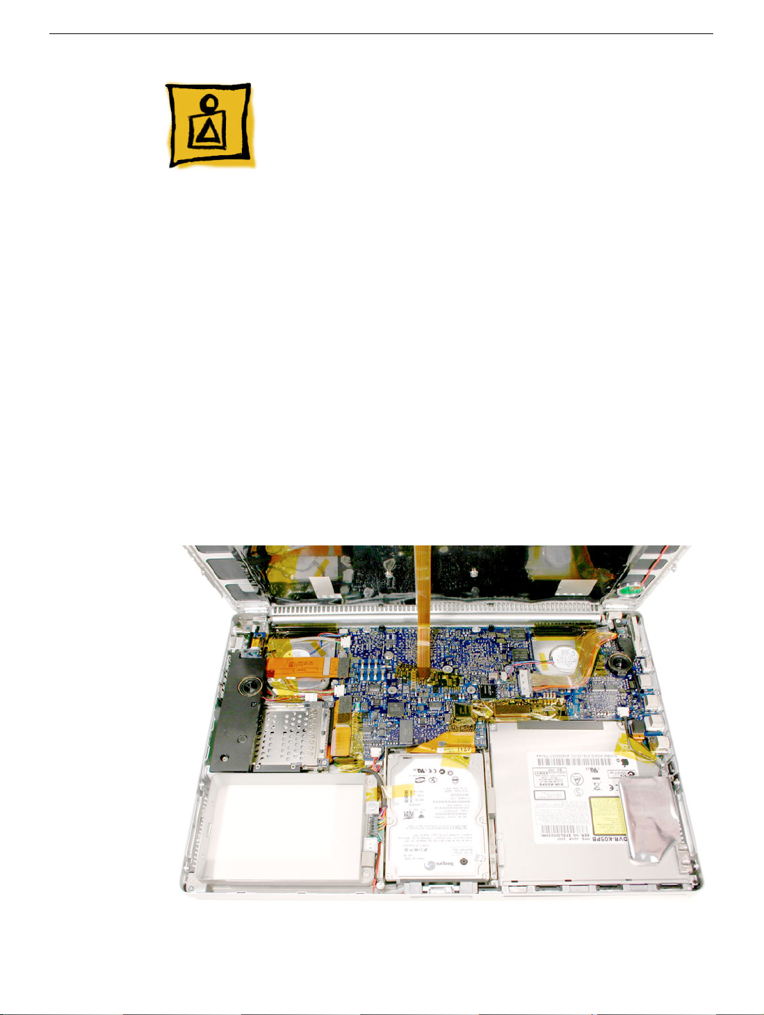
Procedure
1. Disconnect the cables shown.
90 - PowerBook G4 (15-inch Double-Layer SD) Take Apart
Logic Board
 Loading...