


Service Source
PowerBook G4 (12-inch)
PowerBook G4 (12-inch)
PowerBook G4 (12-inch DVI)
Updated October 25, 2005
© 2003 Apple Computer, Inc. All rights reserved.

Service Source
Take Apart
PowerBook G4 (12-inch)
PowerBook G4 (12-inch DVI)
© 2003 Apple Computer, Inc. All rights reserved.
General Information
Overview
Some of the key features that distinguish these computers from earlier notebook models
include:
• 12-inch active-matrix display in aluminum alloy enclosure
• built-in Bluetooth
• slot load optical drive
• optional AirPort Extreme Card and Base Station
General Information
PowerBook G4 (12-inch) Take Apart -
1
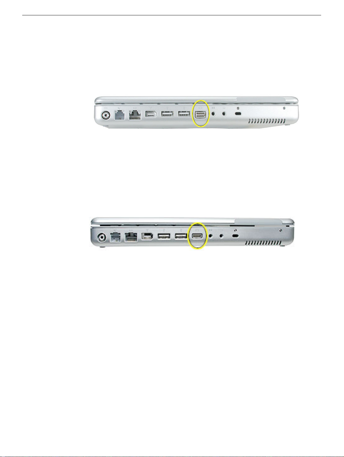
Model Differences
The external housing of the PowerBook G4 (12-inch DVI) model looks the same as the
PowerBook G4 (12-inch) model except for one port. To distinguish the models, look for a
mini-DVI port (shown below) on the PowerBook G4 (12-inch DVI) computer.
PowerBook G4 (12-inch DVI)
The mini-DVI port is used with an adapter cable to connect the computer to a monitor,
television, VCR, or other video device. The adapter cables that can be used with this port
include a mini-DVI-to-DVI adapter, a mini-DVI-to-VGA adapter, and a mini-DVI-to-S-Video
adapter.
By contrast, the PowerBook G4 (12-inch) computer has a video-out VGA port instead of a
mini-DVI port.
PowerBook G4 (12-inch)
Specific model differences that are noted in the Take Apart procedures include
• Reed Switch Board and Cable—For the
PowerBook G4 (12-inch DVI) model, this
part is called the "Hall Effect Sensor Board and Cable," but the procedure is
the same.
• DC-to-DC Board—The
component layout on the board differs, but the procedure
is the same.
• Heatsink—The heatsink shape and thermal pad placement differs.
• Inner Frame—The main frame shape differs, but the procedure is similar.
• RJ11 Modem Board—The procedure is the same, but the placement of the tape that
secures the cable differs.
• Fan—The fan is secured to the heatsink in the
PowerBook G4 (12-inch) model,
but it is secured to the inner frame in the PowerBook G4 (12-inch DVI)
model.
• Logic Board—The component layout on the board differs, but the procedure is the
same.
• Optical Drive—The slot load bezel must be transferred to a replacement optical drive
for the
PowerBook G4 (12-inch) model only.
Important:
to both models.
2 -
PowerBook G4 (12-inch) Take Apart
Unless other specific differences are noted, procedures in this chapter apply
General Information

Tools
Most of the tools required for taking apart these computers are the same as for earlier
notebook models; however, there are three new tools:
• 1.5 mm hex driver (small hex head screwdriver) for the top case and display housing
• 14 mm socket wrench or needlenose pliers for the DC-to-DC board
• tweezers or needlenose pliers (for replacing a foot or for routing thin cables such as
the AirPort antenna cable)
The following tools are recommended for these computers:
• Coin
• ESD wriststrap and mat
• Small soft cloth
• Black stick (or other nonconductive nylon or plastic flat-blade tool)
• #0 Phillips screwdriver (magnetized)
• #1 Phillips screwdriver (magnetized)
• Jeweler’s flat-blade screwdriver
• 1.5 mm hex driver
• 14 mm socket wrench or needlenose pliers
Important:
compartments (such as a plastic ice cube tray). If doing a complete disassembly, note the
screws removed from each location in the computer.
Warning: Check the screw lengths before installing the screws. Installing a longer
screw in the wrong place can permanently damage the housing or an internal part.
To organize the screws you remove from the computer, use a tray with divided
Pictures in this Chapter
Because in some cases the computer was photographed at a pre-release stage, some of
the images pictured in this chapter show boards that are red, rather than green. However,
production models include green boards.
General Information
PowerBook G4 (12-inch) Take Apart -
3
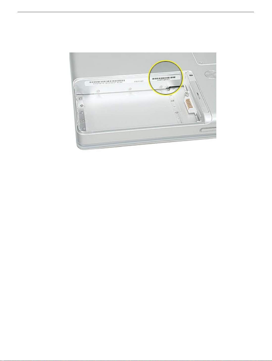
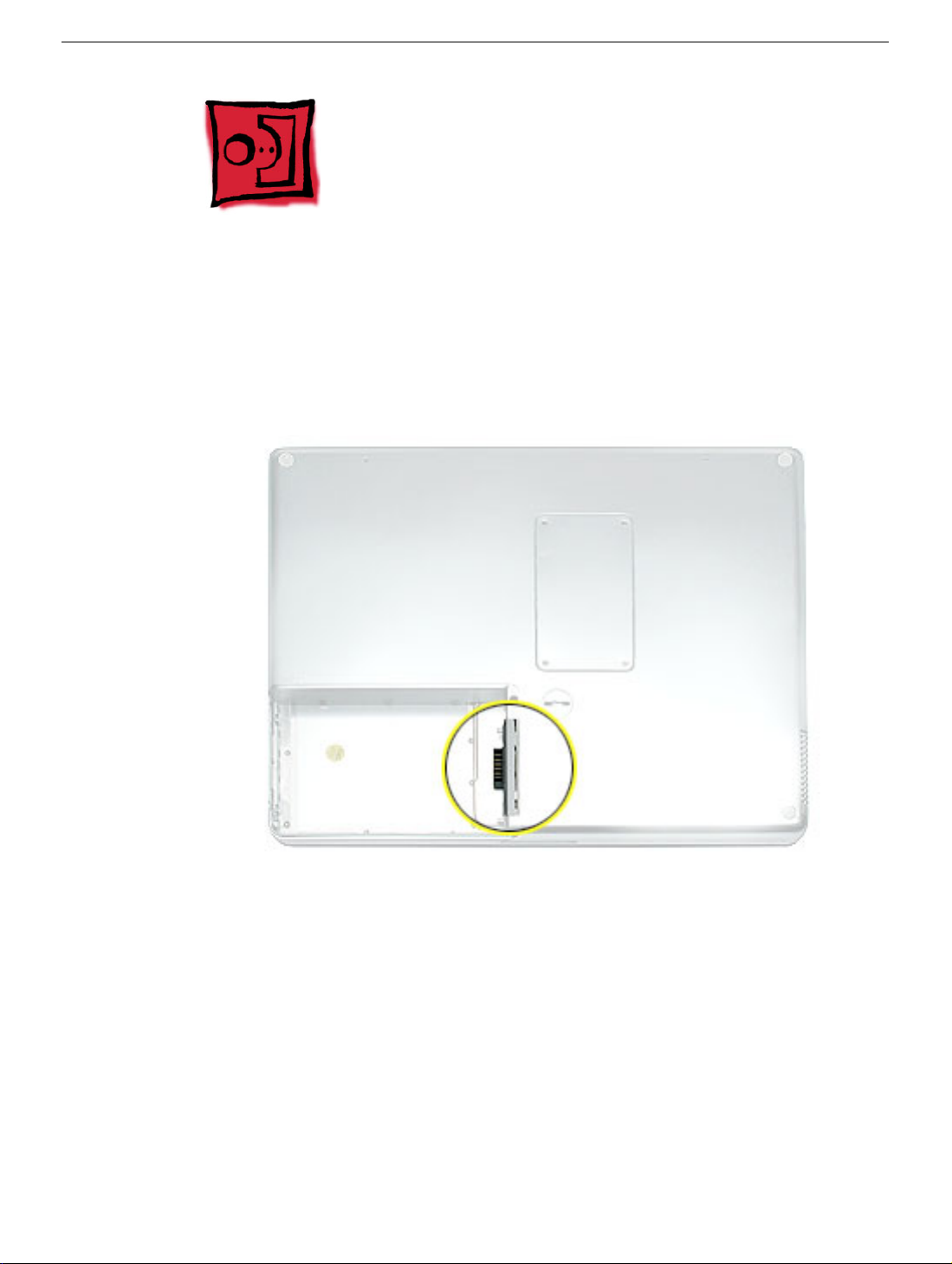
Serial Number Location
The serial number is located in the battery bay.
4 -
PowerBook G4 (12-inch) Take Apart
General Information
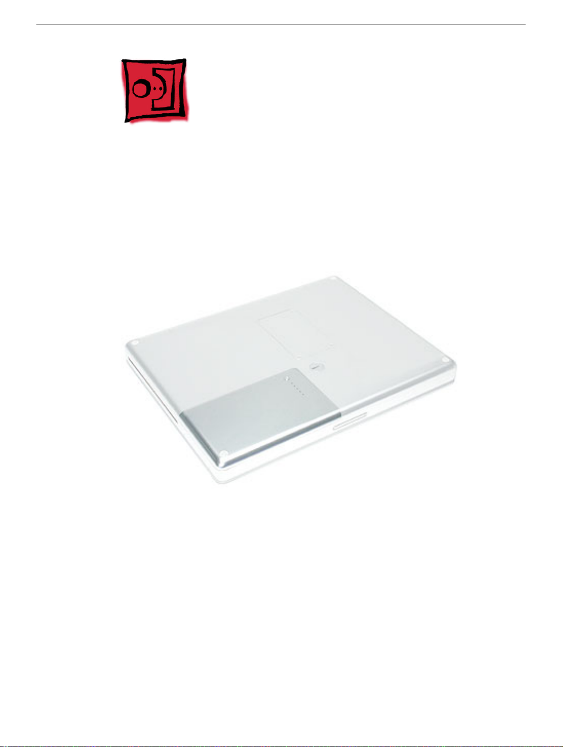
Battery
Tools
This procedure requires the following tools:
• Soft cloth
• Coin
Part Location
Battery
Preliminary Steps
Warning: Always shut down the computer before opening it to avoid damaging its
internal components or causing injury. After you shut down the computer, the
internal components can be very hot. Let the computer cool down for 30 minutes
before continuing.
PowerBook G4 (12-inch) Take Apart -
5
Procedure
Warning:
performing this procedure.
1. Shut down the computer.
2. Unplug the power adapter, phone cord, and any other cables connected to the
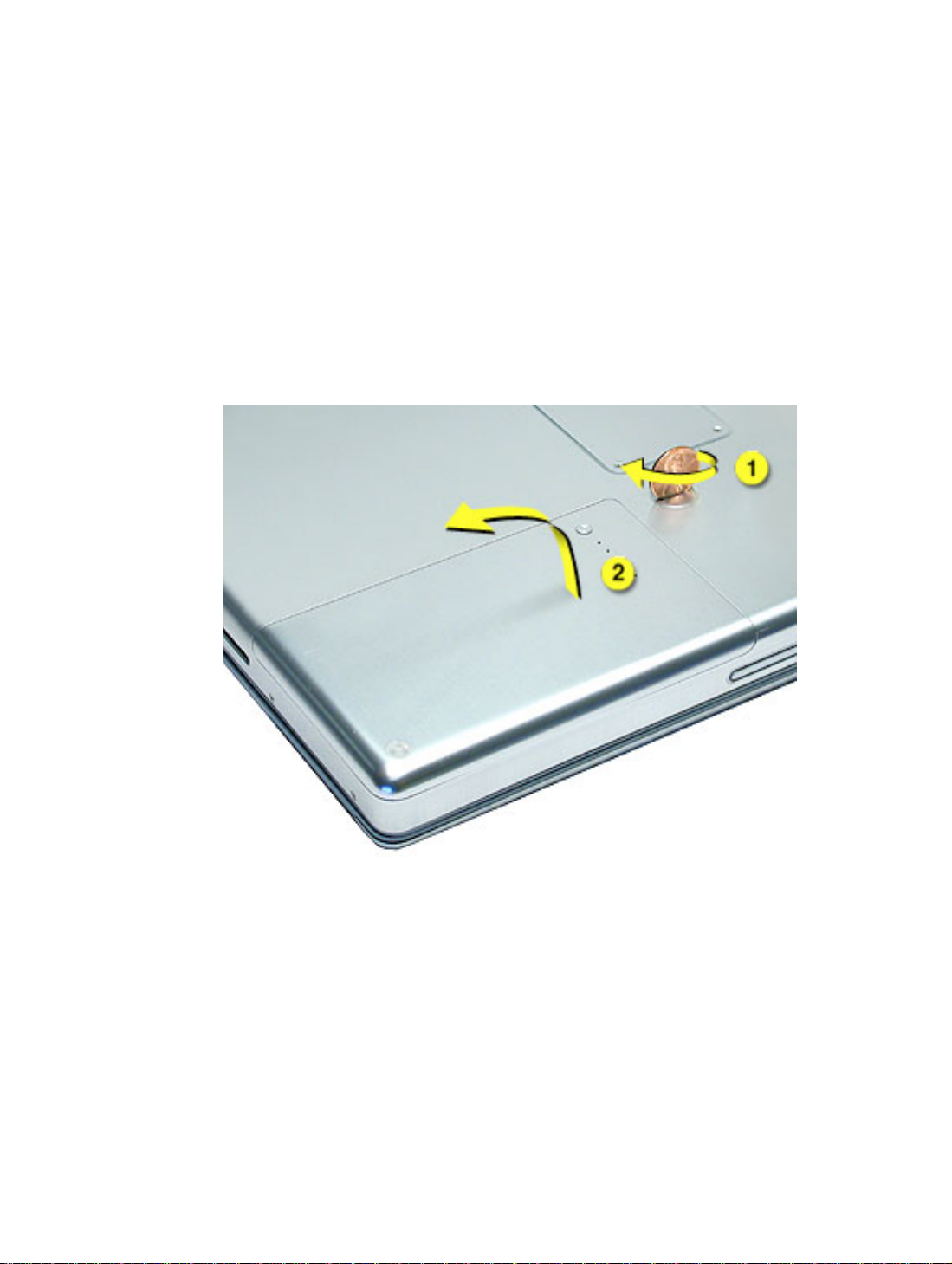
3. Turn over the computer and place it on a soft cloth.
4. Use a coin to release the battery lock.
5. Lift the battery out of the battery bay.
If the computer has been recently operating, allow it to cool down before
computer.
6. Install the replacement battery, and reassemble and test the computer.
6 -
PowerBook G4 (12-inch) Take Apart
Battery
Feet
Tools
This procedure requires the following tools:
• Foot kit
• Tweezers or needlenose pliers
• Soft cloth
Preliminary Step
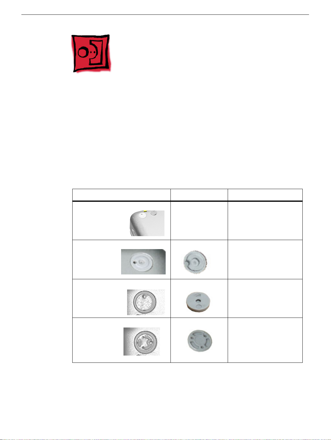
Before you begin, identify the type of foot that needs replacement. Check the bottom case
of the computer, and compare it with the images in this table:
Plug Area on Bottom Case Matching Foot Action
Missing plug Not available for
replacement
Battery plug Battery foot Continue with the
Case plug Case foot Continue with the
Case plug Case foot Continue with the
Do not perform the foot
replacement.
procedure, matching
the foot to the plug on
the battery.
procedure, matching
the foot to the plug on
the bottom case.
procedure, matching
the foot to the plug on
the bottom case.
Feet
PowerBook G4 (12-inch) Take Apart -
7
Procedure
Warning: The glue used in this procedure can bond instantly to skin. Do not touch the
glue. In the event of contact, review the safety instructions at the end of this document. For
additional information, refer to the glue manufacturer:
Elmer's Products, Inc.
Columbus, OH. 43215-3799
www.krazyglue.com
1. Place the computer upside down on a clean, lint-free cloth or other nonabrasive
surface.
2. Select a foot from the kit that matches the plug on the bottom case. (Refer to the
images shown in the table.) Do not use a foot that does not match.
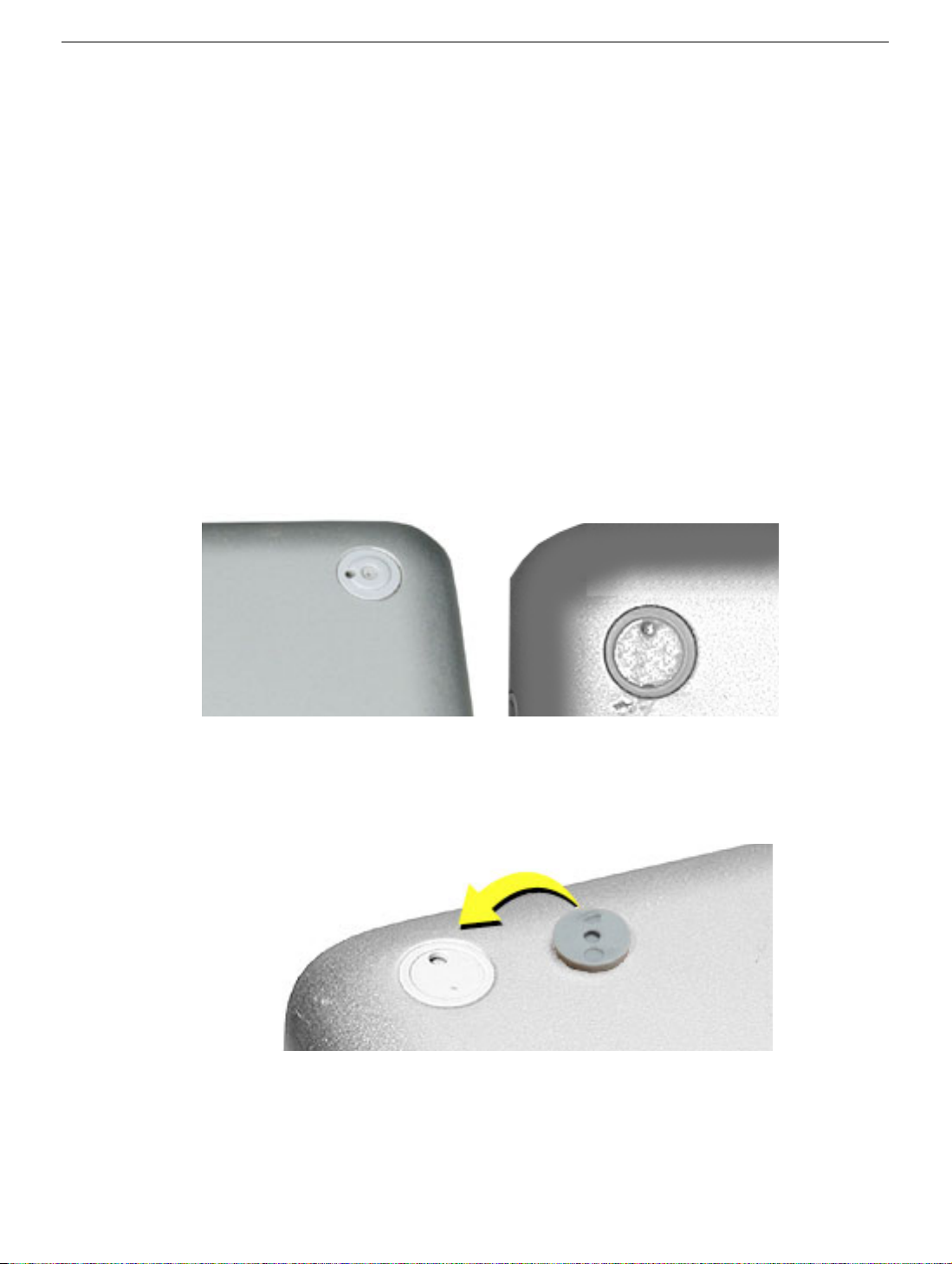
3. Make sure the plug area on the bottom case is clean. If any portion of the soft rubber
foot remains, remove it so that only the hard plastic plug is visible (as shown below).
Battery Plug Case Plug
Important: Notice the inner ring of the plug. When positioning the foot, make sure
the textured plane of the rubber foot fits into the compatible ring in the plug. This
ensures a balanced and level fitting.
8 - PowerBook G4 (12-inch) Take Apart
Feet

4. Warning: GLUE IS AN EYE AND SKIN IRRITANT. BONDS SKIN INSTANTLY. Do not
touch the glue at any time. Before opening the glue, review the safety instructions at
the end of this document.
Important: The glue tube included in the kit is sealed until first use. Do not break the
seal until you are ready to use the glue. To break the seal, hold the tube upright and
away from you. Place the hollow nozzle cap on the tube and tighten it all the way
down. The tube is then ready to dispense the glue through the nozzle cap.
5. Apply one drop of glue to the plug on the bottom case. Do not spread the glue.
6. Using tweezers or needlenose pliers, carefully position the new foot so its textured
surface fits into the inner ring of the plug.
7. Using the end of the tweezers or pliers—not your finger—lightly press and hold the
foot in place for 30 seconds.
8. Before turning over the computer, allow the glue to set for at least 15 minutes.
9. Discard the tube of glue.
SAFETY INSTRUCTIONS: GLUE IS AN EYE AND SKIN IRRITANT. BONDS SKIN
INSTANTLY. Contains ethyl cyanoacrylate. Avoid contact with skin and eyes. If eye or
mouth contact occurs, hold eyelid or mouth open and rinse thoroughly but gently with
water only for 15 minutes and GET MEDICAL ATTENTION. Liquid glue will sting eye
temporarily. Solidified glue may irritate eye like a grain of sand and should be treated by an
eye doctor. If skin bonding occurs, soak in acetone-based nail polish remover or warm
soapy water and carefully peel or roll skin apart (do not pull). Contact through clothing may
cause skin burn. If spilled on clothing, flush with cold water. Avoid prolonged breathing of
vapors. Use with adequate ventilation. KEEP OUT OF REACH OF CHILDREN.
Feet
PowerBook G4 (12-inch) Take Apart - 9

Memory Door and Memory Card
Tools
This procedure requires the following tools:
• Soft cloth
• #0 Phillips screwdriver
• Black stick (or other nonconductive nylon or plastic flat-blade tool)
Part Location
Preliminary Steps
Before you begin, remove the battery.
Procedure
Warning: If the computer has been recently operating, allow it to cool down before
performing this procedure.
10 - PowerBook G4 (12-inch) Take Apart
Memory Door and Memory Card
1. Place the computer upside down on a soft cloth.
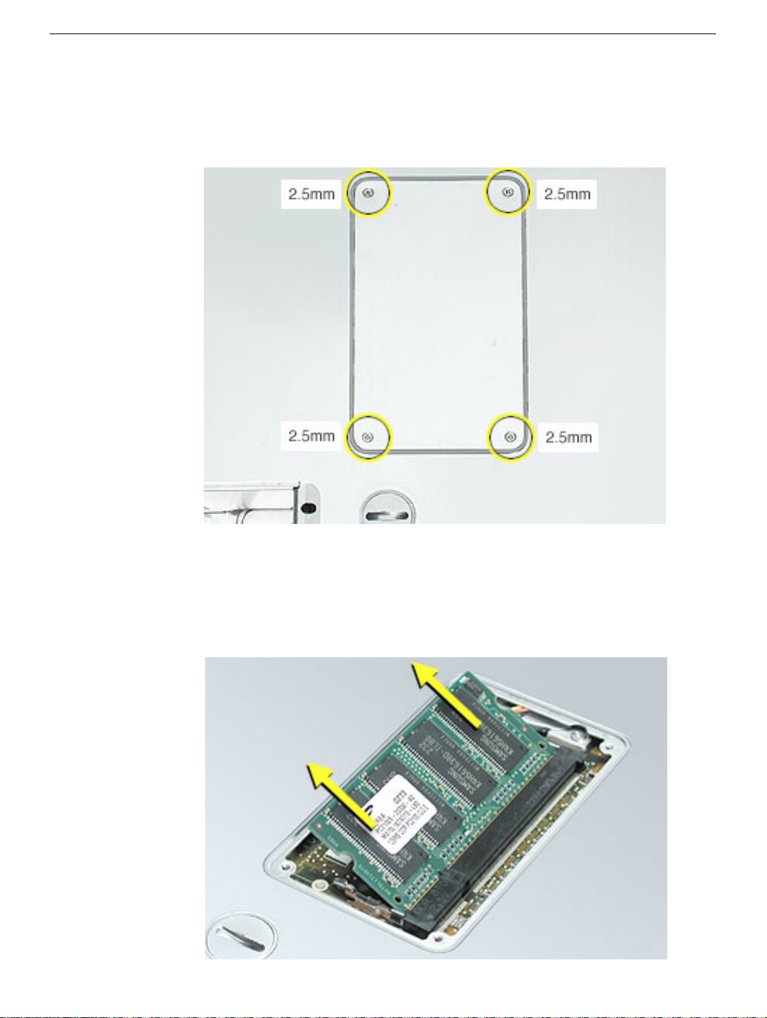
2. Remove the four identical screws from the memory door.
3. Use a black stick to lift off the memory door.
4. Touch a metal surface inside the computer to discharge static electricity from your
body.
5. If a memory card is already installed, release it by spreading apart the tabs in the
expansion slot from the notches in the card. Allow the card to pop up slightly, and pull
it out of the memory slot.
Memory Door and Memory Card
PowerBook G4 (12-inch) Take Apart - 11
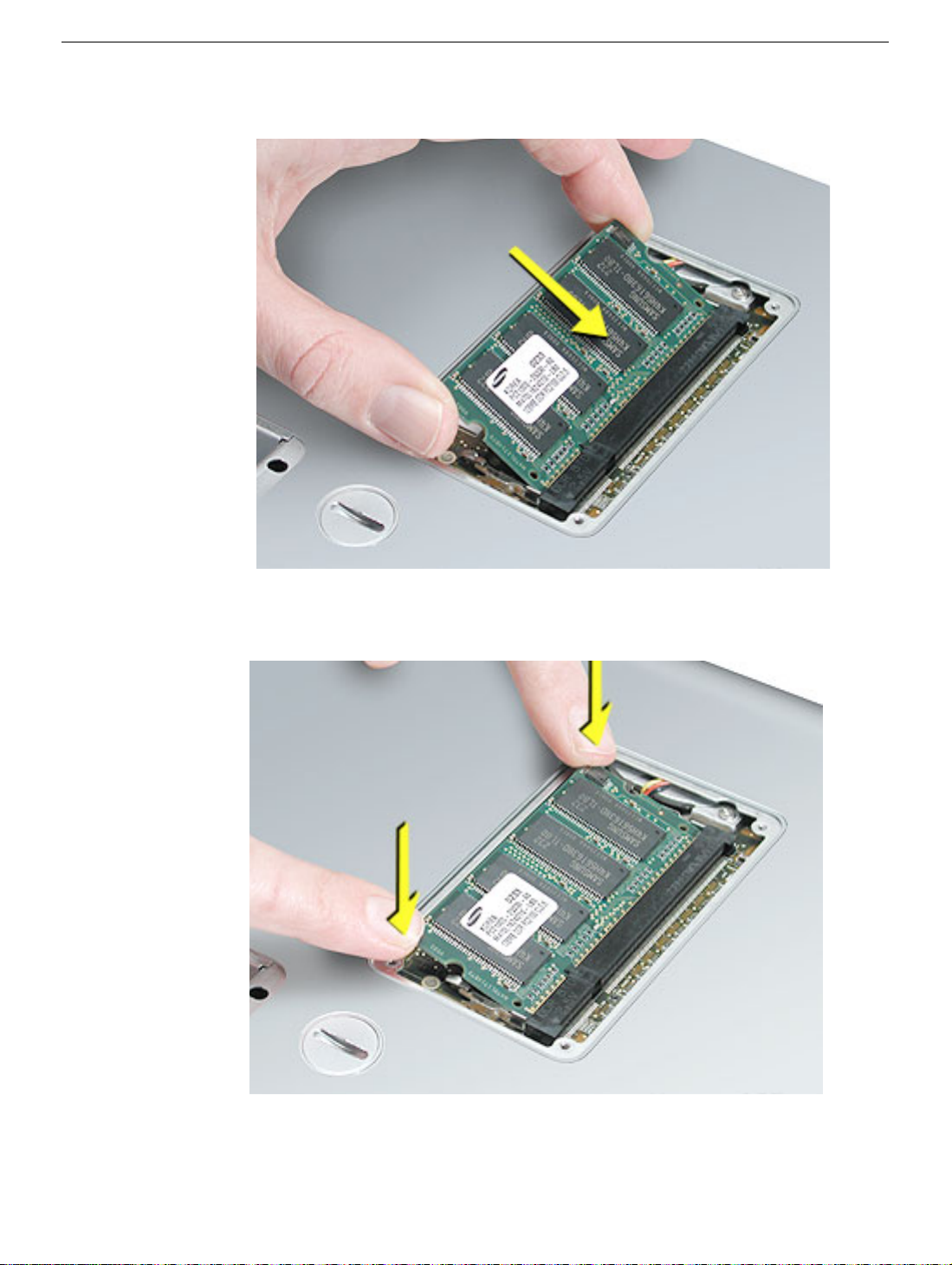
6. Insert the replacement memory card into the expansion slot at a 30-degree angle.
7. Make sure the memory card is fully inserted. Check that the notches in the card clear
the tabs as you press down on the sides of the card to lock it into place.
8. Install the memory door. Be careful not to overtighten the screws.
9. Install the battery, and test the computer.
12 - PowerBook G4 (12-inch) Take Apart
Memory Door and Memory Card
AirPort Extreme Card
Tools
This procedure requires a black stick (or other nonconductive nylon or plastic flat-blade
tool).
Part Location
Preliminary Steps
Before you begin, remove the battery.
AirPort Extreme Card
PowerBook G4 (12-inch) Take Apart - 13
Procedure
Warning: If the computer has been recently operating, allow it to cool down for 30
minutes before performing this procedure.
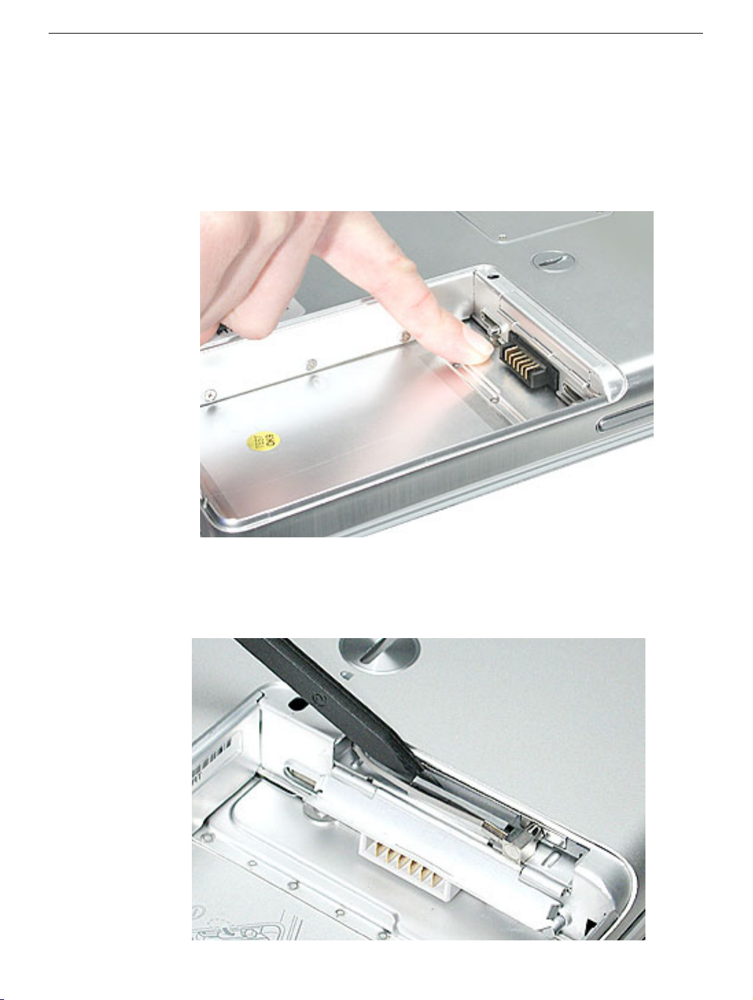
1. Touch a metal surface inside the battery bay to discharge static electricity from your
body.
2. Open the door to the AirPort slot.
3. If an optional AirPort Extreme Card is already installed, use a black stick to un-loop the
pull tab.
14 - PowerBook G4 (12-inch) Take Apart
AirPort Extreme Card
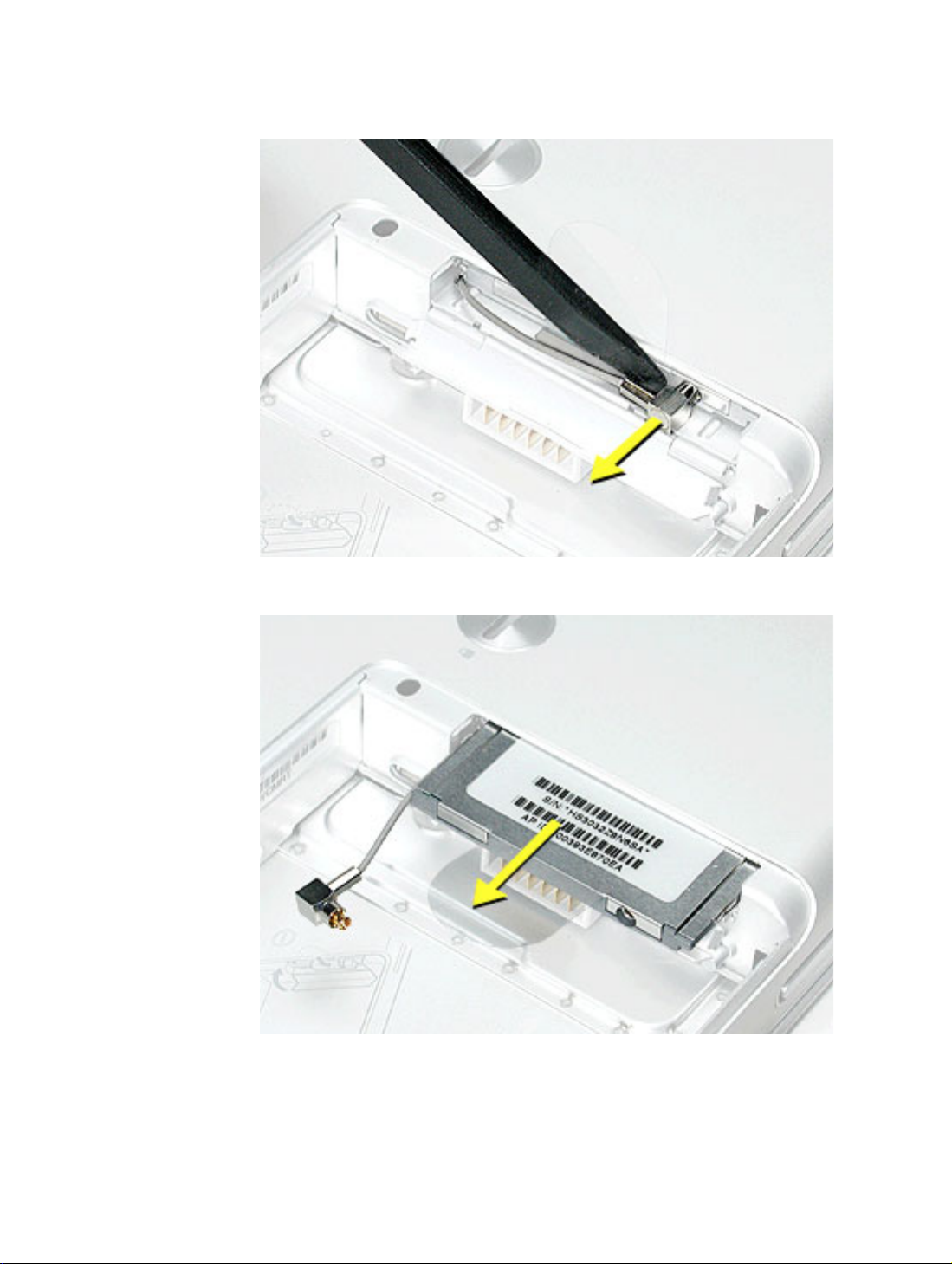
4. Gently disconnect the AirPort antenna cable.
5. Use the pull tab to pull out the card.
AirPort Extreme Card
PowerBook G4 (12-inch) Take Apart - 15

6. Slide the replacement AirPort Extreme Card with the serial number facing up into the
slot, as shown.
16 - PowerBook G4 (12-inch) Take Apart
AirPort Extreme Card
7. Connect the end of the antenna cable to the card.
8. Loop the clear plastic tab under the card so that the tab secures the antenna cable
and tucks into the slot.
Note:
The AirPort slot on the bottom case has a recessed inner slot designed for the
clear plastic tab to tuck into.
9. Close the AirPort door, and reassemble and test the computer.
AirPort Extreme Card
PowerBook G4 (12-inch) Take Apart - 17
Keyboard
Tools
This procedure requires the following tools:
• #0 Phillips screwdriver
• Black stick (or other nonconductive nylon or plastic flat-blade tool)
Note: To organize the screws you remove from the computer, use a tray with divided
compartments (such as a plastic ice cube tray).
Part Location
Preliminary Steps
Before you begin, remove the following:
• Battery
• Memory door and memory card
18 - PowerBook G4 (12-inch) Take Apart
Keyboard
Procedure
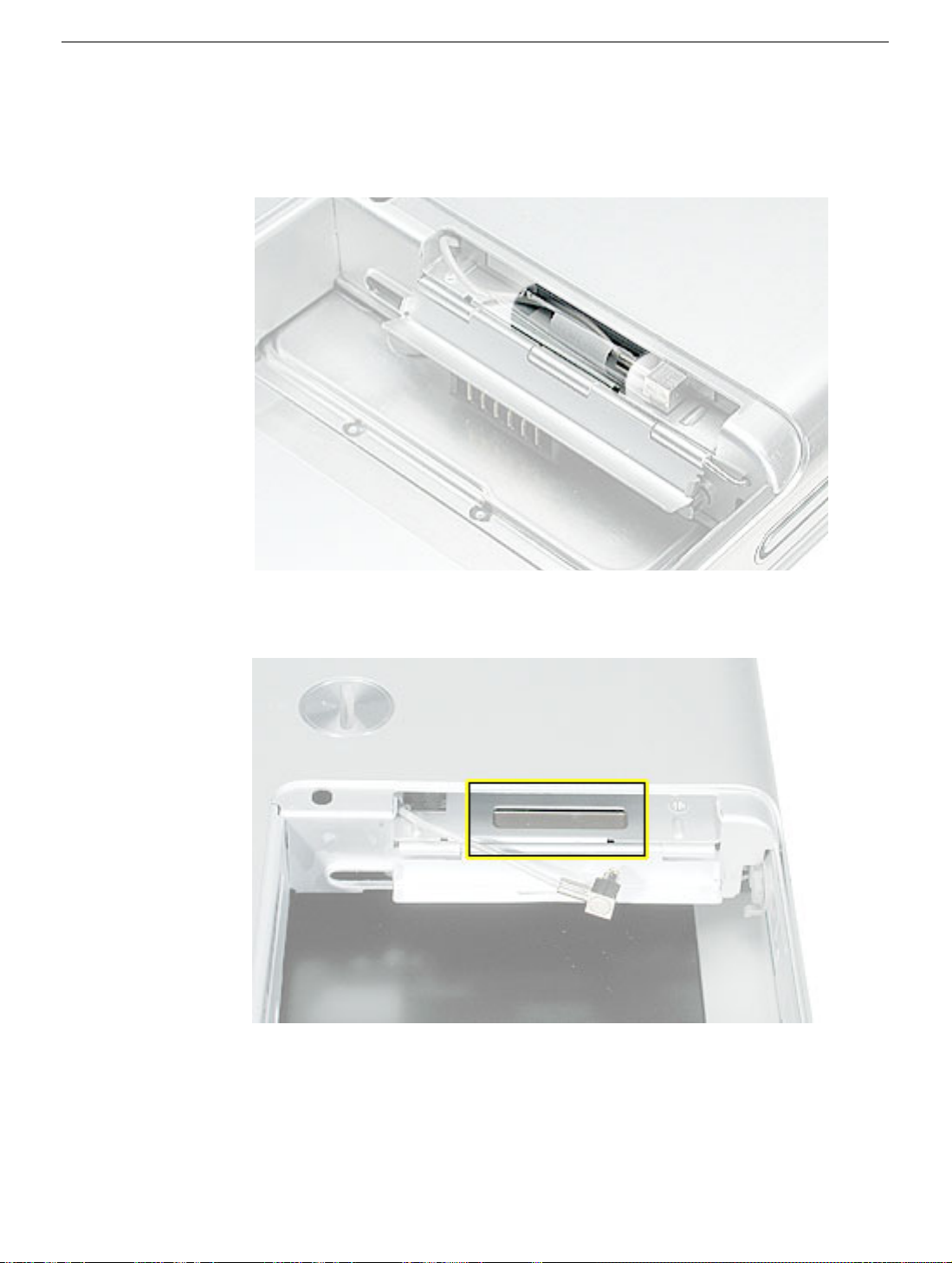
1. With the computer upside down on a soft cloth, remove the single screw and small
EMI shield from the memory card bay.
Replacement Note:
EMI shield is positioned with the finger-like projection pointing up.
Make sure you replace the screw and EMI shield so that the
Keyboard
PowerBook G4 (12-inch) Take Apart - 19
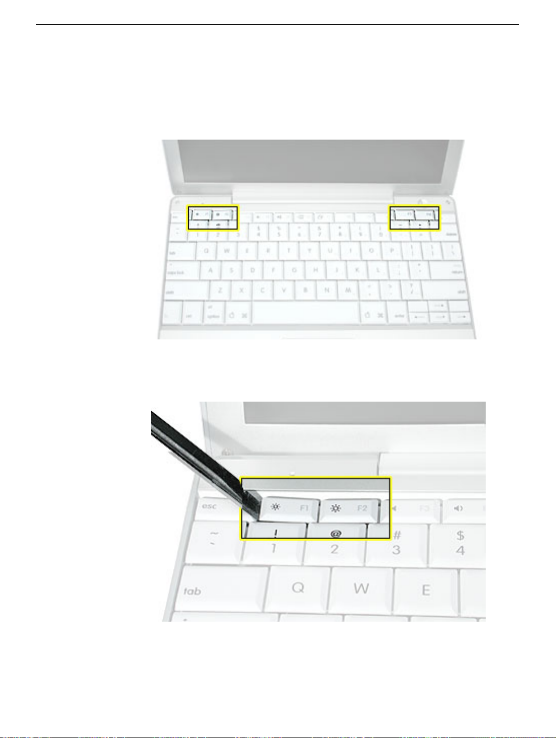
2. Open the computer, and locate the following keys:
•F1
•F2
• F11
• F12
3. Important:
of each key. The keys are easily removed from the left side without damaging the
keyboard.
Using a black stick, carefully pry up each of the four keys from the left side
20 - PowerBook G4 (12-inch) Take Apart
Keyboard
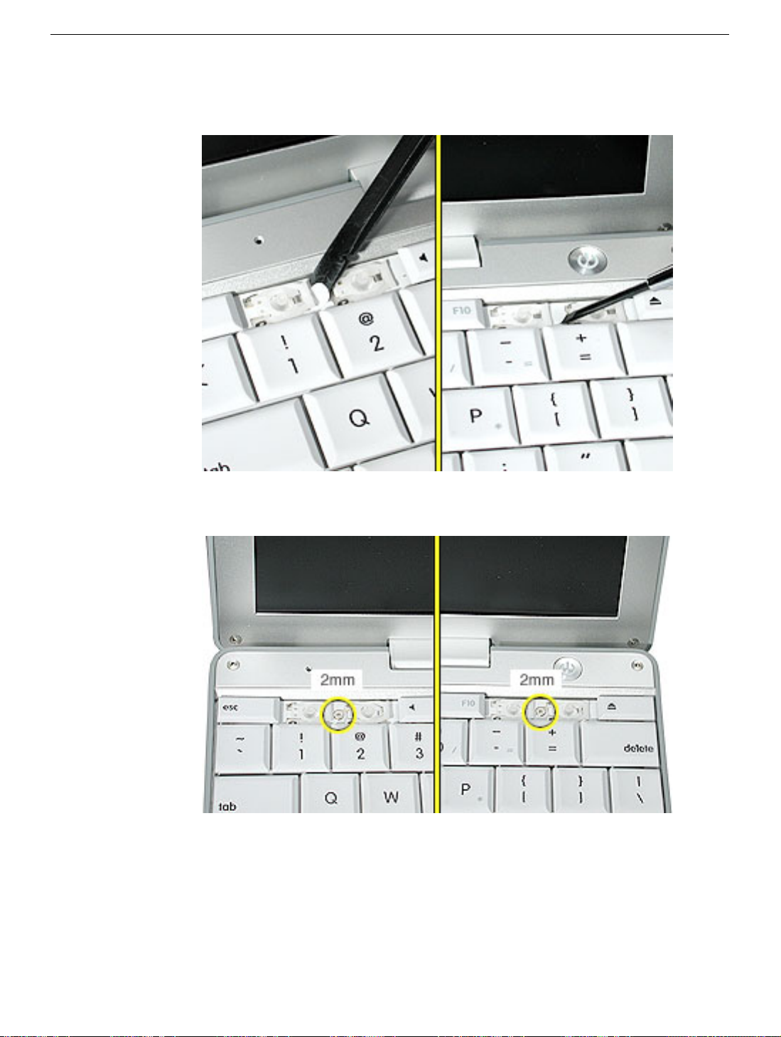
4. Use a black stick or flat-blade screwdriver to lift off the two round stickers that are
located between the two key mechanisms. Reserve the stickers for replacement.
5. Remove the screw under each of the stickers.
Keyboard
PowerBook G4 (12-inch) Take Apart - 21
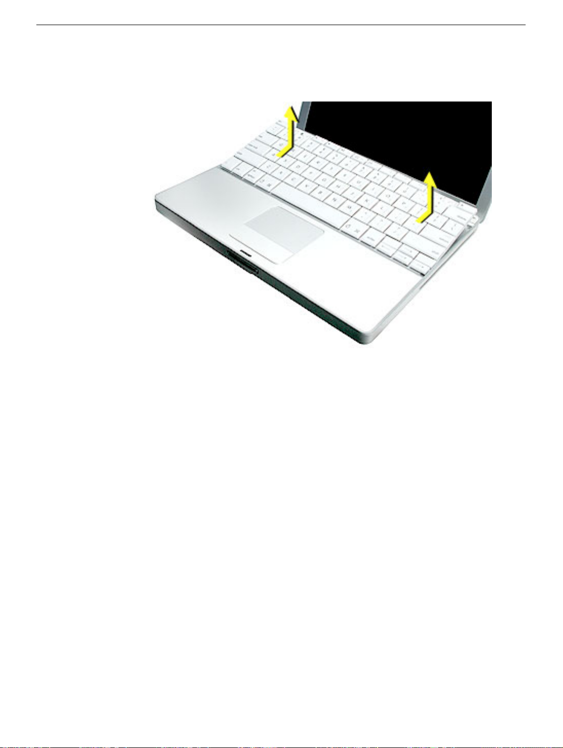
6. Lift up the top two corners of the keyboard, and move the keyboard toward the display
to clear the tabs at the bottom of the keyboard.
22 - PowerBook G4 (12-inch) Take Apart
Keyboard
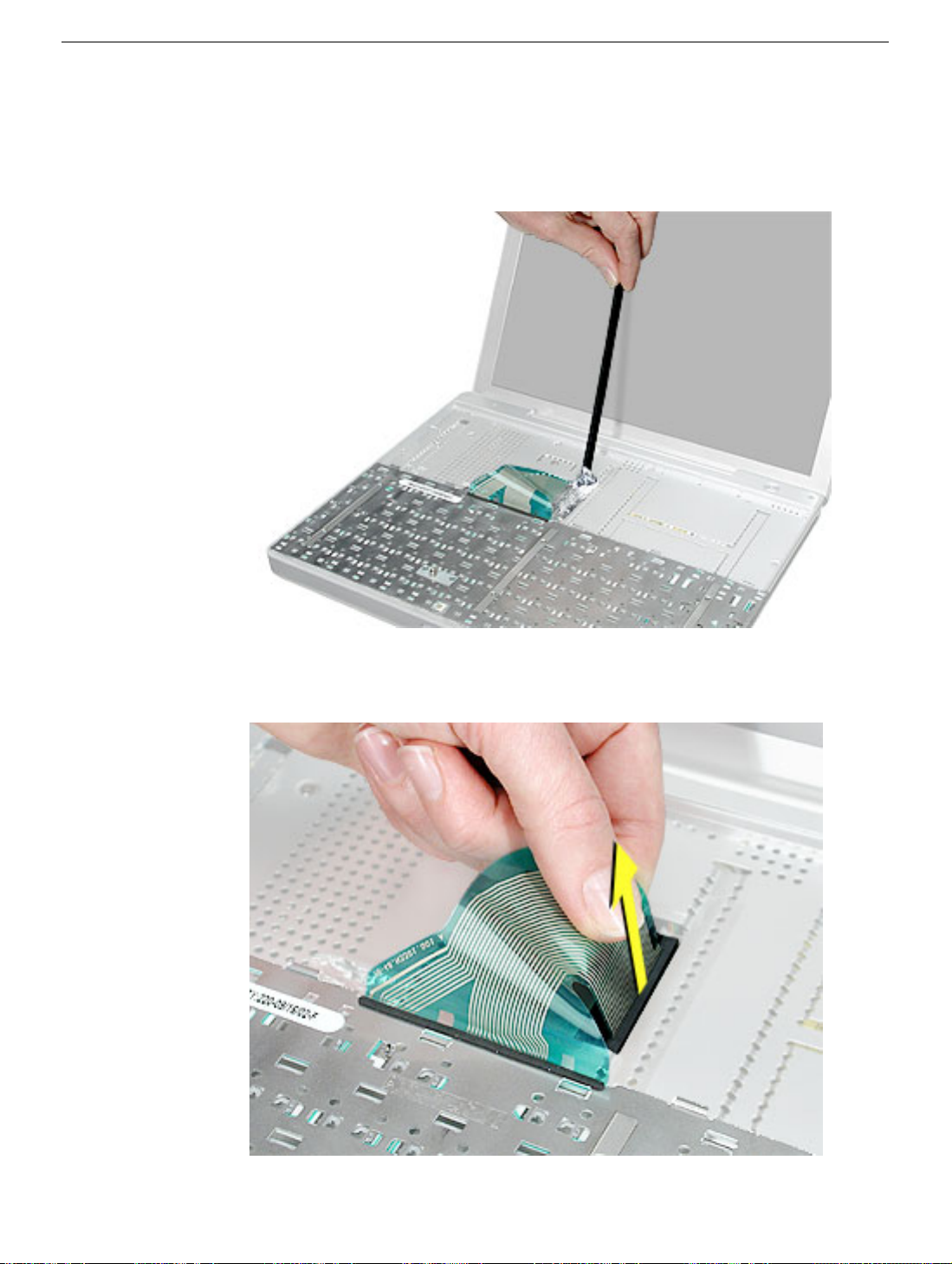
7. Flip the keyboard over and lay the keyboard flat on the trackpad.
8. Use a black stick to carefully remove the aluminum tape that covers the keyboard
connector. You will need to reuse the tape when reassembling the computer.
9. Peel up the keyboard cable from its adhesive. Using a black stick, pry up the tabs at
the ends of the connector, and then pull the cable straight up to disconnect it.
Keyboard
PowerBook G4 (12-inch) Take Apart - 23
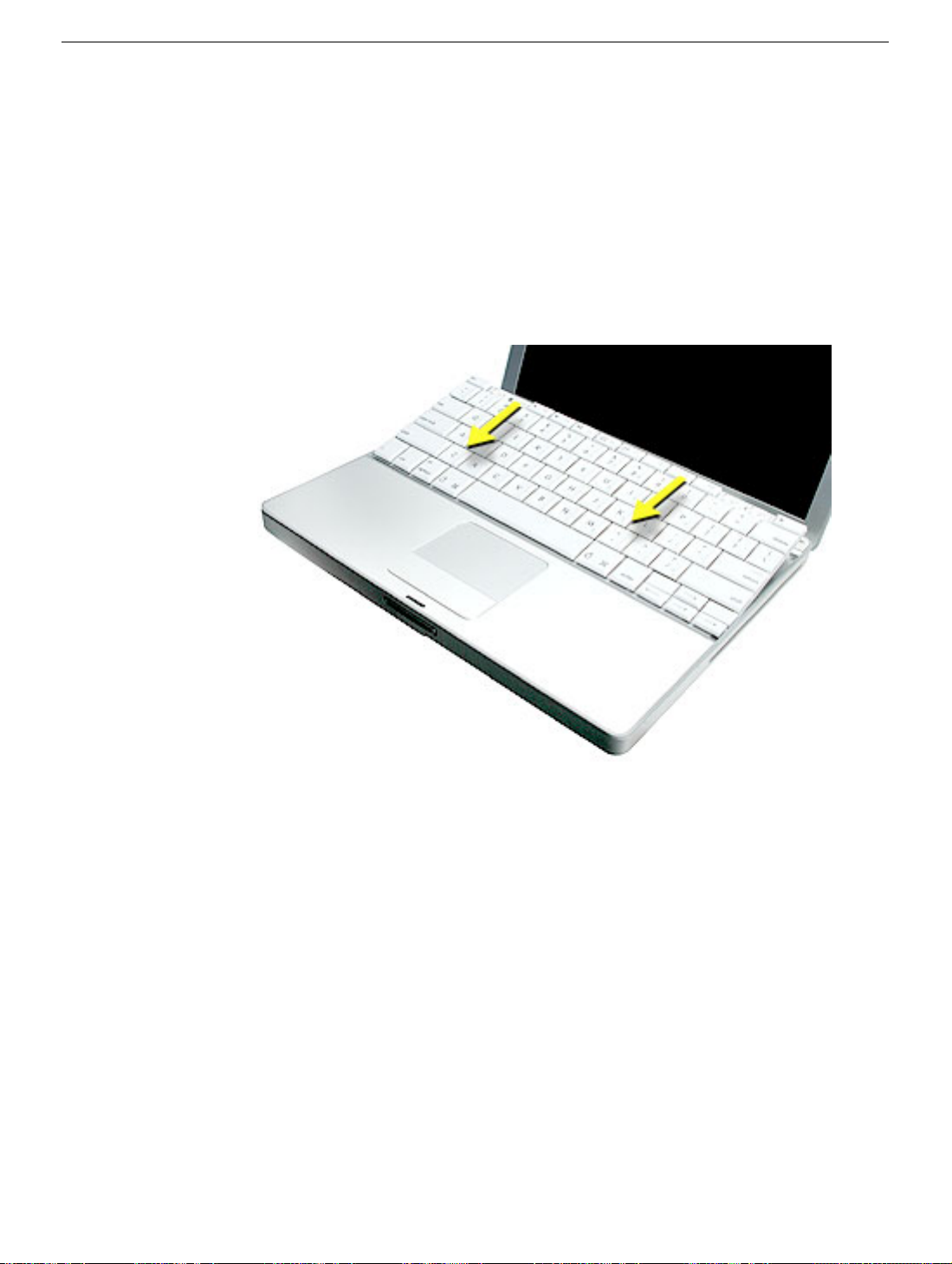
10. Install the replacement keyboard. Make sure you
• Install the foil tape in the recessed area over the keyboard connector.
• Set the tabs at the bottom of the keyboard into the slots in the top case.
• Press the keyboard into place, and install the screws and round stickers.
• Install the function keys:
– Position the key directly over the scissor mechanism.
– Press the key onto the scissor.
– Check the operation of the key.
• Close the display and install the final screw in the memory bay.
11. Reassemble and test the computer.
24 - PowerBook G4 (12-inch) Take Apart
Keyboard
Top Case
Tools
This procedure requires the following tools:
• #0 Phillips screwdriver
• Black stick (or other nonconductive nylon or plastic flat-blade tool)
• Hex 1.5 mm screwdriver
Note: To organize the screws you remove from the computer, use a tray with divided
compartments (such as a plastic ice cube tray).
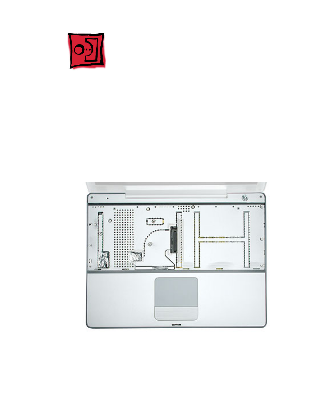
Part Location
Top Case
Preliminary Steps
Before you begin, remove the following:
• Battery
• Memory door and memory card
• Keyboard
PowerBook G4 (12-inch) Take Apart - 25
Procedure
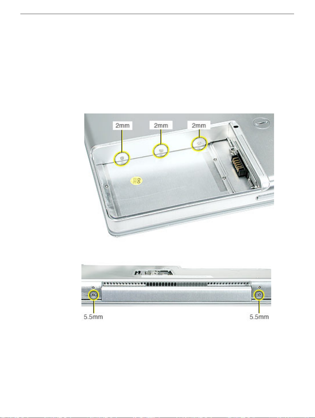
1. Warning: The screws in the battery bay require holding the screwdriver at an
angle. Be careful not to strip the screws.
Note: Avoid scratching the external housing by using care when removing the
screws. You might want to cover part of the housing with a soft cloth as you remove
screws.
With the computer upside down on a soft cloth, remove the three screws from the
bottom case at the battery bay.
2. Remove the screws near the display hinge.
26 - PowerBook G4 (12-inch) Take Apart
Top Case
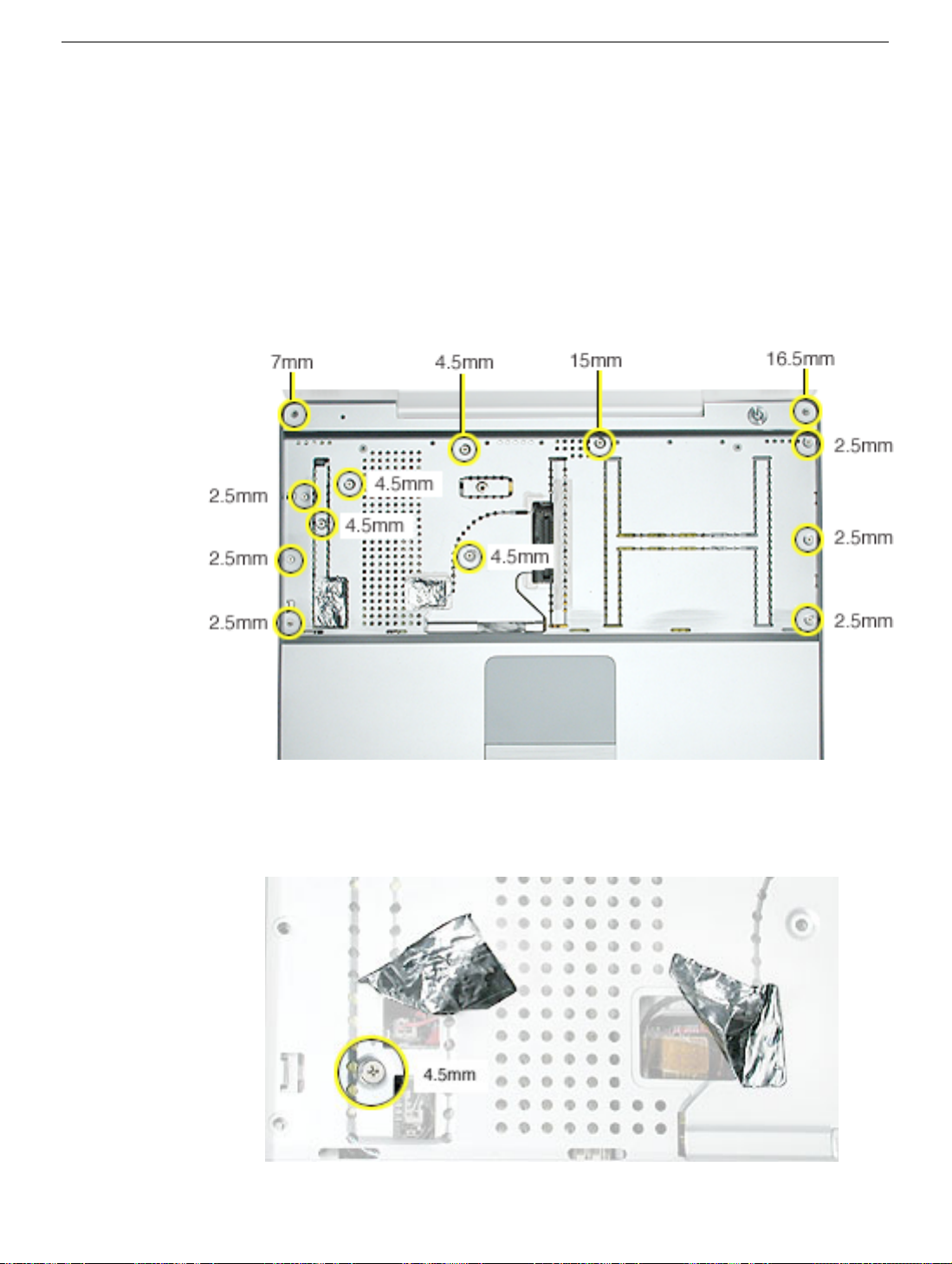
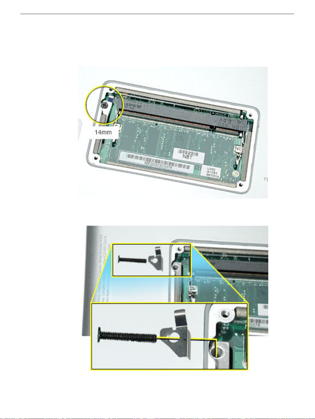
3. Open the display, and with the computer upright, remove the following 13 screws from
the top case:
• one Hex, 16.5 mm long screw at upper right corner near power button
• one Hex, 7 mm long screw at upper left corner near microphone
• one #0 Phillips, 15 mm long screw in keyboard well
• four #0 Phillips, 4.5 mm long screws in keyboard well
• six #0 Phillips, 2.5 mm long screws in keyboard well
Replacement Note: When replacing the top case screws, install the three 2.5-mm
long screws at the right side (optical drive side) first.
Top Case
4. Carefully peel up the two pieces of foil tape that cover the microphone cable, power
cable, and trackpad cable. Reserve the tape when reassembling the computer.
5. Remove the remaining screw from the top case.
PowerBook G4 (12-inch) Take Apart - 27
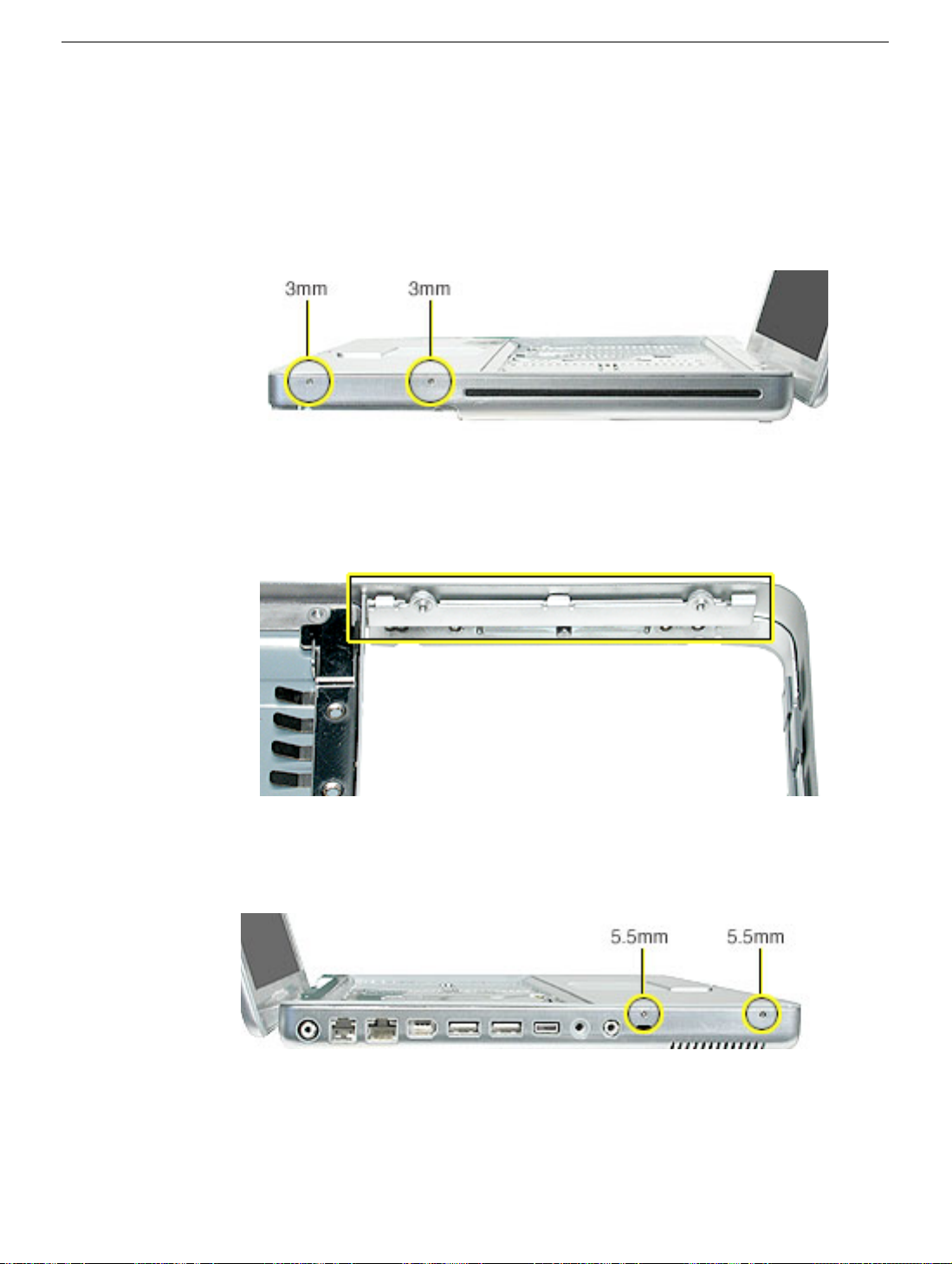
6. Remove two screws from the front right side of the top case.
Note: For the PowerBook G4 (12-inch DVI) model, the shape of the two 3-mm long
screws differs from the screws used in the PowerBook G4 (12-inch) model at this
location. Although the screw length is the same; the screw has a collar under the
screw head, and this type of screw cannot be used in the PowerBook G4 (12-inch)
model.
Replacement Note: In addition to securing the top case to the bottom case, the two
3-mm long screws help secure an inner bracket to the battery well. Make sure the
bracket is installed in the bottom case before replacing the top case.
7. Remove two screws from the front left side of the top case.
Replacement Note: When installing the top case, install these two 5.5-mm long
screws before installing the 3-mm long screws.
28 - PowerBook G4 (12-inch) Take Apart
Top Case

8. Use a black stick running along the edge of the top case to loosen—but not remove—
the top case from the bottom case. Use equal pressure at the front, left, and right
corners.
Top Case
PowerBook G4 (12-inch) Take Apart - 29

9. In the keyboard well, pull up the looped end of the trackpad cable to disconnect it.
10. Raise the top case up slightly from the bottom case until you can access the cables
that are connected under the top case.
11. Important: Do not forcefully remove the top case.
With the cables still connected, carefully move the top case aside to disconnect the
microphone cable and power cable.
12. Remove the top case from the computer.
30 - PowerBook G4 (12-inch) Take Apart
Top Case

13. The top case includes the following:
• Microphone cable
• Trackpad and trackpad cable
• Power button and cable
• Tape
• Welded EMI strips
• Magnet in keyboard well
Top Case
PowerBook G4 (12-inch) Take Apart - 31

14. Before installing a replacement top case, check the cable routing of the
• Microphone cable
• Trackpad cable
• Power button cable
Make sure the cables are routed correctly and cannot be pinched when installing the
top case.
15. Install the replacement top case, and reassemble and test the computer.
32 - PowerBook G4 (12-inch) Take Apart
Top Case

Reed Switch Board and Cable: PowerBook G4 (12-inch)
Tools
This procedure requires the following tools:
• Phillips #0 screwdriver
• Black stick (or other nonconductive nylon or plastic flat-blade tool)
Part Location
Preliminary Steps
Before you begin, remove the following:
• Battery
• Memory door and memory card
• Keyboard
• Top case
Reed Switch Board and Cable: PowerBook G4 (12-
PowerBook G4 (12-inch) Take Apart - 33

Procedure
1. Remove the screw from the reed switch board.
Warning:
screw could scratch the optical media.
2. Tilt the board up and away from the tab at the battery area.
3. Lift up the tape from the corner of the optical drive, if provided.
4. Disconnect the 3-pin connector from CN4 at the DC-to-DC board.
When replacing the board, make sure you use the same screw. A longer
5. Install the replacement reed switch board and cable, and reassemble and test the
computer.
34 - PowerBook G4 (12-inch) Take Apart
Reed Switch Board and Cable: PowerBook G4 (12-

Hall Effect Sensor Board and Cable: PowerBook G4 (12-inch DVI)
Tools
This procedure requires the following tools:
• Phillips #0 screwdriver
• Black stick (or other nonconductive nylon or plastic flat-blade tool)
Part Location
Preliminary Steps
Before you begin, remove the following:
• Battery
• Memory door and memory card
• Keyboard
• Top case
Hall Effect Sensor Board and Cable: PowerBook G4
PowerBook G4 (12-inch) Take Apart - 35

Procedure
1. Remove the screw from the hall effect sensor board.
Warning:
screw could scratch the optical media.
2. Remove the tape, if provided, from the corner of the optical drive, and disconnect the
3-pin connector from CN4 at the DC-to-DC board.
3. Remove the board with cable from the computer assembly.
When replacing the board, make sure you use the same screw. A longer
4. Install the replacement hall effect sensor board and cable, and reassemble and test
the computer.
36 - PowerBook G4 (12-inch) Take Apart
Hall Effect Sensor Board and Cable: PowerBook G4

Hard Drive
Tools
This procedure requires the following tools:
• #0 Phillips screwdriver
• Black stick (or other nonconductive nylon or plastic flat-blade tool)
Note: To organize the screws you remove from the computer, use a tray with divided
compartments (such as a plastic ice cube tray).
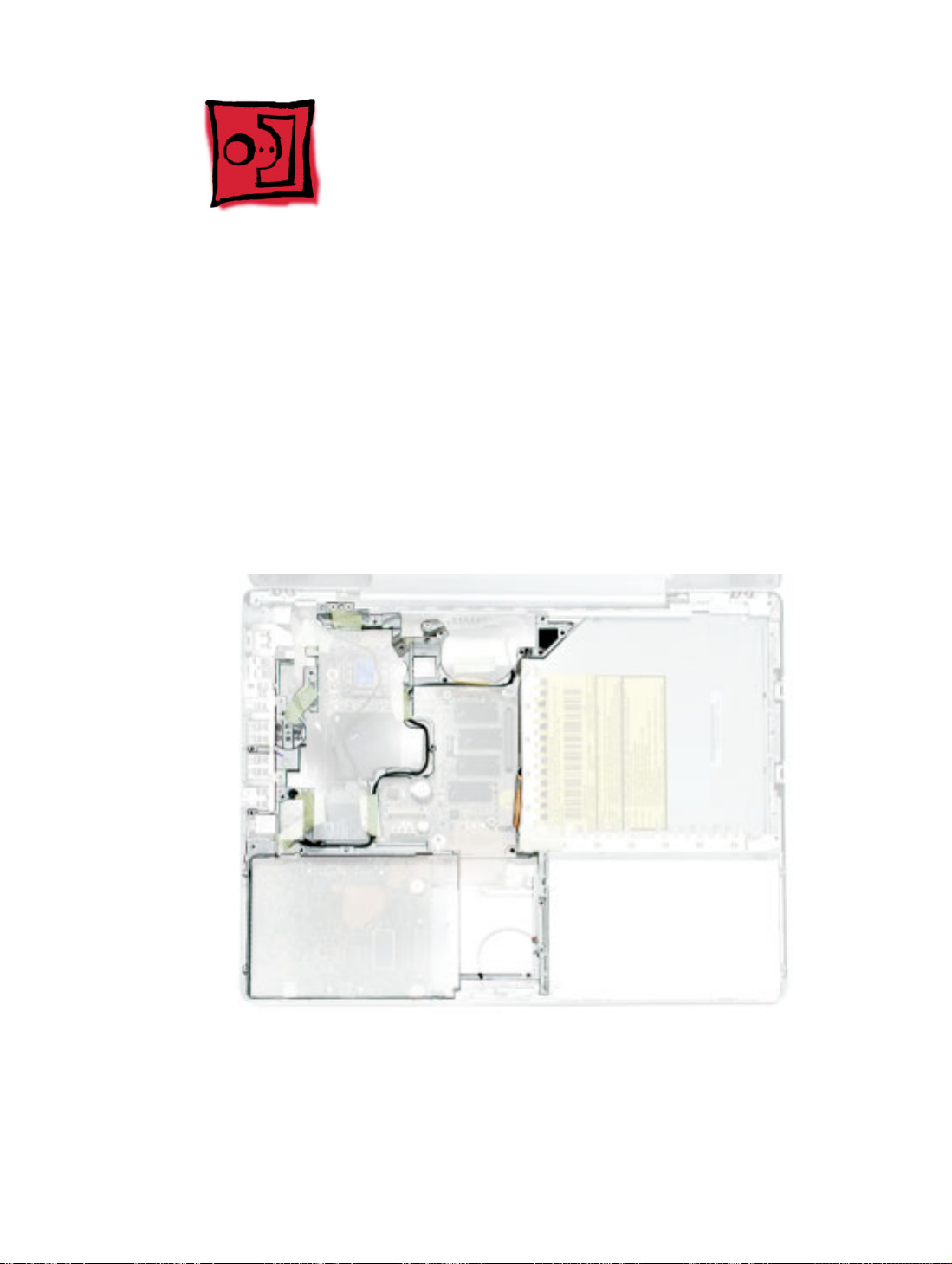
Part Location
Hard Drive
Preliminary Steps
Before you begin, remove the following:
• Battery
• Memory door and memory card
PowerBook G4 (12-inch) Take Apart - 37
• Keyboard
• Top case
Procedure
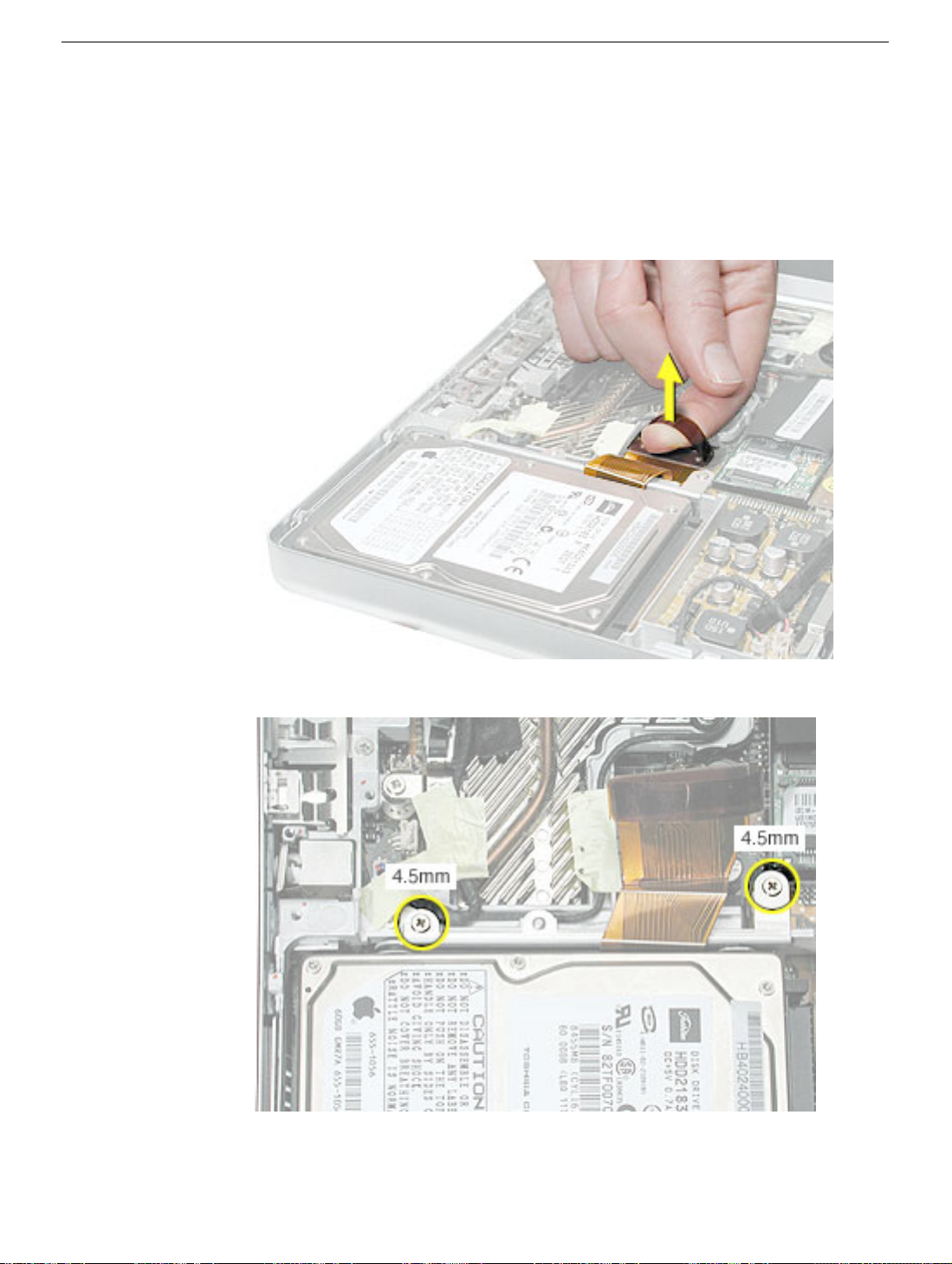
1. Disconnect the hard drive flex cable.
2. Remove two screws from the hard drive bracket.
38 - PowerBook G4 (12-inch) Take Apart
Hard Drive

3. Use the flex cable to lift up the hard drive, bracket, and cable from the computer
housing.
4. Turn over the hard drive and remove the two screws from the underside of the bracket.
Hard Drive
PowerBook G4 (12-inch) Take Apart - 39

5. Peel up the flex cable from its double-sided tape.
6. Use a black stick to pry the flex cable connector up slightly on each side, and then pull
it straight off the drive. Be careful not to bend any pins.
7. Remove the two screws and grommets from the opposite side of the drive.
8. Replacement Note: When installing the replacement drive, make sure the center
flange of the hard drive bracket fits over the small post on the computer frame.
9. Install the replacement hard drive, and reassemble and test the computer.
40 - PowerBook G4 (12-inch) Take Apart
Hard Drive

Modem
Tools
This procedure requires the following tools:
• #0 Phillips screwdriver
• Black stick (or other nonconductive nylon or plastic flat-blade tool)
Part Location
Modem
Preliminary Steps
Before you begin, remove the following:
• Battery
• Memory door and memory card
• Keyboard
• Top case
PowerBook G4 (12-inch) Take Apart - 41

Procedure
1. Remove the two screws from the modem board.
2. Use a black stick to tilt up the modem and disconnect it from the logic board.
42 - PowerBook G4 (12-inch) Take Apart
Modem

3. At the other end of the modem, disconnect the modem cable from the connector.
Replacement Note: When placing the replacement modem on the logic board, be sure to
align the board over the standoffs and connector on the logic board.
Modem
PowerBook G4 (12-inch) Take Apart - 43

Replacement Warning: For the PowerBook G4 (12-inch DVI) model, make sure you
reapply the transparent tape over the end of the modem so it overlaps the heatsink at the
bottom of the fan, as shown.
PowerBook G4 (12-inch DVI)
4. Install the replacement modem, and reassemble and test the computer.
Replacement Note: When reapplying tape around the fan, make sure the fan
blades are not blocked. The image below shows the correct application of tape.
44 - PowerBook G4 (12-inch) Take Apart
Modem

DC-to-DC Board
Tools
This procedure requires the following tools:
• #0 Phillips screwdriver (magnetized preferred)
• Black stick (or other nonconductive nylon or plastic flat-blade tool)
• 14 mm socket wrench or needlenose pliers
Note: To organize the screws you remove from the computer, use a tray with divided
compartments (such as a plastic ice cube tray).
Part Location
Note: Although this section pictures the DC-to-DC board used in the PowerBook G4 (12inch DVI) model, the procedure is the same for both models.
DC-to-DC Board
PowerBook G4 (12-inch) Take Apart - 45

Preliminary Steps
Before you begin, remove the following:
• Battery
• Memory door and memory card
• Keyboard
• Top case
• Hard drive
• Modem
Procedure
1. Disconnect the sleep light cable and the reed switch (or hall effect sensor board) cable
from the DC-to-DC board.
46 - PowerBook G4 (12-inch) Take Apart
DC-to-DC Board

2. Remove the three screws from the DC-to-DC board.
Note: When removing the 3 mm-long screw, the magnetic latch might draw the
screw toward it. The 14-mm long screw has a hex head and requires a
needlenose pliers or socket wrench to remove it.
Replacement Note: When replacing the DC-to-DC board, install the screws in a
clockwise direction, starting with the long hex head screw.
DC-to-DC Board
PowerBook G4 (12-inch) Take Apart - 47

3. Remove the two screws at the battery connector.
4. Lift off the EMI strip from the battery connector. Be sure to replace it when installing
the replacement DC-to-DC board.
48 - PowerBook G4 (12-inch) Take Apart
DC-to-DC Board

5. Place a black stick just under the top edge of the board at the modem standoff.
Disconnect the DC-to-DC board from the logic board by prying up the DC-to-DC board
and removing it from the computer assembly.
6. Install the replacement DC-to-DC board, and reassemble and test the computer.
DC-to-DC Board
PowerBook G4 (12-inch) Take Apart - 49

Heatsink and Fan Assembly: PowerBook G4 (12-inch)
Tools
This procedure requires the following tools:
• #0 Phillips screwdriver
• #1 Phillips screwdriver
• Black stick (or other nonconductive nylon or plastic flat-blade tool)
Note: To organize the screws you remove from the computer, use a tray with divided
compartments (such as a plastic ice cube tray).
Part Location
Preliminary Steps
Before you begin, remove the following:
• Battery
• Memory door and memory card
50 - PowerBook G4 (12-inch) Take Apart
Heatsink and Fan Assembly: PowerBook G4 (12-

• Keyboard
• Top case
• Modem
Procedure
1. Warning: The cone of the subwoofer, located below the heatsink and to the right of
the fan, is a sensitive device. Avoid touching the subwoofer cone as you perform this
procedure.
2. Peel up the tape if any of the following screws are covered. Remove the following
screws from the heatsink:
• Two 6 mm long #0 Phillips screws
• Two 7.5 mm long #1 Phillips screws with springs
• One 13 mm long #0 Phillips screw
• One 4.5 mm long #0 Phillips screw
Heatsink and Fan Assembly: PowerBook G4 (12-
PowerBook G4 (12-inch) Take Apart - 51

3. Remove the tape that covers the heatsink and secures the cables in place.
4. Near the fan, peel up the tape and remove the following screws:
• One 3 mm long screw
• One 6 mm long screw
• One 13 mm long screw
5. Peel up the yellow tape, and disconnect the inverter cable that runs along the top of
the fan from the logic board.
6. Remove the transparent tape at the bottom of the fan, and disconnect the fan cable.
Replacement Note: When installing the replacement heatsink assembly, note that
the fan cable is routed beneath the computer frame.
Replacement Warning: Make sure you apply the transparent tape over the bottom of
the fan so it covers the same area.
52 - PowerBook G4 (12-inch) Take Apart
Heatsink and Fan Assembly: PowerBook G4 (12-

7. Holding the heatsink at the crossbar, begin to lift up the heatsink assembly, being
careful where it catches on remaining tape and the chassis. Use a black stick to pry up
the middle right corner of the heatsink plate.
Warning:
8. Route the fan cable through the slot in the computer frame.
To avoid bending the heatsink, support the heatsink as it is removed.
Heatsink and Fan Assembly: PowerBook G4 (12-
PowerBook G4 (12-inch) Take Apart - 53

9. Note the routing of the remaining cables and the placement of tape once the heatsink
is removed.
.
10. Install the replacement heatsink and fan assembly, and reassemble and test the
computer.
Replacement Note: When reapplying tape around the fan, make sure the fan
blades are not blocked. The image below shows the correct application of tape.
54 - PowerBook G4 (12-inch) Take Apart
Heatsink and Fan Assembly: PowerBook G4 (12-

Heatsink: PowerBook G4 (12-inch DVI)
Tools
This procedure requires the following tools:
• #0 Phillips screwdriver
• #1 Phillips screwdriver
• Black stick (or other nonconductive nylon or plastic flat-blade tool)
Note: To organize the screws you remove from the computer, use a tray with divided
compartments (such as a plastic ice cube tray).
Part Location
Preliminary Steps
Before you begin, remove the following:
• Battery
• Memory door and memory card
• Keyboard
• Top case
• Modem
Heatsink: PowerBook G4 (12-inch DVI)
PowerBook G4 (12-inch) Take Apart - 55

Procedure
1. Warning: The cone of the subwoofer, located below the heatsink and to the right of
the fan, is a sensitive device. Avoid touching the subwoofer cone as you perform this
procedure.
2. Peel up the tape if any of the following screws are covered. Remove the following
screws from the heatsink:
• Three 6 mm long #0 Phillips screws
• Two 7.5 mm long #1 Phillips screws with springs
• Two 13 mm long #0 Phillips screws
• One 4.5 mm long #0 Phillips screw
56 - PowerBook G4 (12-inch) Take Apart
Heatsink: PowerBook G4 (12-inch DVI)

3. Near the fan, peel up the tape that secures the cables to the heatsink.
4. Remove the 3mm-long screw that secures the inverter cable to the frame.
5. Disconnect the inverter cable that runs along the top of the fan from the logic board.
6. Use a black stick to pry up the lower right side of the heatsink plate. Holding the
heatsink at the crossbar, begin to lift up the heatsink assembly, being careful where it
catches on remaining tape and the chassis.
Warning: To avoid bending the heatsink, support the heatsink as it is removed.
Heatsink: PowerBook G4 (12-inch DVI)
PowerBook G4 (12-inch) Take Apart - 57

7. Check the thermal pads on the heatsink:
• If you are performing another module replacement and will be using the existing
heatsink, peel away the thermal pads on the underside of the heatsink, and apply
new thermal pads in the orientation shown.
• If you are installing a replacement heatsink, make sure that the thermal pads are
correctly installed as shown.
Note: If any thermal pad residue remains on the logic board, use a black stick to
carefully peel it away.
8. When installing the heatsink, first insert the lower flange of the heatsink panel under
the frame.
58 - PowerBook G4 (12-inch) Take Apart
Heatsink: PowerBook G4 (12-inch DVI)

9. Install the replacement heatsink, and secure the screws using the following sequence:
Warning: Check the screw lengths before installing the screws. Installing a
longer screw in the wrong place can permanently damage the bottom case or
an internal part.
• Install the two 7.5-mm long spring screws half way.
• Install the remaining screws in the order indicated by the circled numbers in the
following image.
• Tighten the two 7.5-mm long spring screws the rest of the way.
10. Reassemble and test the computer.
Heatsink: PowerBook G4 (12-inch DVI)
PowerBook G4 (12-inch) Take Apart - 59
Inner Frame: PowerBook G4 (12-inch)
Tools
This procedure requires the following tools:
• #0 Phillips screwdriver
• Black stick (or other nonconductive nylon or plastic flat-blade tool)
Note: To organize the screws you remove from the computer, use a tray with divided
compartments (such as a plastic ice cube tray).
Part Location
Preliminary Steps
Before you begin, remove the following:
• Battery
• Memory door and memory card
• Keyboard
60 - PowerBook G4 (12-inch) Take Apart
Inner Frame: PowerBook G4 (12-inch)

• Top case
• Reed switch
• Hard drive
• Modem
• DC-to-DC board
• Heatsink with fan
Procedure
1. Note the cable routing and placement of tape before disconnecting cables.
Replacement Note: Reserve the tape for securing cables after the frame
replacement.
Inner Frame: PowerBook G4 (12-inch)
PowerBook G4 (12-inch) Take Apart - 61

2. Warning: The subwoofer cone, located below the right corner of the frame, is a
sensitive device. Avoid touching the cone as you perform this procedure.
3. Disconnect the connector from the upper right corner of the logic board.
4. Remove the screw near the right corner of the frame.
5. Near the I/O ports, disconnect the
• long black cable from the 2-pin connector
• shorter black cable from the 4-pin connector
62 - PowerBook G4 (12-inch) Take Apart
Inner Frame: PowerBook G4 (12-inch)

6. Pull up the LVDS cable with the pull tab
Warning: Be careful not to strain the LVDS cable.
7. Remove the screw at the LVDS cable.
Replacement Note: When reinstalling the LVDS cable, tuck the pull tab under the
frame.
Inner Frame: PowerBook G4 (12-inch)
PowerBook G4 (12-inch) Take Apart - 63

8. Peel up the tape, and remove the screw at the RJ11 modem cable board.
9. Tilt up the RJ11 modem cable board and remove the 6-mm long screw (not shown)
that secures the frame to the logic board.
64 - PowerBook G4 (12-inch) Take Apart
Inner Frame: PowerBook G4 (12-inch)

10. Remove the two screws at the I/O ports.
11. Remove the EMI strip at the top of the I/O ports.
Inner Frame: PowerBook G4 (12-inch)
PowerBook G4 (12-inch) Take Apart - 65

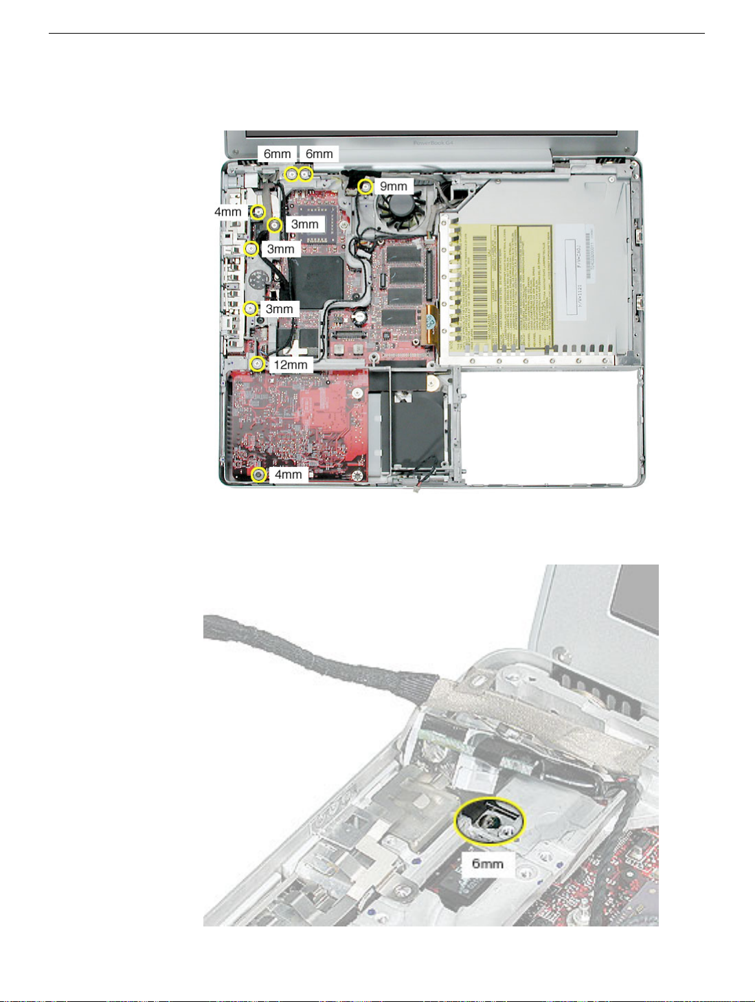
12. Remove the three screws from the top of the heatsink.
13. Remove the two screws from the lower left corner of the computer assembly.
66 - PowerBook G4 (12-inch) Take Apart
Inner Frame: PowerBook G4 (12-inch)

14. Disconnect the optical drive flex cable.
15. Lift up the frame, being careful where it catches on the optical drive flex cable or other
cables.
Inner Frame: PowerBook G4 (12-inch)
PowerBook G4 (12-inch) Take Apart - 67

16. Lift the inner frame out of the computer assembly.
17. Remove the tape that secures the RJ11 board and cable to both sides of the frame.
Transfer the RJ11 board and cable to the replacement frame.
68 - PowerBook G4 (12-inch) Take Apart
Inner Frame: PowerBook G4 (12-inch)

18. Install the replacement frame, and reassemble and test the computer.
Replacement Note: When installing the replacement frame, note the initial routing of
the cables, as shown in the following images:
Inner Frame: PowerBook G4 (12-inch)
PowerBook G4 (12-inch) Take Apart - 69

Inner Frame: PowerBook G4 (12-inch DVI)
Tools
This procedure requires the following tools:
• #0 Phillips screwdriver
• Black stick (or other nonconductive nylon or plastic flat-blade tool)
Note: To organize the screws you remove from the computer, use a tray with divided
compartments (such as a plastic ice cube tray).
Part Location
Preliminary Steps
Before you begin, remove the following:
• Battery
• Memory door and memory card
• Keyboard
70 - PowerBook G4 (12-inch) Take Apart
Inner Frame: PowerBook G4 (12-inch DVI)

• Top case
• Reed switch
• Hard drive
• Modem
• DC-to-DC board
• Heatsink
Procedure
1. Note the cable routing before disconnecting cables.
Replacement Note: Reserve the tape for securing cables after the frame
replacement.
Inner Frame: PowerBook G4 (12-inch DVI)
PowerBook G4 (12-inch) Take Apart - 71

2. Warning: The subwoofer cone, located below the right corner of the frame, is a
sensitive device. Avoid touching the cone as you perform this procedure.
3. Disconnect the connector from the upper right corner of the logic board.
4. Remove the screw near the right corner of the frame.
72 - PowerBook G4 (12-inch) Take Apart
Inner Frame: PowerBook G4 (12-inch DVI)

5. Warning: Be careful not to strain the LVDS cable.
Near the I/O ports,
• disconnect the LVDS cable by using the pull-tab on the connector
• disconnect the 6-pin connector
Replacement Note: When reinstalling the LVDS cable, tuck the pull-tab under the
frame.
Inner Frame: PowerBook G4 (12-inch DVI)
PowerBook G4 (12-inch) Take Apart - 73

6. Near the fan, disconnect the two connectors shown
• four-pin connector
• two-pin connector
Replacement Warning: When reassembling the computer, notice the two black
insulated cables that run along the bottom of the fan. To avoid damaging the
cables, make sure that the thinner twisted cable is routed on top of the
thicker fan cable and that both cables are routed between the fan and the
modem standoff, as shown.
74 - PowerBook G4 (12-inch) Take Apart
Inner Frame: PowerBook G4 (12-inch DVI)
7. Peel up any remaining tape, and remove the screws from the frame and I/O port
shield.
8. Tilt up the RJ11 modem cable board and remove the 6-mm long screw (normally
hidden by the RJ11 board).
Inner Frame: PowerBook G4 (12-inch DVI)
PowerBook G4 (12-inch) Take Apart - 75

9. Disconnect the optical drive flex cable.
10. Lift up the frame, being careful where it catches on the optical drive flex cable or other
cables.
76 - PowerBook G4 (12-inch) Take Apart
Inner Frame: PowerBook G4 (12-inch DVI)

11. Lift the inner frame out of the computer assembly.
Inner Frame: PowerBook G4 (12-inch DVI)
PowerBook G4 (12-inch) Take Apart - 77

12. Remove the tape that secures the RJ11 board and cable to both sides of the frame.
Transfer the RJ11 board and cable to the replacement frame.
13. Remove the screws from the fan. Transfer the fan to the replacement frame. (Refer to
"Fan" in this chapter.)
Replacement Note: Check that the replacement frame includes a thermal pad next
to the fan, as shown by the blue square in the following image.
78 - PowerBook G4 (12-inch) Take Apart
Inner Frame: PowerBook G4 (12-inch DVI)

14. Install the replacement frame, and reassemble and test the computer.
Replacement Note: Make sure you install the top EMI strip at the port side of the
replacement frame.
Inner Frame: PowerBook G4 (12-inch DVI)
PowerBook G4 (12-inch) Take Apart - 79

RJ11 Modem Board and Cable: PowerBook G4 (12-inch)
Tools
This procedure requires the following tools:
• #0 Phillips screwdriver
• Black stick (or other nonconductive nylon or plastic flat-blade tool)
Note: To organize the screws you remove from the computer, use a tray with divided
compartments (such as a plastic ice cube tray).
Part Location
Preliminary Steps
Before you begin, remove the following:
• Battery
• Memory door and memory card
• Keyboard
80 - PowerBook G4 (12-inch) Take Apart
RJ11 Modem Board and Cable: PowerBook G4 (12-

• Top case
• Reed switch
• Hard drive
• Modem
• DC-to-DC board
• Heatsink with fan
• Inner Frame
Procedure
1. With the inner frame removed from the computer, remove the tape that secures the
RJ11 board and cable to both sides of the frame.
Replacement Note: Reapply the tape to the frame. Refer to the RJ11 cable routing
in the images below.
RJ11 Modem Board and Cable: PowerBook G4 (12-
PowerBook G4 (12-inch) Take Apart - 81

2. Remove the EMI shield from the RJ11 board. The board includes the attached cable
and connector.
3. Secure the replacement RJ11 modem board and cable to the frame, and reassemble
and test the computer.
82 - PowerBook G4 (12-inch) Take Apart
RJ11 Modem Board and Cable: PowerBook G4 (12-

RJ11 Modem Board and Cable: PowerBook G4 (12-inch DVI)
Tools
This procedure requires the following tools:
• #0 Phillips screwdriver
• Black stick (or other nonconductive nylon or plastic flat-blade tool)
Note: To organize the screws you remove from the computer, use a tray with divided
compartments (such as a plastic ice cube tray).
Part Location
Preliminary Steps
Before you begin, remove the following:
• Battery
• Memory door and memory card
• Keyboard
RJ11 Modem Board and Cable: PowerBook G4 (12-
PowerBook G4 (12-inch) Take Apart - 83

• Top case
• Hall effect sensor board
• Hard drive
• Modem
• DC-to-DC board
• Heatsink
• Inner Frame
Procedure
1. With the inner frame removed from the computer, remove the tape that secures the
RJ11 board and cable to both sides of the frame.
Replacement Note: Route the RJ11 cable and reapply the tape to the frame, as
shown.
84 - PowerBook G4 (12-inch) Take Apart
RJ11 Modem Board and Cable: PowerBook G4 (12-

2. Remove the EMI shield from the RJ11 board. The board includes the attached cable
and connector.
3. Secure the replacement RJ11 modem board and cable to the frame, and reassemble
and test the computer.
RJ11 Modem Board and Cable: PowerBook G4 (12-
PowerBook G4 (12-inch) Take Apart - 85

Fan: PowerBook G4 (12-inch DVI)
Tools
This procedure requires the following tools:
• #0 Phillips screwdriver
• Black stick (or other nonconductive nylon or plastic flat-blade tool)
Note: To organize the screws you remove from the computer, use a tray with divided
compartments (such as a plastic ice cube tray).
Part Location
Preliminary Steps
Before you begin, remove the following:
• Battery
• Memory door and memory card
• Keyboard
• Top case
• Hall effect Sensor Board
86 - PowerBook G4 (12-inch) Take Apart
Fan: PowerBook G4 (12-inch DVI)

• Hard drive
• Modem
• DC-to-DC board
• Heatsink
• Inner Frame
Procedure
1. With the inner frame removed from the computer, remove the three identical screws
that secure the fan to the frame.
Fan: PowerBook G4 (12-inch DVI)
PowerBook G4 (12-inch) Take Apart - 87

2. Note the routing of the fan cable in the channel of the frame.
Replacement Note: Route the fan cable as shown.
3. Secure the replacement fan to the frame, and reassemble and test the computer.
88 - PowerBook G4 (12-inch) Take Apart
Fan: PowerBook G4 (12-inch DVI)

Sleep Light
Tools
This procedure requires the following tools:
• #0 Phillips screwdriver
Part Location
Sleep Light
Preliminary Steps
Before you begin, remove the following:
• Battery
• Memory door and memory card
• Keyboard
• Top case
• Reed switch
• Hard drive
• Modem
• DC-to-DC board
• Heatsink with fan
• Inner frame (with RJ11 board attached)
PowerBook G4 (12-inch) Take Apart - 89

Procedure
1. Remove the screw from the sleep light board.
2. Remove the board from the bottom case.
3. Replacement Note: Make sure the bottom case has the sleep light pipe installed
before installing the replacement sleep light board.
4. Install the replacement sleep light board, and reassemble and test the computer.
90 - PowerBook G4 (12-inch) Take Apart
Sleep Light

Logic Board
Tools
This procedure requires the following tools:
• #0 Phillips screwdriver
• Black stick (or other nonconductive nylon or plastic flat-blade tool)
Note: To organize the screws you remove from the computer, use a tray with divided
compartments (such as a plastic ice cube tray).
Part Location
PowerBook G4 (12-inch)
Logic Board
PowerBook G4 (12-inch) Take Apart - 91

PowerBook G4 (12-inch DVI)
Preliminary Steps
Before you begin, remove the following:
• Battery
• Memory door and memory card
• AirPort Extreme Card, if installed
• Keyboard
• Top case
• Reed switch
• Hard drive
• Modem
• DC-to-DC board
• Heatsink with fan
• Inner frame (with RJ11 board attached)
92 - PowerBook G4 (12-inch) Take Apart
Logic Board

Procedure
1. Remove the two screws near the right edge of the board.
Logic Board
PowerBook G4 (12-inch) Take Apart - 93

2. Holding the edges of the board tilt up the logic board.
3. While holding the board vertically, disconnect the DC-in connector cable from the
underside of the logic board.
94 - PowerBook G4 (12-inch) Take Apart
Logic Board

4. Remove the side EMI shield from the I/O ports.
Warning: When installing the EMI shield over the logic board ports, make sure that
the shield fits loosely and the ports are not obstructed.
PowerBook G4 (12-inch)
PowerBook G4 (12-inch DVI)
Logic Board
PowerBook G4 (12-inch) Take Apart - 95

5. Install the replacement logic board, and reassemble and test the computer.
Replacement Note: Before securing the replacement logic board in the bottom case,
make sure the white plastic wireless guide is fitted against the AirPort Extreme Card
carrier in the bottom case. (The wireless guide requires no screws to hold it in place.)
96 - PowerBook G4 (12-inch) Take Apart
Logic Board

DC-In Board
This procedure requires the following tools:
• #0 Phillips screwdriver
• Black stick (or other nonconductive nylon or plastic flat-blade tool)
Part Location
DC-In Board
Preliminary Steps
Before you begin, remove the following:
• Battery
• Memory door and memory card
• AirPort Extreme Card, if installed
• Keyboard
• Top case
• Reed switch (or hall effect sensor board)
• Hard drive
• Modem
• DC-to-DC board
PowerBook G4 (12-inch) Take Apart - 97

• Heatsink with fan
• Inner frame (with RJ11 board attached)
• Logic board
Procedure
1. Hold the DC-in board in place as you remove the screw that attaches the board to the
bottom case.
Note: The screw might be hidden under the mylar sleeve at the lower corner of the
board.
2. Pull the flat cable up from the adhesive on the bottom case.
3. Pull the board away from the side of the bottom housing. Use a black stick to lift up the
board, if necessary.
98 - PowerBook G4 (12-inch) Take Apart
DC-In Board
 Loading...