

Page 1

K
Service Source
PowerBook 3400
PowerBook 3400, PowerBook 3400c
Page 2
Page 3

K
Service Source
Basics
PowerBook 3400
Page 4
Basics Product Overview - 1
Product Overview
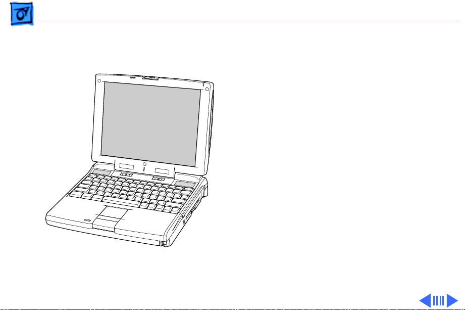
The PowerBook 3400
®
computers are all-in-one
notebooks with several
features that greatly
increase the performance of
PowerBooks. Its 603ev
microprocessor runs at a
clock frequency of either
180 or 200 MHz. In addition
to the 256 KB L2 cache, the
PowerBook 3400 comes
with 16 MB of RAM and is
upgradeable to 144 MB.
Page 5

Basics Product Overview - 2
The system includes a 1 GB or 2 GB hard drive, optional 6x
CD-ROM drive, and standard 1.44 MB floppy drive. And,
with its 12.1" display, the screen is larger than previous
PowerBook displays.
Page 6

Basics System Configurations - 3
System Configurations
The PowerBook 3400 comes in these configurations:
PowerBook 3400c/180 (February ‘97)
• Processor: 180 MHz PowerPC 603ev
• RAM: 16 MB
• Drives: 1 GB hard drive; 1.44 floppy drive; optional 6x
CD-ROM drive
• Display: 12.1-inch SVGA
PowerBook 3400c/200 (February ‘97)
• Processor: 200 MHz PowerPC 603ev
• RAM: 16 MB
• Drives: 2 GB hard drive; 1.44 floppy drive; 6x CD-ROM
drive
• Display: 12.1-inch SVGA
• Modem: EtherNet/modem card
Page 7

Basics System Configurations - 4
PowerBook 3400c/240 (March ‘97)
• Processor: 240 MHz PowerPC 603ev
• RAM: 16 MB
• Drives: 3 GB hard drive; 1.44 floppy drive; 12x CDROM drive
• Display: 12.1-inch SVGA
• Modem: EtherNet/modem card
Page 8
Basics View of Front and Right Side - 5
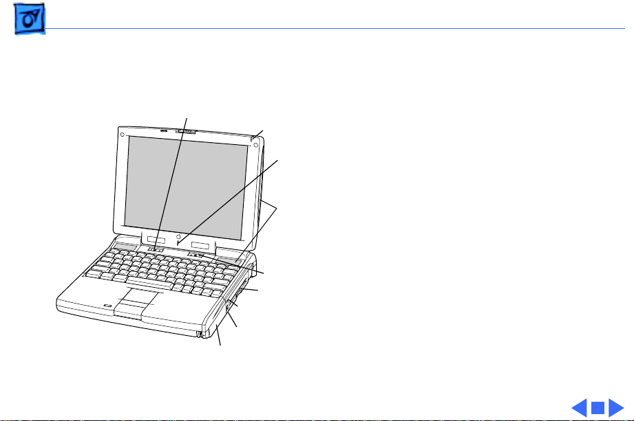
View of Front and Right Side
Volume Control
Sleep Indicator
®
Microphone
Stereo Speakers
Brightness Control
Floppy Drive
Expansion Bay Drive Light
Security Slot
Battery
The front of the computer
includes the following:
stereo speakers, volume
control, brightness control,
sleep indicator, and
microphone.
The right side includes the
battery, security slot,
expansion bay drive light,
and floppy drive.
Page 9
Basics View of Rear and Left Side - 6
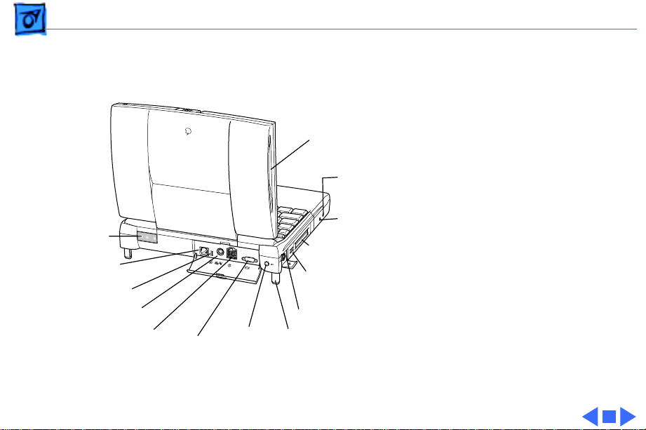
View of Rear and Left Side
Infrared
Window
Expansion
Port
Reset Button
Printer/External
Modem Port
SCSI Port (HDI-30)
Video Port
Power
Adapter
Port
Stereo Speaker
Two PCMCIA
card slots
PC Card
Eject Buttons
ADB Port
Elevation
Feet
Sound
Input
Port
Sound
Output
Port
The rear panel includes the
infrared window, reset
button, and these ports:
expansion, printer/external
modem, SCSI, video, and
power adapter.
The left side includes a
stereo speaker, two PC card
(PCMCIA) slots, PC card
eject buttons, and these
ports: sound input, sound
output, and ADB.
Page 10
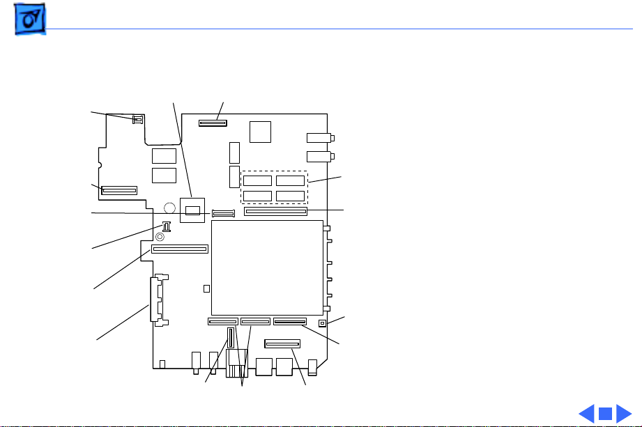
Basics Logic Board - 7
Fan
Connector
Power
Supply
Connector
Trackpad
Connector
LED
Connector
Ethernet/
Modem Board
Connector
CD-ROM or
Floppy Drive
Connector
(Front of 3400)
603e Microprocessor
Infrared
Connector
Hard Drive Connector
PCMCIA
Mechanism
Keyboard
Connectors
Display
Connector
16MB
Onboard
RAM
RAM Card
Connector
PCMCIA
Connector
Brightness &
Speaker
Connector
Logic Board
The logic board includes 16
MB of onboard RAM, the
PCMCIA mechanism, and
numerous connectors.
Page 11

Basics Cable Matrix - 8
Cable Matrix
For a matrix of cables that work with specific models of the
PowerBook family of computers, select the PowerBook Cable
Matrix located in Hardware/Compatibility Charts.
Page 12

Basics Battery Information - 9
Battery Information
Warning:
(LiIon)battery supplied with the PowerBook 3400, or an
identical model. Batteries designed for other portable
computers may look similar, but they may not work with
your computer and may damage it.
The LiIon and nickel-metal-hydride (NiMH) batteries look
similar. To distinguish them,
For the main battery, use only the lithium-ion
• Read the label on the battery, which will identify the
battery as either “LiIon” or “NiMH.”
• Look for battery indicator lights; if the battery has
them, it’s a LiIon battery.
Page 13
Basics Battery Information - 10
Main Battery
For its main battery the
PowerBook 3400 computers
use a lithium ion (LiIon)
battery. Each battery
provides power for up to
four hours of work time,
depending on the system
configuration and battery
conservation features
employed.
Note
: Although this battery
fits into a PowerBook 190/
5300, the PowerBook 190/
5300 will not recognize or
charge it.
Page 14

Basics Battery Information - 11
Optional Battery
The PowerBook 3400 can also use a nickel-metal-hydride
(NiMH) battery. This battery provides somewhat less work
time; the precise amount of work time depends on the model
you have and the battery conservation features you use.
Battery Handling Guidelines
The following are guidelines for properly handling the
PowerBook 3400 batteries:
Warning:
should not be thrown out with household or office trash. Take
dead batteries to an Apple authorized service provider for
recycling or proper disposal. Review battery handling and
disposal instructions in Safety Information in Bulletins/
Safety.
LiIon batteries contain hazardous chemicals and
Page 15

Basics Battery Information - 12
• Handle the battery carefully. Do not drop, puncture,
disassemble, mutilate, or incinerate it.
• Do not leave a battery in the computer for longer than a
week without plugging in the power adapter.
• Always put the battery cap on the battery when the
battery is out of the PowerBook. The battery contacts
should not be exposed when the battery is out of the
computer.
• Do not leave the battery in hot locations (such as the
trunk of a car).
• Do not leave a battery in storage for longer than six
months without recharging it.
• Never get batteries wet.
• Do not short-circuit the battery terminals. Doing so may
cause an explosion or a fire.
• Recharge batteries only as described in the user’s
manual and only in ventilated areas.
Page 16

Basics Battery Information - 13
Battery Matrix
For a matrix of batteries that work with specific models of
the PowerBook family of computers, select the PowerBook
Battery Matrix located in Hardware/Compatibility Charts.
Page 17
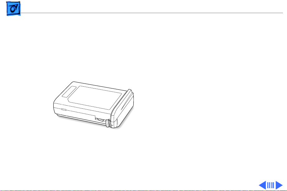
Basics PC Card Handling - 14
PC Card Handling
Two PC Card slots (also
known as PCMCIA slots) are
featured in the PowerBook
3400. The two slots accept a
variety of third-party PC
Cards with 68-pin
connectors.
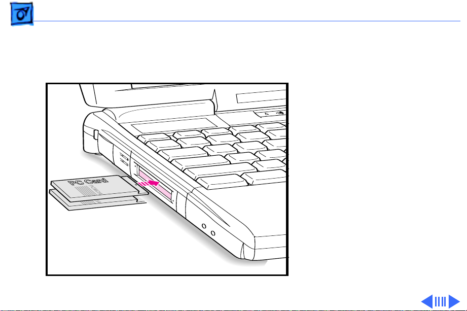
There are three types of PC
Cards: Type I (3.3 mm),
Type II (5 mm), and Type III
(10.5 mm). Type I and Type
II cards fit in either the
upper or lower slot of the PC
Card unit. Type III cards can
only be placed in the lower
Page 18

Basics PC Card Handling - 15
slot. When a Type III card is in the lower slot, the upper slot
cannot be used.
The following are guidelines for properly handling PC Cards:
• Use only cards that are compatible with the PC Card unit.
Refer to the compatibility information that came with the
card. If you cannot find the compatibility information,
call the card vendor.
• Do not insert anything other than a PC Card into the card
slots.
• The computer must be on or off in order to eject a PC
Card. When the computer is in sleep mode, a PC Card
cannot be ejected.
• Before you eject a card, make sure nothing is blocking
the card’s slot.
• If you want to use the card again immediately, pull it out
about an inch more and then push it back in. If you don’t
Page 19

Basics PC Card Handling - 16
follow this procedure and try to push the card back in to
use it again, the card will not engage properly.
• Do not pull on a PC Card before it has been ejected out of
the slot. Forcing a PC Card out of the slot may damage the
computer or the card.
Page 20

K
Service Source
Specifications
PowerBook 3400
Page 21

Specifications Processor - 1
Processor
CPU
Cache
PowerPC 603e microprocessor running at 180, 200, or 240
MHz
256 KB, second-level (L2) cache
Page 22

Specifications Memory - 2
Memory
RAM
ROM
16 of low-power DRAM
Customer-upgradeable
Expandable to 144 MB using TSOP low-profile RAM chips rated at
60 ns access time or faster
4 MB ROM
Page 23

Specifications Disk Storage - 3
Disk Storage
Floppy Drive
Hard Drives
CD-ROM Drives
Removable 1.44 MB floppy drive (in the expansion bay). Reads
and writes Macintosh 1.4 MB and 800K floppy disks, as well as
Windows, DOS, and OS/2 720K and 1.44 MB floppy disks.
1.3, 2.0, or 3 GB 2.5" hard drive
Optional, removable 6x-speed CD-ROM drive in the expansion
bay, if included (PowerBook 3400c/180; PowerBook 3400c/
200)
Removable 12x-speed CD-ROM drive in the expansion bay
(PowerBook 3400c/240)
Page 24

Specifications I/O Interfaces - 4
I/O Interfaces
SCSI
PC Cards
ADB
SCSI port (HDI-30 connector) for hard drives, scanners,
printers, and other devices; also supports PowerBook SCSI
disk mode
Two PC Card (PCMCIA card) slots support either two Type I or
Type II cards or one Type III card
Lower slot also supports “zoom video,” a method of displaying
video signals from a PC card
Apple Desktop Bus (ADB) port for keyboard, mouse, or other
input devices using a low-speed, synchronous serial bus
200 mA maximum current draw for all ADB devices
Supports up to three ADB devices in a daisy chain
Page 25

Specifications I/O Interfaces - 5
Serial
Sound
Infrared
Serial port for printer, modem (including Geo Port support),
LocalTalk network, or other serial devices (RS-422)
Sound output port for external audio amplifier/powered speakers,
stereo mini-jack, 3-connector, standard 3.5-mm stereo
miniplug; sound input port for stereo sound input (line level),
stereo mini-jack, 3-connector, standard 3.5-mm stereo
miniplug
16-bit stereo sound in and out supports 44.1 kHz (“CD quality”
sound), 22 kHz, and 11 kHz sample rates
Four built-in speakers; two housed in the display and two at the
top of the keyboard
Built-in infrared that supports two types of transmission—230
kilobit-per-second IRTalk and 1 megabit-per-second IrDA
Page 26

Specifications I/O Interfaces - 6
Power Adapter
Video
Security
Power adapter port
Video port for up to 16-bit/thousands-of-color video output to
most Apple monitors (with the supplied adapter), VGA
monitors (640 x 480), and SVGA monitors (800 x 600, 1024
x 768)
Connector on side panel allows users to attach security device;
also secures battery and any module in expansion bay
Page 27

Specifications Expansion Interfaces - 7
Expansion Interfaces
Expansion Bay
Expansion bay accepts a removable expansion bay module (floppy
drive, CD-ROM drive) or other modules
Page 28

Specifications I/O Devices - 8
I/O Devices
Keyboard
Trackpad
Microphone
Built-in keyboard with 12 function keys
76 keys domestic, 77 keys ISO
3.0-mm travel keyboard
19-mm vertical and horizontal pitch
Integrated, solid-state trackpad
Internal, electret, omnidirectional microphone
Page 29

Specifications Video - 9
Video
Macintosh
PowerBook 3400c
Video Display
12.1" diagonal, 800 x 600 active matrix (SVGA); thousands of
colors
Page 30

Specifications Electrical - 10
Electrical
Main Battery
Power Adapter
Backup Battery
Rechargeable lithium ion (LiIon) battery
2-4 hours of use before recharging
Input: 100-240 VAC line voltage, 50-60 Hz
Output: 24 V DC, 1.875 V nominally
45 W
60 milliampere (mAh) rechargeable NiMH battery for calendar/
clock maintenance. Also backs up contents of RAM for a few
minutes while battery is changed (when PowerBook is in sleep
mode)
Page 31

Specifications Electrical - 11
CD-ROM
Laser wavelength: 780 nanometers (nm)
Laser output: 0.6 milliwatts (mW)
Laser beam divergence: 53.4°±1
Page 32

Specifications Physical - 12
Physical
Dimensions
Weight
Height: 2.4 in. (6.56 mm)
Width: 11.5 in. (293 mm)
Depth: 9.5 in (239.5 mm)
7.2 lb. (3.2 kg) with floppy drive installed
7.4 lb. (3.3 kg) with CD-ROM drive installed
Page 33

Specifications Environmental - 13
Environmental
Operating
Temperature
Storage
Temperature
Relative Humidity
Operating Altitude
Shipping/NonOperating Altitude
50° to 104° F (10° to 40° C)
-13° to 140° F (-25° to 60° C)
20% to 80% noncondensing
10,000 ft. (3,048 m) maximum
15,000 ft. (4,572 m) maximum
Page 34

Specifications Environmental - 14
Environmental
Operating Temperature
Storage Temperature
Relative Humidity
Operating Altitude
Shipping/NonOperating Altitude
50° to 104° F (10° to 40° C)
-13° to 140° F (-25° to 60° C)
20% to 80% noncondensing
10,000 ft. (3,048 m) maximum
15,000 ft. (4,572 m) maximum
Page 35

K
Service Source
Troubleshooting
PowerBook 3400c
Page 36

Troubleshooting General - 1
General
In each product manual on Service Source, you will find
Flowcharts and/or Symptom Charts designed to help you
diagnose and repair Apple computers.
If you have narrowed the problem down to a particular
symptom, start with the Symptom Charts. Because cures are
listed in the order of most likely solution, try the first cure
first. Verify whether or not the product continues to exhibit
the symptom. If the symptom persists, try the next cure.
If you are not sure what the problem is, or if the Symptom
Charts do not resolve the problem, refer to the Flowcharts.
If you require additional assistance, contact Apple Technical
Support. Refer to the About topic under the Do menu for the
Apple Technical Support phone number.
Page 37

Troubleshooting Symptom Charts/Startup - 2
Symptom Charts
Startup
RAM failure occurs
(eight-tone error
chord sequence
sounds after startup
chord)
1 Remove RAM card (if present) and restart computer. If
startup sequence is normal, replace RAM card and retest.
2 Reseat RAM card and check connection.
3 Replace RAM card.
4 Replace logic board.
Page 38

Troubleshooting Symptom Charts/Startup - 3
Hardware failure
occurs (four-tone
error chord sequence
sounds after startup
chord)
Startup failure
occurs when using
minimum System
Folder and System
7.6.
1 Reset PRAM.
2 Remove floppy drive from media bay and restart computer.
If startup sequence is normal, insert floppy drive and retest.
3 Replace floppy mechanism.
4 Disconnect hard drive cable and restart computer. If startup
sequence is normal, reconnect cable and retest.
5 Replace hard drive.
6 Replace logic board.
Upgrade to System Enabler 1.2.1 or later. Refer to Apple Software
Updates on Service Source Companion CD.
Page 39

Troubleshooting Symptom Charts/Power - 4
Power
Note:
You will hear only the click of the power-on button when
you attempt to start up a computer that lacks sufficient power to
start.
Computer won’t
power up
1 If sleep LED is continually on, backup battery power has
been interrupted. Restart computer by holding down reset
actuator 10-20 seconds. If computer doesn’t restart, repeat
3–4 times.
2 Try known-good power adapter.
3 Try known-good, charged battery.
4 Connect power adapter and restart computer in 3–4 minutes.
5 Replace power supply board.
6 Replace logic board.
Page 40

Troubleshooting Symptom Charts/Power - 5
Screen is blank;
computer doesn’t
respond
1 If sleep LED is continually on, backup battery power has
been interrupted. Restart computer by holding down reset
actuator 10-20 seconds. If computer doesn’t restart, repeat
3–4 times.
2 Restart computer.
3 Disconnect power adapter, remove battery, and restart
computer in 3-4 minutes.
4 Check power adapter cable.
5 Try known–good, charged battery.
6 Try known-good power adapter.
7 Reset power manager.
8 Check all logic board cables and connections.
9 Replace keyboard.
10 Replace power supply board.
11 Replace logic board.
Page 41

Troubleshooting Symptom Charts/Power - 6
After you remove
battery, some
Control Panel
settings are different
Computer runs when
plugged into wall
outlet but not on
battery power;
battery voltage is
within tolerance
1 Check keyboard and backup battery cables and connections.
2 Replace backup battery.
3 Replace logic board.
1 Reset power manager.
2 Reseat battery to make sure battery is mating with contacts
on logic board.
3 Try known-good battery.
4 Try known-good power adapter.
5 Replace power supply board.
6 Replace logic board.
Page 42

Troubleshooting Symptom Charts/Power - 7
Power adapter is
plugged in, but
Control Strip doesn’t
indicate adapter is
connected
When Shutdown is
selected with power
adapter plugged in,
computer shuts down
but immediately
powers back up
1 Verify that power adapter is connected correctly.
2 Try known-good power adapter.
3 Replace logic board.
1 Reset PRAM.
2 Disconnect power adapter, remove battery, disconnect
backup battery, and wait 15 minutes before retesting.
Page 43

Troubleshooting Symptom Charts/Power - 8
Low-power warning
appears
1 Attach power adapter and recharge battery.
2 Disconnect peripherals. If warning disappears when
peripherals are disconnected, verify that peripherals are
low-power.
3 Reduce use of CD-ROM, floppy, or hard drive; sound;
backlight; or other power-consuming devices. Or, reconnect
power adapter.
4 Try known-good, charged battery.
5 Try known-good power adapter.
6 Inspect power adapter port: Verify that connector is not
loose; if it is, replace main logic board.
7 Replace power supply board.
8 Replace logic board.
Page 44

Troubleshooting Symptom Charts/Video - 9
Video
Note:
A certain number of defects are inherent in display
technology and vary by many factors, including type of technology.
If you suspect that your display contains an abnormal number of
defects, call Apple Technical Support.
Partial or full row of
pixels is always on or
never comes on in an
active matrix display
1 Check display and backlight cables and connections.
2 If display cable connection to logic board is loose, replace
brightness and speaker grill.
3 Replace display.
4 Replace logic board.
Page 45

Troubleshooting Symptom Charts/Video - 10
Display is very light
or totally white
Display stopped
working or dimmed
but is fine now
1 Adjust screen contrast and brightness settings.
2 Verify display cable, inverter board, and logic board
connections.
3 If display cable connection to logic board is loose, replace
brightness and speaker grill.
4 Replace inverter board.
5 Replace display.
6 Replace logic board.
1 Replace display.
Page 46

Troubleshooting Symptom Charts/Video - 11
Backlight doesn’t
operate
1 Adjust screen brightness setting.
2 Verify that backlight cable connection is secure.
3 Check display cable, inverter board, and logic board
connections.
4 If display cable connection to logic board is loose, replace
brightness and speaker grill.
5 Verify that cables are not pinched or severed.
6 Replace inverter board.
7 Replace display.
8 Replace logic board.
Ê
Page 47

Troubleshooting Symptom Charts/Video - 12
No display, but
computer appears to
operate correctly
Note:
If sleep light is blinking and computer is not in sleep mode,
reset power manager.
1 Insert disk into floppy drive and press Command–e (eject
disk) to verify that computer is working.
2 Adjust screen brightness setting.
3 Verify display cable, inverter board, trackpad, keyboard,
and logic board connections.
4 If display cable connection to logic board is loose, replace
brightness and speaker grill.
5 Connect power adapter.
6 Replace inverter board.
7 Replace display.
8 Replace logic board.
Page 48

Troubleshooting Symptom Charts/Video - 13
Thin white line is
always on at middle of
screen
An external monitor
connected to the
PowerBook shows no
video
An external monitor
connected to the
PowerBook shows
either horizontal or
vertical rolling, or
horizontal or
vertical distortion
1 Change the desktop pattern; if the line remains, replace
display.
1 Verify cable and cable connections between monitor and video
board.
1 Verify monitor using another computer.
2 Replace logic board.
Page 49

Troubleshooting Symptom Charts/Sound - 14
Sound
No sound from
speaker(s)
1 Verify that volume setting in Control Panel is above 0.
2 Verify that no external speaker is plugged in.
3 Check display cable connections.
4 Check inverter board connections.
5 Replace display cable.
6 Replace inverter board.
7 Replace speaker(s).
8 Replace logic board
.
Page 50

Troubleshooting Symptom Charts/Floppy Drive - 15
Floppy Drive
Note:
The floppy drive cable referred to in this section is the
cable
inside
of the floppy drive case.
Audio and video
present, but floppy
drive in media bay
does not operate
1 Try known-good floppy disk.
2 Check floppy drive cable connection.
3 Replace floppy drive cable.
4 Replace floppy drive.
5 Replace logic board.Ê
Page 51

Troubleshooting Symptom Charts/Floppy Drive - 16
Disk ejects while
booting; display
shows Mac icon with
blinking X
1 Try known-good system disk.
2 Verify that floppy disk is not locked.
3 Verify that trackpad and trackpad button are working.
4 Verify that keyboard is working.
5 Check floppy drive cable connection.
6 Replace floppy drive cable.
7 Replace floppy drive.
8 Replace logic board.
Page 52

Troubleshooting Symptom Charts/Floppy Drive - 17
Disk does not eject 1 Switch off system and hold trackpad button down while you
switch system on.
2 Eject disk manually by carefully inserting opened paper clip
into hole near floppy drive slot.
3 Check floppy drive cable connection.
4 Replace floppy drive cable.
5 Replace floppy drive.
6 Replace logic board.
Disk initialization
fails
1 Try known-good floppy disk.
2 Check floppy drive cable connection.
3 Replace floppy drive cable.
4 Replace floppy drive.
5 Replace logic board.
Ê
Page 53

Troubleshooting Symptom Charts/Floppy Drive - 18
Read/write/copy
error
1 Try known-good floppy disk.
2 Check floppy drive cable connection.
3 Try to format a floppy disk.
4 Replace floppy drive cable.
5 Replace floppy drive.
6 Replace logic board.
Page 54

Troubleshooting Symptom Charts/Hard Drive - 19
Hard Drive
Internal hard drive
does not spin up
1 Make sure power adapter is connected.
2 Disconnect external SCSI devices.
3 Check hard drive cable connection.
4 Replace hard drive cable.
5 Use Hard Drive Format to reinitialize drive.
6 Replace hard drive.
7 Replace logic board.
Page 55

Troubleshooting Symptom Charts/CD-ROM Drive - 20
CD-ROM Drive
CD-ROM drive does
not accept disc
Volume control does
not operate correctly
Macintosh cannot
mount CD-ROM drive
1 Replace disc (if dirty or damaged).
2 Reinsert CD-ROM drive.
3 Replace CD-ROM drive.
1 Check Control Panel Sound setting.
2 Reinsert CD-ROM drive.
1 Reinsert CD-ROM drive.
2 Replace CD-ROM drive.
Page 56

Troubleshooting Symptom Charts/CD-ROM Drive - 21
Audio and video
present, but CD-ROM
drive in media bay
does not operate
1 Try known-good CD-ROM disc.
2 Check CD-ROM drive cable connections (inside CD-ROM
case).
3 Replace CD-ROM drive cable.
4 Replace CD-ROM drive.
Page 57

Troubleshooting Symptom Charts/PC Card Module (PCMCIA) - 22
PC Card Module (PCMCIA)
PC Card won’t eject 1 Make sure computer is not in sleep mode.
2 Make sure PC Card slot is not blocked.
3 Insert straightened paper clip into hole next to slot.
4 Use needlenose pliers to remove PC Card.
5 Verify that PC Card is not warped or damaged in any way; if
so, replace with new card.
PC Card is inserted
but doesn’t appear on
desktop
Note:
Modem and communication cards may not appear on desktop.
1 Try PC Card in the other slot.
2 Replace PC Card.
3 Replace PC Card cage.
4 Replace logic board.
Page 58

Troubleshooting Symptom Charts/PC Card Module (PCMCIA) - 23
Note:
If “defective card” or “unrecognizable card” appears in
place of card name in PCMCIA Eject control panel, card is
damaged or computer does not have software required to support
it. Eject card.
System with PC card
performs poorly or
hangs during floppy
drive operations
Replace logic board.
Page 59

Troubleshooting Symptom Charts/Infrared Communication - 24
Infrared Communication
Infrared
communication is not
working
1 Clean infrared window with soft lint-free cloth.
2 Verify infrared cable connection.
3 Verify infrared signal is being received by host computer.
4 Replace infrared cable.
5 Replace infrared board.
Page 60

Troubleshooting Symptom Charts/Peripherals - 25
Peripherals
After you connect
external SCSI device,
computer does not
boot
1 Verify that device and SCSI chain are terminated correctly.
2 Switch on external SCSI device before starting computer.
3 Check cable connections.
4 Try known-good SCSI cable.
5 Verify that SCSI ID select switch setting on external device is
unique.
6 Try known-good external SCSI device.
7 Replace logic board.
Ê
Page 61

Troubleshooting Symptom Charts/Peripherals - 26
Cursor does not move
when you are using
trackpad
1 Shut down computer, unplug adapter, and remove battery.
Let computer sit for 1 minute before restarting.
2 Reset power manager.
3 Check trackpad connections.
4 Check keyboard and logic board connections.
5 Connect low-power mouse and try to move cursor. If cursor
moves, try using trackpad and keyboard. If trackpad does not
move cursor, replace trackpad. If keyboard does not respond,
replace keyboard.
6 Replace logic board.
Page 62

Troubleshooting Symptom Charts/Peripherals - 27
Cursor intermittently
does not move or
moves erratically
Note:
User must touch trackpad with the surface of only one
finger at a time and point directly down on the trackpad surface.
1 Clean trackpad surface (with computer off, using a non-
static inducing material).
2 Check trackpad connections.
3 Replace trackpad.
4 Replace keyboard.
5 Replace logic board.
Page 63

Troubleshooting Symptom Charts/Peripherals - 28
Cursor moves, but
clicking trackpad
button has no effect
1 Reset power manager.
2 Check trackpad connections.
3 Check keyboard and logic board connections.
4 Replace trackpad cable.
5 Replace trackpad.
6 Replace keyboard.
7 Replace logic board.
Page 64

Troubleshooting Symptom Charts/Peripherals - 29
Cursor does not move
when you are using
mouse
No response to any
key on keyboard
1 Check mouse connection to ADB port.
2 Try a known-good low-power mouse. If the known-good
mouse works, clean mouse ball and inside of original mouse
and retest. If the original mouse still doesn’t work, replace
it.
3 Replace logic board.
1 Verify that computer is on.
2 Reset the power manager.
3 Check keyboard connection by disconnecting and reconnecting
keyboard cables.
4 Replace keyboard.
5 Replace logic board.
Ê
Page 65

Troubleshooting Symptom Charts/Peripherals - 30
Known-good directconnect printer does
not print
Known-good network
printer does not print
1 Reset PRAM.
2 Verify that Chooser and Control Panel settings are correct.
3 Check cables.
4 Replace printer cable.
5 Try known-good printer.
6 Replace logic board.
1 Reset PRAM.
2 Verify that Chooser and Control Panel settings are correct.
3 Check cables.
4 Attach computer directly to printer, and retest.
5 Replace logic board.
Ê
Page 66

Troubleshooting Symptom Charts/Peripherals - 31
I/O devices are
unrecognized, or
garbage is
transmitted or
received
In disk mode,
computer does not
display SCSI icon
until host is booted,
or computer crashes
when host is shut
down
1 Reset PRAM.
2 Check cables.
3 Verify that SCSI device is correctly terminated.
4 Verify that SCSI select switch setting on external device is
unique.
5 Test device with known-good computer.
6 Replace logic board.
1 Verify that computer has a unique SCSI ID.
2 Check that SCSI disk mode cable is good and that connection is
tight.
3 Replace logic board.
Page 67

Troubleshooting Symptom Charts/Miscellaneous - 32
Miscellaneous
Sleep light won’t
come on
Screen goes blank and
computer shuts down
every few minutes
Application seems to
run slower after a few
seconds
Hard drive is slow to
respond, or screen
goes blank too often
1 Verify that computer is in sleep mode and not powered off.
2 Reset power manager.
3 Replace inverter board.
Computer is going into system sleep to conserve battery power.
Adjust sleep delays in Control Panel or connect power adapter.
Computer is switching to system rest. If system rest is
interfering with operation of application, connect power
adapter.Ê
Adjust sleep delays in Control Panel or connect power adapter.
Ê
Page 68

Flowcharts Troubleshooting - 33
Troubleshooting Flowchart—Startup Problems
START
Reset the
Power Manager.
Press power button to
begin boot sequence.
Do you
hear the
startup
tones?
Yes
Are the
startup tones
normal?
Yes
Does a
gray screen
appear with
pointer?
Yes
1
No
No
No
Does any
video
appear?
Yes
1. Check the volume.
2. Check the keyboard and
display cables.
3. Replace the speaker.
4. Replace the logic board.
See "Startup" in the
Symptom Charts.
1. Check display/inverter cable
connections.
2. Replace the display and
backlight cables.
3. Replace the inverter.
4. Replace the display.
5. Replace the logic board.
1. Check the keyboard and
No
display cables.
2. Replace the keyboard.
3. Replace the logic board.
Page 69

Flowcharts Troubleshooting - 34
Troubleshooting Flowchart—Startup Problems
1
Does
the
PowerBook continue
to boot to the
desktop?
Yes
Do the
trackpad and
keyboard
function?
Yes
Insert a known-good disk
into the floppy disk drive
and try to initialize it.
No
No
Does
the flashing
question mark
appear?
Yes
1. Reset PRAM.
2. Boot from Disk Tools.
3. If hard drive appears, reinstall system software.
4. If hard drive doesn't appear,see if Hard Drive
Format can reformat it.
5. Replace the hard drive cable.
6. Replace the hard drive.
7. Replace the logic board.
1. Reset PRAM.
2. Check the trackpad and
keyboard cables.
3. Replace the trackpad and
keyboard cables.
4. Replace the trackpad.
5. Replace the keyboard.
6. Replace the logic board.
1. Boot with extensions off.
2. Boot with Disk Tools
No
Update Driver.
3. Replace the hard drive.
4. Replace the logic board.
Go to
Start
Does the
disk
initialize?
Yes
END
No
1. Replace the floppy drive cable.
2. Replace the floppy drive.
Page 70

K
Service Source
T ak e Apart
PowerBook 3400c
Page 71

Take Apart Tools - 1
Tools
Use the following tools for taking apart these computers:
• Small, flat-blade screwdriver
• #8 Torx driver (for removing most screws)
• #6 Torx driver (for removing the floppy drive screws)
• Swizzle stick (for removing name plates and kapton tape)
• Dental pick (for opening flex connectors)
Page 72

Take Apart Screws - 2
Screws
There are 38 screws installed in this PowerBook (not
including the CD-ROM drive) in 12 different sizes.
You will notice that each part other than the floppy drive
case kit uses only one type of screw, which makes
reassembly easier than in other PowerBooks. For example,
the display frame uses 6 identical screws and the trackpad
button uses 2 identical screws.
For the location of each screw in the PowerBook 3400c,
refer to the Exploded View chapter.
Page 73

Take Apart Bottom Case Assembly - 3
Bottom Case Assembly
Procedures for removing parts from the bottom case
assembly are detailed on the following pages.
Page 74

Take Apart Battery - 4
Battery
Before you begin, unplug the
power adapter
Caution:
the battery before
performing any take-apart
procedure.
You must remove
Page 75

Take Apart Battery - 5
1 Push the button and slide
the battery out of the
media bay.
Replacement Caution:
must install the battery
before connecting the power
adapter.
You
Page 76

Take Apart Floppy Drive Assembly - 6
Floppy Drive Assembly
No preliminary steps are
required
Note
: Media bay devices
require approximately 7 lb.
pull strength.
Page 77

Take Apart Floppy Drive Assembly - 7
Caution:
assembly without damaging
it, turn the unit upside
down, as shown.
1 Slide the release button
Caution
area of the plastics—
metal cover. This prevents
bending the metal top case
and possibly damaging the
drive.
2 Grasp the floppy drive
To remove the
forward.
: Grasp the ridged
not
the
assembly by its ridged
area and pull it out of the
media bay.
Page 78

Take Apart Floppy Drive Assembly - 8
Replacement Caution:
media bay devices carefully before inserting them into the
bay.
Media bay tolerances are tight. Align
Page 79

Take Apart CD-ROM Drive Assembly - 9
CD-ROM Drive Assembly
No preliminary steps are
required.
Note
: Media bay devices
require approximately 7 lb.
pull strength.
Page 80

Take Apart CD-ROM Drive Assembly - 10
Caution:
assembly without damaging
it, turn the unit upside
down, as shown.
1 Slide the release button
Caution
area of the plastics—
metal cover. This prevents
bending the metal top case
and possibly damaging the
drive.
2 Grasp the CD-ROM
To remove the
forward.
: Grasp the ridged
not
the
drive assembly by its
ridged area and pull it
out of the media bay.
Page 81

Take Apart CD-ROM Drive Assembly - 11
Replacement Caution:
media bay devices carefully before inserting them into the
bay.
Media bay tolerances are tight. Align
Page 82

Take Apart Keyboard - 12
Keyboard
Before you begin, remove
the following:
• Battery
• Floppy or CD-ROM Drive
Assembly
Page 83

Take Apart Keyboard - 13
1 Close the computer and
turn it upside down.
2 Remove the 3
interchangeable screws
from the bottom case.
Page 84

Take Apart Keyboard - 14
3 Open the computer.
Caution:
keyboard too far, you will
rip the keyboard cables out
of their connectors. Pull the
keyboard just enough so its
4 interior tabs clear the
brightness & speaker grill.
4 Inserting a flat-blade
If you pull the
screwdriver under the
front of the keyboard,
lift the keyboard slightly
up and toward you until
you feel a slight
resistance.
Page 85

Take Apart Keyboard - 15
5 Gently turn the keyboard
onto the palm rest.
Caution:
the backup battery wires,
gently pull them out of their
2 catches on the PCMCIA
insulator. Then move them
to the side so they clear the
right-hand keyboard
connector.
6 Using a dental pick,
To avoid damaging
detach the keyboard
cables from their
connectors.
Page 86

Take Apart Keyboard - 16
7 If a foam gasket is not
already installed on the
bottom of the keyboard,
install a gasket (part
number 922-3103) as
illustrated.
Replacement Note
replace each keyboard
screw, apply pressure to the
area of the keyboard
immediately behind each
screw hole. This allows the
screws to install more
easily.
: As you
Page 87

Take Apart RAM Card - 17
RAM Card
Before you begin, remove
the following:
• Battery
• Floppy Drive
• Keyboard
Page 88

Take Apart RAM Card - 18
Grasp the RAM card by the
corners closest to you—
RAM Card
supporting the bottom left
corner over the connector—
and lift straight up.
Page 89

Take Apart Brightness & Speaker Grill - 19
Brightness & Speaker Grill
Before you begin, remove
the following:
• Battery
• Floppy or CD-ROM Drive
Assembly
• Keyboard
Note
: If you are not
performing an additional
take-apart, it is not
necessary to detach the
cables of the keyboard.
Page 90

Take Apart Brightness & Speaker Grill - 20
1 Using a dental pick,
detach the brightness &
speaker cable from its
connector.
2 Remove the screw from
the brightness & speaker
grill.
3 Lift off the brightness &
speaker grill.
Page 91

Take Apart Brightness & Speaker Grill - 21
4 Using your fingers,
disconnect the backup
battery connector.
Note:
The backup battery is
adhered to the grill with
reusable adhesive.
5 Gently pull the backup
battery off the grill.
Replacement Caution
Install the backup battery in
exactly the same location or
you will not be able to align
the grill.
:
Page 92

Take Apart Left & Right Clutch Covers - 22
Left & Right Clutch Covers
Before you begin, remove
the following:
• Battery
• Floppy or CD-ROM Drive
Assembly
• Keyboard
• Brightness & Speaker
Grill
Page 93

Take Apart Left & Right Clutch Covers - 23
1 Position the display
assembly at 170° from
the body of the computer.
2 Grasp the area of the
clutch cover under the
display. Using a
fingernail, pull up from
the seam in back and
gently rock the cover
until it releases.
3 Pull the cover straight
up, watching to clear
the bottom of the display
assembly.
Page 94

Take Apart Left & Right Clutch Covers - 24
Replacement Note
the right & left clutch covers. (The tabs on the palm rest fit
under the clutch cover tabs.)
: Install the palm rest before installing
Page 95

Take Apart Palm Rest - 25
Palm Rest
Before you begin, remove
the following:
• Battery
• Floppy or CD-ROM Drive
Assembly
• Keyboard
• Brightness & Speaker
Grill
• Left & Right Clutch
Covers
Caution
pull the trackpad cable out
of the connector as you turn
over the palm rest.
: Be careful not to
Page 96

Take Apart Palm Rest - 26
1 Grasp the right corner of
the palm rest and pull it
up.
2 Grasp the top ridge of the
palm rest and pull it up.
3 Turn the palm rest over
and set it in the area the
keyboard occupied.
Page 97

Take Apart Palm Rest - 27
4 Using a dental pick,
detach the trackpad
connector.
Replacement Notes:
• Before you connect the
trackpad cable to the
logic board, make sure
the ferrite bead is
installed.
• Install the palm rest
before installing the left
& right clutch covers.
(The palm rest tabs fit
under the clutch cover
tabs.)
Page 98

Take Apart Trackpad - 28
Trackpad
Before you begin, remove
the following:
• Battery
• Floppy or CD-ROM Drive
Assembly
• Keyboard
• Brightness & Speaker
Grill
• Left & Right Clutch
Covers
• Palm Rest
Page 99

Take Apart Trackpad - 29
1 Remove the 2
interchangeable screws
that hold the trackpad
button in place.
Page 100

Take Apart Trackpad - 30
2 Slide the switch board
out from the 4 tabs
holding it in place.
3 Disconnect the trackpad
cable from the trackpad
board.
4 Lift the trackpad board
out from under the
mounting ledge.
Replacement Note
2 tiny notches on the
trackpad (near the bottom)
and how they align with the
tabs in the plastics.
: Note the
 Loading...