

Page 1

K
Service Source
PowerBook 2300 Series
PowerBook Duo 2300c
Page 2

K
Service Source
Basics
PowerBook 2300 Series
Page 3
Basics General Information - 1
General Information
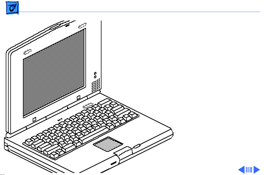
The PowerBook Duo 2300c
brings RISC- based
PowerPC processor
technology to the
subnotebook class. This
system features a 100megahertz PowerPC 603e
processor, an active-matrix
color display, and a
trackpad. Its integrated 9.5inch display offers two
modes—640 by 480 pixels
with 256 colors, or 640 by
400 pixels with up to
Page 4

Basics General Information - 2
thousands of colors. Also offered are a high-capacity hard
disk and RAM that can easily be expanded to 56 megabytes.
Page 5

Basics Repair Strategy - 3
Repair Strategy
Service the PowerBook 2300 Series computers through
module exchange and parts replacement. Customers can
request on-site service from an Apple Authorized Service
Provider Plus (AASP+) Apple Assurance (US only), or
request a courier through the Apple Canada Technical
Answerline (Canada only). They can also choose carry-in
service from an AASP.
Ordering
Apple Service Providers planning to support the computer
systems covered in this manual may purchase Service
modules and parts to develop servicing capability. To order
parts, use the AppleOrder (US only) or ARIS (Canada only)
system and refer to “Service Price Pages.”
Page 6

Basics Repair Strategy - 4
Large businesses, universities, and K-12 accounts must
provide a purchase order on all transactions, including
orders placed through the AppleOrder (US only) or ARIS
(Canada only) system.
USA Ordering
US Service Providers not enrolled in AppleOrder may fax
their orders to Service Provider Support (512-908-
8125) or mail them to
Apple Computer, Inc.
Service Provider Support
MS 212-SPS
Austin, TX 78714-9125
For US inquiries, please call Service Provider Support at
800-919-2775 and select option #1.
Page 7

Basics Repair Strategy - 5
Canadian Ordering
Canadian Service Providers not enrolled in ARIS may fax
their orders to Service Provider Support in Canada
(1-800-903-5284). For Canadian inquiries, please call
Service Provider Support at 905-513-5782 and select
option #3.
Page 8

Basics Warranty/AppleCare/ARIS - 6
Warranty/AppleCare/ARIS
US Only
The PowerBook 2300 Series computers are covered under
the Apple One-Year Limited Warranty. The AppleCare
Service Plan is also available for these products. Service
Providers are reimbursed for warranty and AppleCare
repairs made to these computers. For pricing information,
refer to “Service Price Pages.”
Canada Only
The PowerBook 2300 Series computers are covered under
first-year AppleCare. The Extended AppleCare Service Plan
is also available for these products. Service Providers are
reimbursed for first-year warranty and Extended
AppleCare repairs made to these computers. For pricing
information, refer to “Service Price Pages.”
Page 9

Basics Tools Required - 7
Tools Required
The following tools are required to disassemble a PowerBook
Duo 2300c system:
• T-6 torx driver
• T-8 torx driver
• T-10 torx driver
• IC extractor
• Jeweler’s flat-blade screwdriver
• # 00 Phillips screwdriver
• Duo battery contact alignment tool
Page 10
Basics Logic Board Connectors - 8
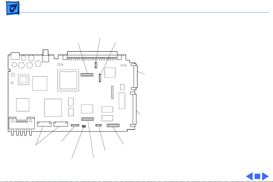
Logic Board
FSTN
Microphone
TFT
Connectors
Keyboard
PPC
603e
Sleep
Switch
Trackpad
Modem
RAM
Expansion
SCSI Hard Drive
Backup Battery
IDE Hard Drive
Page 11
Basics Rear Panel - 9
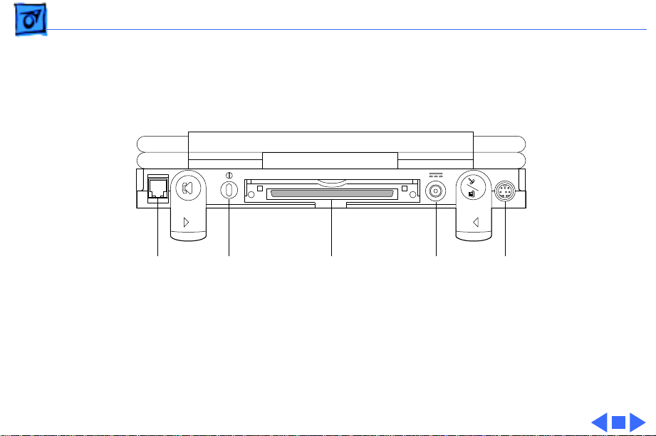
Rear Panel
Modem
Port
(internal)
Power
On
Docking
Connector
Power
Adapter
Serial
Port
Page 12
Basics Screw Matrix - 10
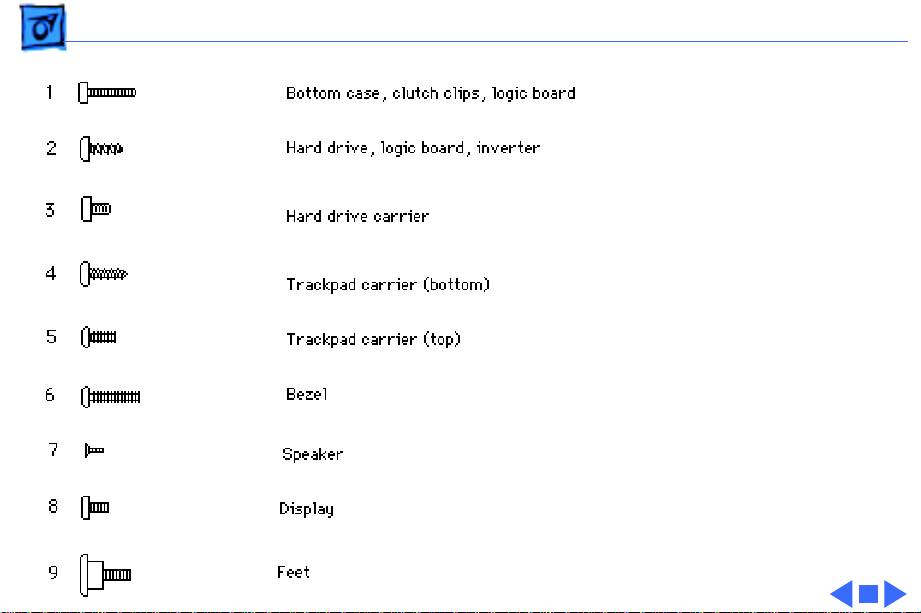
Screw Matrix
Nine different types of
screws are used in the
PowerBook Duo 2300c. Most
are Torx screws that
require a T-6 or T-8 Torx
screwdriver.
The following matrix
illustrates these screws and
notes their location in the
unit.
When installing the screws,
make them finger-tight; do
not overtighten.
Page 13

K
Service Source
Specifications
PowerBook 2300 Series
Page 14

Specifications Introduction - 1
Introduction
You can also find specifications information for this product in the
Spec Database, which you can access in one of three ways:
— Launch it directly by double-clicking the Apple Spec Database
runtime alias at the top level of the Main Service Source CD.
— Select "Apple Spec Database" from the Service Source drop-
down main menu.
— Click the Acrobat toolbar icon for the database, which is near
the right end of the toolbar with the letters "SP."
Page 15

Specifications Processor - 2
Processor
CPU
Addressing
PowerPC 603e RISC processor
100 MHz
32-bit data bus
Page 16

Specifications Memory - 3
Memory
RAM
ROM
Clock/Calendar
8 MB of low-power, self-refresh dynamic RAM on board
Expandable to 56 MB
Maximum of 48 MB RAM expansion card, with 70 ns or faster
chips
1 MB of ROM on board
CMOS custom chip with long-life rechargeable lithium battery
Page 17

Specifications Disk Storage - 4
Disk Storage
Hard Drive
Floppy Drive
Internal 2.5” IDE drive (750 MB or 1.1 GB)
Optional external 1.4 MB Apple SuperDrive
Page 18

Specifications I/O Interfaces - 5
I/O Interfaces
Processor-Direct Slot
Serial
Modem
Power Adapter
152-pin processor-direct slot (PDS) connector for attaching
expansion devices
32-bit expansion bus
Serial port for attaching modem, printer, AppleTalk network, or
other serial device (RS-422 or mini DIN-8)
Modem telephone jack (RJ-11 in United States, mini DIN-8
elsewhere) for optional internal modem
Power adapter port
Page 19

Specifications I/O Devices - 6
I/O Devices
Keyboard
Trackpad
Built-in standard Apple keyboard
63 keys, domestic; 64 keys, ISO
Caps-locked LED
Soft power-on switch
2.4 mm travel; 18 mm vertical and horizontal pitch
Two-level tilt adjustment using feet
Solid-state trackpad
400 dpi resolution for relative mode
520 dpi minimum resolution for absolute mode
Page 20

Specifications Sound and Video - 7
Sound and Video
Sound Generator
Microphone
Speaker
Video Display
4-voice sound with 8-bit digital-analog conversion
Records at 11 kHz or 22 kHz sample rate
Built-in, omnidirectional
Electret
Built-in
9.5” active-matrix color display
640 by 480 pixels with 256 colors, or 640 by 400 pixels with
thousands of colors
Page 21

Specifications Electrical - 8
Electrical
Main Battery
Power Adapter
Microphone
Apple Desktop Bus
(ADB)
NiMH (nickel metal hydride), Type 3
2-4 hours of use before recharging
Recharge time: approximately 2 hours if in sleep or shutdown
mode; approximately 4 hours when computer is in use
Input: AC 100-240 V, 50-60 Hz
Output: DC 24 V, 1.5 A, 36 W
Output: 4 mV peak to peak at normal speaking volume
Maximum current draw: 100 mA (PowerBook Duo MiniDock or
PowerBook Floppy Adapter) or 500 mA (PowerBook Duo Dock)
Page 22

Specifications Physical - 9
Physical
Dimensions
Weight
Height: 1.5 in. (3.8 cm)
Width: 10.9 in. (27.7 cm)
Depth: 8.5 in. (21.6 cm)
4.8 lb. (2.2 kg)
Page 23

Specifications Environmental - 10
Environmental
Operating
Temperature
Storage
Temperature
Relative Humidity
Operating Altitude
Storage Altitude
41–95° F (5–35° C) if used alone or connected to a MiniDock or
floppy disk adapter
41-86° F (5-30° C) if used in a Duo Dock Plus or other Duo Dock
-13° to 140° F (-25° to 60° C)
20% to 80% noncondensing
0–10,000 ft. (0–3,048 m) maximum
0–15,000 ft. (0–4,572 m) maximum
Page 24

Specifications Other - 11
Other
Express Modem
SCSI Adapter
14,400-bps data transmission, with 14,400-bps fax send and
receive capability
Supports two error-correction and data-compression protocols:
MNP classes 2 to 5 and CCITT standard V.42/V.42bis
Enables connection between PowerBook computer and desktop
Macintosh (PowerBook appears as a hard drive on the desktop)
Page 25

K
Service Source
Troubleshooting
PowerBook 2300 Series
Page 26

Troubleshooting General - 1
General
The Symptom Charts included in this chapter will help you
diagnose specific symptoms related to your product. Because cures
are listed on the charts in the order of most likely solution, try
the first cure first. Verify whether or not the product continues to
exhibit the symptom. If the symptom persists, try the next cure.
(Note: If you have replaced a module, reinstall the original module
before you proceed to the next cure.)
If you are not sure what the problem is, or if the Symptom Charts
do not resolve the problem, refer to the Flowchart for the product
family.
For additional assistance, contact Apple Technical Support.
Page 27

Troubleshooting Battery Contact Alignment - 2
Battery Contact Alignment
Use the Duo battery contact alignment tool in these situations:
• Any time a battery contact screw is loosened, removed, or
replaced.
• Whenever a PowerBook Duo logic board is installed or
reassembled into a system.
• Whenever a PowerBook Duo with a known good battery shuts
down unexpectedly (other than going to sleep), won’t boot off
the battery, or intermittently powers off when running off the
battery.
• Any time a known good PowerBook Duo battery won’t charge.
Page 28

Troubleshooting Power Manager Reset - 3
Power Manager Reset
If a unit crashes or experiences power problems, reset the power
manager chip by pressing the rear power switch for 30-45
seconds.
If resetting the power manager chip does not solve the problem,
reset the code for the power manager chip by removing all power
sources and letting the unit sit for 10 minutes. (Take out the
battery and disconnect the AC adapter and the internal backup
battery.) This forces the PowerBook Duo to reload the power
manager code from the system software.
Page 29

Troubleshooting Symptom Charts/Startup - 4
Symptom Charts
Startup
RAM failure occurs
(eight-tone error
chord sequence
sounds after startup
chord)
1 Attach power adapter.
2 Check RAM expansion card connection.
3 Replace RAM expansion card
4 Replace logic board.
Note:
When replacing the logic board, check that the serial port
EMI clip is attached to the bottom of the CPU stiffener. If it is
missing, replace the stiffener. On international units, also
replace the stiffener if the modem EMI clip is missing. The “CPU
Stiffener” topic in Take Apart helps you locate and identify the
two EMI clips.
Note:
Perform the battery contact alignment procedure when
you replace a logic board. (See Additional Procedures “Align
Battery Contacts.”)
Page 30

Troubleshooting Symptom Charts/Startup - 5
Hardware failure
occurs (four-tone
error chord sequence
sounds after startup
chord)
1 Check that mylar tape on docking connector is attached and in
place.
2 Disconnect hard drive cable from logic board and reboot
system. If startup sequence is normal, power off system,
reseat cable, and retest.
3 Check for sound from spinning hard drive.
4 Replace hard drive.
5 If system is connected to any external device, disconnect
device and reboot system. If startup sequence is normal,
reseat device’s cable and retest.
6 Replace logic board.
Note:
Perform the battery contact alignment procedure when
you replace a logic board. (See Additional Procedures “Align
Battery Contacts.”)
Page 31

Troubleshooting Symptom Charts/Power - 6
Power
Screen is blank;
computer does not
respond
1 Disconnect power adapter, remove battery for 3 minutes,
then reinstall battery.
2 Press rear power switch.
3 Reset power manager.
4 Try known-good, charged main battery.
5 Check all logic board cable connections.
6 Replace logic board.
Note:
When replacing the logic board, check that the serial port
EMI clip is attached to the bottom of the CPU stiffener. If it is
missing, replace the stiffener. On international units, also
replace the stiffener if the modem EMI clip is missing. The “CPU
Stiffener” topic in Take Apart helps you locate and identify the
two EMI clips.
Page 32

Troubleshooting Symptom Charts/Power - 7
After you remove
main battery, some
Control Panel
settings are different
Power adapter is
plugged in, but
battery DA does not
indicate charger is
connected
1 Make sure backup battery is securely connected.
2 Replace backup battery.
1 This is normal for fully-charged battery.
2 Check power adapter connection.
3 Try known-good, charged main battery.
4 Check output voltage on power adapter to determine if
adapter is good.
5 Replace logic board.
Note:
When replacing the logic board, check that the serial port
EMI clip is attached to the bottom of the CPU stiffener. If it is
missing, replace the stiffener. On international units, also
replace the stiffener if the modem EMI clip is missing. The “CPU
Stiffener” topic in Take Apart helps you locate and identify the
two EMI clips.
Page 33

Troubleshooting Symptom Charts/Power - 8
Computer runs when
plugged into wall
outlet but not when
using battery power;
battery voltage is
within tolerance
1 If battery is new, fully charge it.
2 Check that leftmost CPU stiffener mounting screw is
installed.
3 Inspect battery contacts on logic board to make sure not bent
or dirty.
4 Perform battery contact alignment procedure. (See
Additional Procedures, “Align Battery Contacts.”)
5 If system had dead backup battery before replaced main
battery, reset power manager. (See Troubleshooting Info,
“Power Manager Reset.”)
6 Replace main battery.
7 Replace logic board.
Note:
Perform the battery contact alignment procedure when you
replace a logic board. (See Additional Procedures “Align Battery
Contacts.”)
Page 34

Troubleshooting Symptom Charts/Power - 9
System acts
erratically, such as
powering off
unexpectedly, or
hanging up.
System powers down
unexpectedly, won’t
boot off battery, or
powers down
intermittently when
running off battery.
Or, battery won’t
charge.
1 Make sure logic board mounting screw installed on battery
contact is tightened.
2 Check power adapter for physical damage.
3 Check power adapter connection.
1 Make sure battery is good battery.
2 Check if battery is securely installed; if it is, battery door
will catch correctly.
3 Check keyboard cable connection.
4 Use Duo battery contact alignment tool to check alignment of
battery contacts.
Page 35

Troubleshooting Symptom Charts/External Floppy Drive - 10
External Floppy Drive
Audio and video
present, but external
drive does not operate
1 Check floppy-adapter-to-PowerBook connection.
2 Try known-good floppydisk.
3 Check floppy drive cable connection.
4 Replace floppy drive cable.
5 Replace floppy adapter.
6 Replace floppy drive.
7 Check that logic board docking connector is protected by
mylar covering.
8 Replace logic board.
Note:
When replacing the logic board, check that the serial port
EMI clip is attached to the bottom of the CPU stiffener. If it is
missing, replace the stiffener. On international units, also
replace the stiffener if the modem EMI clip is missing. The “CPU
Stiffener” topic in Take Apart helps you locate and identify the
two EMI clips.
Page 36

Troubleshooting Symptom Charts/External Floppy Drive - 11
Disk ejects while
booting; display
shows Mac icon with
blinking X
1 Try known-good system disk.
2 Verify that trackpad ∑∑button is not stuck.
3 Check floppy drive cable connection.
4 Replace floppy drive cable.
5 Replace floppy adapter.
6 Replace floppy drive.
7 Replace logic board.
Note:
When replacing the logic board, check that the serial port
EMI clip is attached to the bottom of the CPU stiffener. If it is
missing, replace the stiffener. On international units, also
replace the stiffener if the modem EMI clip is missing. The “CPU
Stiffener” topic in Take Apart helps you locate and identify the
two EMI clips.
Page 37

Troubleshooting Symptom Charts/External Floppy Drive - 12
Disk does not eject 1 Switch off system and hold trackpad ∑∑button down while
you switch on system.
2 Insert straightened paper clip into hole next to drive opening
to eject disk.
3 Check floppy drive cable connection.
4 Replace floppy drive cable.
5 Replace floppy adapter.
6 Replace floppy drive.
7 Replace logic board.
When replacing the logic board, check that the serial port EMI
clip is attached to the bottom of the CPU stiffener. If it is
missing, replace the stiffener. On international units, also
replace the stiffener if the modem EMI clip is missing. The “CPU
Stiffener” topic in Take Apart helps you locate and identify the
two EMI clips.
Page 38

Troubleshooting Symptom Charts/External Floppy Drive - 13
Disk initialization
fails
Read/write/copy
error
1 Try known-good floppy disk.
2 Check floppy drive cable connection.
3 Replace floppy drive cable.
4 Replace floppy adapter.
5 Replace floppy drive.
1 Try known-good floppy disk.
2 Check floppy drive cable connection.
3 Replace floppy drive cable.
4 Replace floppy adapter.
5 Replace floppy drive.
Page 39

Troubleshooting Symptom Charts/Video - 14
Video
Pixel never comes on
or is always on
Partial or full row of
pixels is always on or
never comes on
Replace display or return computer to Apple.
Note:
When replacing the logic board, check that the serial port
EMI clip is attached to the bottom of the CPU stiffener. If it is
missing, replace the stiffener. On international units, also
replace the stiffener if the modem EMI clip is missing. The “CPU
Stiffener” topic in Take Apart helps you locate and identify the
two EMI clips.
Note:
Perform the battery contact alignment procedure when
you replace a logic board. (See Additional Procedures)
1 Check cables.
2 Replace logic board.
3 Replace display.
Page 40

Troubleshooting Symptom Charts/Video - 15
Display is very light
or totally white
Display stopped
working or dimmed
but is fine now
1 Adjust screen contrast and brightness settings.
2 Verify cable, inverter board, and logic board.
3 Replace inverter board (CPRC/Int’l only).
4 Replace display.
5 Replace logic board.
Note:
When replacing the logic board, check that the serial port
EMI clip is attached to the bottom of the CPU stiffener. If it is
missing, replace the stiffener. On international units, also
replace the stiffener if the modem EMI clip is missing. The “CPU
Stiffener” topic in Take Apart helps you locate and identify the
two EMI clips.
Note:
Perform the battery contact alignment procedure when
you replace a logic board. (See Additional Procedure)
1 If temperature is under 5° C or over 40° C, this reaction is
normal.
2 Let screen warm up for 30 minutes.
Page 41

Troubleshooting Symptom Charts/Video - 16
Backlight doesn’t
operate.
1 Verify that backlight cable connection is secure.
2 Check cable, inverter board, and logic board connections.
3 Verify that cables are not pinched or severed.
4 Replace inverter board (CPRC/Int’l only).
5 Replace display.
6 Replace logic board.
Note:
When replacing the logic board, check that the serial port
EMI clip is attached to the bottom of the CPU stiffener. If it is
missing, replace the stiffener. On international units, also
replace the stiffener if the modem EMI clip is missing. The “CPU
Stiffener” topic in Take Apart helps you locate and identify the
two EMI clips.
Page 42

Troubleshooting Symptom Charts/Video - 17
No display, but
computer appears to
operate correctly
1 Press any key to wake computer from system sleep.
2 Adjust screen contrast and brightness settings.
3 Verify cable, inverter board, trackpad, keyboard, and logic
board connections.
4 Connect power adapter.
5 Replace inverter board (CPRC/Int’l only).
6 Replace display.
7 Replace logic board.
Note:
When replacing the logic board, check that the serial port
EMI clip is attached to the bottom of the CPU stiffener. If it is
missing, replace the stiffener. On international units, also
replace the stiffener if the modem EMI clip is missing. The “CPU
Stiffener” topic in Take Apart helps you locate and identify the
two EMI clips.
Page 43

Troubleshooting Symptom Charts/Hard Drive - 18
Hard Drive
Internal hard drive
does not spin
1 Check internal hard drive cable connection.
2 Replace internal hard drive cable.
Note:
When replacing the logic board, check that the serial port
EMI clip is attached to the bottom of the CPU stiffener. If it is
missing, replace the stiffener. On international units, also
replace the stiffener if the modem EMI clip is missing. The “CPU
Stiffener” topic in Take Apart helps you locate and identify the
two EMI clips.
Note:
Perform the battery contact alignment procedure when
you replace a logic board. (See Additional Procedures, “Align
Battery Contacts.”)
Page 44

Troubleshooting Symptom Charts/Hard Drive - 19
Internal hard drive
does not power up
1 Check internal hard drive cable connection.
2 Replace internal hard drive cable.
3 Run Mass Storage Test on MacTest Pro.
4 Use Drive Setup to reinitialize drive
5 Replace internal hard drive.
6 Replace logic board.
Note:
When replacing the logic board, check that the serial port
EMI clip is attached to the bottom of the CPU stiffener. If it is
missing, replace the stiffener. On international units, also
replace the stiffener if the modem EMI clip is missing. The “CPU
Stiffener” topic in Take Apart helps you locate and identify the
two EMI clips.
Note:
Perform the battery contact alignment procedure when
you replace a logic board. (See Additional Procedures, “Align
Battery Contacts.”)
Page 45

Troubleshooting Symptom Charts/Peripherals - 20
Peripherals
After you connect
external SCSI device,
computer does not
boot
1 Switch on external SCSI device before starting computer.
2 Check cable connections.
3 Verify that SCSI chain is terminated correctly.
4 Verify that SCSI select switch setting on external device is
unique.
5 Verify operation of internal hard drive.
6 Try known-good external SCSI device.
7 Replace logic board.
Note:
When replacing the logic board, check that the serial port
EMI clip is attached to the bottom of the CPU stiffener. If it is
missing, replace the stiffener. On international units, also
replace the stiffener if the modem EMI clip is missing. The “CPU
Stiffener” topic in Take Apart helps you locate and identify the
two EMI clips.
Page 46

Troubleshooting Symptom Charts/Peripherals - 21
Cursor does not move
when you are using
trackpad
1 Reset power manager.
2 Check trackpad connections.
3 Check keyboard and logic board connections.
4 Connect low-power mouse and try to move cursor. If cursor
moves, try using trackpad and keyboard. If trackpad does
not move cursor, replace trackpad. If keyboard does not move
cursor, replace keyboard.
5 Replace logic board.
Note:
When replacing the logic board, check that the serial port
EMI clip is attached to the bottom of the CPU stiffener. If it is
missing, replace the stiffener. On international units, also
replace the stiffener if the modem EMI clip is missing. The “CPU
Stiffener” topic in Take Apart helps you locate and identify the
two EMI clips.
Page 47

Troubleshooting Symptom Charts/Peripherals - 22
Cursor intermittently
does not move or
moves erratically
1 Reset power manager.
2 Clean trackpad surface.
3 Check trackpad connections.
4 Replace trackpad.
5 Replace keyboard.
6 Replace logic board.
Note:
When replacing the logic board, check that the serial port
EMI clip is attached to the bottom of the CPU stiffener. If it is
missing, replace the stiffener. On international units, also
replace the stiffener if the modem EMI clip is missing. The “CPU
Stiffener” topic in Take Apart helps you locate and identify the
two EMI clips.
Note:
Perform the battery contact alignment procedure when
you replace a logic board. (See Additional Procedures, “Align
Battery Contacts.”)
Page 48

Troubleshooting Symptom Charts/Peripherals - 23
Cursor moves, but
clicking trackpad
button has no effect
1 Reset power manager.
2 Clean trackpad connections.
3 Check keyboard and logic board connections.
4 Examine trackpad ∑∑button for damage. If OK, reseat and
try again. If ∑∑button still fails, replace it.
5 Replace trackpad.
6 Replace keyboard.
7 Replace logic board.
Note:
When replacing the logic board, check that the serial port
EMI clip is attached to the bottom of the CPU stiffener. If it is
missing, replace the stiffener. On international units, also
replace the stiffener if the modem EMI clip is missing. The “CPU
Stiffener” topic in Take Apart helps you locate and identify the
two EMI clips.
Page 49

Troubleshooting Symptom Charts/Peripherals - 24
No response to any
key on keyboard
1 Verify that computer is on.
2 Reset power manager.
3 Check keyboard connection.
4 Replace keyboard.
5 Replace logic board.
Note:
When replacing the logic board, check that the serial port
EMI clip is attached to the bottom of the CPU stiffener. If it is
missing, replace the stiffener. On international units, also
replace the stiffener if the modem EMI clip is missing. The “CPU
Stiffener” topic in Take Apart helps you locate and identify the
two EMI clips.
Note:
Perform the battery contact alignment procedure when
you replace a logic board. (See Additional Procedures, “Align
Battery Contacts.”)
Page 50

Troubleshooting Symptom Charts/Peripherals - 25
Known-good direct
connect printer does
not print
1 Check that power adapter is plugged in.
2 Verify that System is 7.5.2 or later.
3 Verify that Chooser and Control Panel settings are correct.
4 Check serial cable.
5 Replace printer cable.
6 Try known-good printer.
7 Replace logic board.
Note:
When replacing the logic board, check that the serial port
EMI clip is attached to the bottom of the CPU stiffener. If it is
missing, replace the stiffener. On international units, also
replace the stiffener if the modem EMI clip is missing. The “CPU
Stiffener” topic in Take Apart helps you locate and identify the
two EMI clips.
Note:
Perform the battery contact alignment procedure when
you replace a logic board. (See Additional Procedures, “Align
Battery Contacts.”)
Page 51

Troubleshooting Symptom Charts/Peripherals - 26
Known-good network
printer does not print
1 Verify that System is 7.5.2 or later.
2 Verify that the Chooser and Control Panel settings are
correct.
3 Check that Filesharing is turned on and Network Control is
not set on Apple Remote Access (ARA).
4 Check cables.
5 Replace printer cable.
6 Try know-good printer. If printer works, troubleshoot
network.
7 Replace logic board.
Note:
When replacing the logic board, check that the serial port
EMI clip is attached to the bottom of the CPU stiffener. If it is
missing, replace the stiffener. On international units, also
replace the stiffener if the modem EMI clip is missing. The “CPU
Stiffener” topic in Take Apart helps you locate and identify the
two EMI clips.
Page 52

Troubleshooting Symptom Charts/Peripherals - 27
Device connected to
external modem port
does not work
1 Verify that External Modem is selected in CDEV.
2 Verify that System is 7.5.2 or later.
3 Check cables.
4 Test device with known good computer.
5 Replace logic board.
Note:
When replacing the logic board, check that the serial port
EMI clip is attached to the bottom of the CPU stiffener. If it is
missing, replace the stiffener. On international units, also
replace the stiffener if the modem EMI clip is missing. The “CPU
Stiffener” topic in Take Apart helps you locate and identify the
two EMI clips.
Note:
Perform the battery contact alignment procedure when
you replace a logic board. (See Additional Procedures, “Align
Battery Contacts.”)
Page 53

Troubleshooting Symptom Charts/Peripherals - 28
I/O devices are
unrecognized or
garbage is
transmitted or
received
1 Verify that System is 7.5.2 or later.
2 Check cables
3 Verify that SCSI device is correctly terminated.
4 Verify that SCSI select switch setting on external device is
unique.
5 Test device with known-good computer.
6 Replace logic board.
Note:
When replacing the logic board, check that the serial port
EMI clip is attached to the bottom of the CPU stiffener. If it is
missing, replace the stiffener. On international units, also
replace the stiffener if the modem EMI clip is missing. The “CPU
Stiffener” topic in Take Apart helps you locate and identify the
two EMI clips.
Note:
Perform the battery contact alignment procedure when
you replace a logic board. (See Additional Procedures, “Align
Battery Contacts.”)
Page 54

Troubleshooting Symptom Charts/Peripherals - 29
In disk mode,
computer does not
display SCSI icon
until host is booted,
or computer crashes
when host is shut
down
Replace logic board.
Note:
When replacing the logic board, check that the serial port
EMI clip is attached to the bottom of the CPU stiffener. If it is
missing, replace the stiffener. On international units, also
replace the stiffener if the modem EMI clip is missing. The “CPU
Stiffener” topic in Take Apart helps you locate and identify the
two EMI clips.
Note:
Perform the battery contact alignment procedure when
you replace a logic board. (See Additional Procedures, “Align
Battery Contacts.”)
Page 55

Troubleshooting Symptom Charts/Internal Modem - 30
Internal Modem
Internal modem
options do not appear
in CDEV
1 Verify using system software 7.5.2 or later.
2 Verify that correct modem driver is selected in Extensions
folder within System Folder.
3 Remove and reseat modem card.
4 Replace modem card.
5 Replace logic board.
Note:
When replacing the logic board, check that the serial port
EMI clip is attached to the bottom of the CPU stiffener. If it is
missing, replace the stiffener. On international units, also
replace the stiffener if the modem EMI clip is missing. The “CPU
Stiffener” topic in Take Apart helps you locate and identify the
two EMI clips.
Note:
Perform the battery contact alignment procedure when
you replace a logic board. (See Additional Procedures “Align
Page 56

Troubleshooting Symptom Charts/Internal Modem - 31
Battery Contacts.”)
Modem does not
respond properly to
AT command set
instructions
1 Verify that baud rate and data format settings of
communications application are compatible with internal
modem and remote modem.
2 Check phone cord connection and operation.
3 Verify using system software 7.5.2 or later.
4 Remove and reseat modem card.
5 Replace modem card.
Page 57

Troubleshooting Symptom Charts/Internal Modem - 32
Strange mix of
characters appears
on screen
1 Verify that baud rate and data format settings of
communications application are compatible with internal
modem and remote modem.
2 Check phone cord connection and operation.
3 Verify using system software 7.5.2 or later.
4 Remove and reseat modem card.
5 Replace modem card.
6 Replace logic board.
Note:
When replacing the logic board, check that the serial port
EMI clip is attached to the bottom of the CPU stiffener. If it is
missing, replace the stiffener. On international units, also
replace the stiffener if the modem EMI clip is missing. The “CPU
Stiffener” topic in Take Apart helps you locate and identify the
two EMI clips.
Page 58

Troubleshooting Symptom Charts/Internal Modem - 33
Modem interferes
with system sound
1 Remove and reseat modem card.
2 Replace modem card.
3 Replace logic board.
Note:
When replacing the logic board, check that the serial port
EMI clip is attached to the bottom of the CPU stiffener. If it is
missing, replace the stiffener. On international units, also
replace the stiffener if the modem EMI clip is missing. The “CPU
Stiffener” topic in Take Apart helps you locate and identify the
two EMI clips.
Note:
Perform the battery contact alignment procedure when
you replace a logic board. (See Additional Procedures “Align
Battery Contacts.”)
Page 59

Troubleshooting Symptom Charts/Internal Modem - 34
Modem does not
respond to incoming
call
1 If computer is in sleep mode, verify that “Answer calls” is
selected in PowerBook Control Panel.
2 Check phone cord connection and operation.
3 Replace modem card.
4 Replace logic board.
Note:
When replacing the logic board, check that the serial port
EMI clip is attached to the bottom of the CPU stiffener. If it is
missing, replace the stiffener. On international units, also
replace the stiffener if the modem EMI clip is missing. The “CPU
Stiffener” topic in Take Apart helps you locate and identify the
two EMI clips.
Note:
Perform the battery contact alignment procedure when
you replace a logic board. (See Additional Procedures “Align
Battery Contacts.”)
Page 60

Troubleshooting Symptom Charts/Internal Modem - 35
Modem has no sound
output
1 Verify that Control Panel volume setting is 1 or above.
2 Replace modem card.
3 Replace logic board.
Note:
When replacing the logic board, check that Note: When
replacing the logic board, check that the serial port EMI clip is
attached to the bottom of the CPU stiffener. If it is missing,
replace the stiffener. On international units, also replace the
stiffener if the modem EMI clip is missing. The “CPU Stiffener”
topic in Take Apart helps you locate and identify the two EMI
clips.
Note:
Perform the battery contact alignment procedure when
you replace a logic board. (See Additional Procedures “Align
Battery Contacts.”)
Page 61

Troubleshooting Symptom Charts/Internal Modem - 36
Modem Connects but
does not communicate
with remote modem
1 Verify that remote modem needs error correction (error
correction is internal modem default).
2 Type AT &Q0 to disable error correction.
Page 62

Troubleshooting Symptom Charts/Miscellaneous - 37
Miscellaneous
Application seems to
run slower after few
seconds
Adjust Battery Conservation Options setting in Control Panel or
connect power adapter.
Page 63

Troubleshooting Symptom Charts/Miscellaneous - 38
No sound from
speaker
1 Verify that Control Panel volume setting is 1 or above.
2 Check display cable connection.
3 Replace display cable.
4 Replace speaker (CPRC/Int’l only).
5 Replace logic board.
6 Return computer to Apple.
Note: When replacing the logic board, check that the serial port
EMI clip is attached to the bottom of the CPU stiffener. If it is
missing, replace the stiffener. On international units, also
replace the stiffener if the modem EMI clip is missing. The “CPU
Stiffener” topic in Take Apart helps you locate and identify the
two EMI clips.
Note: Perform the battery contact alignment procedure when
you replace a logic board. (See Additional Procedures “Align
Battery Contacts.”
Page 64

Troubleshooting Symptom Charts/Miscellaneous - 39
Unit unable to come
out of sleep mode after
asleep for 2 or more
days
1 Plug in power adapter.
2 Press on rear switch power.
Page 65

Troubleshooting Symptom Charts/Miscellaneous - 40
Unit unable to enter
sleep mode
1 Verify using system 7.5.2 or later.
2 Make sure display actuator is installed
3 on CPU stiffener.
4 Replace sleep switch.
5 Replace logic board.
Note: When replacing the logic board, check that the serial port
EMI clip is attached to the bottom of the CPU stiffener. If it is
missing, replace the stiffener. On international units, also
replace the stiffener if the modem EMI clip is missing. The “CPU
Stiffener” topic in Take Apart helps you locate and identify the
two EMI clips.
Note: Perform the battery contact alignment procedure when
you replace a logic board. (See Additional Procedures, “Align
Battery Contacts.”)
Page 66

K
Service Source
T ak e Apart
PowerBook 2300 Series
Page 67

Take Apart Main Battery - 1
Main Battery
Before you begin, disconnect the power adapter.
1 Depress the release
button and slide open the
battery door.
2 Pull out the main
battery.
Main
Battery
Release
Button
Caution:
disconnect the power adapter
and to remove the main
battery before attempting
take-apart procedures, you
could short out the logic
board.
If you fail to
Page 68

Take Apart Main Battery - 2
Replacement Note:
alignment procedure when a known-good battery has power
problems. (See Additional Procedures, “Align Battery
Contacts.”)
Replacement Note:
unit that also had a dead backup battery, you must reset the
power manager to start up the system. (See Troubleshooting
Info, “Power Manager Reset.“)
Replacement Note:
before using it.
Perform the battery contact
If you remove a dead battery from a
Fully charge a replacement battery
Page 69

Take Apart Keyboard - 3
Keyboard
Before you begin, remove
the following:
• Power adapter
• Main battery
Keyboard
Caution:
Duo contains CMOS devices
that are very susceptible to
ESD damage. To prevent
damage, wear a grounding
wriststrap. Review the ESD
precautions in Bulletins/
Safety.
The PowerBook
Page 70

Take Apart Keyboard - 4
Caution:
cables are fragile and easily
torn or damaged. Handle all
cables with care.
Note:
the keyboard only, you do
not need to remove the case
screw nearest the front of
the unit.
1 Close, latch, and turn
PowerBook Duo
If you are removing
over the computer. Using
a T-8 torx driver,
remove the four case
screws from the bottom
of the computer.
Page 71

Take Apart Keyboard - 5
Replacement Caution:
screws. Overtightening could warp the keyboard and restrict
key movement. After replacing the screws, always check the
keys and space bar to make sure they work.
Don’t overtighten the keyboard
Page 72

Take Apart Keyboard - 6
2 Turn the computer
upright and open the
display.
Palm Rest
Caution:
Handle the
keyboard carefully in
the next step to avoid
tearing cables connected
between the keyboard
and the logic board.
3 Carefully tilt the
computer and lift out the
keyboard. Turn the
keyboard over and place
it on the palm rest.
Page 73

Take Apart Keyboard - 7
4 Using a jeweler’s flat-
blade screwdriver, push
out the release tabs and
disconnect the two
keyboard cables.
5 Set aside the keyboard.
Cables
Release Tabs
Page 74

Take Apart End Clutch Covers - 8
End Clutch Covers
Before you begin, remove
the following:
• Power adapter
• Main battery
Note:
The end clutch covers
End
Clutch
Cover
End
Clutch
Cover
are disposable. If you break
or cosmetically damage the
covers, replace them.
Page 75

Take Apart End Clutch Covers - 9
Using a jeweler’s flat-blade
screwdriver, push off the
left and right end clutch
covers.
End Clutch Cover
End
lutch
over
Page 76

Take Apart Top Case - 10
Top Case
Before you begin, remove
the following:
• Power adapter
• Main battery
• Keyboard
• End clutch covers
Top Case
Caution:
Duo contains CMOS devices
that are very susceptible to
ESD damage. To prevent
damage, wear a grounding
wriststrap. Review the ESD
precautions in Bulletins/
Safety.
The PowerBook
Page 77

Take Apart Top Case - 11
1 Using your fingers,
disconnect the trackpad
cable.
Trackpad Cable
Page 78

Take Apart Top Case - 12
Snap
Top Case
Interlocking Tabs
Caution:
The top case is
secured to the chassis by a
snap and four interlocking
tabs along the front. Failure
to unlock the four case tabs
could damage the top case.
2 Raise the bottom left
corner of the top case to
release the case snap.
3 Slide the top case off the
four interlocking tabs.
Page 79

Take Apart Top Case - 13
Rubber
Bumper
Notch
4 Remove the two rubber
bumpers from the
chassis.
Rubber
Bumper
Replacement Note:
Align
the rubber bumpers with
the notched ends as shown.
Notch
Page 80

Take Apart Trackpad Assembly - 14
Trackpad Assembly
Before you begin, remove
the following:
• Power adapter
• Main battery
• Keyboard
• End clutch covers
• Top case
Trackpad
Caution:
Duo contains CMOS devices
that are very susceptible to
ESD damage. To prevent
damage, wear a grounding
wriststrap. Review the ESD
The PowerBook
Page 81

Take Apart Trackpad Assembly - 15
precautions in Bulletins/Safety.
Caution:
or damaged. Handle all cables with care.
PowerBook Duo cables are fragile and easily torn
Page 82

Take Apart Trackpad Assembly - 16
1 Using a T-8 torx driver,
Mounting
Screws
(short)
Trackpad Cable
Trackpad Carrier
Mountin
Screws
(long)
remove the four
mounting screws and lift
off the trackpad carrier.
Replacement Note:
Make
sure you install the lower
left screw in the proper
hole.
Plastic Tab
Trackpad
Replacement Note:
Thread the trackpad cable
through the center of the
carrier. Align the upper
middle hole of the carrier
with the plastic tab on the
top case. Set the carrier into
place.
Page 83

Take Apart Trackpad Assembly - 17
Note:
To avoid tearing the
trackpad cable, carefully
pull it through the trackpad
button.
2 Lift up and remove the
trackpad button.
Trackpad
Button
Page 84

Take Apart Trackpad Assembly - 18
Plastic Tab
Button Connector
Trackpad
Button
Guides
Replacement Note:
Install the trackpad button
before installing the
trackpad carrier: Slide the
button connector into the
guides on the button. Line up
the button’s lower left hole
with the plastic tab on the
top case and set the button in
place.
Page 85

Take Apart Trackpad Assembly - 19
3 Push up the trackpad and
Trackpad
remove it
Groove
Button
Connector
Trackpad
Replacement Note:
Install the trackpad so that
the button connector faces
the direction shown. Angle
the trackpad downward,
slide it into the top groove,
and snap it firmly into
place. Turn the top case over
and check that the fit is snug.
Replacement Note:
Make
sure the trackpad button
clicks after installation; if
it doesn’t, reinstall it.
Page 86

Take Apart Trackpad Assembly - 20
Tabbed
Area
EMI Shield
Groove
Replacement Note:
If the
trackpad EMI shield is
twisted, replace it. Gently
slide the top portion of the
shield into the groove on the
top case. Be sure the tabbed
area is unbent; bending
would prevent the shield
from making contact with
the CPU stiffener after
reassembly.
Page 87

Take Apart Trackpad Assembly - 21
Note:
Do not use pliers or a
screwdriver to remove the
trackpad cable; this could
damage the traces on the
cable.
4 Using your fingers,
carefully disconnect the
trackpad cable.
Trackpad Cable
Replacement Note:
trackpad cable has
The
connectors to the logic
board, trackpad, and button.
Page 88

Take Apart Hard Drive - 22
Hard Drive
Before you begin, remove
the following:
• Power adapter
• Main battery
• Keyboard
• End clutch covers
• Top case
Hard Drive
Caution:
Duo contains CMOS devices
that are very susceptible to
ESD damage. To prevent
damage, wear a grounding
wriststrap. Review the ESD
precautions in Bulletins/
Safety.
The PowerBook
Page 89

Take Apart Hard Drive - 23
IDE Connector
SCSI
Connector
Screws
Screw
Hard
Drive
EMI
Shield
Caution:
These cables are
fragile and easily torn or
damaged. Handle with care.
1 Using an IC extractor,
disconnect the IDE or
SCSI cable from the logic
board.
2 Using a T-8 torx driver,
remove the three selfthreading screws that
secure the hard drive to
the CPU stiffener.
Note:
The Duo comes with
an IDE or SCSI hard drive;
each has its own connector
on the logic board.
Page 90

Take Apart Hard Drive - 24
Cable
Hard Drive
EMI
Shield
3 Pull back the EMI shield
and lift out the hard
drive.
Replacement Note:
Make
sure you do a like-for-like
hard drive installation
(SCSI for SCSI or IDE for
IDE).
Replacement Note:
Before closing the EMI
shield, place the hard drive
cable underneath.
Page 91

Take Apart Hard Drive - 25
Note:
Remove the
mounting brackets and cable
only if you are returning a
defective drive to Apple.
4 Using a T-8 torx driver,
remove the four screws
and the two mounting
brackets from the hard
drive.
Note:
To avoid bending
any pins, gently rock the
cable connector from
side to side and carefully
remove it.
Page 92

Take Apart Hard Drive - 26
5 Using a jeweler’s flat-blade screwdriver, disconnect the
hard drive cable connector from the hard drive.
Replacement Note:
replacement drive, test it on a known-good drive to ensure
that it is functioning.
Replacement Note:
interchangeable. If you replace a cable, make sure you
install the correct one.
Before installing the cable on a
IDE and SCSI cables are not
Page 93

Take Apart Hard Drive - 27
IDE
Cable
Replacement Caution:
The pins on an IDE and SCSI
hard drive can easily be
damaged if the cable is
installed upside down or
with the pins misaligned.
Before installation, note if
there are extra pins on the
right side; these pins do not
connect to the cable.
Extra
Pins
IDE
Hard
Drive
Page 94

Take Apart Hard Drive - 28
6 Remove the display
actuator and set it aside.
Display Actuator
r
Replacement Note:
Before installing the hard
drive, install the actuator on
the CPU stiffener. Failure to
install the actuator will
prevent the PowerBook Duo
from entering sleep mode
when you close the unit.
Page 95

Take Apart Backup Battery - 29
Backup Battery
Before you begin, remove
the following:
• Power adapter
• Main battery
• Keyboard
• End clutch covers
• Top case
Backup Battery
Page 96

Take Apart Backup Battery - 30
Caution:
are very susceptible to ESD damage. To prevent damage,
wear a grounding wriststrap. Review the ESD precautions in
Bulletins/Safety.
Caution:
or damaged. Handle all cables with care.
The PowerBook Duo contains CMOS devices that
PowerBook Duo cables are fragile and easily torn
Page 97

Take Apart Backup Battery - 31
Using a jeweler’s flat-blade
Logic Board
screwdriver, carefully
disconnect the backup
battery cable.
Backup
Battery
Cable
Replacement Note:
Install the connector
component side up.
Replacement Note:
Each
time you remove the backup
battery, you lose memory
stored in PRAM. In order to
power up the unit after
reassembly, you must reset
the power manager. (See
Troubleshooting Info,
“Power Manager Reset.”)
Page 98

Take Apart Display Assembly & CPU Stiffener - 32
Display Assembly
CPU Stiffener
Display
Assembly
& CPU Stiffener
Before you begin, remove
the following:
• Power adapter
• Main battery
• Keyboard
• End clutch covers
• Top case
• Hard drive
Caution:
Duo contains CMOS devices
that are very susceptible to
ESD damage. To prevent
damage, wear a grounding
wriststrap.
The PowerBook
Page 99

Take Apart Display Assembly & CPU Stiffener - 33
Review the ESD precautions in Bulletins/Safety.
Important:
as a single unit only when replacing a defective logic board
or case bottom. In all other cases, remove the display
assembly and the CPU stiffener separately.
Caution:
or damaged.
Remove the display assembly & CPU stiffener
PowerBook Duo cables are fragile and easily torn
Page 100

Take Apart Display Assembly & CPU Stiffener - 34
Note:
It is unnecessary to
disconnect the backup
Microphone
battery in this next step.
1 Lift up the backup
battery and carefully set
it on the logic board.
2 Pull the display switch
cable ferrite bead off the
Display
Switch
Cable
Display
Cable
bottom case.
Replacement Note:
Make sure you attach the
sticky side of the bead in
Ferrite Bead
Backup
Battery
the proper location on
the bottom case.
 Loading...