

Page 1

Service Source
iBook G4 (12-inch Late 2004)
Updated October 19, 2005
© 2004 Apple Computer, Inc. All rights reserved.
Page 2

Service Source
Take Apart
iBook G4 (12-inch Late 2004)
© 2004 Apple Computer, Inc. All rights reserved.
Page 3
General Information
Overview
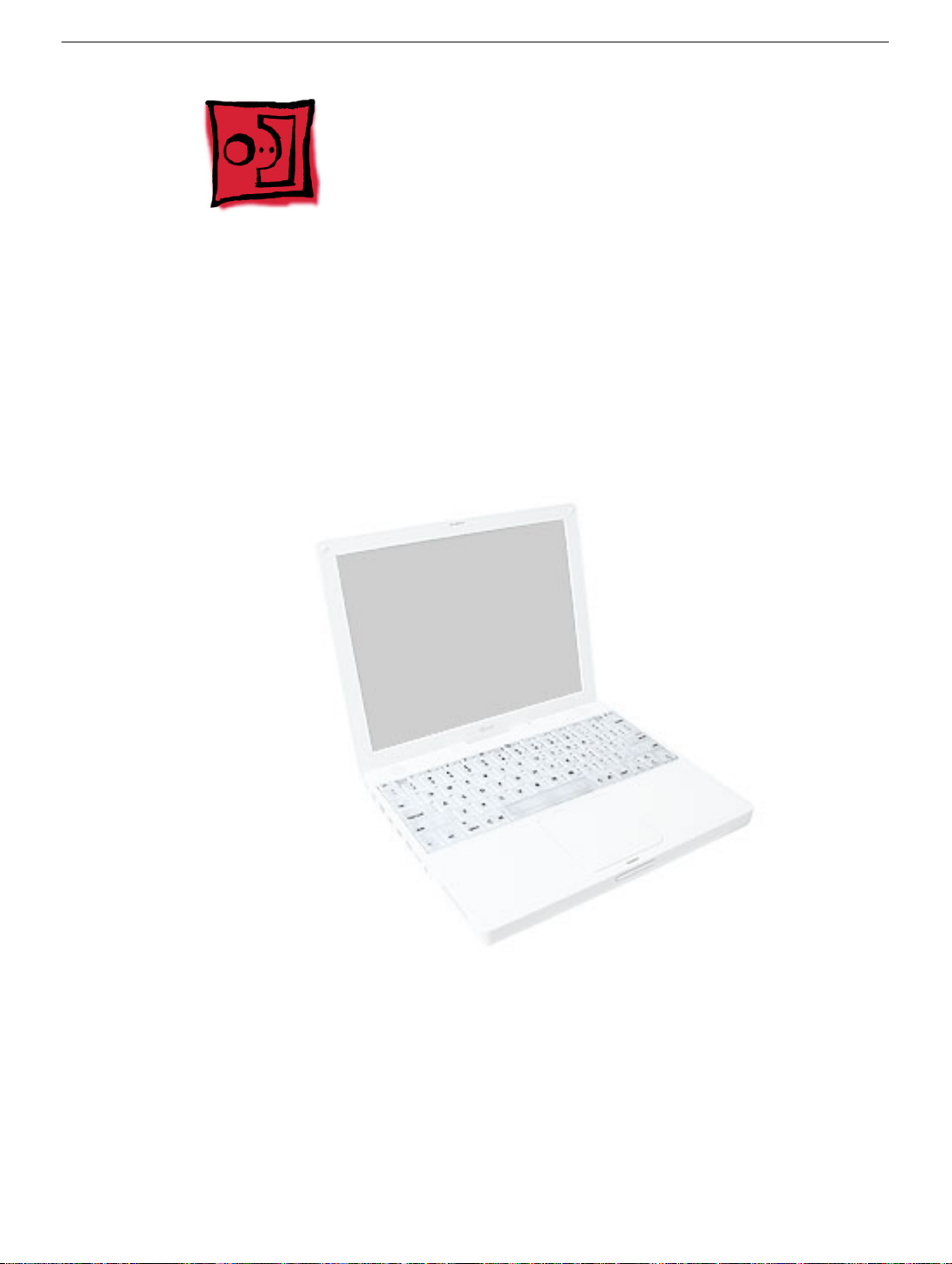
To easily distinguish this computer from previous iBook models, note these characteristics:
• iBook G4 identifier on display bezel
• Slot-load optical drive
• AirPort Extreme Card built in
• Mac OS X version 10.3.5 operating system
General Information
iBook G4 (12-inch Late 2004) Take Apart -
2
Page 4
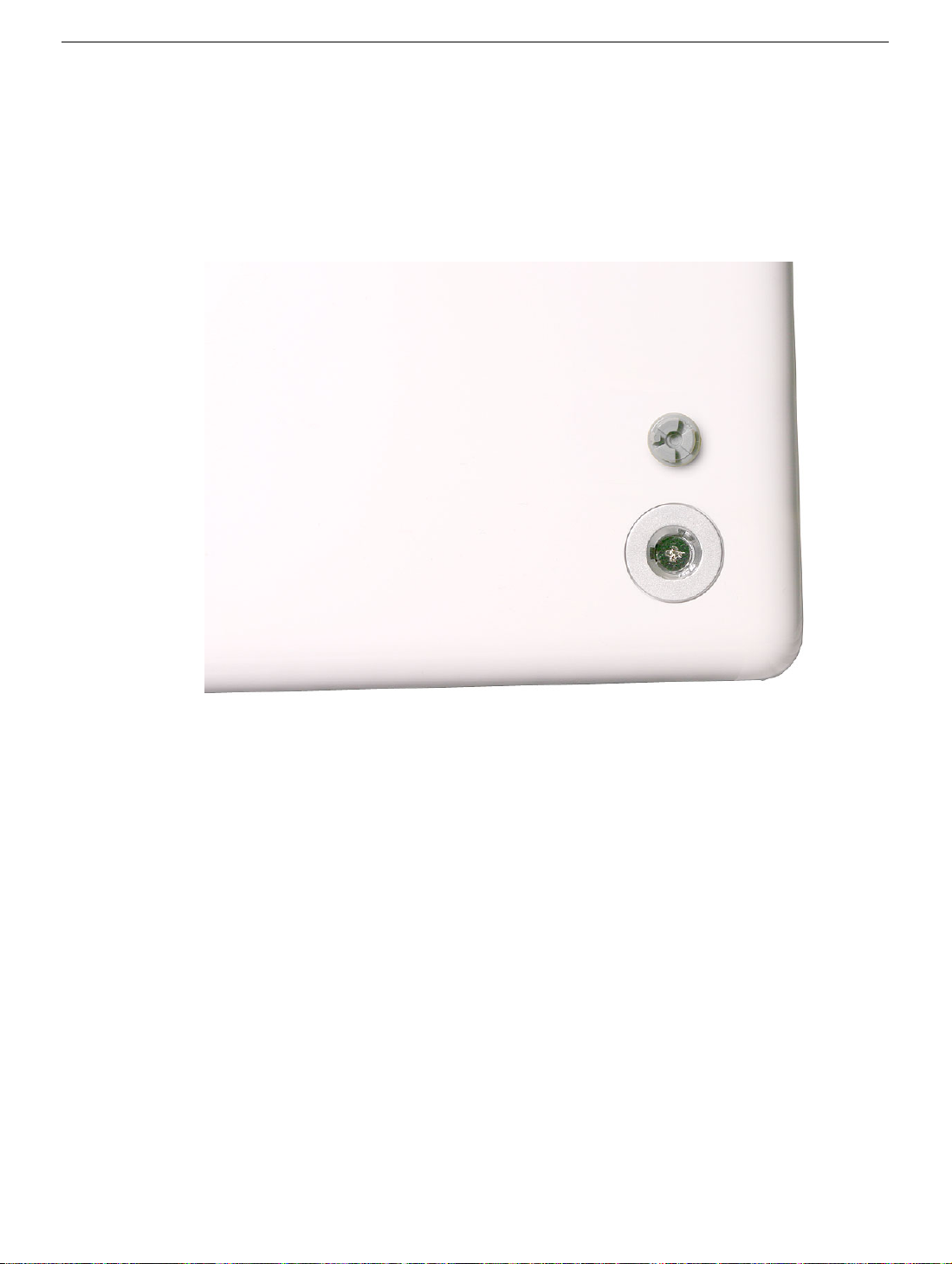
Important:
model is the appearance of the foot sockets. Check the foot sockets on the bottom case to
see this difference. For this model, the foot sockets are uniformly flat with no "dimples."
However, the foot sockets are compatible with earlier models, so this physical difference is
not an absolute indicator of the model type. Be sure to confirm the model type using serial
number verification.
The only noticeable physical difference between this model and the earlier G4
iBook G4 (Early 2004): Foot sockets include three "dimples"
iBook G4 (Late 2004): Foot sockets are uniformly flat
3 -
iBook G4 (12-inch Late 2004) Take Apart
General Information
Page 5
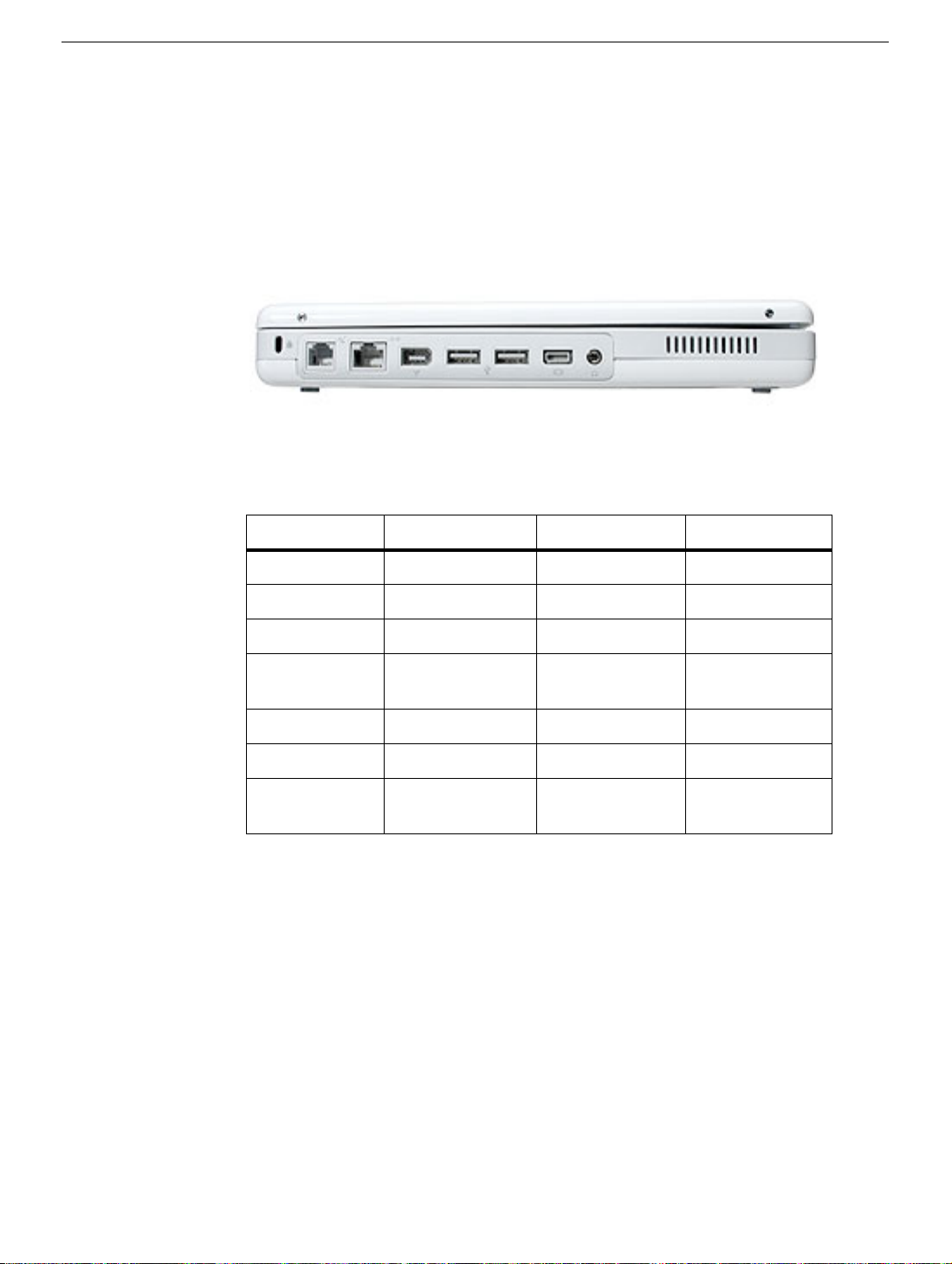
The ports on the left side of the computer are the same as the previous G4 model:
• RJ11 modem port
• Ethernet port
• FireWire port
• Two USB ports
• External display connector
• Headphone port
This table shows the iBook G4 (Late 2004) product configurations at initial product
introduction:
Configuration Good Better* Best*
Display Size 12.1 inch 14.1 inch 14.1 inch
Video RAM 32 VRAM 32 VRAM 32 VRAM
Processor 1.2 GHz 1.33 GHz 1.33 GHz
Optical Drive Combo (DVD-
ROM/CD-RW)
Combo (DVDROM/CD-RW)
SuperDrive
Hard Drive 30 GB 60 GB 60 GB
Memory 256 MB RAM 256 MB RAM 256 MB RAM
AirPort
card installed card installed card installed
Extreme
*
For servicing the 14.1-inch models, refer to the iBook G4 (14-inch Late 2004) service
manual.
Procedures
If you are familiar with taking apart iBook G4 computers, you will notice few service
differences with this iBook model:
• Foot sockets are uniformly flat with no "dimples."
• A pin is recommended for removing the rubber feet.
• The procedures for the cables, fan, modem, and heatsink differ somewhat from earlier
models.
• The number and types of screws differ somewhat from previous models.
General Information
iBook G4 (12-inch Late 2004) Take Apart -
4
Page 6
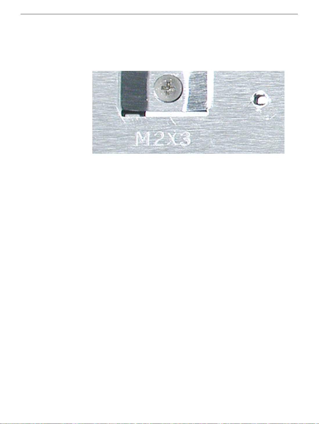
Note:
The top and bottom EMI shields are marked with screw identifiers for most of the
screw locations. The screw identifiers are in the form of "M2x_" where the last digit
indicates the approximate screw length. For example, a marking of "M2x3" indicates a 3.5mm long screw. Use the identifiers as a guide when reassembling the computer.
Tools
The following tools are recommended for the Take Apart procedures:
• Coin
• ESD wriststrap and mat
• Pin
• Magnetized #0 Phillips screwdriver
• Jeweler’s flat-blade screwdriver
• Small soft cloth
• Torx T8 screwdriver
• 2.0 mm hex nut driver
• Needlenose pliers
• Torx T6 screwdriver or 5/32 hex driver (for display housing)
• Black stick (or other nonconductive nylon or plastic tool)
Note:
To organize the screws you remove from the assembly, use a tray with divided
compartments (such as a plastic ice cube tray).
Serial Number Location
In this computer, the product serial number is located in two places:
• Battery bay
• Top case underneath the keyboard
5 -
iBook G4 (12-inch Late 2004) Take Apart
General Information
Page 7
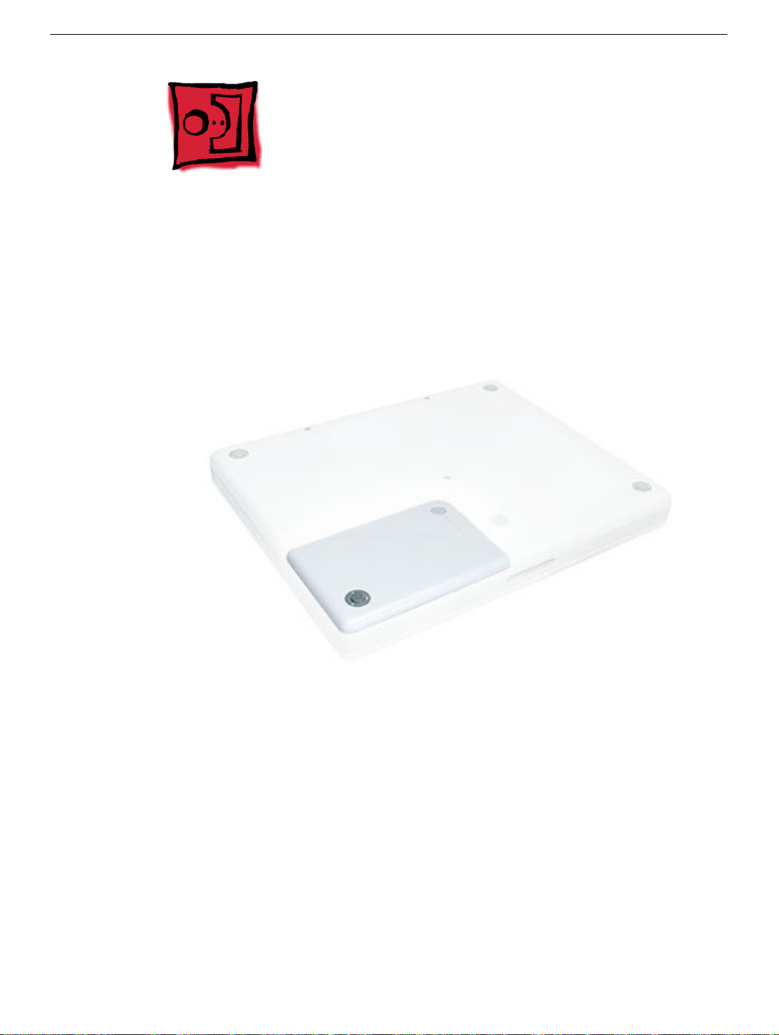
Battery
Tools
The only tool required for this procedure is a coin.
Part Location
Battery
Preliminary Steps
Warning: Always shut down the computer before opening it to avoid damaging its
internal components or causing injury. After you shut down the computer, the
internal components can be very hot. Let the computer cool down for 30 minutes
before continuing.
Procedure
Warning:
performing this procedure.
1. Place the computer on a clean, flat surface.
2. Shut down the computer and wait thirty minutes before continuing.
If the computer has been recently operating, allow it to cool down before
iBook G4 (12-inch Late 2004) Take Apart -
6
Page 8
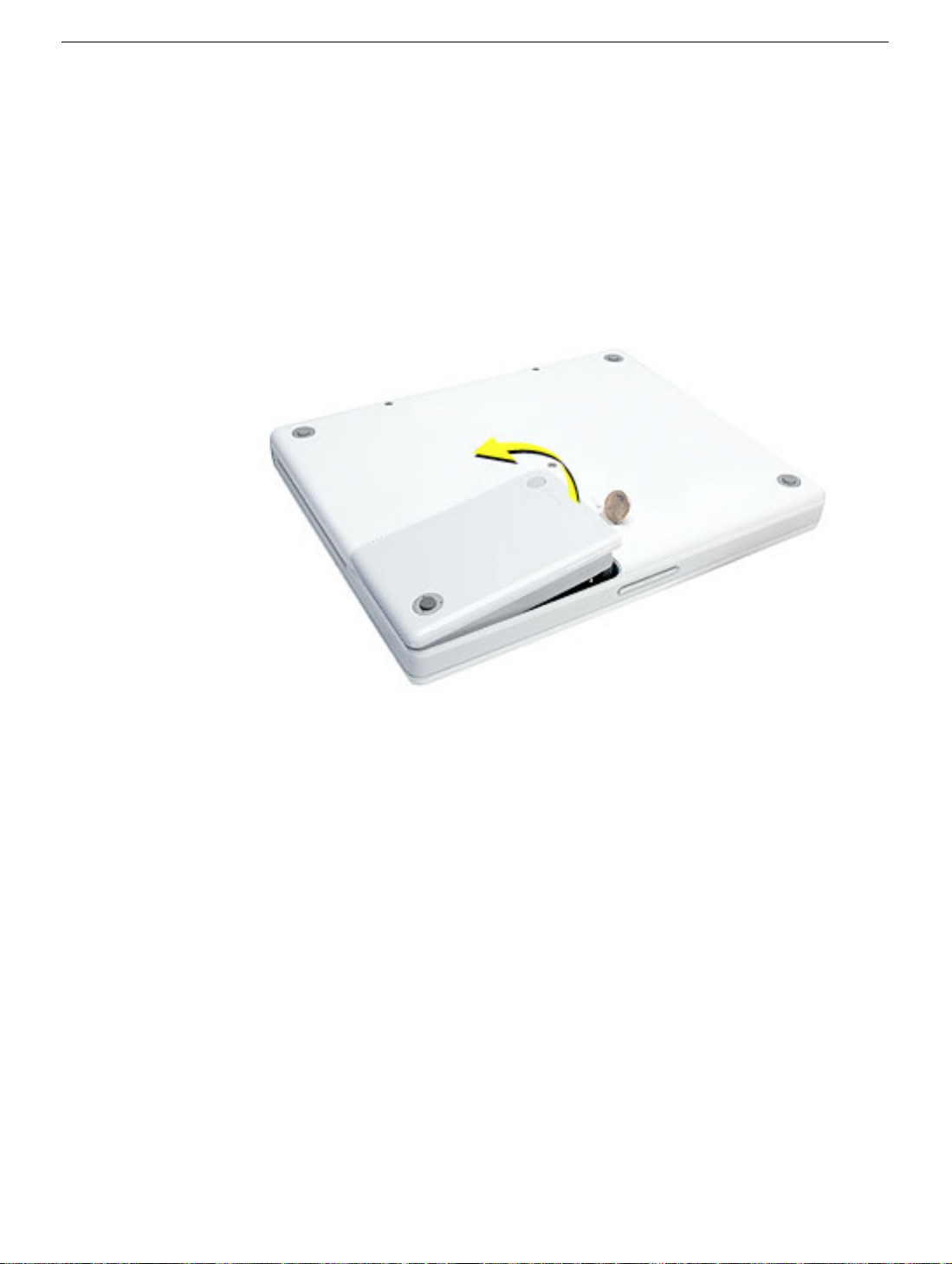
3. Disconnect the power cord and any other cables connected to the computer.
4. Close the computer, turn it over, and locate the battery latch.
Use a coin to turn the battery latch 1/4 turn clockwise to unlock the battery. Gently
remove the battery.
Removing the battery will prevent you from accidentally turning on the computer.
Warning: Removing the battery before shutting down the computer may result
in data loss.
5. Install the replacement battery.
6. Reconnect the power cord and any other cables that were connected and restart the
computer.
Note: You may need to reset the date and time (using the Date & Time control panel
in System Preferences).
Warning: Never turn on the computer unless all of its internal and external
parts are in place and it is fully reassembled. Operating the computer when it is
missing parts can damage the computer or cause injury.
7 -
iBook G4 (12-inch Late 2004) Take Apart
Battery
Page 9
Foot and Foot Socket
Tools
• Foot kit (for installing the replacement feet)
• Soft cloth
• Pin
• Needlenose pliers
• #0 Phillips jeweler’s screwdriver
Caution:
replace the foot and foot socket.
To avoid scratching the case, use caution when using tools to remove and
Part Location
Preliminary Steps
Warning: Always shut down the computer before opening it to avoid damaging its
internal components or causing injury. After you shut down the computer, the
internal components can be very hot. Let the computer cool down for 30 minutes
before continuing.
Foot and Foot Socket
iBook G4 (12-inch Late 2004) Take Apart -
8
Page 10
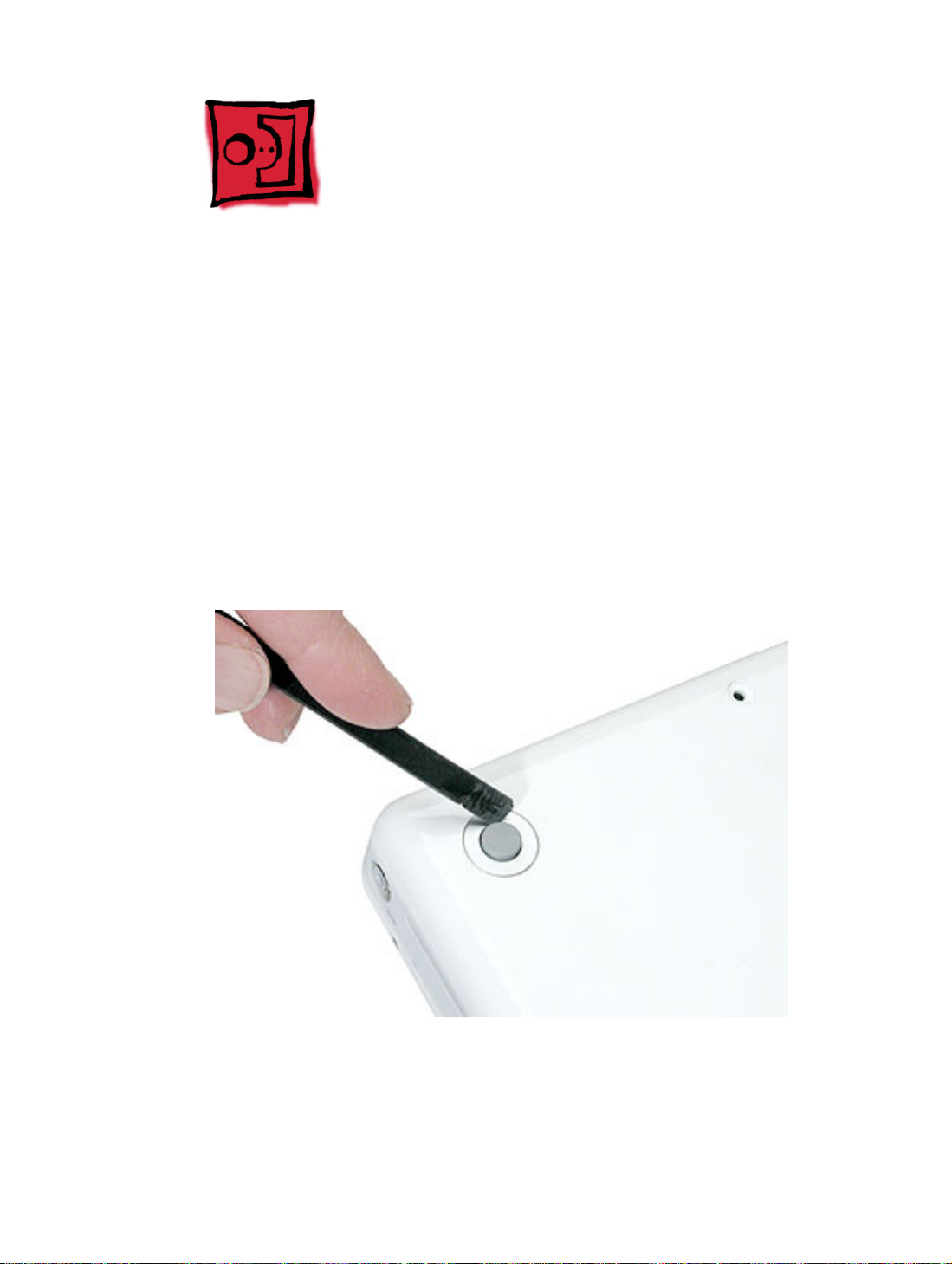
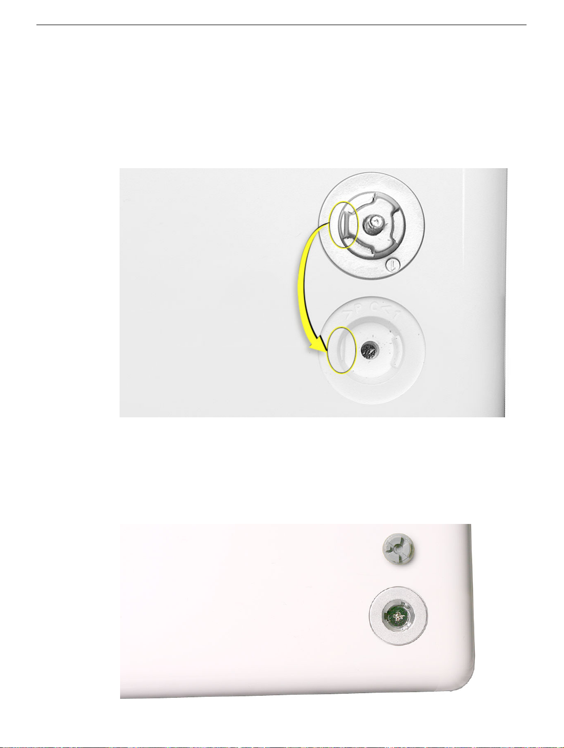
Procedure
Caution:
replace the foot.
1. Place the computer on a clean, flat surface or soft cloth.
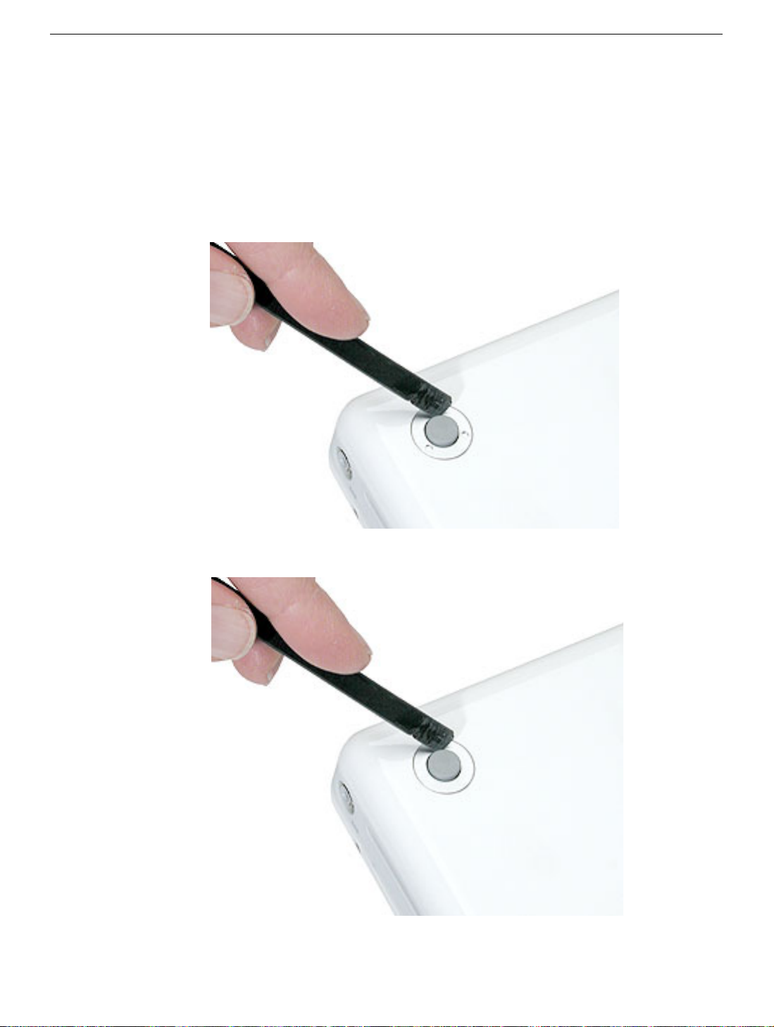
2. Use a pin in the area shown to wedge the rubber foot off of the socket.
To avoid scratching the case, use caution when using tools to remove and
9 -
iBook G4 (12-inch Late 2004) Take Apart
Foot and Foot Socket
Page 11
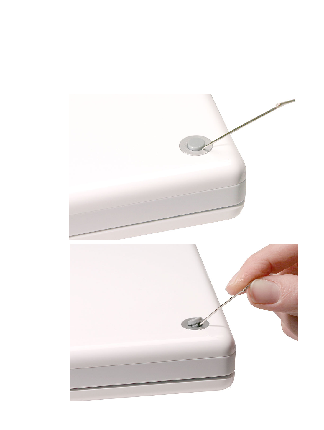
Note:
If a portion of the rubber foot remains on the bottom case, use tweezers or
needlenose pliers to carefully remove it.
3. Use a screwdriver to remove the screw and socket from the bottom case.
4. Repeat for the remaining two feet if you are replacing them or removing the bottom
case.
Foot and Foot Socket
iBook G4 (12-inch Late 2004) Take Apart -
10
Page 12
Replacing the Feet and Sockets
1. Install the new socket. For the best fit, do not reuse the old socket.
Replacement Note: When replacing the socket, notice the wedge area on the
bottom of the socket and the matching wedge area in the bottom case. Position the
socket in the bottom case to align the wedge areas. You might need to rotate the
socket slightly until it sits flat into the bottom case.
2.
With the socket sitting flat in the bottom case, install the screw.
3. Before installing the replacement foot, check the shape. The socket and foot are
keyed:
• The socket has three identical openings and a fourth indented area.
• The foot has three identical raised areas and a fourth smaller raised surface.
11 -
iBook G4 (12-inch Late 2004) Take Apart
Foot and Foot Socket
Page 13

4. Install the matching foot by aligning it to the matching areas in the socket. With gentle
even pressure, press the foot onto the socket.
5. Reassemble and test the computer.
Foot and Foot Socket
iBook G4 (12-inch Late 2004) Take Apart -
12
Page 14
Keyboard and RAM Shield
Tools
• #0 Phillips screwdriver
• Jeweler’s flat-blade screwdriver (if keyboard is locked)
• Small soft cloth
Part Location
Preliminary Steps
Before you begin, remove the battery.
13 -
iBook G4 (12-inch Late 2004) Take Apart
Keyboard and RAM Shield
Page 15
Procedure
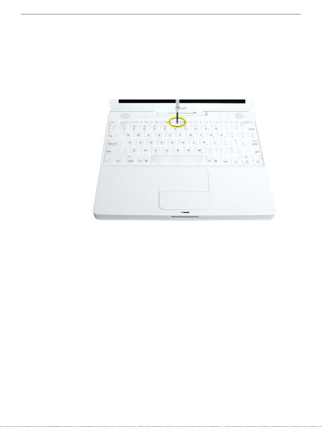
1. Raise the display so you can access the keyboard.
2. Make sure the keyboard locking screw, located in the small plastic tab next to the Num
Lock key, is not in the locked position. The iBook comes with the keyboard unlocked,
so unless you or someone else locked the keyboard, you can skip this step.
To unlock the keyboard, turn the screw 1/2 turn.
Keyboard and RAM Shield
iBook G4 (12-inch Late 2004) Take Apart -
14
Page 16
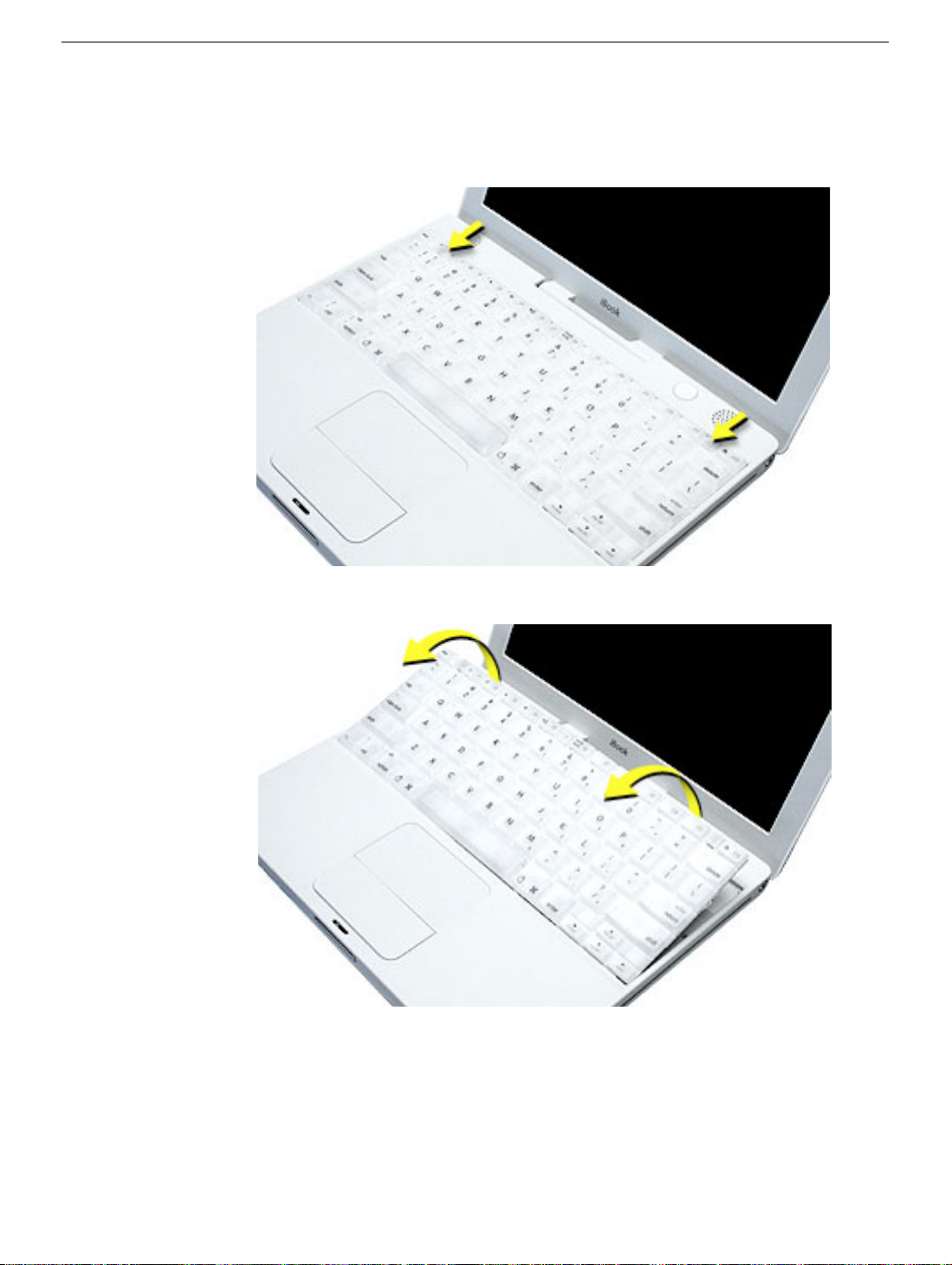
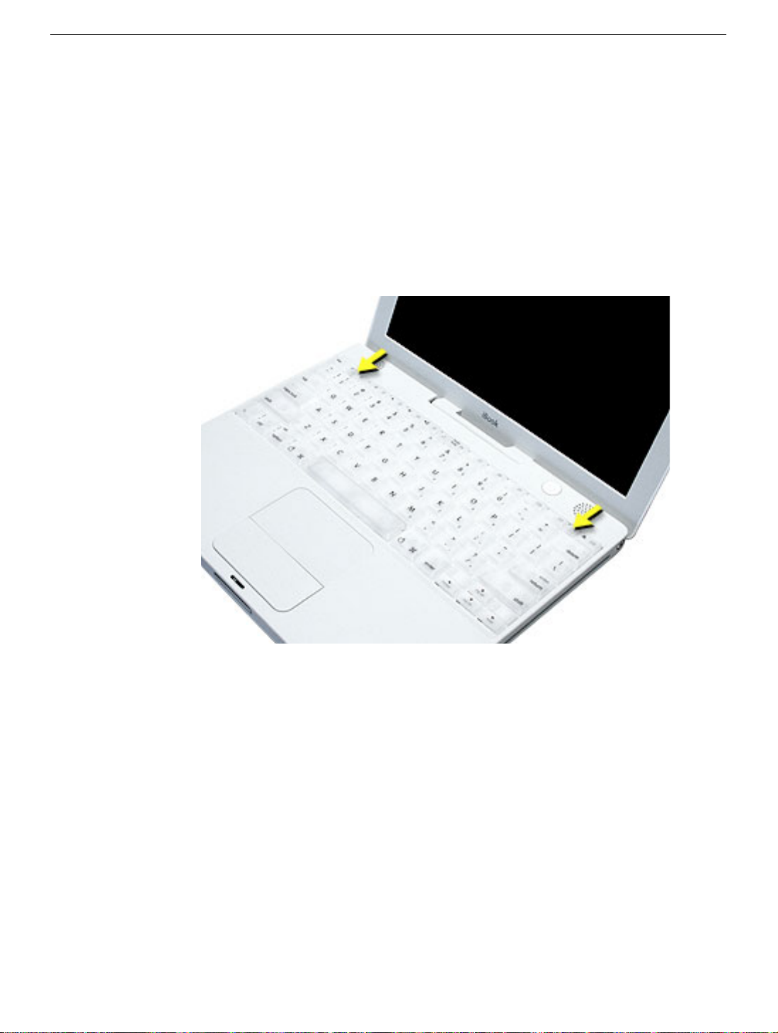
3. Release the keyboard by pulling down on the keyboard release tabs (located to the left
of the F1 and F12 keys), then lift the top portion of the keyboard up slightly, and toward
the display.
4. Flip the keyboard over and lay it on the palm rest.
15 -
iBook G4 (12-inch Late 2004) Take Apart
Keyboard and RAM Shield
Page 17
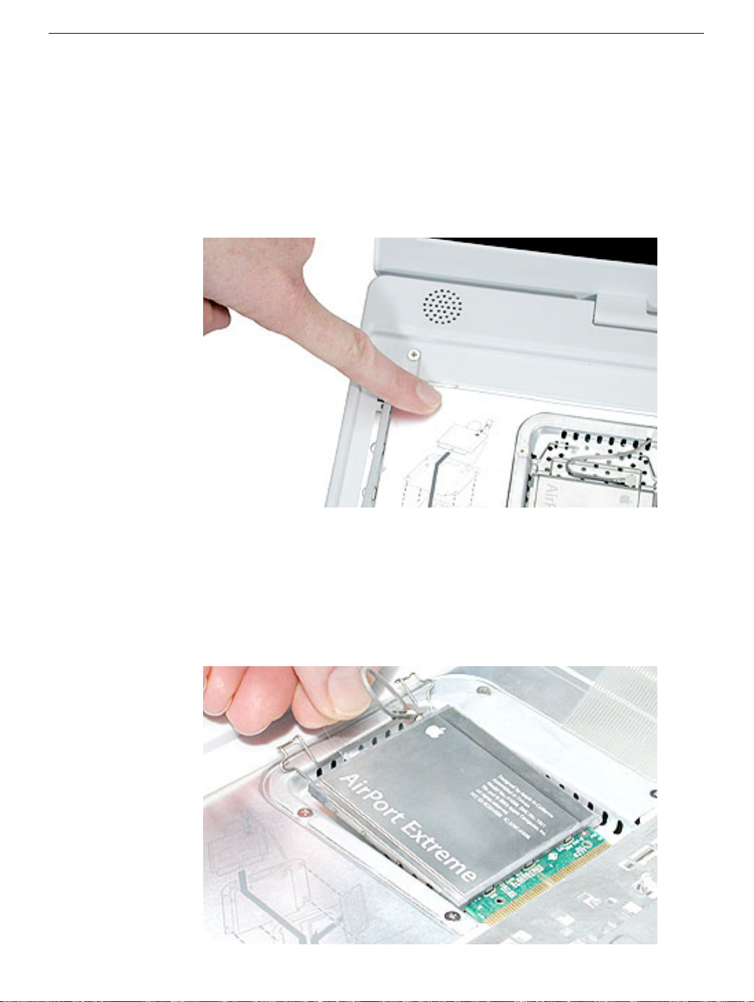
5. Touch a metal surface on the inside of the computer to discharge any static electricity,
as shown.
Important:
touching the computer’s framework before you touch any parts or install any
components inside the computer. To avoid static electricity building back up in your
body, do not walk around the room until you have completed the installation and
closed the computer.
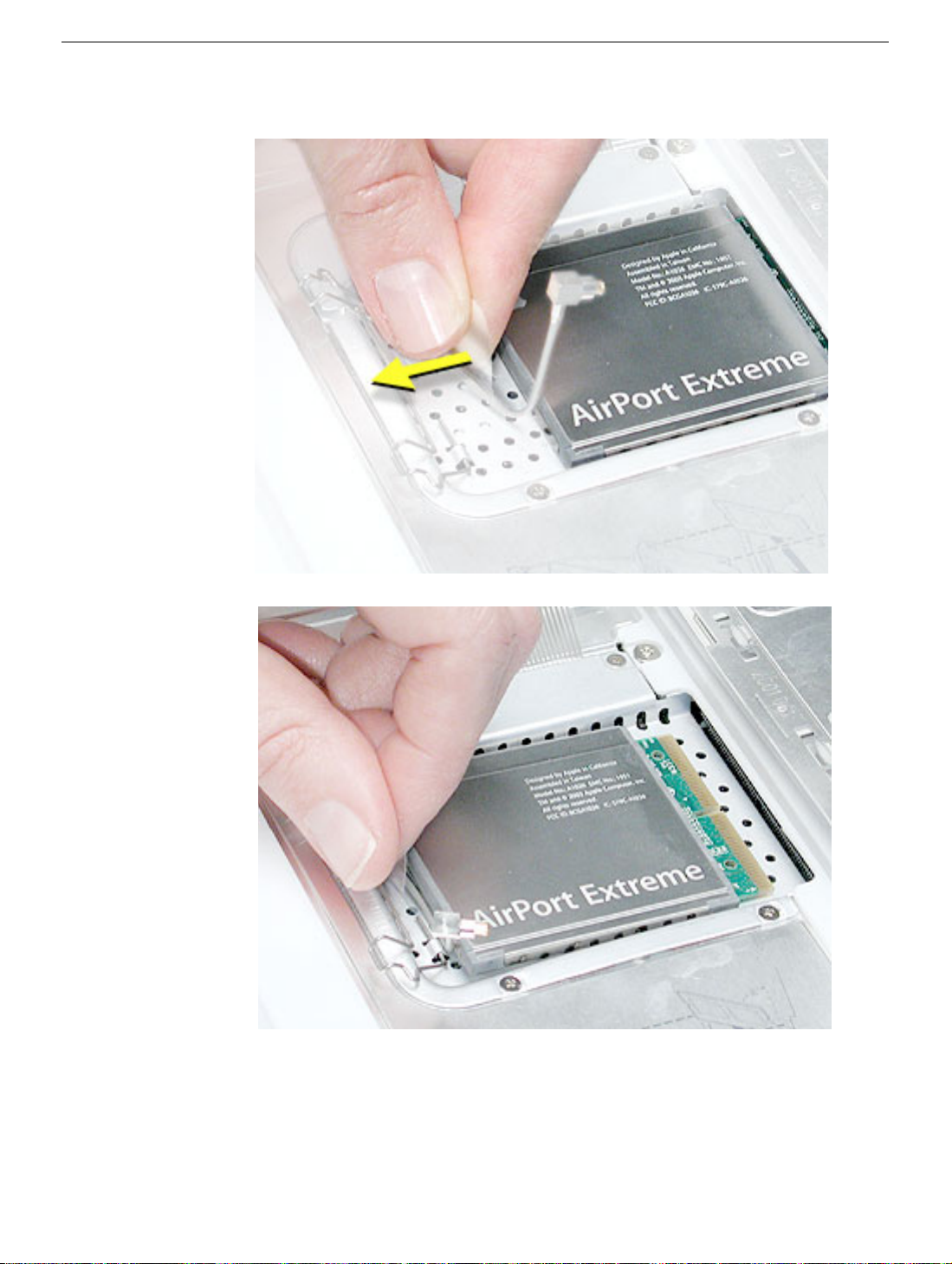
6. For the installed AirPort Extreme Card, unlatch the flexible wire bracket that secures
the card.
To avoid electrostatic discharge damage, always ground yourself by
Use the pull-tab on the card to remove it from the slot. (You do not need to
disconnect the antenna.)
Note:
To avoid scratching the computer’s case, place a soft cloth between the
AirPort Extreme Card and the surface of the iBook.
Keyboard and RAM Shield
iBook G4 (12-inch Late 2004) Take Apart -
16
Page 18
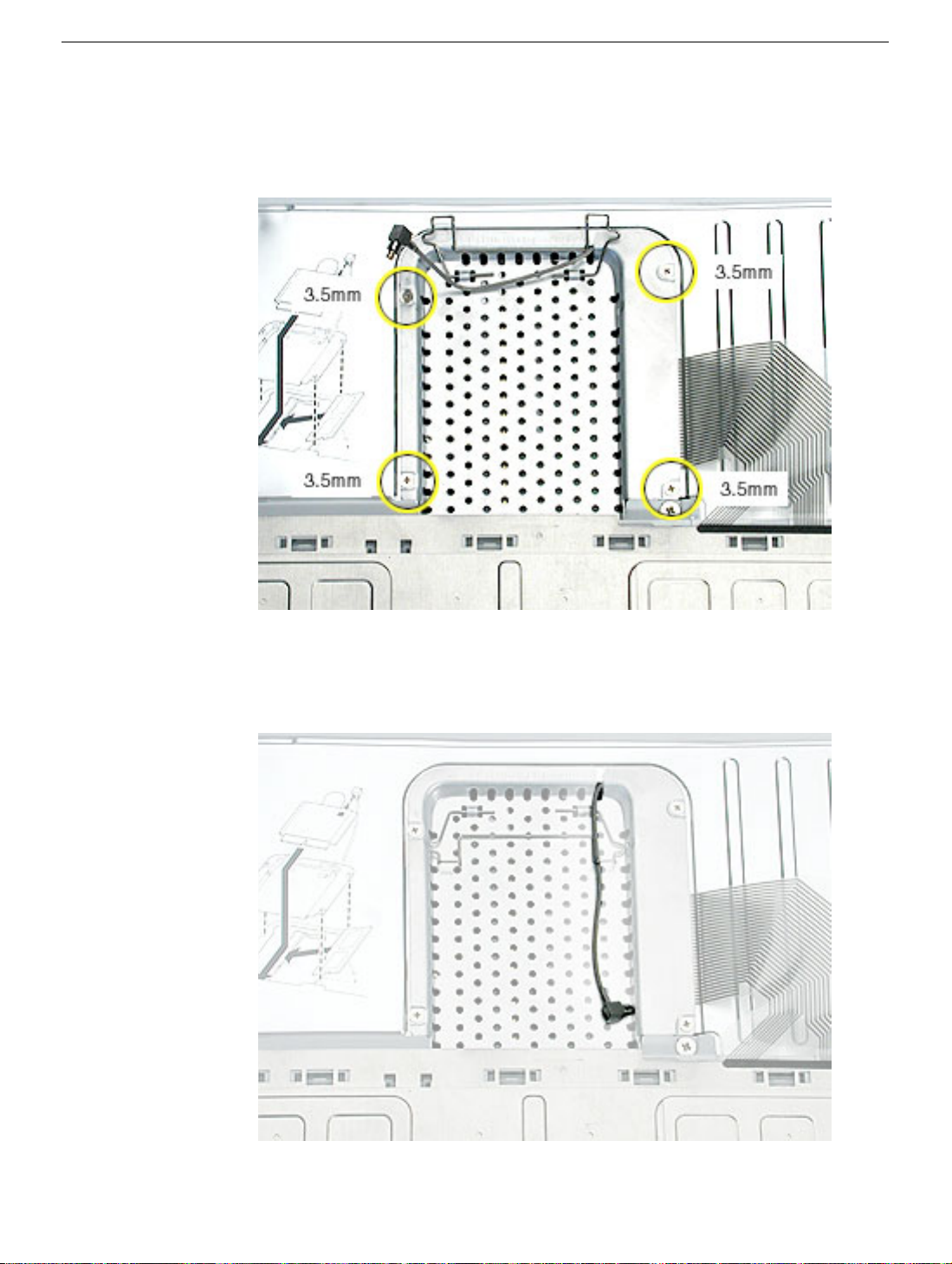
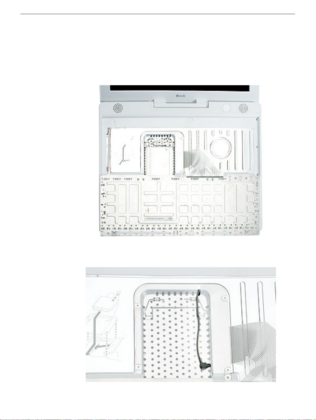
7. If an AirPort Extreme Card is not installed, unlatch the flexible wire bracket to release
the AirPort antenna cable.
8. Remove the four screws that secure the RAM shield.
Replacement Note:
the RAM shield, make sure the antenna cable is routed as shown if there is no
AirPort Extreme Card.
Note the routing of the AirPort antenna cable. When reinstalling
17 -
iBook G4 (12-inch Late 2004) Take Apart
Keyboard and RAM Shield
Page 19
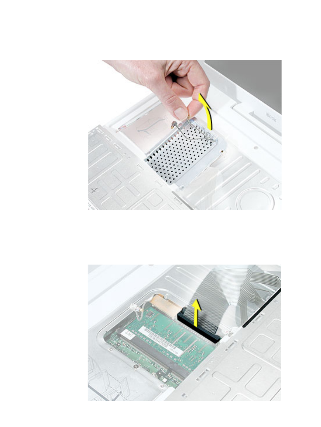
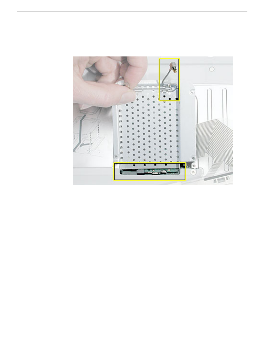
9. Lift the RAM shield out of the computer.
10. Route the AirPort antenna cable out of the slot in the RAM shield.
11. Locate the keyboard cable connector.
12. Firmly grasp the cable, and carefully pull it straight up until the connector releases.
Important:
Note:
Pull straight up; do not twist or pull the cable sideways.
If necessary, use your fingers to pry up the connector from side to side.
Keyboard and RAM Shield
iBook G4 (12-inch Late 2004) Take Apart -
18
Page 20
13. Install the replacement keyboard, RAM shield, and AirPort Extreme Card (if used).
Replacement Note:
and insert the lower end of the RAM shield in the keyboard well first.
Make sure the antenna cable fits into the slot in the RAM shield,
19 -
iBook G4 (12-inch Late 2004) Take Apart
Keyboard and RAM Shield
Page 21
Make sure the replacement keyboard is firmly seated:
• Flip the keyboard back toward the keyboard opening in the case.
• Hold the keyboard at a 45-degree angle above the keyboard opening, and insert
the tabs on the bottom edge of the keyboard into the slot under the edge of the
opening.
•
Important:
against the edge of the opening.
• Lay the keyboard flat into the keyboard opening.
• Pull down on the keyboard release tabs and then press down on the top portion of
the keyboard.
Make sure that all the tabs are seated and that the keyboard rests flush
Keyboard and RAM Shield
iBook G4 (12-inch Late 2004) Take Apart -
20
Page 22
AirPort Extreme Card
Tools
The only tool required for this procedure is a small soft cloth.
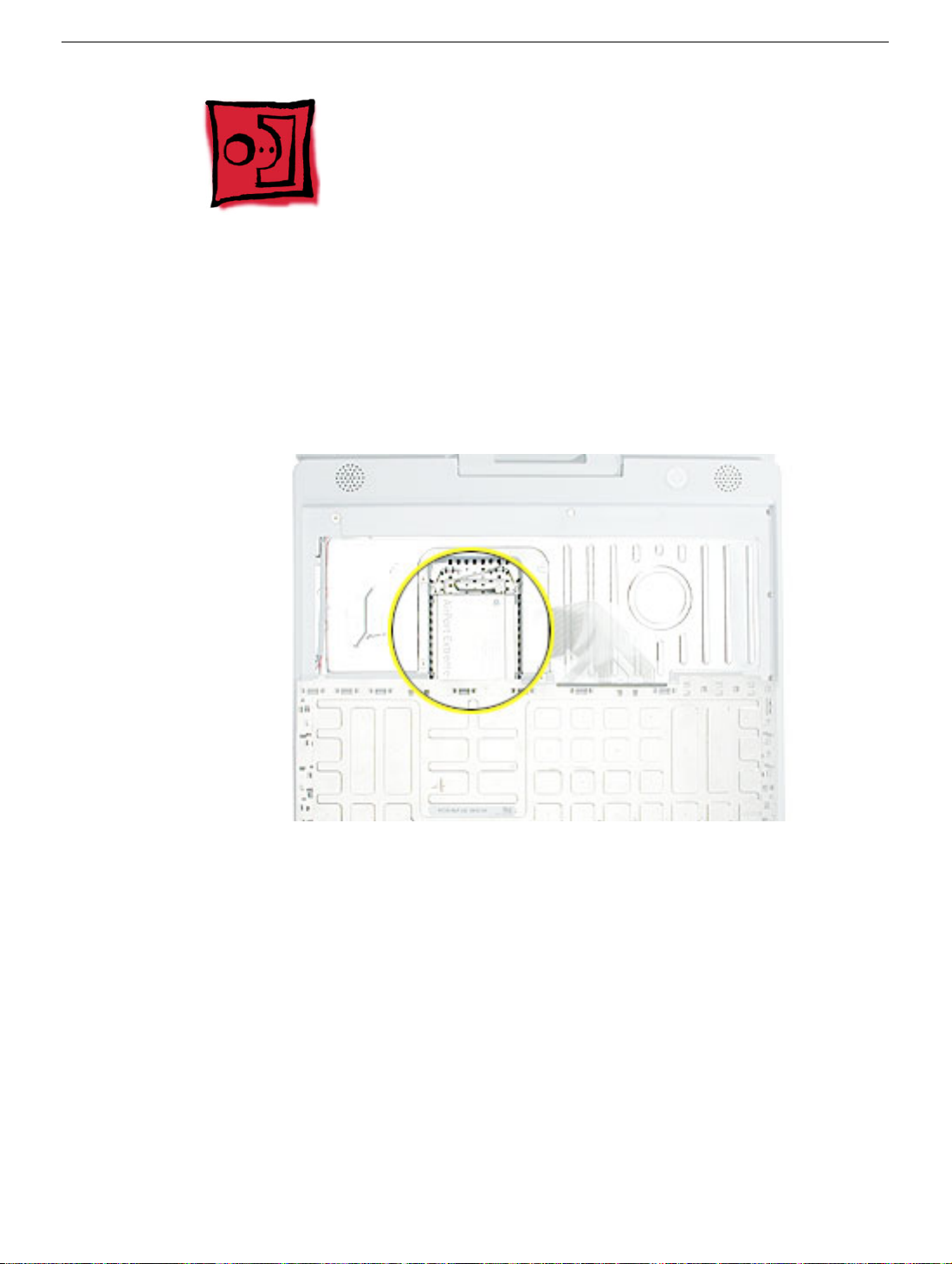
Part Location
Preliminary Steps
Before you begin, remove the following:
• Battery
• Keyboard (but do not disconnect the keyboard cable)
21 -
iBook G4 (12-inch Late 2004) Take Apart
AirPort Extreme Card
Page 23
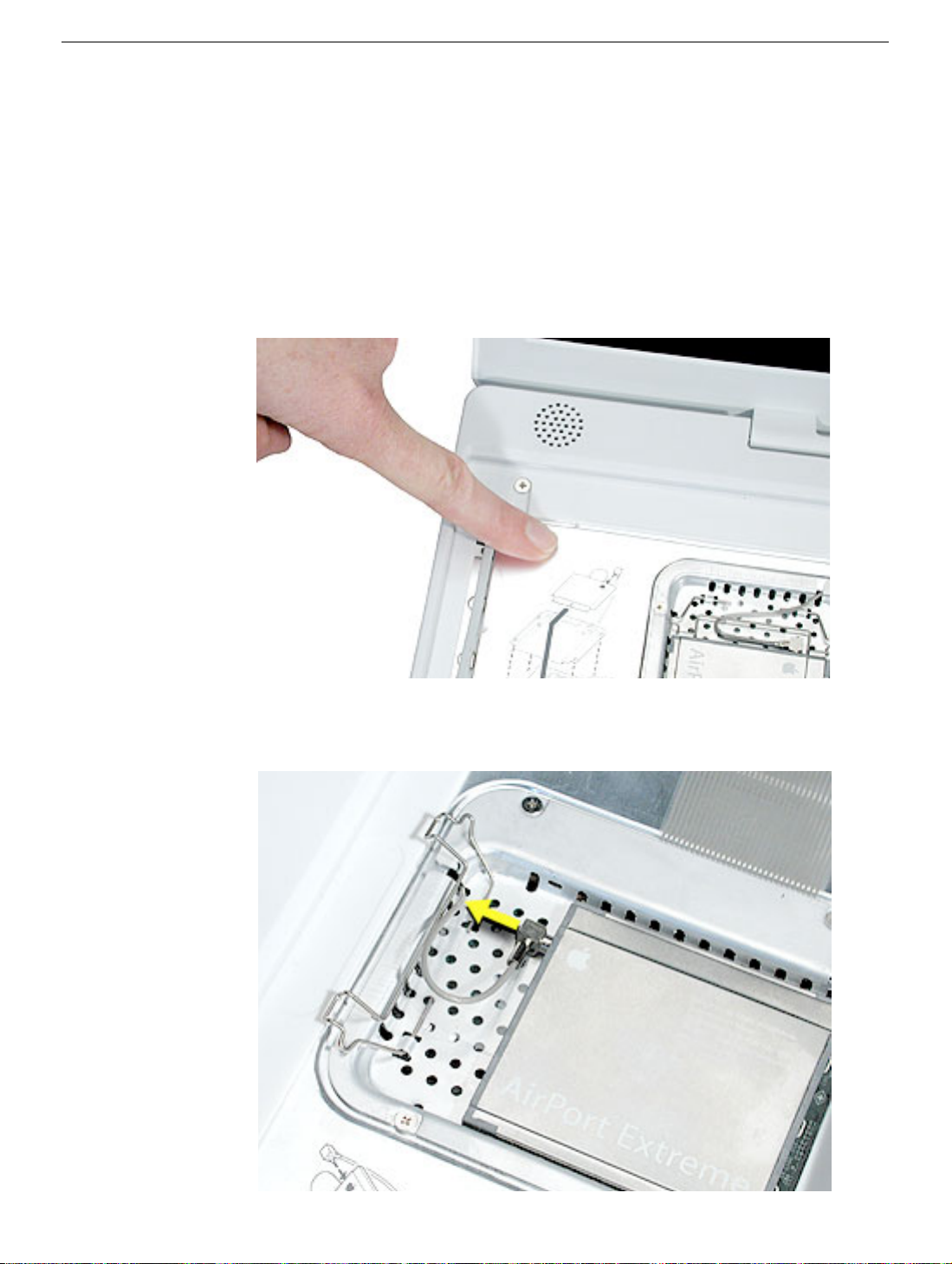
Procedure
1. Touch a metal surface on the inside of the keyboard well to discharge any static
electricity.
Important:
touching the computer’s framework before you touch any parts or install any
components inside the computer. To avoid static electricity building back up in your
body, do not walk around the room until you have completed the installation and
closed the computer.
2. Lift up the flexible wire bracket that secures the card.
To avoid electrostatic discharge damage, always ground yourself by
3. Detach the antenna cable from the AirPort Extreme Card.
AirPort Extreme Card
iBook G4 (12-inch Late 2004) Take Apart -
22
Page 24
4. Use the pull-tab on the card to remove the card from the slot.
23 -
iBook G4 (12-inch Late 2004) Take Apart
AirPort Extreme Card
Page 25
5. Install the replacement AirPort Extreme Card into the slot.
6. Plug the AirPort antenna cable connector into the port on the end of the replacement
card. Make sure the connector is straight before inserting it into the card.
Use the wire bracket to secure the AirPort Extreme Card in place by inserting its
prongs into the slots in the RAM shield.
Note:
be routed as shown.
7. Reassemble and test the computer.
AirPort Extreme Card
If no replacement AirPort Extreme Card is to be installed, the antenna cable should
iBook G4 (12-inch Late 2004) Take Apart -
24
Page 26
Memory Card
Warning: Memory cards come in various specifications. Only install memory cards
that are approved for this computer.
Tools
The only tool required for this procedure is a small soft cloth.
Part Location
Preliminary Steps
Before you begin, remove the following:
• Battery
• Keyboard and RAM shield (but do not disconnect the keyboard cable)
• AirPort Extreme Card
25 -
iBook G4 (12-inch Late 2004) Take Apart
Memory Card
Page 27
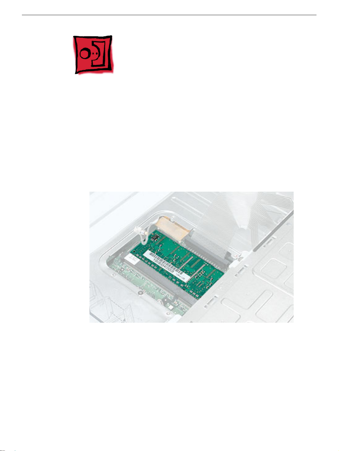
Procedure
1. Locate the installed memory card and brackets that secure the card on both sides.
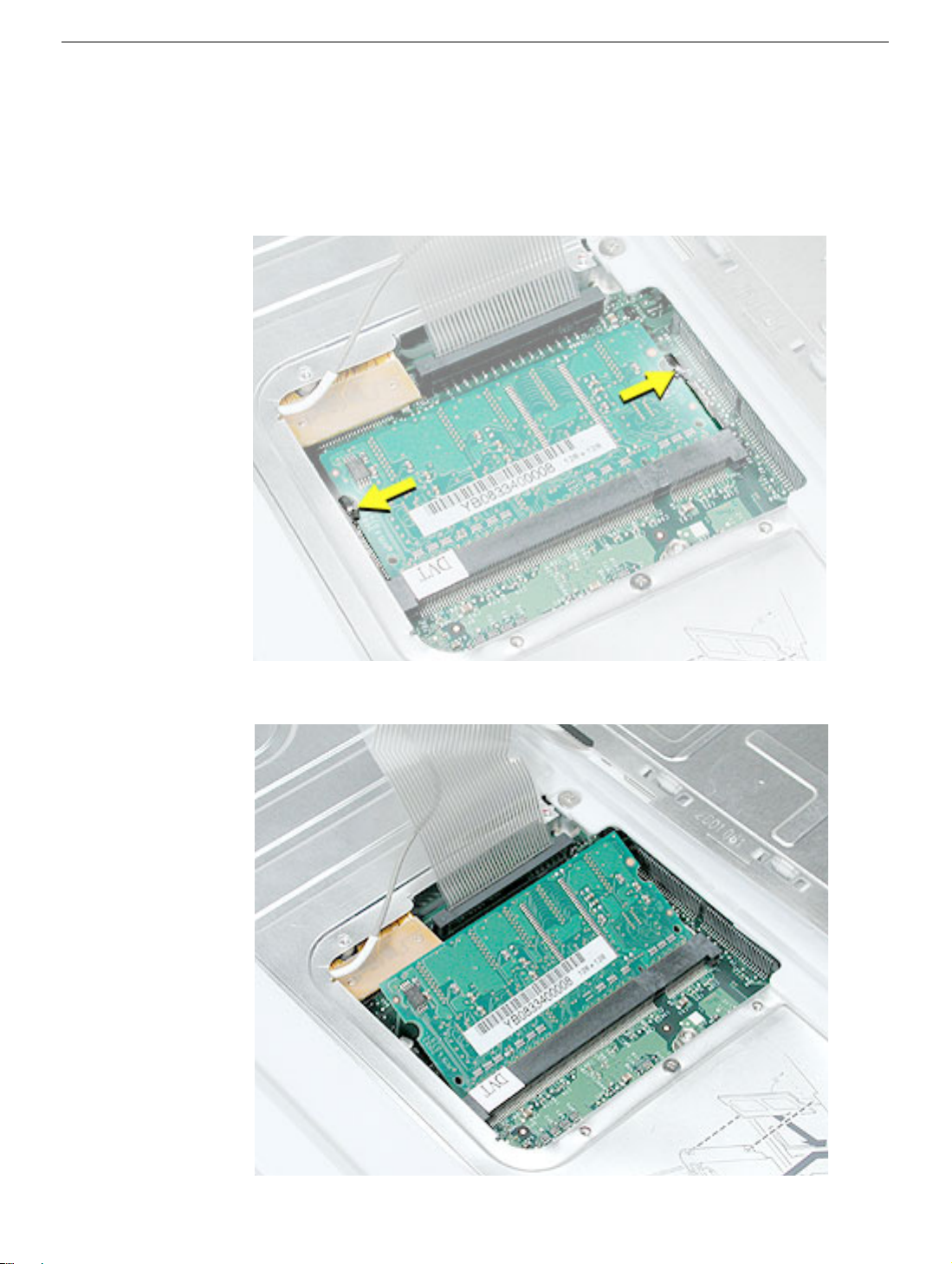
2. Carefully spread the brackets away from the notches in the card until the card
releases on each side.
3. Pull the card up and out of the memory slot.
Memory Card
iBook G4 (12-inch Late 2004) Take Apart -
26
Page 28
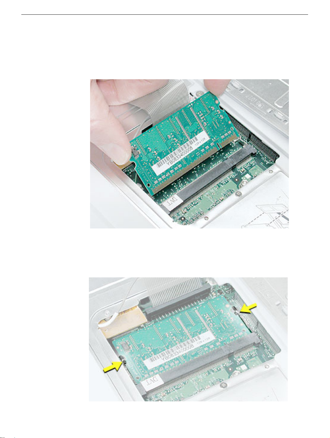
4. Align the notch in the replacement memory card with the small tab in the memory slot.
Hold the card at a 30-degree angle, then push the card into the slot until it is firmly
seated.
Note:
If you feel resistance when inserting the card, try pushing one side at a time.
5. Gently push the top of the card down until the brackets snap onto both sides of the
memory card to lock it into place.
Warning: Apply gentle pressure to the memory card only. Pressing on nearby
connectors or components can cause electrical damage.
6. Reassemble and test the computer.
27 -
iBook G4 (12-inch Late 2004) Take Apart
Memory Card
Page 29
Bottom Case
Tools
• Soft cloth
• Torx T8 screwdriver or 2.0 mm hex nut driver
• Black stick (or other nonconductive nylon or plastic tool)
• #0 Phillips screwdriver
Part Location
Bottom Case
Preliminary Steps
Before you begin, remove the battery.
iBook G4 (12-inch Late 2004) Take Apart -
28
Page 30
Procedure
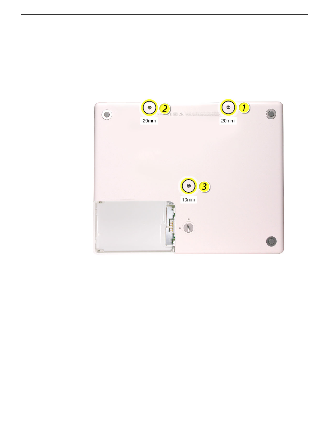
1. Place the computer upside down on a soft cloth.
2.
Important:
slip out of the screw head during removal.
Remove the three screws.
To avoid damaging the case, be careful that the screwdriver tip does not
29 -
iBook G4 (12-inch Late 2004) Take Apart
Bottom Case
Page 31

3. Using a pin, pry up the three rubber feet from the metal sockets.
Note: When reassembling the computer, do not reuse the feet. Install three new
rubber feet.
4. Remove the three identical Phillips screws from the metal sockets.
5. Use a black stick to lift out the metal sockets.
Note: When reassembling the computer, note that the metal sockets are keyed.
Rotate them until they sit flat against the bottom case.
Bottom Case
iBook G4 (12-inch Late 2004) Take Apart - 30
Page 32

6. Remove the two identical Phillips screws next to the battery connector.
31 - iBook G4 (12-inch Late 2004) Take Apart
Bottom Case
Page 33

7. Note the locations of the slots on the bottom case pictured below. The computer frame
has tabs that fit into slots within the bottom case (six tabs in front; two on each side;
three in back). When using a black stick to pry off the bottom case, it helps to know
where the slots are as you free the tabs from the slots.
8. Starting at the battery compartment, use a black stick to carefully pry up the bottom
case from the computer.
Bottom Case
iBook G4 (12-inch Late 2004) Take Apart - 32
Page 34

9. Warning: To avoid damaging the sleep light and other delicate components, do
not insert the black stick too far into the computer as you free the bottom case
from the computer. Use just the tip of the black stick to pry up the bottom case.
10. Carefully work the black stick around the corners of the bottom case.
11. The bottom case fits snugly. Use moderate force to remove the tabs from the slots.
12. In the battery compartment, lift up the corner of the bottom case, and use a black stick
or jeweler’s flat-blade screwdriver to gently pry up the slot from the inner tabs on the
frame.
33 - iBook G4 (12-inch Late 2004) Take Apart
Bottom Case
Page 35

13. Loosen the tabs from the slot load area last.
Pull up on the port side of the bottom case.
Placing the black stick nearly parallel to the slot drive opening, carefully free the case
from the remaining tabs at the slot drive side of the computer.
Note: When reassembling the computer, be careful not to pinch any cables as
you press the bottom case back onto the computer. Check that the bottom case
shows no raised surfaces and is fully snapped into place before installing the
remaining screws, sockets, and feet.
Bottom Case
iBook G4 (12-inch Late 2004) Take Apart - 34
Page 36

14. If you are replacing any additional parts at this time, remove the two springs from the
battery compartment so they do not fall out and get lost.
Note: When reassembling the computer, make sure that the two springs in the
battery compartment are in place before installing the bottom case. Each spring has
a plastic cap on one end. The cap should fit securely on the spring, and the curved
side of the cap should be positioned against the inner frame. The springs have a
small amount of grease on them; do not wipe away the grease.
15. Install the replacement bottom case, and reassemble and test the computer.
35 - iBook G4 (12-inch Late 2004) Take Apart
Bottom Case
Page 37

Bottom Shield
Tools
• Soft cloth
• #0 Phillips screwdriver
• Black stick (or other nonconductive nylon or plastic tool)
Note: To organize the screws you remove from the computer, use a tray with divided
compartments (such as a plastic ice cube tray).
Part Location
Bottom Shield
Preliminary Steps
Before you begin, remove the following:
• Battery
• Bottom case
iBook G4 (12-inch Late 2004) Take Apart - 36
Page 38

Procedure
1. With the computer on a soft cloth, remove the four Phillips screws from the bottom
case.
2. Peel up, but do not remove, any pieces of tape.
Note: When reassembling the computer, reuse the tape to secure the replacement
bottom shield.
Replacement Note: When reassembling the computer, install the replacement
bottom shield so that the corner of the shield closest to the ports is secured first.
(With the computer oriented as shown, this corner is the uppermost right corner.)
When reinstalling the screws, install them in the order shown.
3. Peel up the tape, if present, at the computer latch. If the tape tears, replace it with new
aluminum tape.
37 - iBook G4 (12-inch Late 2004) Take Apart
Bottom Shield
Page 39

4. Warning: Do not bend the bottom shield.
Lift the bottom shield off the computer.
5. Note: The two springs in the battery compartment can become loose. When
reassembling the computer, make sure that the two springs are in place before
installing the bottom case. Each spring has grease on the coils, and each has a plastic
cap on one end. Make sure the cap fits securely on the spring, and the curved side of
the cap is positioned against the inner frame.
Bottom Shield
iBook G4 (12-inch Late 2004) Take Apart - 38
Page 40

6. Install the replacement bottom shield, and reassemble and test the computer.
Replacement Note: Before installing the bottom shield, make sure cables are routed
as shown.
39 - iBook G4 (12-inch Late 2004) Take Apart
Bottom Shield
Page 41

How to Add Spiral Tubing to Protect the Inverter Cable
The inverter cable can be pinched or damaged during reassembly of the bottom case. To
protect the inverter cable, add spiral tubing to the cable, as shown in this procedure.
Note: Images in this section are representative of iBook models.
Important: Do not pull, twist, or strain the cable as you perform this procedure.
Tools
• Soft cloth
• Black stick (or other nonconductive nylon or plastic tool)
Preliminary Steps
Before you begin, remove the following:
• Battery
• Bottom case
• Bottom shield
Procedure
1. With the computer on a soft cloth, peel up the tape that secures the inverter cable to
the frame.
2. Disconnect the inverter cable from the bottom of the logic board.
How to Add Spiral Tubing to Protect the Inverter Ca-
iBook G4 (12-inch Late 2004) Take Apart - 40
Page 42

3. Release the cable from the channel in the frame.
4. Holding the cable steady, wrap the spiral tubing around the cable at the clutch.
5. Make sure the tubing covers the cable where it exits the display.
6. Route the cable through the channel in the frame, and connect it to the logic board.
41 - iBook G4 (12-inch Late 2004) Take Apart
How to Add Spiral Tubing to Protect the Inverter Ca-
Page 43

7. Important: Create enough slack in the cable near the connector to relieve tension on
the cable. Secure the connector and cable with a strip of Kapton tape, as shown.
8. Reassemble and test the computer.
How to Add Spiral Tubing to Protect the Inverter Ca-
iBook G4 (12-inch Late 2004) Take Apart - 42
Page 44

DC-In Board
Tools
• Soft cloth
• #0 Phillips screwdriver
• Black stick (or other nonconductive nylon or plastic tool)
Part Location
Preliminary Steps
Before you begin, remove the following:
• Battery
• Bottom case
• Bottom shield
43 - iBook G4 (12-inch Late 2004) Take Apart
DC-In Board
Page 45

Procedure
1. With the computer on a soft cloth, disconnect the DC-in cable from the underside of
the logic board.
2. Remove any tape that holds the cable to the frame or logic board.
3. Route the cable from the guides in the chassis.
DC-In Board
iBook G4 (12-inch Late 2004) Take Apart - 44
Page 46

4. Remove the two identical screws from the DC-in board.
5. Tilt up the DC-in board, and pivot it out of the frame.
6. Remove the DC-in board from the computer assembly.
45 - iBook G4 (12-inch Late 2004) Take Apart
DC-In Board
Page 47

7. Install the replacement DC-in board, and reassemble and test the computer.
Replacement Note: The cable at the connector adheres to the logic board with
Kapton tape. Re-use the tape if it is still sticky. Otherwise, replace the Kapton tape.
DC-In Board
iBook G4 (12-inch Late 2004) Take Apart - 46
Page 48

Fan
Tools
• Soft cloth
• #0 Phillips screwdriver
• Black stick (or other nonconductive nylon or plastic tool)
Part Location
Preliminary Steps
Before you begin, remove the following:
• Battery
• Bottom case
• Bottom shield
47 - iBook G4 (12-inch Late 2004) Take Apart
Fan
Page 49

Procedure
1. With the computer on a soft cloth, remove any tape that holds the fan and cable in
place.
2. Disconnect the fan cable from the logic board.
3. Remove the four identical screws from the fan.
Replacement Note: When reassembling the computer, the replacement fan might
include a piece of tape that secures the cable to the body of the fan. Make sure the
tape is not blocking the fan blade movement.
Fan
iBook G4 (12-inch Late 2004) Take Apart - 48
Page 50

4. Lift the fan from the computer, and use a black stick to disconnect the connector from
the logic board.
5. Install the replacement fan, and reassemble and test the computer.
Replacement Note: Before installing the fan, make sure it is securely connected,
and fresh tape is applied.
49 - iBook G4 (12-inch Late 2004) Take Apart
Fan
Page 51

Top Case
Tools
This procedure requires the following tools:
• Soft cloth
• Jeweler’s flat-blade screwdriver
• #0 Phillips screwdriver
• Black stick (or other nonconductive nylon or plastic tool)
Note: To organize the screws you remove from the computer, use a tray with divided
compartments (such as a plastic ice cube tray).
Part Location
Top Case
iBook G4 (12-inch Late 2004) Take Apart - 50
Page 52

Preliminary Steps
Before you begin, remove the following:
• Battery
• Keyboard and RAM shield
• AirPort Extreme Card
• Memory card
• Bottom case
• Bottom shield
• DC-in board
Procedure
1. With the computer upside down on a soft cloth, remove the two screws from the
battery bay.
51 - iBook G4 (12-inch Late 2004) Take Apart
Top Case
Page 53

2. Turn over the computer.
3. Remove the three identical screws from the keyboard well near the slot load drive
opening.
4. Remove the remaining screws in the keyboard well:
• Using a small flat-blade screwdriver, pry up the magnet. Then remove the 4.5-mm
long screw beneath it.
• 6-mm long screw with large screw head at upper left corner of keyboard well
• 6-mm long screw at lower left corner of keyboard well
• 6-mm long screw with large screw head near keyboard cable connector
Note: When reassembling the computer, be sure to install the magnet over the
screw.
Replacement Note: When reinstalling the top case screws, install them in the order
shown.
Top Case
iBook G4 (12-inch Late 2004) Take Apart - 52
Page 54

5. Peel up the cosmetic tape that runs the length of the speaker wire, but make sure that
the speaker wire beneath it remains in place. Set aside the speaker wire tape.
Note: When reassembling the computer, reuse the speaker wire tape, but make sure
the speaker wire is lying flat on the top shield, as shown, before applying the tape.
Note: When reassembling the computer, ensure that the shrink tubing section of the
speaker cable sticks to the top shield and is routed as shown.
53 - iBook G4 (12-inch Late 2004) Take Apart
Top Case
Page 55

6. Use a soft cloth to protect the computer.
7. Using a black stick, begin to carefully separate the top case from the computer
assembly.
Reposition the computer as you work around the top case to open up the seam that
joins the top case and bottom case.
8. While continuing to loosen the top case, use caution around the battery bay. If
necessary, flex the inner frame to release that corner of the top case.
Top Case
iBook G4 (12-inch Late 2004) Take Apart - 54
Page 56

9. Warning: The top case is connected to the computer assembly with delicate
cables. Do not remove the top case until the cables are disconnected (see the
next steps).
Warning: When performing this step, make sure the speaker cable and shorter
power switch cable are not strained.
With most of the top case loosened, raise up the top case so you can see the shorter
power switch cable and the longer speaker cable.
10. With the cables still attached, position the top case so it is somewhat off center and
you can see the connectors at the lower edge of the keyboard well.
11. At the bottom edge of the keyboard well, use a black stick to carefully disconnect the
two cables from the logic board.
55 - iBook G4 (12-inch Late 2004) Take Apart
Top Case
Page 57

12. Slide the top case up to reach the cable at the top corner. Disconnect the cable.
Replacement Note: When connecting the speaker cable, make sure the wires are
routed under the top shield as shown.
Top Case
13. Remove the top case from the computer.
iBook G4 (12-inch Late 2004) Take Apart - 56
Page 58

14. Before installing the replacement top case, make sure it includes the following:
• Speaker set
• Power button and board (under left speaker)
• Speaker cable and power switch cable
• Trackpad assembly with board and cable
• Display latch
• Sleep magnet (on palm rest below left speaker)
– Replacement Note: The sleep magnet can pop off during the top case removal.
Make sure the sleep magnet is in place when replacing the top case.
Important: Make sure you transfer the original serial number label and Ethernet label
from the old top case to the replacement top case. You can use a black stick to
carefully peel up a corner of the label. Then peel off the label completely and apply it
to the replacement top case. Make sure that the labels lie completely flat so they do
not interfere with the battery compartment.
57 - iBook G4 (12-inch Late 2004) Take Apart
Top Case
Page 59

15. Before installing the top case, make sure a foam pad is positioned correctly on the
metallic surface by the trackpad board.
If the foam pad is missing, order a trackpad kit (Apple part number 076-1078), and
apply one of the adhesive foam pads.
Note: In the images shown below, the trackpad cable pictured differs from the
trackpad on the computer. However, the placement of the foam is correct.
Top Case
iBook G4 (12-inch Late 2004) Take Apart - 58
Page 60

16. Install the replacement top case, and reassemble and test the computer.
Note: When installing the replacement top case, connect the power switch cable
connector (the shorter cable) first. Then connect the speaker cable connector and
trackpad connector. Do not strain the cables.
Warning: When reassembling the computer, be careful not to pinch any cables
as you press the top case back onto the computer. Check that the top case
shows no raised surfaces and is fully snapped into place before installing the
remaining screws.
59 - iBook G4 (12-inch Late 2004) Take Apart
Top Case
Page 61

Sleep Light Board
Tools
• Soft cloth
• #0 Phillips screwdriver
• Black stick (or other nonconductive nylon or plastic tool)
Part Location
Sleep Light Board
Preliminary Steps
Before you begin, remove the following:
• Battery
• Keyboard and RAM shield
• AirPort Extreme Card
• Memory card
• Bottom case
• Bottom shield
• DC-in board
• Top case
iBook G4 (12-inch Late 2004) Take Apart - 60
Page 62

Procedure
1. With the computer on a soft cloth, note the location of the sleep light board connector
on the logic board.
Note: When reassembling the computer, make sure the sleep light board is
positioned as shown and does not get caught between the top and bottom case.
2. Disconnect the cable that attaches the sleep light board to the logic board.
Caution: Be careful not to bend the spring clip next to the connector.
3. Turn over the computer and remove the single screw from the sleep light holder and
frame.
61 - iBook G4 (12-inch Late 2004) Take Apart
Sleep Light Board
Page 63

4. Remove the sleep light board and holder from the frame.
5. Install the replacement sleep light board, and reassemble and test the computer.
Sleep Light Board
iBook G4 (12-inch Late 2004) Take Apart - 62
Page 64

Display Latch
Tools
This procedure requires the following tools:
• Soft cloth
• Black stick (or other nonconductive nylon or plastic tool)
Part Location
Preliminary Steps
Before you begin, remove the following:
• Battery
• Keyboard and RAM shield
• AirPort Extreme Card
• Memory card
63 - iBook G4 (12-inch Late 2004) Take Apart
Display Latch
Page 65

• Bottom case
• Bottom shield
• DC-in board
• Top case
Procedure
1. With the top case on a soft cloth, note the routing of the trackpad flex cable to the
trackpad board.
2. Using your fingernail or a black stick, tilt up the brown hinged locking connector.
Display Latch
3. With the locking connector tilted up, slide out the trackpad cable.
iBook G4 (12-inch Late 2004) Take Apart - 64
Page 66

4. Carefully peel up the trackpad cable from the top case.
5. Holding the top case steady, press the latch button in and under the lip of the top case.
You might need to flex the latch opening somewhat to remove it from the top case.
6. Install the replacement display latch by tilting it onto the trackpad assembly, pressing
the latch button, and feeding the latch into the latch opening in the top case. Test that
the latch button works easily.
7. Reassemble and test the computer.
Warning: When reassembling the computer, be careful not to pinch any cables
as you press the top case back onto the computer. Check that the top case
shows no raised surfaces and is fully snapped into place before installing the
remaining screws.
65 - iBook G4 (12-inch Late 2004) Take Apart
Display Latch
Page 67

Top Shield
Tools
• Soft cloth
• #0 Phillips screwdriver
• Black stick (or other nonconductive nylon or plastic tool)
Note: To organize the screws you remove from the computer, use a tray with divided
compartments (such as a plastic ice cube tray).
Part Location
Top Shield
Preliminary Steps
Before you begin, remove the following:
• Battery
• Keyboard and RAM shield
• AirPort Extreme Card
iBook G4 (12-inch Late 2004) Take Apart - 66
Page 68

• Memory card
• Bottom case
• Bottom shield
• DC-in board
• Top case
Procedure
1. With the computer on a soft cloth, remove the 15 Phillips screws:
• Fourteen 3-mm long screws
• One 6-mm long screw (location number 15, pictured below)
Replacement Note: When replacing the shield, install the screws in the order shown.
67 - iBook G4 (12-inch Late 2004) Take Apart
Top Shield
Page 69

2. Using a black stick, carefully peel up, but do not remove, any foil strips or pieces of
tape.
Note: When reassembling the computer, reuse the foil and tape to secure the
replacement top shield.
3. Warning: Do not bend the top shield.
Lift the top shield off the computer, being careful where it might catch on the
computer assembly.
Top Shield
4. Install the replacement top shield, and reassemble and test the computer.
Replacement Note: With the top case removed, the small EMI strip at the RJ11
cable can become loose. Make sure it is installed before replacing the top shield.
iBook G4 (12-inch Late 2004) Take Apart - 68
Page 70

Replacement Note: With the top shield removed, check the hard drive stiffener.
Make sure it has a thin, foam strip backing. The stiffener can become loose. Make
sure it is positioned over the hard drive and frame before replacing the top shield.
If the foam backing is missing, order a trackpad kit (Apple part number 076-1078),
and replace the stiffener with one from the kit.
69 - iBook G4 (12-inch Late 2004) Take Apart
Top Shield
Page 71

Important: Some optical drive flex cables carry the potential of an electrical short that
would manifest as an optical drive error. Whenever you remove the top shield from this
computer, be sure to check the optical drive cable and replace it, if necessary. For
complete instructions, refer to the procedure "Checking the Optical Drive Cable" in the
Additional Procedures chapter.
Top Shield
iBook G4 (12-inch Late 2004) Take Apart - 70
Page 72

I/O Bezel
Tools
• Soft cloth
• #0 Phillips screwdriver
• Black stick (or other nonconductive nylon or plastic tool)
Part Location
Preliminary Steps
Before you begin, remove the following:
• Battery
• Keyboard and RAM shield
• AirPort Extreme Card
• Memory card
• Bottom case
• Bottom shield
• DC-in board
• Top case
71 - iBook G4 (12-inch Late 2004) Take Apart
I/O Bezel
Page 73

Procedure
1. With the computer on a soft cloth, remove the two screws from the I/O bezel.
2. Remove the I/O bezel from the computer frame.
Note: When reassembling the computer, make sure that the I/O bezel is level and fits
over all ports.
I/O Bezel
iBook G4 (12-inch Late 2004) Take Apart - 72
Page 74

3. Install the replacement I/O bezel, and reassemble and test the computer.
Note: When installing the replacement I/O bezel, make sure the bezel shield and the
mylar panel fits over the underside of the logic board, as shown below.
73 - iBook G4 (12-inch Late 2004) Take Apart
I/O Bezel
Page 75

RJ11 Modem Cable
Tools
• Soft cloth
• Black stick (or other nonconductive nylon or plastic tool)
Part Location
Preliminary Steps
Before you begin, remove the following:
• Battery
• Keyboard and RAM shield
• AirPort Extreme Card
• Memory card
• Bottom case
• Bottom shield
• DC-in board
• Top case
• Top shield
• I/O bezel
RJ11 Modem Cable
iBook G4 (12-inch Late 2004) Take Apart - 74
Page 76

Procedure
1. With the computer on a soft cloth, lift up the modem sleeve and disconnect the RJ11
modem cable from the modem board.
2. Guide the cable up through the metal channel.
3. While supporting the computer assembly, slide the modem port forward and off of the
logic board.
4. Install the replacement RJ11 modem cable, and reassemble and test the computer.
75 - iBook G4 (12-inch Late 2004) Take Apart
RJ11 Modem Cable
Page 77

Hard Drive
Tools
• Soft cloth
• #0 Phillips screwdriver
• Black stick (or other nonconductive nylon or plastic tool)
• Torx T8 screwdriver
Note: To organize the screws you remove from the computer, use a tray with divided
compartments (such as a plastic ice cube tray).
Part Location
Hard Drive
Preliminary Steps
Before you begin, remove the following:
• Battery
• Keyboard and RAM shield
iBook G4 (12-inch Late 2004) Take Apart - 76
Page 78

• AirPort Extreme Card
• Memory card
• Bottom case
• Bottom shield
• DC-in board
• Top case
• Top shield
Procedure
1. With the computer on a soft cloth, note the location of the hard drive and how the
ribbon cable is routed.
2. Tilt up the computer assembly and disconnect the hard drive cable from the underside
of the logic board.
Replacement Note: If tape is used over the connector, reapply it when installing the
hard drive.
3. Important: To avoid pinching the cable, perform the remaining steps with the end of
the cable hanging free over a table edge.
77 - iBook G4 (12-inch Late 2004) Take Apart
Hard Drive
Page 79

4. Remove the two identical screws at the hard drive bracket.
5. From the bracket side, tilt up the hard drive, and hold it by the sides of the drive.
Warning: Handle the hard drive at the sides only. Do not touch or press
anywhere else on the drive.
Hard Drive
iBook G4 (12-inch Late 2004) Take Apart - 78
Page 80

6. Route the end of the hard drive cable through the opening in the computer frame.
7. Disconnect the hard drive bracket (with grommets attached) by pulling it straight off
the drive.
Note: When reassembling the computer, transfer the bracket (including the
grommets) to the replacement hard drive so the grommets fit over the screw heads.
79 - iBook G4 (12-inch Late 2004) Take Apart
Hard Drive
Page 81

8. Warning: Handle the hard drive at the sides only. Do not touch or press
anywhere else on the drive.
Warning: If the ribbon cable connector is pulled out unevenly, some connector
pins could become bent and damaged.
Using even force, pull the looped handle to disconnect the ribbon cable from the
connector on the end of the hard drive.
9. Remove the four black Torx T8 screws from the ends of the hard drive, and transfer the
screws to the replacement drive.
10. Install the replacement hard drive, and reassemble and test the computer.
Hard Drive
iBook G4 (12-inch Late 2004) Take Apart - 80
Page 82

Modem
Tools
• Soft cloth
• #0 Phillips screwdriver
• Black stick (or other nonconductive nylon or plastic tool)
Part Location
Preliminary Steps
Before you begin, remove the following:
• Battery
• Keyboard and RAM shield
• AirPort Extreme Card
• Memory card
• Bottom case
• Bottom shield
• DC-in board
• Top case
• Top shield
81 - iBook G4 (12-inch Late 2004) Take Apart
Modem
Page 83

Procedure
1. Warning: When removing the modem, be careful not to strain the modem cable
or shield. Do not apply pressure to the modem. Read all of the procedure before
removing and replacing the modem.
2. Remove the two screws from the modem board.
Modem
iBook G4 (12-inch Late 2004) Take Apart - 82
Page 84

3. Carefully grasping the ends of the modem board and shield, lift them straight up to
disconnect them from the logic board.
Replacement Note: Before installing the replacement modem, make sure no cables
are blocking the modem connector on the logic board.
83 - iBook G4 (12-inch Late 2004) Take Apart
Modem
Page 85

4. Disconnect the cable from the upper end of the modem board.
5. Install the replacement modem, and reassemble and test the computer.
Replacement Caution: Handle the modem by the edges only. When securing the
modem to the logic board, press only on the rectangular area directly over the
modem connector.
Modem
iBook G4 (12-inch Late 2004) Take Apart - 84
Page 86

Bluetooth
Tools
• Soft cloth
• #0 Phillips screwdriver
• Black stick (or other nonconductive nylon or plastic tool)
Note: To organize the screws you remove from the computer, use a tray with divided
compartments (such as a plastic ice cube tray).
Part Location
Preliminary Steps
Before you begin, remove the following:
• Battery
• Keyboard and RAM shield
• AirPort Extreme Card
• Memory card
• Bottom case
• Bottom shield
85 - iBook G4 (12-inch Late 2004) Take Apart
Bluetooth
Page 87

• DC-in board
• Top case
• Top shield
Procedure
1. With the computer on a soft cloth, disconnect the cable from the Bluetooth board and
the logic board.
Bluetooth
2. Disconnect the antenna cable from the Bluetooth board.
3. Remove the screw from the Bluetooth board.
iBook G4 (12-inch Late 2004) Take Apart - 86
Page 88

4. Without putting pressure on the optical drive, support the antenna board holder in
place as you slide out the antenna board.
5. Note: If the antenna board holder is attached securely, you do not need to replace it
when installing a replacement Bluetooth antenna board. However, if you are replacing
the optical drive with a new drive, remove the antenna board holder and install a new
one on the replacement optical drive. The antenna board holder adheres to the optical
drive with an adhesive backing.
87 - iBook G4 (12-inch Late 2004) Take Apart
Bluetooth
Page 89

6. Install the replacement Bluetooth board and antenna, and reassemble and test the
computer.
Bluetooth
iBook G4 (12-inch Late 2004) Take Apart - 88
Page 90

Optical Drive
Note: Depending on the configuration of a customer’s computer, the optical drive can be
either a CD-ROM drive or a combination CD-RW/DVD-ROM drive. The replacement
instructions are the same whichever optical drive is installed.
Tools
• Soft cloth
• #0 Phillips screwdriver
• Black stick (or other nonconductive nylon or plastic tool)
Note: To organize the screws you remove from the computer, use a tray with divided
compartments (such as a plastic ice cube tray).
Part Location
89 - iBook G4 (12-inch Late 2004) Take Apart
Optical Drive
Page 91

Preliminary Steps
Before you begin, remove the following:
• Battery
• Keyboard and RAM shield
• AirPort Extreme Card
• Memory card
• Bottom case
• Bottom shield
• DC-in board
• Top case
• Top shield
Procedure
1. With the computer on a soft cloth, peel up any tape on top of the optical drive.
2. If you are replacing the optical drive with a new drive, refer to "Bluetooth" in this
chapter to remove the Bluetooth antenna and holder from the lower edge of the optical
drive.
Note: You do not need to remove the Bluetooth board.
Optical Drive
iBook G4 (12-inch Late 2004) Take Apart - 90
Page 92

3. Remove the following from the optical drive:
• 5-mm long screw at upper right corner of drive
• 5-mm long screw at lower right corner of drive
• 5-mm long screw (with identifiable collar under screw head) at lower left corner of
drive
• 3-mm long screw at upper left corner of drive
Replacement Note: When replacing the optical drive, install the screws in the
sequence shown below.
91 - iBook G4 (12-inch Late 2004) Take Apart
Optical Drive
Page 93

4. Using a black stick, slightly raise up the brown locking connector to loosen the optical
drive ribbon cable. Disconnect the optical drive ribbon cable from the logic board.
5. Warning: Handle the optical drive at the sides only. Do not touch or press
anywhere else on the drive.
Without straining any cables, tilt up the optical drive and lift it out the drive.
Optical Drive
iBook G4 (12-inch Late 2004) Take Apart - 92
Page 94

6. Remove the two identical screws holding the cable bracket to the optical drive.
7. Remove the cable bracket.
Note: When reassembling the computer, transfer the cable bracket to the
replacement drive.
8. Peel off the tape from the optical drive, and disconnect the ribbon cable.
Note: When reassembling the computer, transfer the ribbon cable to the replacement
drive.
93 - iBook G4 (12-inch Late 2004) Take Apart
Optical Drive
Page 95

9. Remove the screw holding the mounting bracket to the bezel.
10. Remove the screws that hold the mounting bracket to the optical drive.
Important: When reassembling the computer, transfer the mounting bracket to the
replacement drive.
Replacement Warning: Make sure you use the shorter screw to secure the
mounting bracket to the bezel.
Optical Drive
iBook G4 (12-inch Late 2004) Take Apart - 94
Page 96

11. Caution: The bezel and optical drive case is a soft material. Be especially careful
when removing the bezel from the optical drive.
With the pointed end of a black stick, gently press the three tabs, and tilt the bezel up
and off of the drive.
12. Install the replacement optical drive, and reassemble and test the computer.
Replacement Note: When installing the replacement optical drive, align the front of
the drive bezel to the outer edge of the frame first. Make sure the screw holes align.
Check that the felt at the slot opening is even and not mashed.
95 - iBook G4 (12-inch Late 2004) Take Apart
Optical Drive
Page 97

How to Remove a Stuck Disc from the Slot-Load Drive
The following instructions explain how to remove a disc that is stuck in the slot-load optical
drive.
Important: When a disc becomes stuck in the slot-load optical drive, it makes the drive
unusable. Make sure you have a replacement drive available.
Tools
This procedure requires the following tools:
• ESD wriststrap and mat
• #0 Phillips screwdriver
• Black stick (or other nonconductive nylon or plastic tool)
Preliminary Steps
Before you begin, remove the optical drive from the computer. If brackets, a cable, and a
faceplate are attached to the drive, use a screwdriver and black stick to remove them.
Note: The following image shows a sample drive with brackets, cable, and faceplate
attached. Your drive might have a different appearance.
How to Remove a Stuck Disc from the Slot-Load
iBook G4 (12-inch Late 2004) Take Apart - 96
Page 98

Procedure
1. Remove the four identical screws that hold the top cover to the drive.
2. Slide the top cover approximately 2 mm toward the back of the drive. Lift up the top
cover to remove it.
97 - iBook G4 (12-inch Late 2004) Take Apart
How to Remove a Stuck Disc from the Slot-Load
Page 99

3. Check the placement of the disc. It is either clamped to the turntable at the center of
the disc, or it is wedged under one or more posts at the outer edge of the disc.
4. Holding the edge of the disc, press on the center clamp or hold the posts steady as
you remove the disc from the drive.
Important: Do not touch any key components located near the disc.
5. Replace the top cover on the drive so that the small hooks on the top cover fit into the
slots on the bottom cover. Then slide the top cover into place.
6. Replace the four screws. If applicable, install the brackets, cable, and faceplate back
on the drive before returning the old drive.
7. Install the replacement drive, and reassemble and test the computer.
How to Remove a Stuck Disc from the Slot-Load
iBook G4 (12-inch Late 2004) Take Apart - 98
Page 100

Display Module
Tools
• Soft cloth
• #0 Phillips screwdriver
• Black stick (or other nonconductive nylon or plastic tool)
Note: To organize the screws you remove from the computer, use a tray with divided
compartments (such as a plastic ice cube tray).
Part Location
Preliminary Steps
Before you begin, remove the following:
• Battery
• Keyboard and RAM shield
• AirPort Extreme Card
• Memory card
99 - iBook G4 (12-inch Late 2004) Take Apart
Display Module
 Loading...