

Page 1
K
Service Source
Hard Drives
SCSI Drives
IDE Drives
Page 2
K
Service Source
Basics
Hard Drive
Page 3

Basics IDE Drives - 1
IDE Drives
Intelligent drive electronics, IDE, incorporates controller
hardware into the drive. IDE is offered in 8- and 16-bit
interface types. Eight-bit drives are sometimes referred to
as XT interface drives, and 16-bit drives are sometimes
referred to as AT interface drives.
IDE drives do
to use an external SCSI chain, which is supported by a SCSI
chip on the logic board.
Also, Apple’s HD SC Setup works with IDE drives.
not
use a SCSI bus. Apple computers continue
Page 4

Basics WIDE and FAST SCSI Protocols - 2
WIDE and FAST SCSI Protocols
SCSI chains that use SCSI-2 protocols are faster than SCSI
chains using the original SCSI protocols. Two terms used in
the SCSI-2 protocol are “WIDE” and “FAST.”
The term “WIDE” defines the 2-byte or 4-byte wide data
interface where each data byte uses its corresponding parity
bit. The traditional SCSI-1 interface protocol is 1 byte
wide. “FAST” SCSI is defined as data transfer rates between
5 MHz and 10 MHz.
Check these protocols against individual drives for
comparative data.
Devices using the SCSI-2 WIDE and FAST protocols are
compatible with existing SCSI-1 devices.
Page 5

K
Service Source
Troubleshooting
Hard Drive
Page 6

Troubleshooting General/ - 1
General
The Symptom Charts included in this chapter will help you
diagnose specific symptoms related to your product. Because cures
are listed on the charts in the order of most likely solution, try
the first cure first. Verify whether or not the product continues to
exhibit the symptom. If the symptom persists, try the next cure.
(Note: If you have replaced a module, reinstall the original module
before you proceed to the next cure.)
If you are not sure what the problem is, or if the Symptom Charts
do not resolve the problem, refer to the Flowchart for the product
family.
For additional assistance, contact Apple Technical Support.
Page 7

Troubleshooting HD SC Setup/ - 2
HD SC Setup
Before you replace any drive hardware, run HD SC Setup to
update the driver on the drive.
HD SC Setup works with SCSI and IDE drives.
Page 8
K
Service Source
Upgrades
Hard Drives
Page 9
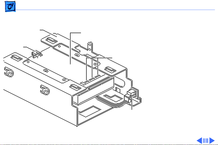
Upgrades Drives in Quadra 900/950 - 1
Drives in Quadra
Hard Drive Carrier
Hard Drive Mechanism
900/950
SCSI Select
Cable
Termination
Resistors
SCSI Select
Switch
There are three general
procedures for preparing
hard drives for Quadra 900/
950 computers:
• Removing the hard drive
mechanism from the
carrier.
• Removing resistors
from the replacement
drives.
• Connecting the SCSI
select cable.
Page 10
Upgrades Drives in Quadra 900/950 - 2
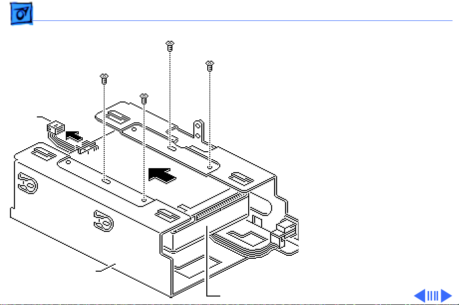
Removing the Hard Drive
1 Disconnect the SCSI
SCSI
Select
Cable
Drive Carrier
Hard Drive
select cable from the
hard drive.
2 Remove the four Phillips
screws.
3 Slide the drive out of the
carrier.
Page 11
Upgrades Drives in Quadra 900/950 - 3
SCSI
Select
Cable
Tab
Terminator
Resistors
Tab
Removing Resistors from the 160 MB Hard Drive
Caution
the terminator resistors can
damage the logic board.
1 Pull up on the tab and
2 Insert the drive in the
3 Attach the SCSI select
: Failure to remove
remove the resistors
from a replacement
160 MB hard drive.
customer’s carrier and
install four screws.
cable tab-up as shown.
Page 12
Upgrades Drives in Quadra 900/950 - 4
Hard Drive
Terminator
Resistors
SCSI Select
Cable
Tab
Removing Resistors from the 230 MB Hard Drive
Caution:
the terminator resistors can
damage the logic board.
1 Using needlenose pliers,
2 Insert the drive in the
3 Attach the SCSI select
Failure to remove
remove the resistors
from a replacement
230 MB drive.
customer’s carrier and
install four screws.
cable as shown.
Page 13

Upgrades Drives in Quadra 900/950 - 5
Hard Drive
SCSI Select
Cable
Terminator
Resistors
Removing Resistors from the 400 MB Hard Drive
Caution:
the terminator resistors can
damage the logic board.
1 Remove the resistors
2 Insert the drive in the
3 Attach the SCSI select
Failure to remove
from a replacement
400 MB drive.
customer’s carrier and
install four screws.
cable with the tab of its
connector facing down.
Page 14

Upgrades Identifying 20SC Rev A & B - 6
Identifying 20SC Rev A & B
No preliminary steps are
required before you begin
this procedure.
Note:
The Hard Drive 20SC
3.5-inch Revision A and
Revision B drives must be
replaced like-for-like.
Identify the revision you
need by matching the
customer’s defective drive
with the replacement drive.
Page 15

Upgrades Identifying 20SC Rev A & B - 7
• Revision A replacement
drives ship in an
internal carrier,
component side up.
• Revision B replacement
Revision A (661-0373)
drives ship in an
internal carrier,
component side down.
Revision B (661-0612)
Page 16

K
Service Source
Additional Procedures
Hard Drives
Page 17

Additional Procedures Carrier Removal - 1
Carrier Removal
No preliminary steps are
required.
Note:
This procedure
applies to hard drive
mechanisms that have been
removed from a computer or
an external hard drive, or to
replacement drive
mechanisms that have not
yet been installed in the
computer.
Caution:
precautions in Bulletins/
Safety.
Review the ESD
Page 18

Additional Procedures Carrier Removal - 2
Ê
Remove the four screws and
lift the carrier from the
hard drive.
Drive
Carrier
Hard
Drive
Replacement Caution:
Be
sure to properly torque the
replacement drive to its
carrier. Failure to do so
could damage the drive. See
“Torque Sequence” in this
chapter.
Note:
For information on
returning defective drives,
see “General Return Info”
and refer to the Parts
chapter in this manual.
Page 19

Additional Procedures Torque Sequence - 3
Torque Sequence
Hard
Drive
Drive
Carrier
Torque Driver
No preliminary steps are
required before you begin
this procedure.
Note
: This procedure applies
to hard drive mechanisms
that have been removed from
a computer or an external
hard drive, or to
replacement drive
mechanisms that have not
yet been installed in the
computer.
Using a torque driver,
Page 20

Additional Procedures Torque Sequence - 4
tighten the screws in the
order shown. Torque the
screws with driver to
8.0-inch pounds.
Note:
The torque sequence
is the same for all types of
drives and carriers. The
Apple torque driver is
preset to 8 in/lbs.
Page 21

Additional Procedures Modifying 5.25-Inch Drives - 5
Modifying 5.25-
External
Hard Drives
Only
Inch Drives
No preliminary steps are
required before you begin
this procedure.
This section describes
procedures for modifying
5.25-inch replacement
hard drives that are
qualified for external hard
drives. To learn whether a
replacement drive is a
qualified external drive,
refer to compatibility
information in the Service
Source parts database.
Page 22

Additional Procedures Modifying 5.25-Inch Drives - 6
Note:
The 20 MB and
160 MB external 5.25-inch
replacement hard drives
ship prepared for external
drives. You must modify
other replacement hard
drives for use in external
hard drives.
Ê
Page 23

Additional Procedures Modifying 5.25-Inch Drives - 7
1 Remove the four
mounting screws and
carrier from the 5.25inch service
replacement hard drive.
2 Disconnect the power
Carrier
cable (if attached) from
the replacement drive.
Ê
Power Cable
Page 24

Additional Procedures Modifying 5.25-Inch Drives - 8
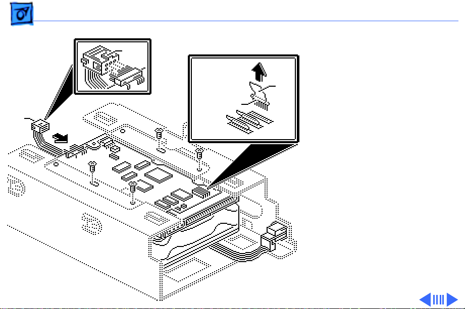
3 Disconnect the resistors
from the component side
Terminator
Resistors
of the replacement drive.
Use needlenose pliers
and pull the resistors
straight up.
4
Replacement Note:
Be
sure that the tab on the
SCSI Select Cable
Jumpers
SCSI select cable
connector points toward
the hard drive data cable.
Connect the SCSI select
cable to the three pairs
of pins on the component
side of the drive. Leave
the black jumpers on the
other pins.
Page 25

Additional Procedures Modifying 5.25-Inch Drives - 9
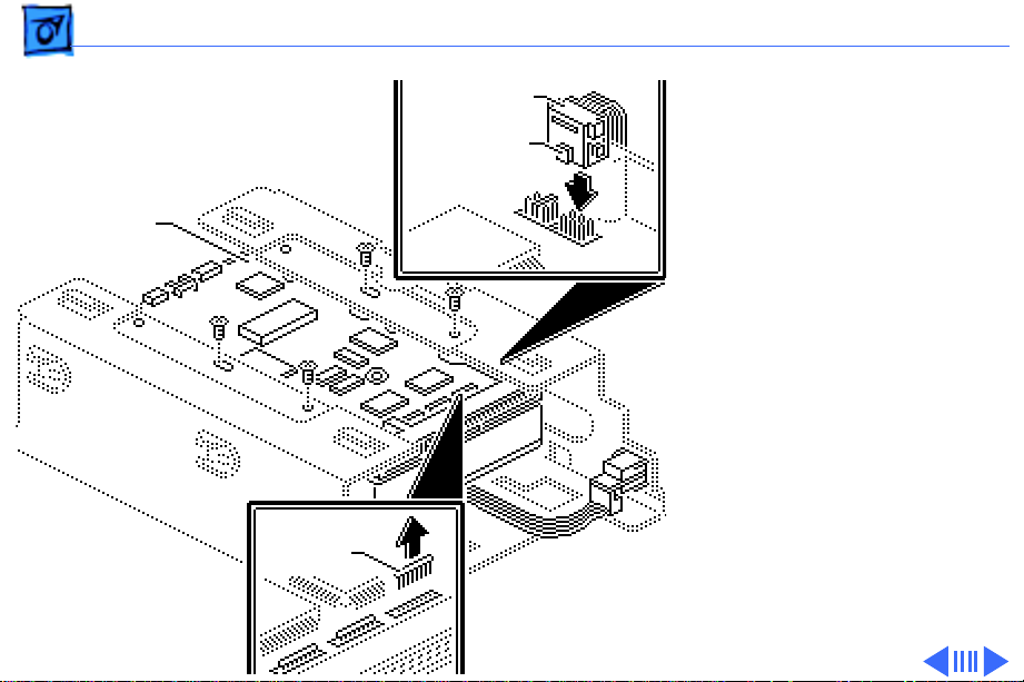
5 Connect the LED cable
connector from the
customer’s external
carrier to the component
side of the replacement
drive.
6 Attach the reconfigured
replacement hard drive
to the customer’s
LED
Cable
external carrier with
the four screws.
Note:
For information
on returning defective
drives, see “General
Return Info” and refer
to the Service Source
parts database.
Page 26

Additional Procedures Modifying 3.5-Inch Drives - 10
External Drives Only
Modifying 3.5Inch Drives
No preliminary steps are
required before you begin
this procedure.
This section describes
procedures for modifying
3.5-inch replacement hard
drives that are qualified for
external hard drives. To
learn whether a replacement
drive is a qualified external
drive, refer to compatibility
information in the Service
Source parts database.
Page 27

Additional Procedures Modifying 3.5-Inch Drives - 11
Note:
The External 20 MB
SCSI Rev A replacement hard
drive ships prepared for use
in external hard drives. You
must modify other
replacement hard drives for
use in external hard drives.
Ê
Page 28

Additional Procedures Modifying 3.5-Inch Drives - 12
1 Remove the 3.5-inch
replacement hard drive
from its carrier.
Power Cable
Terminator Resistors
2 Disconnect the power
cable (if attached) from
the replacement drive.
3
Note:
The location of the
terminator resistors
may differ among drives.
Disconnect the three
terminator resistors
from the component side
of the replacement drive.
Use needlenose pliers, if
necessary.
Page 29

Additional Procedures Modifying 3.5-Inch Drives - 13
4
Important:
You must
connect the customer’s
SCSI select cable to six
Tab
SCSI
Select Cable
Select Cable
SCSI
Tab
unkeyed pins on the
controller board. Be
aware that SCSI select
cable connectors differ
among drives in both
design and location.
For SCSI select cable
connectors located on the
edge of the drive controller
board:
• Remove any black
jumpers that may be
installed on the outside
pins.
Page 30

Additional Procedures Modifying 3.5-Inch Drives - 14
• Face the tab up and attach
the SCSI cable connector.
SCSI
Select
Cable
Tab
For SCSI select cable
connectors located on the
surface of the controller
board:
• Face the SCSI cable
connector tab toward the
center of the drive.
• Attach the connector to
the six pins closest to the
50-pin SCSI connector.
Important:
Combinations
of SCSI select
connectors and cables
vary. To verify the
proper position of the
Page 31

Additional Procedures Modifying 3.5-Inch Drives - 15
SCSI select cable
connector, connect the
drive to a known-good
Macintosh and choose
Info
from the Finder’s
File menu. If
displays the wrong SCSI
ID or drive name,
reverse the tab of the
SCSI select cable
connector.
Ê
Get Info
Get
Page 32

Additional Procedures Modifying 3.5-Inch Drives - 16
External Carrier
Customer's
LED
Cable
5 Connect the LED cable
connector from the
customer’s external
carrier to the component
side of the replacement
drive.
6 Install the reconfigured
replacement hard drive
in the customer’s
external carrier.
Note:
For information on
returning defective
drives, see “General
Return Info” and refer
to the Service Source
parts database.
Page 33

Additional Procedures General Return Information - 17
General Return Information
No preliminary steps are
required before you begin
this procedure.
Note
: You must return a
defective hard drive to Apple
without the carrier and
cables.
Note:
For specific return
requirements, refer to the
Service Source parts
database.
Ê
Page 34

Additional Procedures General Return Information - 18
Each drive has four cables
that need to be removed
before the hard drive is
LED Cable
SCSI Select Cable
Hard Drive
Data Cable
returned. They are
• Power cable
• Hard drive data cable
• SCSI select switch cable
• LED cable
Note:
For specific return
requirements, refer to the
Service Source parts
database.
Power Cable
Page 35

Additional Procedures Setting SCSI ID - 19
Setting SCSI ID
No preliminary steps are
SCSI Select Pins
required before you begin
this procedure.
1 To set the SCSI ID, locate
the drive’s six SCSI
select pins.
Note:
The location of the
SCSI select pins varies
among drives.
Generally, the group of
six (occasionally eight)
pins is on the top or side
of the printed circuit
board.
Page 36

Additional Procedures Setting SCSI ID - 20
Note:
If you are
installing the drive in a
docking station, such as
the DuoDock, Apple
recommends you change
the SCSI ID to 1. If you
are installing the drive
mechanism in an
external drive case,
Apple recommends you
change the SCSI ID to any
number from 2 to 6.
Ê
Page 37

Additional Procedures Setting SCSI ID - 21
2 Place jumpers on the
pairs of pins as shown in
the table below.
Note
: In the following
table, the SCSI ID
numbers are labeled
across the top and the
pin numbers are labeled
on the side. (The pin
pairs may be labeled
using either the A0-A1A2 pin number
convention or the E1E2-E3 convention. Some
pin pairs may not be
labeled.) The letter “J”
Page 38

Additional Procedures Setting SCSI ID - 22
indicates a jumper.
01234567
A0/E1 - J - J - J - J
A0/E2 - - J J - - J J
A0/E3 ----JJJJ
 Loading...