

Page 1
Service Source
Power Mac G4 Cube
Updated June 2, 2003
© 2002 Apple Computer, Inc. All rights reserved.
Page 2

Service Source
Take Apart
Power Mac G4 Cube
© 2002 Apple Computer, Inc. All rights reserved.
Page 3

General Instructions
Tools
The following tools are recommended for the Take Apart procedures:
• ESD wriststrap and mat
• Flat -blade screwdriver
• Magnetized Phillips screwdriver
• Torx T8 screwdriver
• Torx T10 screwdriver
• Pliers
• Jeweler’s Phillips screwdriver
• Black stick (or other nonconductive plastic or nylon tool)
Note:
To organize the screws you remove from the assembly, use a tray with divided
compartments (such as a plastic ice cube tray).
Serial Number Location
In this computer, the product serial number is located on the base near the computer
latch.
General Instructions
Power Mac G4 Cube Take Apart -
1
Page 4
Computer Enclosure
Tools
No tools are required for this procedure.
Preliminary Steps
Before you begin, turn off the computer.
Procedure
Warning: Always turn off the computer before opening it to avoid damaging its
internal components.
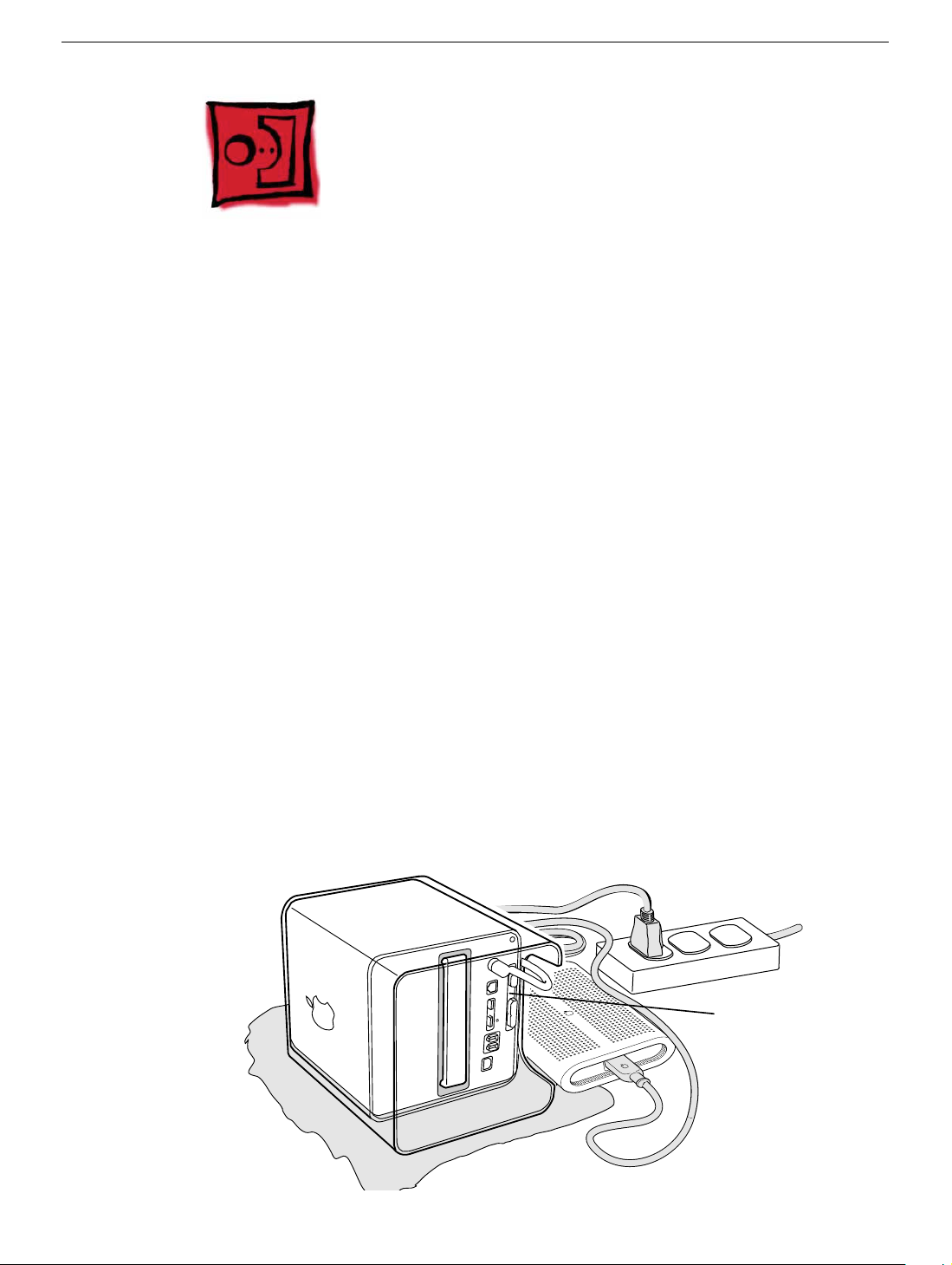
1. Place the computer on a clean, flat surface.
2. Shut down the computer, and w ait five min utes for the computer’ s internal components
to cool down.
3. Unplug all cables from the computer except the power cord.
Note:
If you have never plugged in the computer, connect the computer’s
power cord and plug it in.
4. Turn the computer on its side on a soft, clean cloth, and ground yourself by touching
the bare metal between the video ports.
Touch
Bare
Metal
2 -
Power Mac G4 Cube Take Apart
Computer Enclosure
Page 5
Important:
To avoid electrostatic discharge, always ground yourself by
touching the bare metal before you touch any parts or install any components
inside the computer. To avoid static electricity building back up in your body,
do not walk around the room until you have completed the installation and
closed the computer.
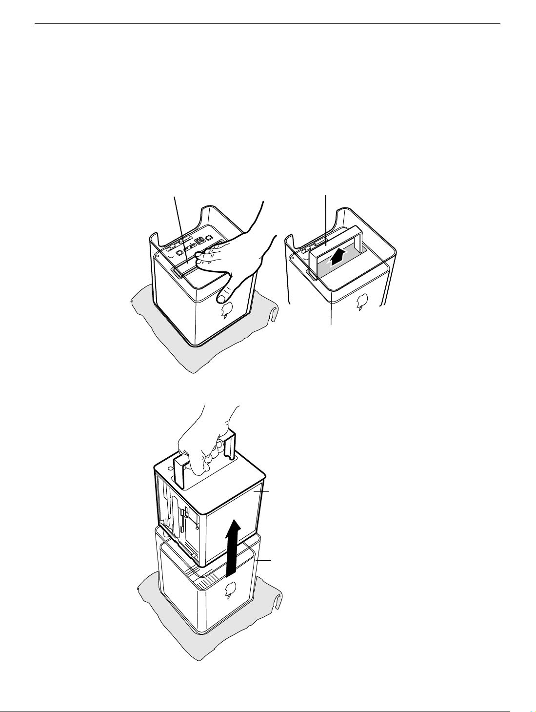
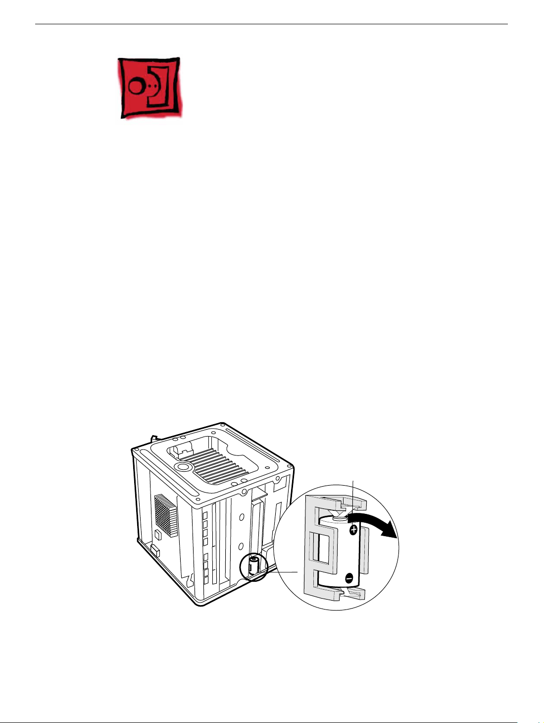
5. Unplug the power cord.
6. Turn the computer upside down, and push down on the latch to release it. Allow the
latch to extend completely.
Latch
Extended Latch
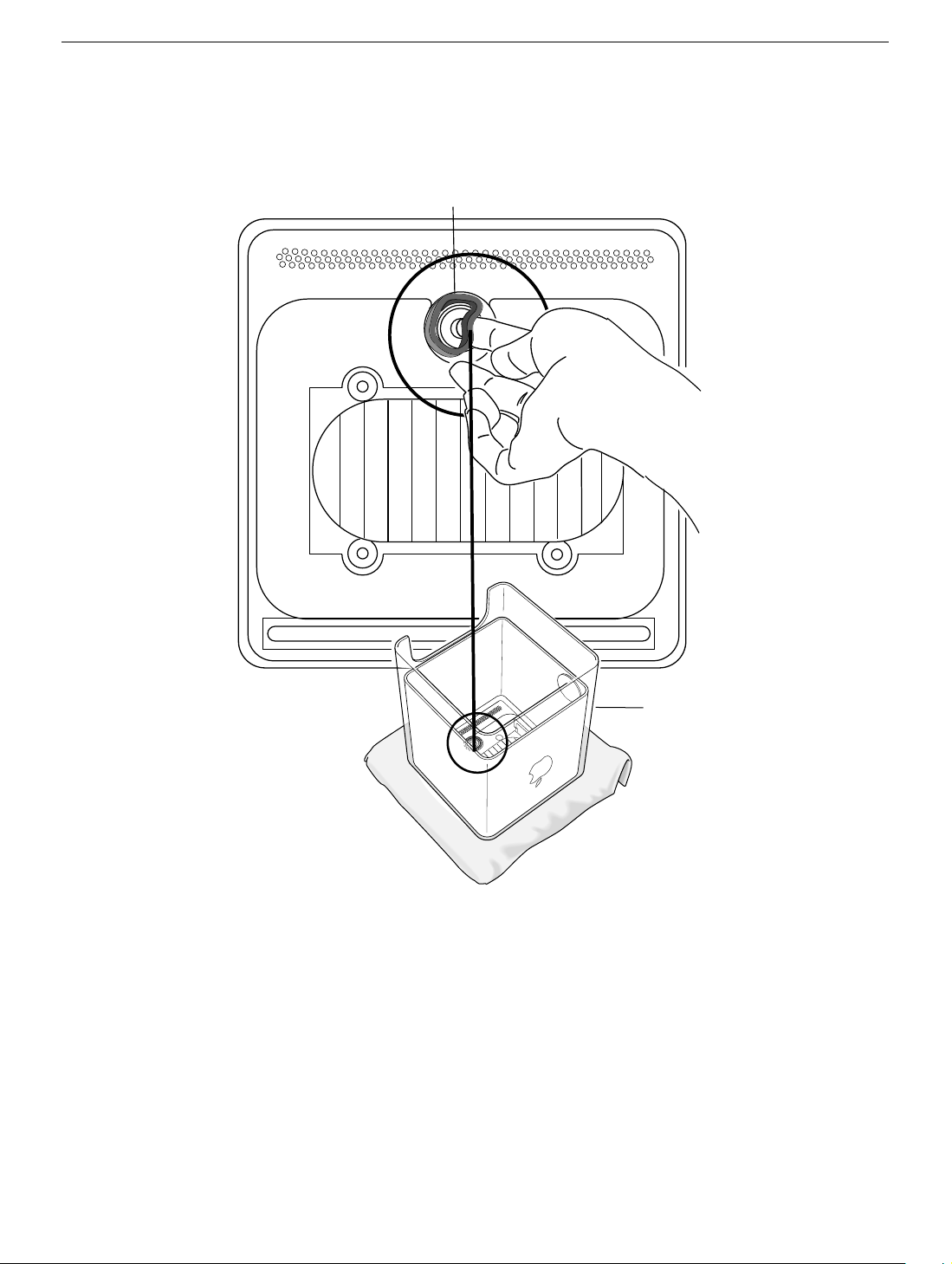
7. Gently pull the core from the computer enclosure and place the core on a soft cloth.
Computer Enclosure
Core
Enclosure
Power Mac G4 Cube Take Apart -
3
Page 6
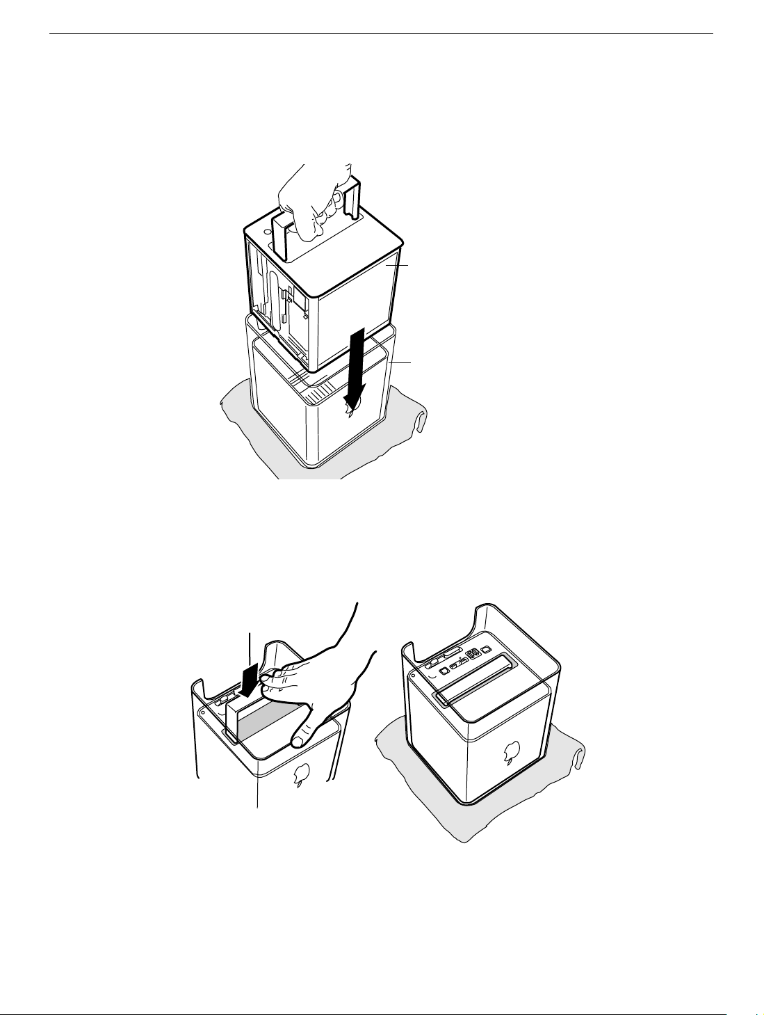
8. Holding the core by the latch, insert the core into the replacement enclosure.
Note:
The core fits into the enclosure only one way. Position the core so the ports
are toward the back of the enclosure.
Core
Enclosure
9. With a flat hand, press down on the latch until it locks into place. Firmly press the core
to ensure it is fully secured within the enclosure.
Important:
Do not lift or carry your computer by the core latch. The enclosure could
fall off the core and be damaged.
Latch
10. Turn the computer upright and reconnect all cables.
Warning: Never turn on the computer unless all of its internal and external
parts are in place and it is closed. Operating the computer when it is open or
missing parts can damage the computer or cause injury.
4 -
Power Mac G4 Cube Take Apart
Computer Enclosure
Page 7
Battery
Tools
No tools are required for this procedure.
Preliminary Steps
Before you begin, remove the computer core from the enclosure.
Procedure
1. Note the orientation of the installed battery’s positive (+) end. (Positive and negative
signs are also marked on the battery holder.)
2. Use your finger to gently pry the battery out of the holder and out of the computer.
Warning: Batteries contain chemicals, some of which may be harmful to the
environment. Please dispose of used batteries according to your local
environmental laws and guidelines. Do not return used batteries to Apple.
Battery
Positive End
Battery
3. Insert the replacement battery into the holder, making sure the battery’s positive and
negative signs align with those on the holder.
Warning: Installing the battery incorrectly may cause an explosion. Be sure the
battery’s positive and negative poles are correctly oriented in the holder. Use
Power Mac G4 Cube Take Apart -
5
Page 8

only the battery supplied.
4. Reassemble and test the computer.
Warning: Never turn on the computer unless all of its internal and external
parts are in place and it is closed. Operating the computer when it is open or
missing parts can damage the computer or cause injury.
6 -
Power Mac G4 Cube Take Apart
Battery
Page 9

Power Button Gasket
Tools
No tools are required for this procedure.
Preliminary Steps
Before you begin, remove the computer core from the enclosure.
Power Button Gasket
Power Mac G4 Cube Take Apart -
7
Page 10
Procedure
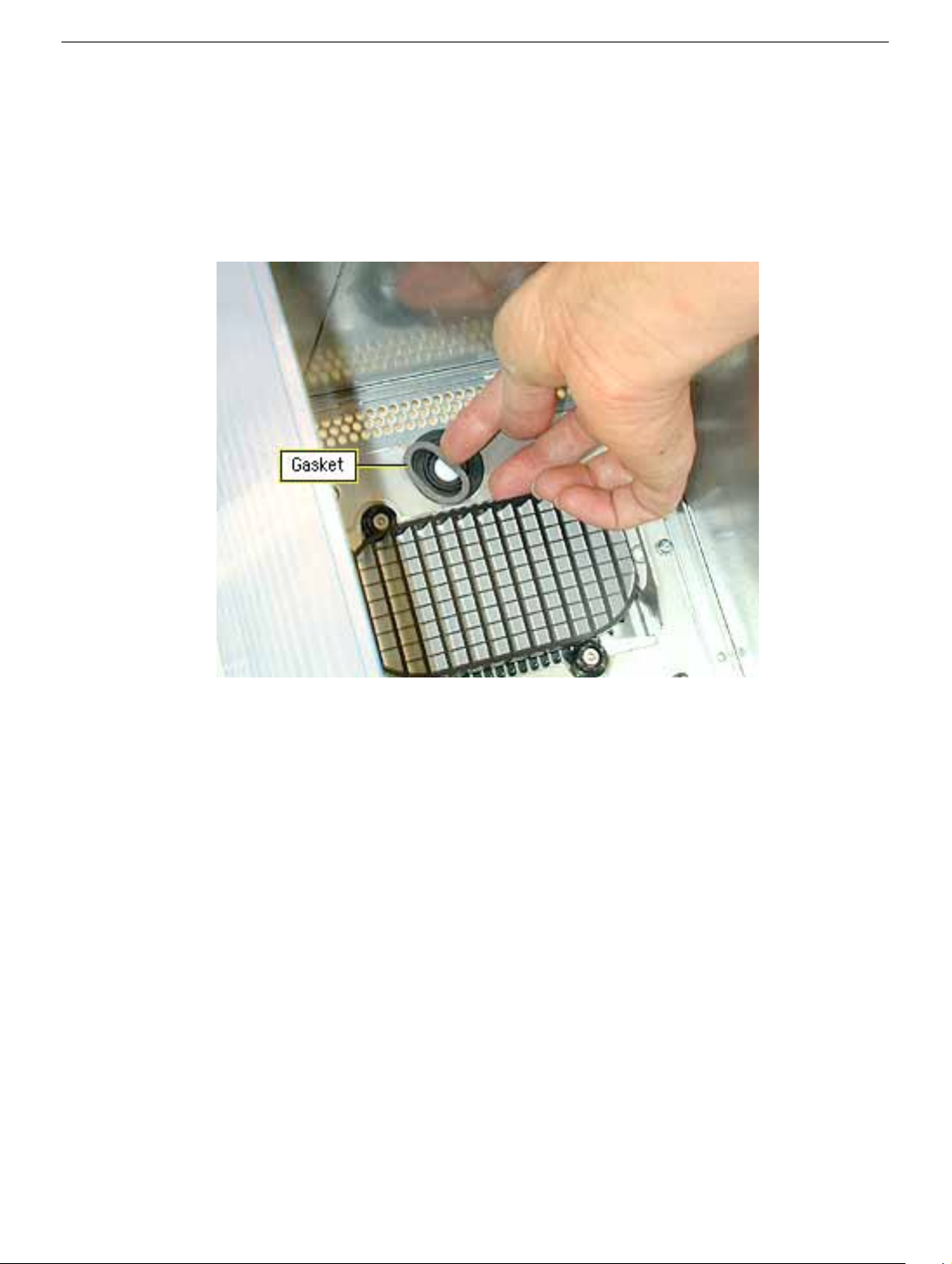
1. Place your hand in the computer enclosure and lift out the installed gasket.
Gasket
Enclosure
2. Insert the replacement power button gasket into the recessed area that encircles the
power button.
3. Press the gasket into place to ensure that it is secure.
4. Reassemble and test the computer.
Warning: Never turn on the computer unless all of its internal and external
parts are in place and it is closed. Operating the computer when it is open or
missing parts can damage the computer or cause injury.
8 -
Power Mac G4 Cube Take Apart
Power Button Gasket
Page 11
AirPort Card
Tools
No tools are required for this procedure.
Preliminary Steps
Before you begin, remove the computer core from the enclosure.
Procedure
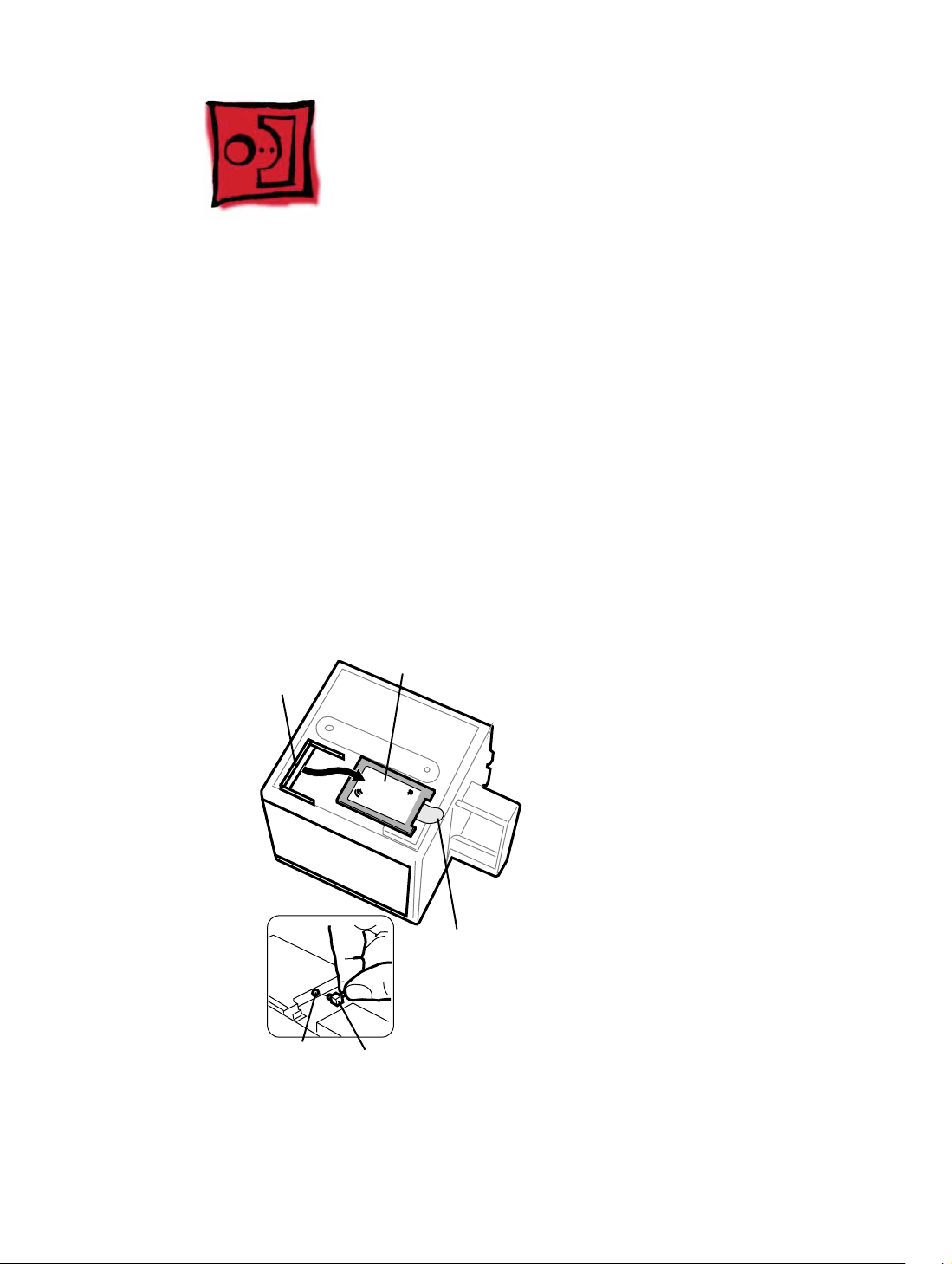
1. Disconnect the coaxial antenna cable from the port on the end of the AirPort Card.
2. Pull the plastic tab on the end of the AirPort Card to release the AirPort Card from the
PCI card connector.
AirPort Card
Connector
AirPort Card
AirPort
Pull Tab
Antenna Port on
AirPort Card
3. Insert the replacement AirPort Card through the opening in the PCI card guide and
into the connector on the logic board.
Antenna
Cable
AirPort Card
4 Carefully attach the coaxial antenna cable to the port on the end of the AirPort Card.
Power Mac G4 Cube Take Apart -
9
Page 12

Note:
The antenna cable might be stowed on the side of the PCI card guide. Do not
bend or crimp the cable tightly.
5. Reassemble and test the computer.
Warning: Never turn on the computer unless all of its internal and external
parts are in place and it is closed. Operating the computer when it is open or
missing parts can damage the computer or cause injury.
10 -
Power Mac G4 Cube Take Apart
AirPort Card
Page 13
Memory (DRAM DIMM)
Tools
No tools are required for this procedure.
Preliminary Steps
Before you begin, remove the computer core from the enclosure.
Procedure
1. If provided, attach the grounding wrist strap included with the replacement memory.
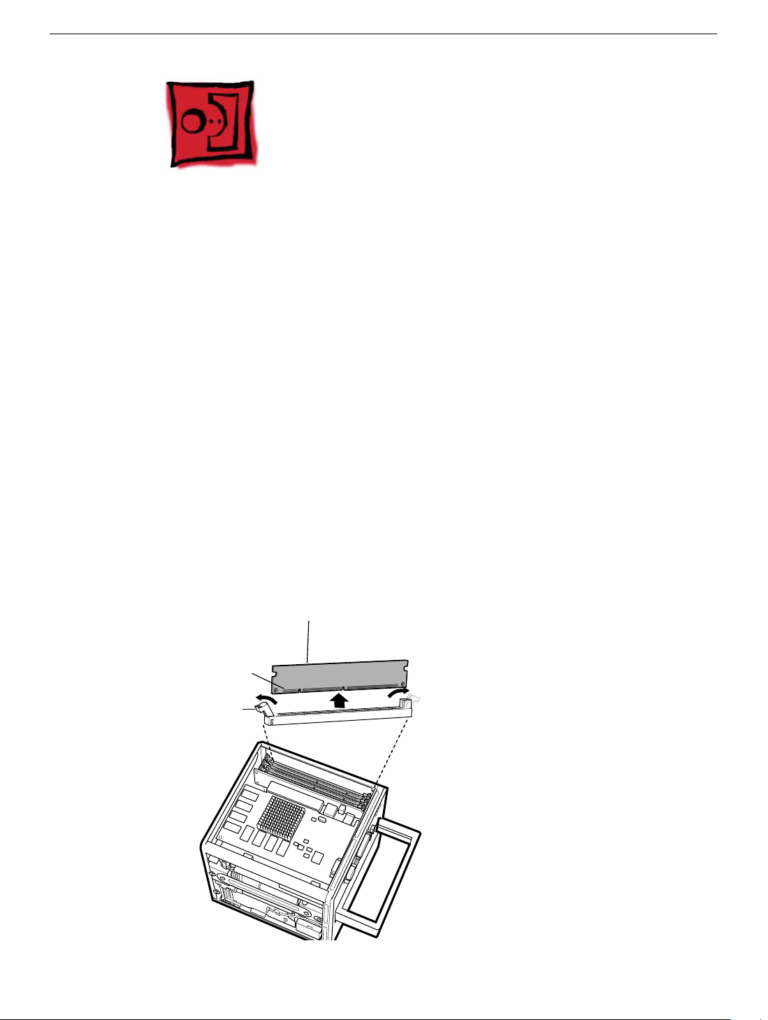
2. Push down the ejectors on the slot of the DIMM you want to replace.
Note: The slot might have one or two ejectors.
3. Lift the DIMM out of the computer.
Warning:
the DIMM only by the edges.
Connectors
Ejector
When removing or installing the DIMM, do not touch its connectors. Handle
DRAM DIMM
DRAM Slot
Memory (DRAM DIMM)
Power Mac G4 Cube Take Apart -
11
Page 14

4. Remove the replacement DIMM from its static-proof bag, taking care not to touch the
connectors or chips.
5. Align the replacement DIMM in the DIMM slot. Press the DIMM down firmly until you
feel it securely attach to the slot, and the ejectors lock it into place.
6. Reassemble and test the computer.
Warning: Never turn on the computer unless all of its internal and external
parts are in place and it is closed. Operating the computer when it is open or
missing parts can damage the computer or cause injury.
12 -
Power Mac G4 Cube Take Apart
Memory (DRAM DIMM)
Page 15
ATA Hard Drive
Tools
This procedure requires the following tools:
• Flat-blade screwdriver
• Torx T8 screwdriver
• Phillips screwdriver
Preliminary Steps
Before you begin, remove the following:
• Computer core from enclosure
• AirPort Card, if installed
Procedure
1. Press and hold the door latch, and then open the AirPort shield door.
.
Door Latch
ATA Hard Drive
Power Mac G4 Cube Take Apart -
13
Page 16
2. With the AirPort shield door open, pull the tab to disconnect the ATA ribbon cable
connector from the hard drive.
3. Disconnect the power cable connector from the hard drive. (You might need to use a
flat-blade screwdriver to pry up and loosen the connector.)
Pull Tab
Connector
Connector
Door
14 -
Power Mac G4 Cube Take Apart
ATA Hard Drive
Page 17
4. Push in the core latch, and reposition the computer chassis so you can access the
heatsink and hard drive.
5. Loosen, but do not remove, the three captive screws at the heatsink.
6. Lift up the loosened heatsink, and slide the hard drive out of the carrier.
Screws
Heatsink
Hard Drive
7. Position the replacement drive on the driv e carrier so that the ribbon cable and power
cable connectors align with the slots at the end of the carrier.
8. Lift up the heatsink, and slide in the drive.
9. Align the heatsink fins to the opposite heatsink fins. Tighten the three captive screws.
ATA Hard Drive
Power Mac G4 Cube Take Apart -
15
Page 18
10. Reconnect the power cable connector and the ATA ribbon cable connector to the
drive.
Pull Tab
Connector
Connector
Door
11. Close the AirPort shield door, and press it down so the door latch engages.
Door Latch
12. Reinstall the AirPort Card, if applicable.
13. Reassemble and test the computer.
Warning: Never turn on the computer unless all of its internal and external
parts are in place and it is closed. Operating the computer when it is open or
missing parts can damage the computer or cause injury.
16 -
Power Mac G4 Cube Take Apart
ATA Hard Drive
Page 19
Plastic Shell from Enclosure
Tools
This procedure requires the following tools:
• Phillips screwdriver
• Torx T8 screwdriver
Preliminary Steps
Before you begin, remove the computer core from the enclosure.
Procedure
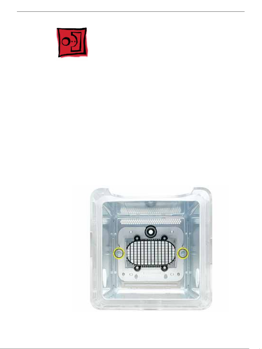
1. Looking into the computer enclosure, remove the two Phillips screws near the
sides of the enclosure.
Plastic Shell from Enclosure
Power Mac G4 Cube Take Apart -
17
Page 20
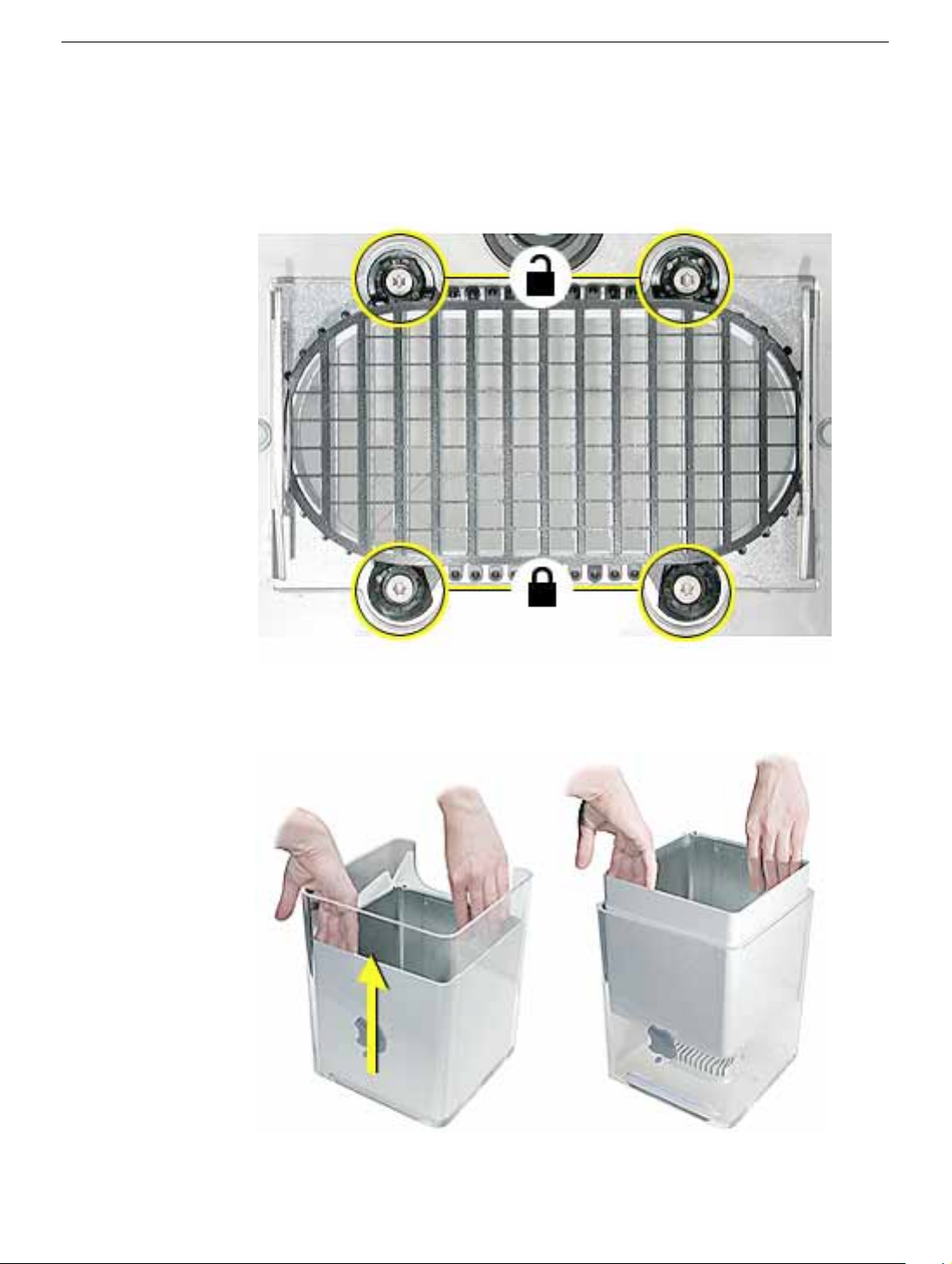
2. Loosen—but do not remove—the four Torx screws at the grill.
3. Notice that each screw has a grommet, and the round base of the grommet has
one flat edge. To unlock the enclosure liner, turn the grommet so the flat edge
is flush with the side of the grill. Repeat for all grommets.
4. To protect the outside surface of the metal liner, place your hands inside the
liner to lift it straight up and out of the shell.
18 -
Power Mac G4 Cube Take Apart
Plastic Shell from Enclosure
Page 21
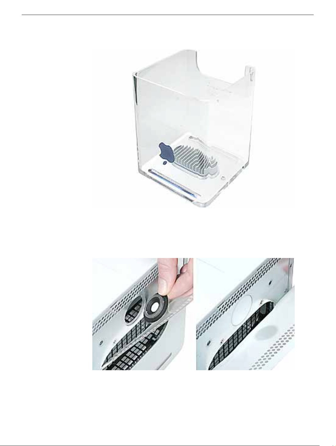
5. Lift the plastic shell off of the grill.
6. Position the replacement plastic shell over the grill.
7. Before installing the liner in the shell, check that the power button is in place. If the
power button gasket assembly has slipped out of the socket, install it under the gray
cover sheet. Hold it in place as you slide the liner in the replacement shell.
8. Turn the grommets so that a corner of their flat edge locks the grill into place.
Hold each grommet in that position as you tighten the Torx screws.
9. Install the two Phillips screws.
Plastic Shell from Enclosure
Power Mac G4 Cube Take Apart -
19
Page 22
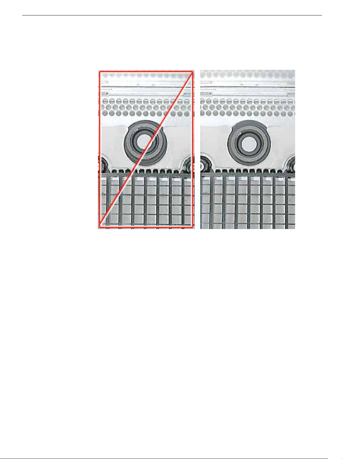
10.
Caution:
the computer might not power up. Make sure the power button gasket assembly is
level and centered in place.
If the power button gasket assembly is not centered correctly in the shell,
11. Reassemble and test the computer.
Warning: Never turn on the computer unless all of its internal and external
parts are in place and it is closed. Operating the computer when it is open or
missing parts can damage the computer or cause injury.
20 -
Power Mac G4 Cube Take Apart
Plastic Shell from Enclosure
Page 23
Top Plate Assembly with Power Button Gasket
Tools
The only tool required for this procedure is a Torx T10 screwdriver.
Preliminary Steps
Before you begin, remove the computer core from the enclosure.
Procedure
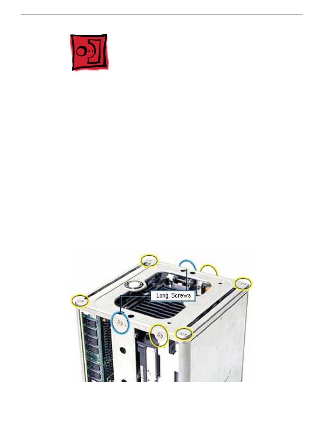
1. Press the latch in, and turn over the core so the power button faces up.
2. Remove the four corner screws that secure the top plate to the four vertical posts.
3. Remove the four screws on the two sides. (The two screws that align with the vertical
plates are much longer than the other screws.)
Top Plate Assembly with Power Button Gasket
Power Mac G4 Cube Take Apart -
21
Page 24
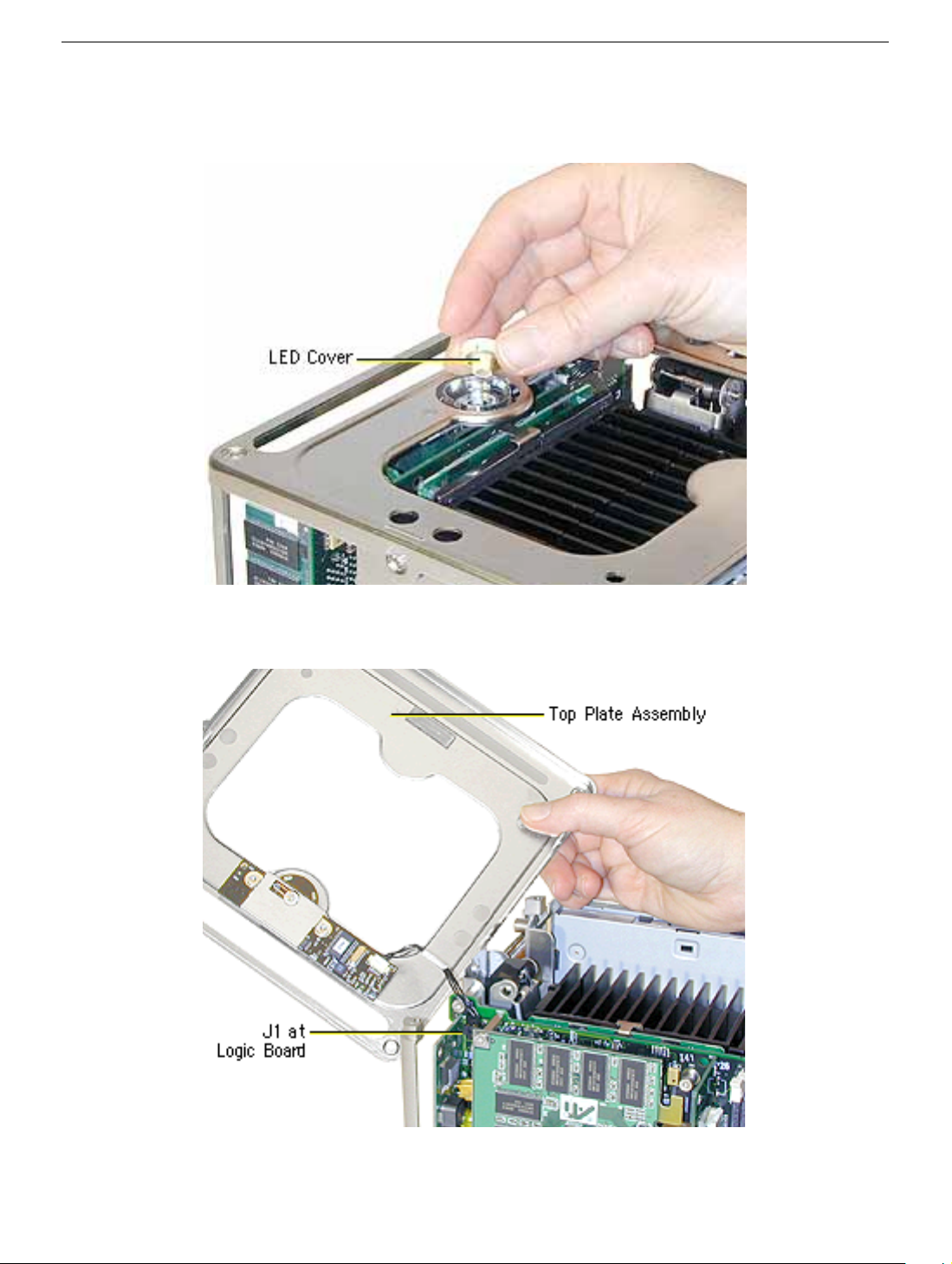
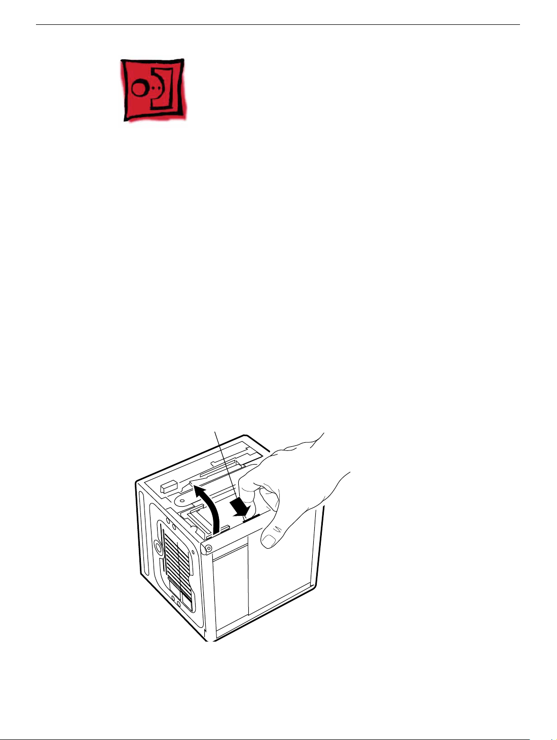
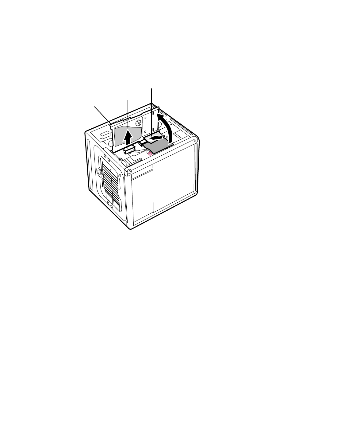
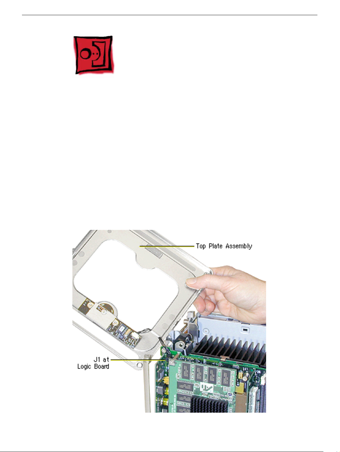
4. Lift out the LED cover that is fitted over the power button LED. Set the LED cover
aside for installation on the new top plate assembly.
5. Carefully lift up the top plate and disconnect the keyed connector (J1 on the logic
board).
22 - Power Mac G4 Cube Take Apart
Top Plate Assembly with Power Button Gasket
Page 25
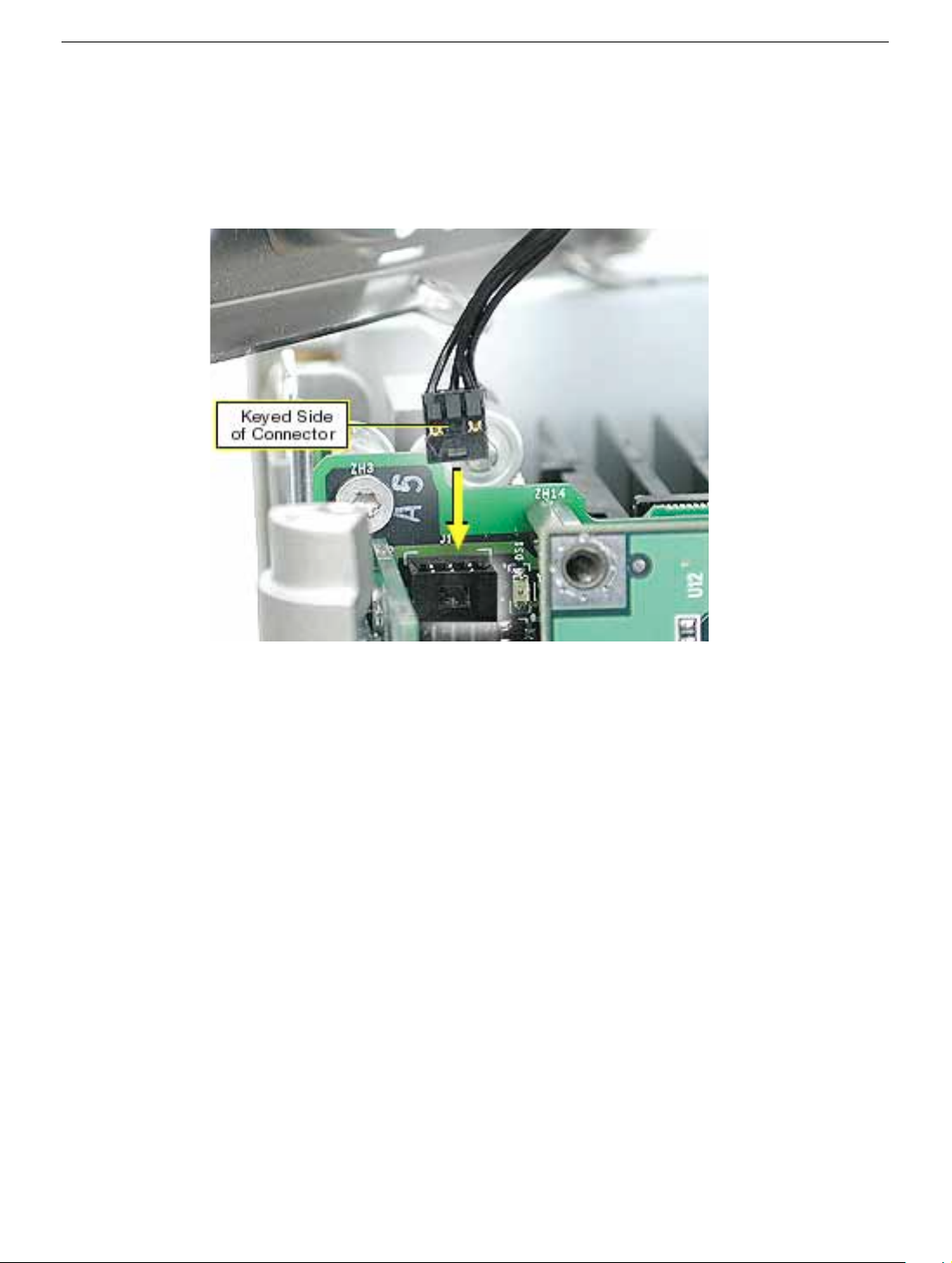
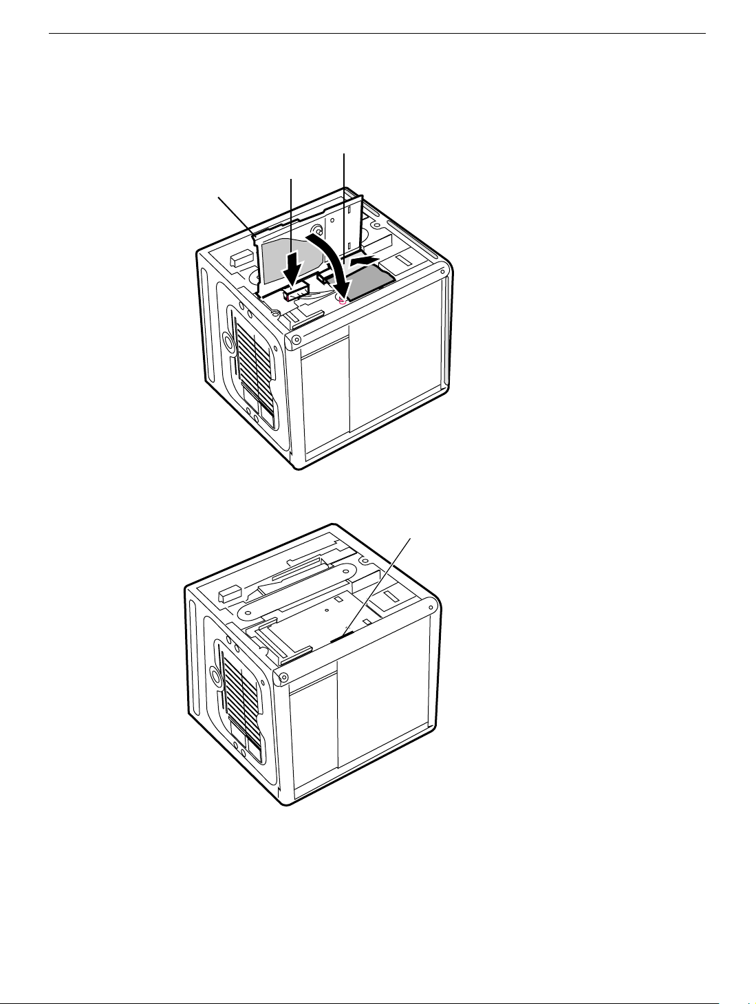
6. With the replacement top plate assembly in hand, connect the cable from the top plate
to the J1 connector on the logic board.
Warning: To prevent damage to the power board, ensure the keyed connector fits
into the J1 connector as shown.
Top Plate Assembly with Power Button Gasket
Power Mac G4 Cube Take Apart - 23
Page 26
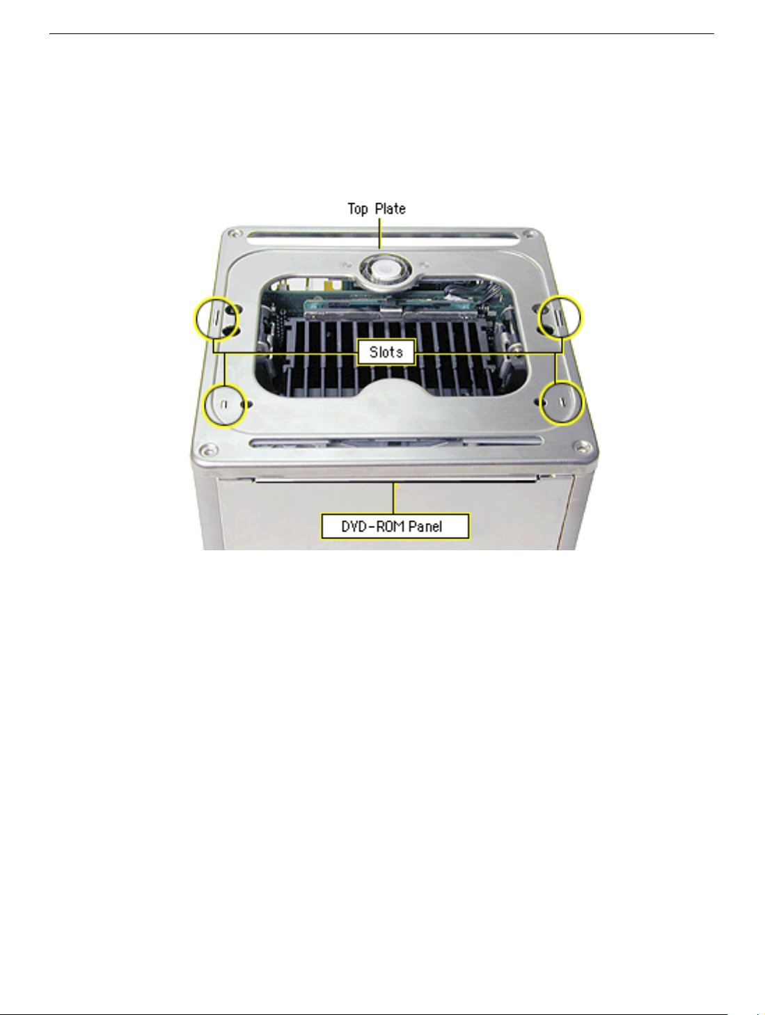
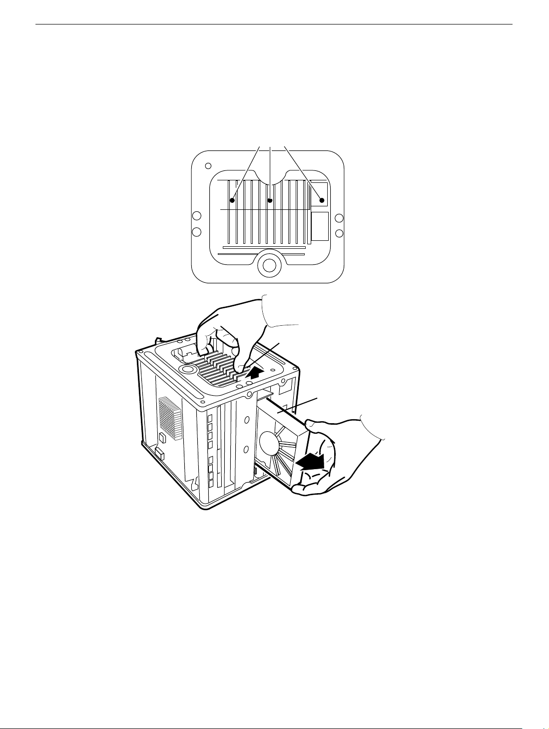
7. Install the LED cover over the power button LED on the replacement top plate
assembly.
8. Position the top plate assembly over the core. Ensure that the four metal tabs align
with the four slots in the top plate, and the DVD-ROM panel tucks in under the lip of
the top plate.
9. Starting with the four corner screws, secure the top plate to the core with all eight
screws.
24 - Power Mac G4 Cube Take Apart
Top Plate Assembly with Power Button Gasket
Page 27
10. Locate the power button gasket that came with the new top plate assembly. Install the
gasket inside the enclosure as follows:
• Place your hand in the enclosure and lift out the installed gasket.
• Insert the new power button gasket into the recessed area that encircles the power
button.
• Press the gasket into place to make sure that it is secure.
11. Reassemble and test the computer.
Warning: Never turn on the computer unless all of its internal and external
parts are in place and it is closed. Operating the computer when it is open or
missing parts can damage the computer or cause injury.
Top Plate Assembly with Power Button Gasket
Power Mac G4 Cube Take Apart - 25
Page 28
Top Plate Cable
Tools
The only tool required for this procedure is a Torx T10 screwdriver.
Preliminary Steps
Before you begin, remove the following:
• Computer core from enclosure
• Top plate assembly
Procedure
1. Lift up the top plate and disconnect the keyed connector (J1 on the logic board).
26 - Power Mac G4 Cube Take Apart
Top Plate Cable
Page 29
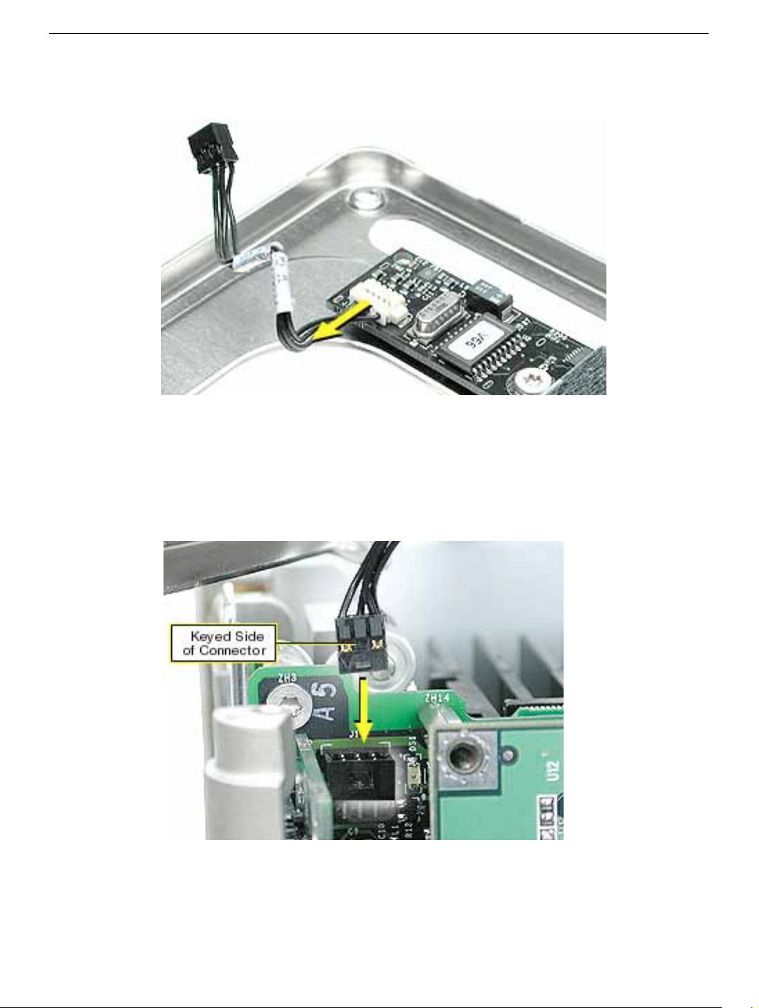
2. Disconnect the cable from the power board.
3. Connect the replacement cable to the power board on the top plate.
4. Connect the other end of the replacement cable to the J1 connector on the logic
board.
Warning: To prevent damage to the power board, ensure the keyed connector fits
into the J1 connector as shown.
5. Reassemble and test the computer.
Warning: Never turn on the computer unless all of its internal and external
parts are in place and it is closed. Operating the computer when it is open or
missing parts can damage the computer or cause injury.
Top Plate Cable
Power Mac G4 Cube Take Apart - 27
Page 30
Power Button Board
Tools
The only tool required for this procedure is a Torx T10 screwdriver.
Preliminary Steps
Before you begin, remove the following:
• Computer core from enclosure
• Top plate assembly
Procedure
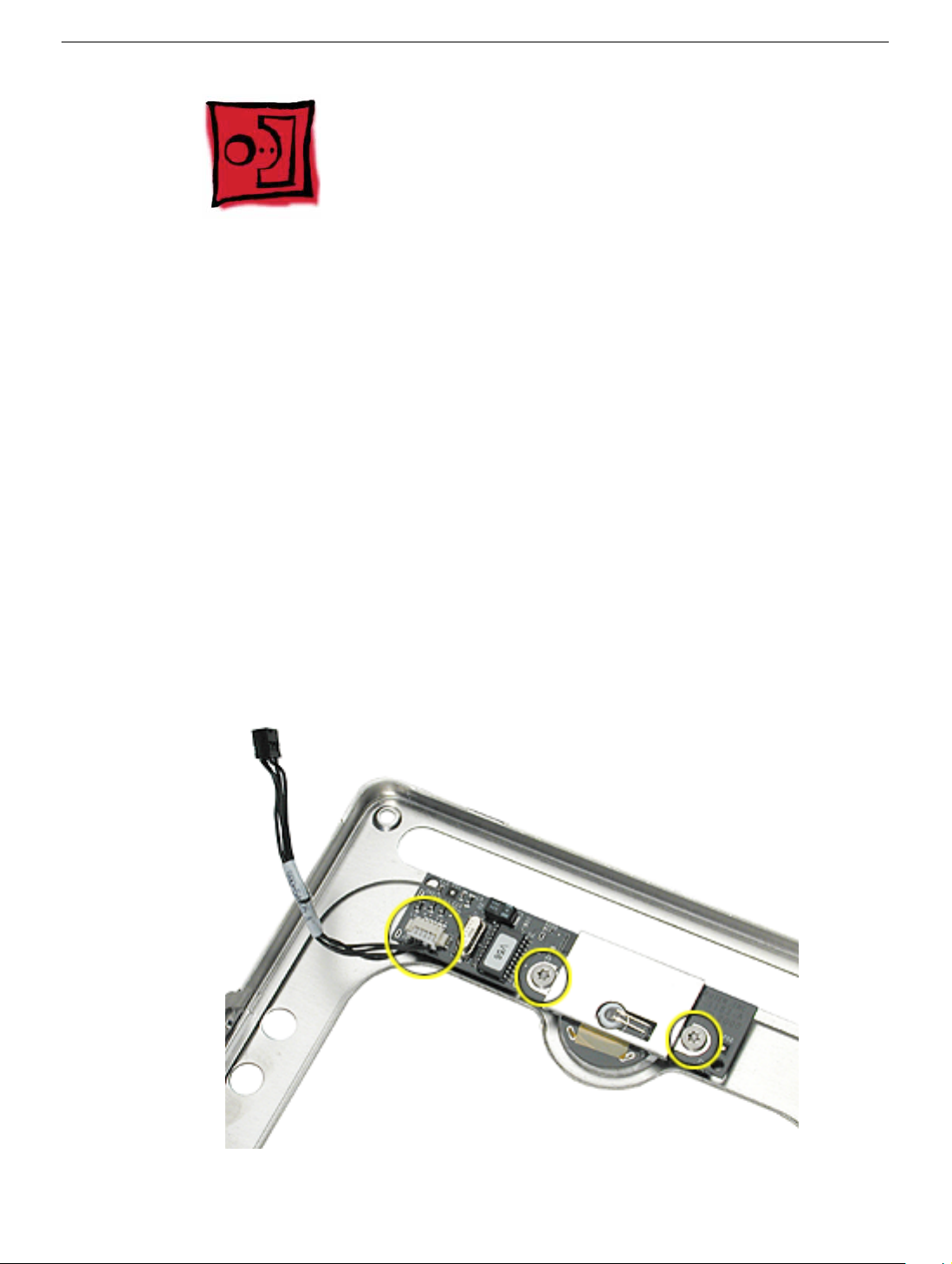
1. Disconnect the top plate cable from the power button board.
2. Remove the two screws from the board.
3. Lift the board off of the top plate.
28 - Power Mac G4 Cube Take Apart
Power Button Board
Page 31

4. Make sure you place the proximity switch plate over the replacement power button
board before installing the board on the top plate.
5. Reassemble and test the computer.
Warning: Never turn on the computer unless all of its internal and external
parts are in place and it is closed. Operating the computer when it is open or
missing parts can damage the computer or cause injury.
Power Button Board
Power Mac G4 Cube Take Apart - 29
Page 32

Support Bars
Tools
No tools are required for this procedure.
Preliminary Steps
Before you begin, remove the following:
• Computer core from enclosure
• Top plate assembly
Procedure
1. Place the computer core on its base so the heatsink faces up.
2. Grasp the first support bar, and pull it up to release it from the chassis. Repeat for the
other three support bars.
30 - Power Mac G4 Cube Take Apart
Support Bars
Page 33

3. Install the replacement support bars and press down until they click into place.
4. Reassemble and test the computer.
Warning: Never turn on the computer unless all of its internal and external
parts are in place and it is closed. Operating the computer when it is open or
missing parts can damage the computer or cause injury.
Support Bars
Power Mac G4 Cube Take Apart - 31
Page 34

AirPort Antenna
Tools
The only tool required for this procedure is a black stick (or other nonconductive nylon or
plastic tool).
Preliminary Steps
Before you begin, remove the following:
• Computer core from enclosure
• Top plate assembly
Procedure
1. Place the computer core on its base so the CD-ROM panel faces you. Remove the
panel.
2. Remove the AirPort antenna cable from the AirPort door (or from the AirPort Card, if
installed).
32 - Power Mac G4 Cube Take Apart
AirPort Antenna
Page 35

3. Pull up and remove the two support bars that are closest to the CD-ROM drive.
4. Pull up on the antenna box to disconnect it from the chassis.
AirPort Antenna
Power Mac G4 Cube Take Apart - 33
Page 36

5. Route the antenna cable out of the chassis channel.
34 - Power Mac G4 Cube Take Apart
AirPort Antenna
Page 37

6. Gently guide the antenna box and cable out of the chassis.
Note: When replacing the antenna cable, use a black stick to tuck the cable under
the drive and connectors.
7. Remove the antenna box from the other side of the CD-ROM drive.
AirPort Antenna
Power Mac G4 Cube Take Apart - 35
Page 38

8. Install the replacement AirPort antenna cable, and reassemble and test the computer.
Warning: Never turn on the computer unless all of its internal and external
parts are in place and it is closed. Operating the computer when it is open or
missing parts can damage the computer or cause injury.
9. When installing the panel, make sure that all four tabs engage and no cables get
caught.
10. Important: Ensure the panel tucks into the computer chassis.
36 - Power Mac G4 Cube Take Apart
AirPort Antenna
Page 39

Power Cable
Tools
No tools are required for this procedure.
Preliminary Steps
Before you begin, remove the following:
• Computer core from enclosure
• Top plate assembly
• AirPort door
Procedure
1. Place the computer core on its side so the DC-to-DC board is in front of you.
2. Disconnect the power cable from the J2 connector on the DC-to-DC board.
J2 Connector
Power Cable
Power Mac G4 Cube Take Apart - 37
Page 40

3. Disconnect the power cable connector from the hard drive.
4. Reposition the computer so the heatsink faces up. Remove the panel from the
computer chassis.
38 - Power Mac G4 Cube Take Apart
Power Cable
Page 41

5. Using a magnetized screwdriver, remove the two screws from the side of the optical
drive. Repeat on the other side.
6. Warning: If the optical drive case is squeezed too tightly, the laser lens could be
damaged. When handling the drive case, touch only the outer edges of the case.
Holding the drive case by the corner, pull the drive up about half way and disconnect
the power cable from the drive.
Power Cable
Power Mac G4 Cube Take Apart - 39
Page 42

7. Replacement Note: When installing the replacement power cable, connect the cable
to the optical drive first.
8. Slide the drive all the way do wn and ensure the scre w holes align on both sides of the
drive. If they do not align, reseat the power cable connector.
9. Install the screws, but do not tighten until all four are in the screw holes. Do not
overtighten.
40 - Power Mac G4 Cube Take Apart
Power Cable
Page 43

10. Install the replacement power cable, and reassemble and test the computer.
Warning: Never turn on the computer unless all of its internal and external parts are
in place and it is closed. Operating the computer when it is open or missing parts can
damage the computer or cause injury.
Important: When installing the panel, make sure that all four tabs engage and no
cables get caught.
Power Cable
Important: Ensure the panel tucks into the computer chassis.
Power Mac G4 Cube Take Apart - 41
Page 44

Video Riser Card
Tools
The only tool required for this procedure is a Torx T10 screwdriver.
Preliminary Steps
Before you begin, remove the computer core from the enclosure.
Procedure
1. Place the core on its side so the core latch is in front of you.
2. Remove the two screws that secure the video card bracket to the chassis.
3. Remove the single screw located on the left corner of the video card.
42 - Power Mac G4 Cube Take Apart
Video Riser Card
Page 45

4. Note: If there is a metal clip on the corner of the video card, remove the screw from
the clip, then lift off the clip . The metal clip is not present nor required on all production
models.
5. Warning: When removing or installing a card, do not touch its gold connectors.
Handle cards only by the edges.
Holding the video riser card by the top corners, gently rock and pull the card until it is
released from its connector.
Video Riser Card
Power Mac G4 Cube Take Apart - 43
Page 46

6. Holding the video riser card by the edges, tilt up the end of the video card (opposite
the video ports), and slide the cards out of the chassis.
7. Turn over the video card. Holding the edge of the video card, disconnect it from the
video riser card connector.
44 - Power Mac G4 Cube Take Apart
Video Riser Card
Page 47

Note: On some production models, there is a green video-card connector clip on the
video riser card. To disconnect the video card from the video-card connector clip,
press the green tab to release the clip from the slot in the video card. Then
disconnect the video card from the video riser card.The video-card connector clip is
not present nor required on all production models.
-
Video Riser Card
Power Mac G4 Cube Take Apart - 45
Page 48

8. Disconnect the three video riser card connectors:
• J3 (2-pin connector, marked 28.5 V)
• J4 (3-pin connector)
• J6 (5-pin connector; fits tightly; rock back and forth to remove)
9. Holding the replacement video riser card by the edges, reconnect connectors J3, J4,
and J6.
Important: Ensure all cables are securely connected and tucked out of the way so
they do not catch on the enclosure when replacing the computer core.
10. Connect the video card to the replacement video riser card. Firmly press the card into
the connector until it snaps into place.
11. Tilt the video card into the chassis so the video ports align with the oval opening in the
chassis.
12. Position the gold connectors on the video riser card over the card connector, and
press the video riser card into place.
13. Install the three screws.
14. Reassemble and test the computer.
Warning: Never turn on the computer unless all of its internal and external
parts are in place and it is closed. Operating the computer when it is open or
missing parts can damage the computer or cause injury.
46 - Power Mac G4 Cube Take Apart
Video Riser Card
Page 49

Video Card
Tools
This procedure requires the following tools:
• Torx T10 screwdriver
• Phillips screwdriver
• Pliers
Preliminary Steps
Before you begin, remove the computer core from the enclosure.
Procedure
1. Place the core on its side so the core latch is in front of you.
2. Remove the two screws that secure the video card bracket to the chassis.
3. Remove the single screw located on the left corner of the video card.
Video Card
Power Mac G4 Cube Take Apart - 47
Page 50

Note: If there is a metal clip on the corner of the video card, remove the screw from
the clip, then lift off the clip. The metal clip is not present nor required on all
production models.
4. Warning: When removing or installing a card, do not touch its gold connectors.
Handle cards only by the edges.
Holding the video riser card by the top corners, gently rock and pull the card until it is
released from its connector.
48 - Power Mac G4 Cube Take Apart
Video Card
Page 51

5. Holding the video riser card by the edges, tilt up the end of the video card (opposite
the video ports), and slide the cards out of the chassis.
6. Turn over the video card. Holding the edge of the video card, disconnect it from the
video riser card connector.
7. Remove the replacement video card from its static-proof bag and hold it by its corners,
taking care not to touch the gold connector or any of the components on the card.
Video Card
Power Mac G4 Cube Take Apart - 49
Page 52

8. If the replacement card does not have a fence already installed, install the fence that
came in the box with the card. Using a Phillips screwdriver, install the two Phillips
screws on either side of the ADC connector and the two Torx screws on the fence side
tabs. Using pliers, install the two jack-nut screws on either side of the VGA connector.
9. Connect the replacement video card to the video riser card. Firmly press the card into
the connector until it snaps into place.
10. Tilt the video card into the chassis so the video ports align with the oval openings in
the chassis.
11. Position the gold connectors on the video riser card over the card connector, and
press the video riser card into place.
12. Install the three screws.
13. Reassemble and test the computer.
Warning: Never turn on the computer unless all of its internal and external
parts are in place and it is closed. Operating the computer when it is open or
missing parts can damage the computer or cause injury.
50 - Power Mac G4 Cube Take Apart
Video Card
Page 53

28.5-Volt Power Cable
Tools
This procedure requires the following tools:
• Torx T10 screwdriver
• Needlenose pliers
Preliminary Steps
Before you begin, remove the core from the computer enclosure.
Procedure
1. Place the core on its side so the core latch is in front of you.
2. Remove the two screws that secure the video card bracket to the chassis.
3. Remove the single screw located on the left corner of the video card.
28.5-Volt Power Cable
Power Mac G4 Cube Take Apart - 51
Page 54

Note: If there is a metal clip on the corner of the card, remove the screw from the
clip, then lift off the clip. The metal clip is not present nor required on all production
models.
.
4. Holding the video riser card by the top corners, gently rock and pull the card until it is
released from its connector
Warning: When removing or installing a card, do not touch its gold connectors.
Handle cards only by the edges.
52 - Power Mac G4 Cube Take Apart
28.5-Volt Power Cable
Page 55

5. Holding the video riser card by the edges, tilt up the end of the video card (opposite
the video ports), and slide the cards out of the chassis.
6. Turn over the video card. Holding the edge of the video card, disconnect the 28.5-volt
power cable connector from the video riser card at J3.
.
28.5-Volt Power Cable
Power Mac G4 Cube Take Apart - 53
Page 56

7. Disconnect the 28.5-volt power cable from the logic board. To install the replacement
power cable, use a needlenose pliers to align the cable with the connector.
8. Install the replacement 28.5-volt power cable, and reassemble and test the computer.
Warning: Never turn on the computer unless all of its internal and external
parts are in place and it is closed. Operating the computer when it is open or
missing parts can damage the computer or cause injury.
54 - Power Mac G4 Cube Take Apart
28.5-Volt Power Cable
Page 57

NMI Board
Tools
This procedure requires the following tools:
• Torx T10 screwdriver
• Black stick (or other nonconductive nylon or plastic tool)
Preliminary Steps
Before you begin, remove the following:
• Computer core from enclosure
• Top plate assembly
• Video card and video riser card
• Memory card
Procedure
1. Place the computer core on its base so the heatsink faces up. Remove the screw that
attaches the NMI switch board to the chassis.
2. Push in on the plastic hooks one at a time, and lift the board off of the button panel.
NMI Board
Power Mac G4 Cube Take Apart - 55
Page 58

3. Use a black stick to pry up the button panel from the chassis.
4. When installing the replacement NMI switch board, ensure the circular buttons align
with the round openings in the chassis.
5. Install the replacement NMI switch board, and reassemble and test the computer.
Warning: Never turn on the computer unless all of its internal and external
parts are in place and it is closed. Operating the computer when it is open or
missing parts can damage the computer or cause injury.
56 - Power Mac G4 Cube Take Apart
NMI Board
Page 59

Modem Board
Tools
The only tool required for this procedure is a Torx T10 screwdriver.
Preliminary Steps
Before you begin, remove
• Computer core from enclosure
• Video card and video riser card
Procedure
1. Place the core on its side so the core latch is in front of you.
2. Remove the two screws at the modem board. (The modem screws are shorter than
the video card screws.)
Modem Board
Power Mac G4 Cube Take Apart - 57
Page 60

3. Holding the modem board by the edges, rock and tilt it up to release it from its
connector. Then move it away from the chassis panel to release the modem port.
4. Holding the replacement modem board by the edges, tilt the board so the modem port
fits into the opening in the chassis.
5. With the modem board aligned over the connector, press the edges of the board so
the modem board snaps into place.
6. Install the two screws.
7. Reassemble and test the computer.
Warning: Never turn on the computer unless all of its internal and external
parts are in place and it is closed. Operating the computer when it is open or
missing parts can damage the computer or cause injury.
Note: After you have replaced a modem in Europe or Asia, open the software utility
Modem Country Selector and verify that the modem is set to the correct country. Modem
Country Selector is located in the Apple Extras folder on your hard drive or can be
downloaded as part of the Apple Modem Updater software bundle at http://
www.apple.com/software.
58 - Power Mac G4 Cube Take Apart
Modem Board
Page 61

DC-to-DC Board
Tools
The only tool required for this procedure is a Torx T10 screwdriver.
Preliminary Steps
Before you begin, remove the computer core from the enclosure.
Procedure
1. Turn the core on its side so the DC-to-DC board is directly in front of you.
DC-to-DC Board
Power Mac G4 Cube Take Apart - 59
Page 62

2. Check the upper left corner of the DC-to-DC board. If there is a metal clip on the
corner of the board, remove the screw from the clip, then lift off the clip.
Note: The metal clip is not present nor required on all production models.
3. Disconnect the power cable connector (J2) on the lower left corner of the board and
gently move the cable out of the way.
4. Locate the white, ridged ejector on the right end of the board.
60 - Power Mac G4 Cube Take Apart
DC-to-DC Board
Page 63

5. Looking down at the top edge of the board, use a screwdriver to press the ridged
ejector away from the locking slot in the board.
6. With one hand, grasp the left corner of the board, and with the other hand insert your
index finger underneath the board to tilt the board up.
DC-to-DC Board
Power Mac G4 Cube Take Apart - 61
Page 64

7. Gently rock and lift the board out of the chassis, being careful not to touch or scrape
any components.
8. Check that the ejector on the connector is tipped back (not blocking the connector
slot).
62 - Power Mac G4 Cube Take Apart
DC-to-DC Board
Page 65

9. Holding the replacement DC-to-DC board by the top edge, position the right end of the
board over the board connector. Tilt the left end of the board down first, and then
insert the right end of the board into the connector.
10. Press the board into the connector so the board is fully seated and the ejector
engages in the board slot.
11. Connect the power cable (J2).
12. Tuck in the power cable so it cannot be caught when replacing the core in the
enclosure.
DC-to-DC Board
Power Mac G4 Cube Take Apart - 63
Page 66

13. Reassemble and test the computer.
Warning: Never turn on the computer unless all of its internal and external
parts are in place and it is closed. Operating the computer when it is open or
missing parts can damage the computer or cause injury.
64 - Power Mac G4 Cube Take Apart
DC-to-DC Board
Page 67

Logic Board
Tools
This procedure requires the following tools:
• Torx T10 screwdriver
• Jeweler’s flat-blade screwdriver
Preliminary Steps
Before you begin, remove the following:
• Computer core from enclosure
• Video card and video riser card
• Modem board
• Memory card
• Top plate assembly
• DC-to-DC board
Procedure
1. Place the computer core on its side so the logic board is on top and the memory card
slots are on your left. Using a Torx T10 screwdriver, remove the two screws at the end
of the board.
Logic Board
Power Mac G4 Cube Take Apart - 65
Page 68

2. Locate the two screws in the uppermost left corner of the board. Remove the screw
farthest from the corner.
3. At the uppermost right corner of the board, remove the Torx T10 dome-headed screw
near the Ethernet port connector.
66 - Power Mac G4 Cube Take Apart
Logic Board
Page 69

4. Remove the three Torx T10 spring standoff screws near the center of the board.
Replacement Note: Reinstall the gold-colored standoff screw in the screw hole
closest to the middle large chip.
5. Insert a jeweler’s flat-blade screwdriver between the heat spreader and heatsink and
gently pry up the heat spreader.
Logic Board
Power Mac G4 Cube Take Apart - 67
Page 70

6. Holding the inner mesh shield in place, gently slide out the logic board until the ports
clear the I/O panel.
Replacement Note: Make sure the notches on the end of the logic board engage
with the two corner standoffs before inserting the ports into the I/O panel.
68 - Power Mac G4 Cube Take Apart
Logic Board
Page 71

7. Tilt up the board slightly and disconnect the two ribbon cable connectors from the
underside of the logic board.
Logic Board
Power Mac G4 Cube Take Apart - 69
Page 72

8. Remove the logic board from the computer.
9. To remove the Ethernet card from the logic board, remove the Ethernet card Torx T10
screw.
10. Turn over the logic board and disconnect the Ethernet card from the logic board.
70 - Power Mac G4 Cube Take Apart
Logic Board
Page 73

11. Holding the processor card and heat spreader by the edges, remove the card and its
three short standoffs from the logic board.
Replacement Note: Use the processor standoffs from the original logic board when
installing the processor card on the replacement logic board.
Replacement Note: Check that the three tall logic board standoffs are on the
replacement logic board. If they are missing, transfer them from the original board.
Standoffs
Logic Board
Power Mac G4 Cube Take Apart - 71
Page 74

12. Install the replacement logic board, and reassemble and test the computer.
Warning: Never turn on the computer unless all of its internal and external
parts are in place and it is closed. Operating the computer when it is open or
missing parts can damage the computer or cause injury.
72 - Power Mac G4 Cube Take Apart
Logic Board
Page 75

Processor Card
Tools
The only tool required for this procedure is a jeweler’s flat-blade screwdriver.
Preliminary Steps
Before you begin, remove the following:
• Computer core from enclosure
• Video card and video riser card
• Modem board
• Memory card
• Top plate assembly
• DC-to-DC board
• Logic board
Procedure
1. Holding the processor card and heat spreader by the edges, disconnect the card from
the logic board.
Processor Card
Power Mac G4 Cube Take Apart - 73
Page 76

Replacement Note: Make sure the three processor standoffs are in place on the
logic board before installing the new processor card.
2. Using a jeweler’s flat-blade screwdriver, release the two heat spreader metal clips
from the processor card and remove the heat spreader from the card.
3. Install the heat spreader on the replacement processor card, and reconnect the card
to the logic board. Ensure that all three processor standoffs are in place and the
processor is fully connected.
4. Reassemble and test the computer.
Warning: Never turn on the computer unless all of its internal and external
parts are in place and it is closed. Operating the computer when it is open or
missing parts can damage the computer or cause injury.
74 - Power Mac G4 Cube Take Apart
Processor Card
Page 77

Ethernet Card
Tools
The only tool required for this procedure is a Torx T10 screwdriver.
Preliminary Steps
Before you begin, remove the following:
• Computer core from enclosure
• Video card and video riser card
• Modem board
• Memory card
• Top plate assembly
• DC-to-DC board
• Logic board
Procedure
1. With the logic board removed from the computer core, remove the Ethernet card
screw.
Ethernet Card
Power Mac G4 Cube Take Apart - 75
Page 78

2. Turn over the logic board and disconnect the Ethernet card from its connector.
3. Install the replacement Ethernet card, and reassemble and test the computer.
Warning: Never turn on the computer unless all of its internal and external
parts are in place and it is closed. Operating the computer when it is open or
missing parts can damage the computer or cause injury.
76 - Power Mac G4 Cube Take Apart
Ethernet Card
Page 79

AirPort Door
Tools
This procedure requires the following tools:
• Torx T10 screwdriver
• Jeweler’s flat-blade screwdriver
Preliminary Steps
Before you begin, remove the following:
• Computer core from enclosure
• Video card and video riser card
• Modem board
• Memory card
• Top plate assembly
• DC-to-DC board
AirPort Door
Power Mac G4 Cube Take Apart - 77
Page 80

Procedure
1. Place the computer core on its side so the logic board is on top and the memory card
slots are on your left. Using a Torx T10 screwdriver, remove the two screws at the end
of the board.
2. Locate the two screws in the uppermost left corner of the board. Remove the screw
farthest from the corner.
78 - Power Mac G4 Cube Take Apart
AirPort Door
Page 81

3. At the uppermost right corner of the board, remove the Torx T10 dome-headed screw
near the Ethernet port connector.
4. Remove the three Torx T10 spring standoff screws near the center of the board.
Replacement Note: Reinstall the gold-colored standoff screw in the screw hole
closest to the middle large chip.
AirPort Door
Power Mac G4 Cube Take Apart - 79
Page 82

5. Insert a jeweler’s flat-blade screwdriver between the heat spreader and heatsink and
gently pry up the heat spreader.
6. Holding the inner mesh shield in place, gently slide out the logic board until the ports
clear the I/O panel.
80 - Power Mac G4 Cube Take Apart
AirPort Door
Page 83

Replacement Note: Make sure the notches on the end of the logic board engage
with the two corner standoffs before inserting the ports into the I/O panel.
7. Tilt up the board slightly and disconnect the flex cable connector from the underside of
the logic board.
AirPort Door
Power Mac G4 Cube Take Apart - 81
Page 84

8. Place the computer core on its base so the AirPort door faces you.
9. Unlatch the AirPort door and remove the two screws.
10. Remove the hinged door from the computer.
82 - Power Mac G4 Cube Take Apart
AirPort Door
Page 85

11. Install the replacement AirPort door, and reassemble and test the computer.
Warning: Never turn on the computer unless all of its internal and external
parts are in place and it is closed. Operating the computer when it is open or
missing parts can damage the computer or cause injury.
AirPort Door
Power Mac G4 Cube Take Apart - 83
Page 86

ATA Ribbon Cable
Tools
This procedure requires the following tools:
• Torx T10 screwdriver
• Jeweler’s flat-blade screwdriver
Preliminary Steps
Before you begin, remove the following:
• Computer core from enclosure
• Top plate assembly
• DC-to-DC board
• Video card and video riser
• AirPort door
84 - Power Mac G4 Cube Take Apart
ATA Ribbon Cable
Page 87

Procedure
1. Place the computer core on its side so the logic board is on top and the memory card
slots are on your left. Using a Torx T10 screwdriver, remove the two screws at the end
of the board.
2. Locate the two screws in the uppermost left corner of the board. Remove the screw
farthest from the corner.
ATA Ribbon Cable
Power Mac G4 Cube Take Apart - 85
Page 88

3. At the uppermost right corner of the board, remove the Torx T10 dome-headed screw
near the Ethernet port connector.
4. Remove the three Torx T10 spring standoff screws near the center of the board.
Replacement Note: Reinstall the gold-colored standoff screw in the screw hole
closest to the middle large chip.
86 - Power Mac G4 Cube Take Apart
ATA Ribbon Cable
Page 89

5. Insert a jeweler’s flat-blade screwdriver between the heat spreader and heatsink and
gently pry up the heat spreader.
6. Holding the inner mesh shield in place, gently slide out the logic board until the ports
clear the I/O panel.
ATA Ribbon Cable
Power Mac G4 Cube Take Apart - 87
Page 90

Replacement Note: Make sure the notches on the end of the logic board engage
with the two corner standoffs before inserting the ports into the I/O panel.
7. Tilt up the board slightly and disconnect the ATA ribbon cable connector from the
underside of the logic board.
88 - Power Mac G4 Cube Take Apart
ATA Ribbon Cable
Page 91

8. Reposition the computer so the heatsink faces up. Remove the panel from the
computer chassis.
9. Pull the tab to disconnect the ATA ribbon cable from the hard drive.
ATA Ribbon Cable
Power Mac G4 Cube Take Apart - 89
Page 92

10. Using a magnetized screwdriver, remove the two screws from the side of the optical
drive. Repeat on the other side.
11. Warning: If the optical drive case is squeezed too tightly, the laser lens could be
damaged. When handling the drive case, touch only the outer edges of the case.
Holding the drive case by the corner, pull the drive up about half way and disconnect
the ATA ribbon cable from the drive.
90 - Power Mac G4 Cube Take Apart
ATA Ribbon Cable
Page 93

12. When installing the replacement ATA ribbon cable, connect the cable to the optical
drive first.
13. Slide the drive all the way do wn and ensure the scre w holes align on both sides of the
drive. If they do not align, reseat the ATA ribbon cable connector.
14. Install the screws, but do not tighten until all four are in the screw holes. Do not
overtighten.
ATA Ribbon Cable
15. Make sure the replacement cable is routed as shown.
Power Mac G4 Cube Take Apart - 91
Page 94

16. Install the replacement ATA ribbon cable, and reassemble and test the computer.
Warning: Never turn on the computer unless all of its internal and external parts are
in place and it is closed. Operating the computer when it is open or missing parts can
damage the computer or cause injury.
Important: When installing the panel, make sure that all four tabs engage and no
cables get caught.
Important: Ensure the panel tucks into the computer chassis.
92 - Power Mac G4 Cube Take Apart
ATA Ribbon Cable
Page 95

Optical Drive
Tools
This procedure requires the following tools:
• Torx T10 screwdriver
• Magnetized Phillips screwdriver
• Pliers
• Jeweler’s Phillips screwdriver
Preliminary Steps
Before you begin, remove the following:
• Computer core from enclosure
• Top plate assembly
Procedure
Note: The procedure is the same whether the optical drive is a CD-RW or a DVD-ROM
drive.
1. Grasp the top of the side panel, and slide it up and away to clear the four tabs on the
inner side of the panel.
Optical Drive
Power Mac G4 Cube Take Apart - 93
Page 96

2. Move the AirPort Card antenna cable out from under the tape. If an AirPort Card is
installed, disconnect the antenna cable from the AirP ort Card. Press in on the latch to
open the door
94 - Power Mac G4 Cube Take Apart
Optical Drive
Page 97

3. Using a magnetized screwdriver, remove the two screws from the side of the drive.
Repeat on the other side.
Optical Drive
Power Mac G4 Cube Take Apart - 95
Page 98

4. Warning: If the optical drive case is squeezed too tightly, the laser lens could be
damaged. When handling the drive case, touch only the outer edges of the case.
Holding the drive case by the corner, pull the drive up about half way and disconnect
the ATA ribbon cable. Then, using pliers, grasp the power cable connector and pull it
toward you to disconnect it.
5. Slide the optical drive up and out of the chassis.
96 - Power Mac G4 Cube Take Apart
Optical Drive
Page 99

6. Disconnect the board from the drive by removing the two screws. Then pull the board
off of the drive.
Warning: If the optical drive case is squeezed too tightly, the laser lens could be
damaged. When handling the drive case, touch only the outer edges of the case.
7. Ensure the replacement optical drive switch is set to "Slave."
Optical Drive
Power Mac G4 Cube Take Apart - 97
Page 100

8. Install the connector board on the replacement optical drive, and secure it to the drive
with the two screws.
9. Holding the optical drive case by one corner, position the drive o v er the chassis so the
labeled panel faces out and the connector board is at the bottom of the drive case.
Slide in the drive half way and connect the power cable and the ATA ribbon cable.
10. Slide the drive all the way do wn and ensure the scre w holes align on both sides of the
drive. If they do not align, reseat the connectors.
98 - Power Mac G4 Cube Take Apart
Optical Drive
 Loading...