


K
Service Source
Apple Color OneScanner
1200/30

K
Service Source
Basics
Apple Color OneScanner 1200/30
Basics Overview - 1
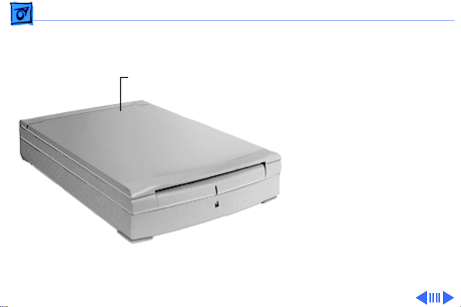
Overview
Color OneScanner 1200/30
The Color OneScanner
1200/30 is a compact,
digital-image color scanner
with a maximum
mechanical resolution of
600 x 1200 dpi.
Basics Overview - 2
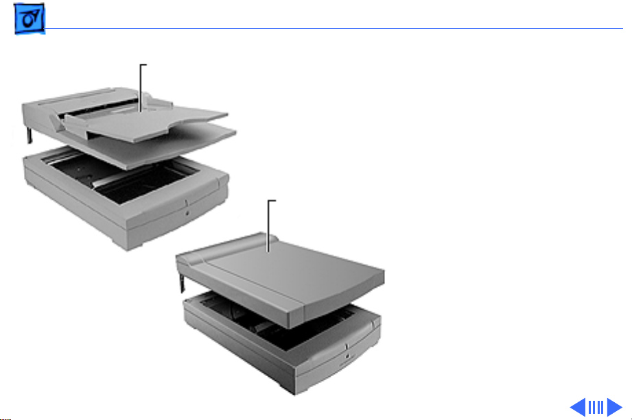
Automatic Document Feeder
Transparent Media
Adapter
Optional accessories include
• Automatic Document
Feeder (ADF) with a 20sheet capacity paper tray
• Transparent Media
Adapter (TMA) that does
a true negative-topositive conversion of
film negatives or
overhead projector
transparencies

Basics Overview - 3
Scanner Features
Features of the Color OneScanner 1200/30 include the
following:
• 600 x 1200 dpi optical, 4800 x 4800 dpi interpolated,
resolution for improved Optical Character Recognition
(OCR) accuracy
• 30-bit scanning depth color that recognizes more than
one billion colors
• Support for PICT, TIFF, GIF, JPEG, EPS, BMP, and
Photoshop; compatible with most popular word
processing, presentation, image-editing, page layout,
and web-authoring software for the Macintosh
• OneScanner Dispatcher software that integrates with
popular applications and provides the tools to scan, edit,
and archive images or documents; supports Drag and
Drop, and controls OCR, OCR to HTML conversion,
printing, faxing, copying, and retrieving images

Basics Overview - 4
• Small desktop footprint of 16.3 in by 11.3 in
• Updated version of ColorSync for the closest possible
color match between what is scanned, seen on the
monitor, or printed
• Updated version of Xerox TextBridge for converting
scanned documents into editable text or HTML format for
a Web page
• Low-temperature lamp that provides better image
quality and protects valuable originals from heat damage
• Optional 20-sheet capacity Automatic Document Feeder
(ADF)
• Optional Transparent Media Adapter (TMA) that
supports scanning transparent film sizes from 35 mm to
8.5 x 11 inches, and provides a highly accurate
negative-to-positive film conversion
Basics Overview - 5
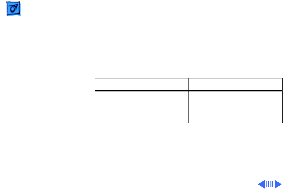
Product Comparison
The Color OneScanner 1200/30 and the Color OneScanner
600/27 share many features. However, the Color
OneScanner 1200/30 provides superior resolution and
color recognition as shown in the following table:
Color OneScanner 1200/30 Color OneScanner 600/27
30 bits, 600 x 1200 pixels 27 bits, 300 x 600 pixels
Recognizes more than onebillion colors
The Apple Color OneScanner 1200/30 also includes
enhanced software versions of OneScanner Dispatcher and
Xerox TextBridge. In addition, the Color OneScanner 1200/
30 includes bundled software—Kai’s Power Tools and
Convolver—for advanced image manipulation.
Recognizes up to 134million colors

Basics Overview - 6
Scanner Operation
Clicking the icon at left launches a MoviePlayer animation
sequence that shows the three scanning cycles:
• Flatbed scanning where the document remains stationary
and the scanner lamp moves to scan from the front
• Automatic Document Feeder (ADF) scanning where the
document moves and the scanner lamp remains in one
position to scan from the front
• Transparent Media Adapter (TMA) scanning where the
document remains stationary and the TMA lamp moves to
scan from the back

Basics Overview - 7
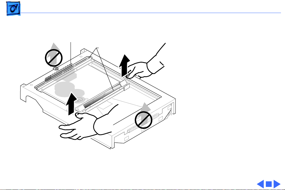
Optical Assembly Handling Precautions
Issue
: The Color One Scanner 1200/30 optical assembly is
being damaged during removal.
Solution:
by the longer sides (see illustration on next page) so that the
printed circuit board (CCD unit) on the underside will not
be damaged. The CCD unit is a delicate part located on the
front, or shorter side of the assembly. If a service provider
grabs or touches the CCD unit while removing or replacing
the scanner, the scanner may not function. In addition, new
packing was designed for the scanner unit.
Note
Assembly in Take Apart.
Apple recommends handling the scanner assembly
: For additional information, refer to the Optical
Basics Overview - 8
Hold or lift the optical
assembly by the longer
CCD Unit
Mirrors
sides, never by the shorter
sides.
Caution:
Do not touch the
printed circuit board (CCD
Unit) or the mirrors.

K
Service Source
Specifications
Apple Color OneScanner 1200/30

Specifications Characteristics (Flatbed) - 1
Characteristics (Flatbed)
Scanner T ype
Scanner Resolution
Maximum Document Size
Speed
Flatbed, single-pass, 30-bit scanning
600 x 1200 dpi
4800 x 4800 dpi interpolated
8.5 x 11.7 in. (21.6 x 29.2 cm)
8.5 x 14 in. (21.6 x 35.6 cm) with optional Automatic Document
Feeder (ADF)
6 seconds (full-page preview)
20 seconds (US letter size)
Monochrome: 10 seconds (US letter size)

Specifications Characteristics (Flatbed) - 2
Interface
Options
System Requirements
SCSI-2
Automatic Document Feeder (ADF)
Transparent Media Adapter (TMA)
13-inch display or larger
System software version 7.5 or later
At least 8 MB of RAM (need to increase memory additional 2 MB
when using OneScanner Dispatcher with Kai’s Power Tools or
Convolver; 12 MB required to use OneScanner Dispatcher and
Xerox TextBridge OCR software simultaneously)

Specifications Electrical - 3
Electrical
Line V oltage
Frequency
Power Consumption
100/120/200/220/240 VAC ± 10%
50–60 Hz
35 W maximum

Specifications Physical - 4
Physical
Size
Weight
Height: 3.1 in (79 mm)
Width: 11.3 in (287 mm)
Depth: 16.3 in (414 mm)
12.1 lb (5.5 kg)

Specifications Environmental - 5
Environmental
Operating Temperature
Relative Humidity
With the ADF: 50 to 90.5°F (10 to 32.5°C)
Without the ADF: 41 to 95°F (5 to 35°C)
With the ADF: 20 to 80% noncondensing
Without the ADF: 15 to 85% noncondensing

K
Service Source
Troubleshooting
Apple Color OneScanner 1200/30

Troubleshooting General/ - 1
General
The Symptom Charts included in this chapter will help you
diagnose specific symptoms related to your product. Because cures
are listed on the charts in the order of most likely solution, try
the first cure first. Verify whether or not the product continues to
exhibit the symptom. If the symptom persists, try the next cure.
(Note: If you have replaced a module, reinstall the original module
before you proceed to the next cure.)
If you are not sure what the problem is, or if the Symptom Charts
do not resolve the problem, refer to the Flowchart for the product
family.
For additional assistance, contact Apple Technical Support.
Troubleshooting Wiring Diagram/ - 2
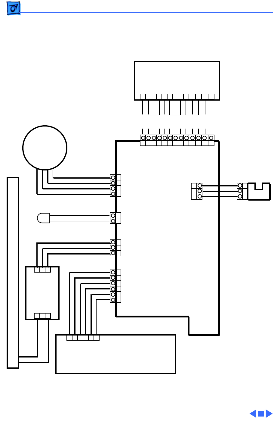
Wiring Diagram
CDD Drive Board
(Optical Assembly)
J201
1 2 3 4 5 6 7 8 9 10 11 12 13
YEL
YEL
YEL
YEL
YEL
YEL
YEL
YEL
YEL
YEL
YEL
YEL
Drive Motor
LED
1 2 3
J401
Inverter
Scanning Lamp (Optical Assembly)
Board
J402
1 2 3
BRN
ORN
RED
YEL
RED
BLK
RED
BLU
WHT
BRN
BLK
ORN
BLK
BLK
BLU
J301
J311
A
1
2
A*
3
B
4
B*
J309
12+5V
GND
J310
1
+24V
2
GND
3
LON*
J307
1
+5V
2
DGND
3
+12V
4
AGND
5
24V GND
6
+24V
1 2 3 4 5 6 7 8 9 10 11 12 13
BGR
GND
+12V
+A5V
CPCKN
RSN
SPCKN
SHN
F2N
F1N
J306
1
HPSNS
2
GND
3
VCC
Logic Board
BRN
YEL
BLU
Home
Position
Sensor
1
2
3
WHT
WHT
1 2 3 4 5 6
J101
Power Supply Board

Troubleshooting Symptom Charts/Normal Start-Up Sequence (Flatbed Scanning)
Symptom Charts
Normal Start-Up Sequence (Flatbed Scanning)
Important:
the start-up sequence. Even when turned off, some computers will
not allow the scanner’s normal start-up sequence to begin if the
SCSI cable is connected.
1 Power on
2 Power LED lights
3 Logic board self-tests
4 Lamp turns on
5 Optical assembly moves to home position sensor at top of
6 Lamp turns off, then on
7 Lamp intensity checked with reflection of white on back of
8 Origin of scan is determined by black strip on back of glass
9 Lamp moves about 3 mm down
10 Lamp moves back to home position sensor
11 Lamp turns off
12 Ready
Disconnect the scanner’s SCSI cable before beginning
glass
glass
Start-Up Troubleshooting Tips
When scanner is
turned on, there is a
chattering sound and
it will not scan
When trying to scan
from the Dispatch
software, this
message appears:
“Unable to initialize
the scanner driver.
Either the scanner is
not turned on,
connected, or already
in use by another
application.”
The SCSI select switch
doesn’t select the
correct SCSI ID
Unlock the scanner by opening the top cover and using a coin or
flat-blade screwdriver to turn the locking mechanism, located at
the top of the glass.
unlock icon is at 90 degrees from the slot. See the Additional
Procedures chapter for more information.
1 The most common cause is that the scanner was turned on
after the Macintosh. Always be sure the scanner is turned on,
then turn on the Macintosh. Observe the INITs as the
Macintosh starts up. The INIT for the scanner appears as a
side view of the scanner. This is the driver loading.
2 If the scanner INIT does not appear, reinstall the scanner
driver. If the icon appears with an “X” through it, there is a
SCSI problem.
3 Check the SCSI ID and cables.
The label may not be lined up correctly to the position of the
switch. Put the switch in the 12 o’clock position and then count to
the correct SCSI ID.
Note:
The arrow that points to the lock or

Troubleshooting Symptom Charts/General Troubleshooting - 4
General Troubleshooting
No LED (no power) 1 Check external power cord and incoming voltage.
2 Remove the covers, glass, and optical assembly. Check AC
voltage to power supply board by turning on power and
testing for rated AC voltage at the AC input pin (pin L) on the
power supply board. If readings are not to rated voltages,
replace power supply board.
3 With power off, reconnect the optical assembly at J301.
Turn on power and check voltages at J101.
J101 DC Voltage
GND-1 4.75 to 5.25
GND-3 11.4 to 12.6
GND-6 21.6 to 26.4
4 If any voltages are not correct, replace the power supply
board.
5 Turn off scanner. With power off, remove connector J301
from the logic board. Turn on power and recheck the voltages
at J101. If readings are within specified ranges, replace the
optical assembly since the CCD driver is faulty.
6 Turn off scanner and reconnect J301.
7 With power off, remove connector J311 from the logic
board. Turn on power and recheck the voltages at J101. If
readings are within specified ranges, replace the drive
motor.
8 Turn off scanner and reconnect J311.
9 With power off, remove connector J306 from the logic board.
10 Turn on power and recheck voltages at J101. If readings are
within specified ranges, replace the home position sensor
and/or home position sensor cable.
11 Turn off scanner and reconnect J306.
12 With power off, remove connector J309 from the logic board.
13 Turn on power and recheck voltages at J101. If readings are
within specified ranges, replace the LED cable. If readings
are not within specified ranges, replace the logic board.
14 Turn off scanner and reconnect J309.
Troubleshooting Symptom Charts/General Troubleshooting - 5
Lamp does not light 1 Check connection at J402.
2 Remove the covers, glass, and optical assembly. With power
off, reconnect the optical assembly at J301. Turn on power
and check voltages at J101.
J101 DC Voltage
GND-1 4.75 to 5.25
GND-3 11.4 to 12.6
GND-6 21.6 to 26.4
3 If any voltages are not correct, replace power supply board.
4 Connect J310 pin 2 to ground. Verify that scanner lamp
lights. If lamp does not light, replace logic board.
5 Connect J402 pin 2 on the inverter board to ground. Verify
that scanner lamp lights. If lamp does not light, replace the
inverter board. If lamp lights, replace the optical assembly.
Lamp turns on, but
scanner drive motor
is not working
1 Make sure scanner optical assembly is unlocked. See
Additional Procedures chapter for information.
2 Check connections at J307 and J311.
3 Remove optical assembly and turn on scanner. If motor
works, make sure glass is oriented correctly. Go to symptom
“Scanner does not find Home sensor” in this chapter.
4 With the scanner on, check voltages at connector J101.
J101 DC Voltage
GND-1 4.75 to 5.25
GND-3 11.4 to 12.6
GND-6 21.6 to 26.4
5 If any voltages are not correct, go to symptom “No LED (no
power)” in this chapter.
6 Turn off power and check resistance in the drive motor by
measuring at connector J311.
J311 pins Resistance
1 and 2 About 17.3 ohms
3 and 4 About 17.3 ohms
7 If resistance is not correct, replace drive motor. If
resistance is correct, check connection at J311 and if it is
normal, replace logic board.

Troubleshooting Symptom Charts/General Troubleshooting - 6
Problem with lamp
intensity checked or
origin of scan area
Scanner does not find
Home sensor;
scanner drive motor
does not move
mirror, even when
optical assembly is
removed
When the Apple Color
OneScanner Plug-in
is moved to the
Photoshop Acquire
folder, it doesn’t
work. The Dispatch
doesn’t work either.
1 Make sure glass is oriented correctly and that nothing is
blocking the black strip or upper portion of the glass.
2 Replace glass.
1 Inspect mirror assembly on optical assembly for damage to
the home position flag. Replace optical assembly if needed.
2 Replace home sensor (photo-interrupter).
3 Replace logic board.
The Apple Color OneScanner Plug-in must be left in its folder. You
can make a copy of it, or an alias, and put that in the Acquire
folder. You cannot change the name of the original plug-in. It must
keep the name “Apple Color OneScanner.”
Troubleshooting Symptom Charts/Image Defects - 7
Image Defects
Image not correct,
white only, black
only, or gray.
1 Check SCSI cable connection.
2 Check whether scanning lamp is lighting. If not, go to
symptom “Lamp does not light” in this chapter.
3 With power off, remove connector J307. Turn on power and
check voltages at J101 on the power supply board.
J101 DC Voltage
GND-1 4.75 to 5.25
GND-3 11.4 to 12.6
GND-6 20.4 to 27.6
4 If these voltages are not present, go to symptom “No LED (no
power)” in this chapter.
5 Replace logic board.
6 Check connector at J301 and if it is normal, replace optical
assembly.

Troubleshooting Symptom Charts/Image Defects - 8
Image blurred 1 Use a soft, dry cloth to clean top of glass.
2 Check mirror for dust or obstructions.
3 Replace optical assembly.
A
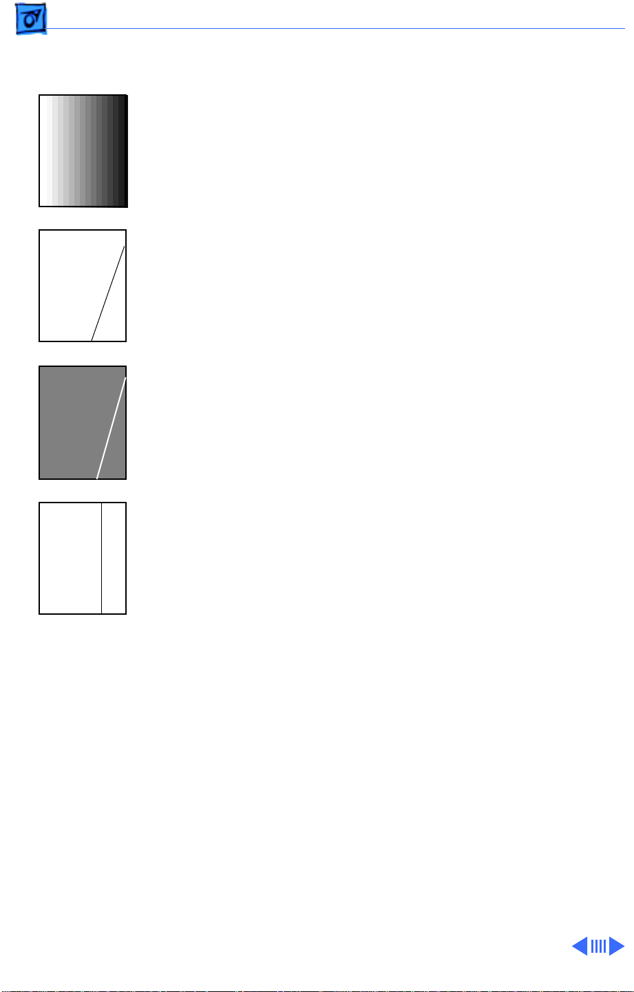
Troubleshooting Symptom Charts/Image Defects - 9
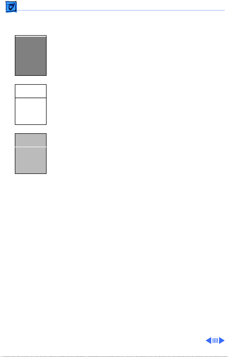
Uneven image density
or lines (horizontal)
A
A
1 Use a soft, dry cloth to clean top of glass.
2 Check underside of glass to make sure the white plate is
intact.
3 Check connections at J301 and J310 on the logic board.
4 Replace logic board.
5 Replace optical assembly.
A
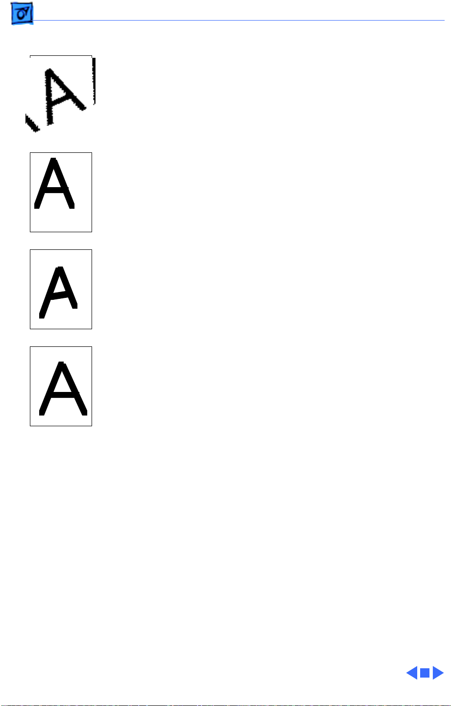
Troubleshooting Symptom Charts/Image Defects - 10
Uneven image density
or lines (vertical)
A
A
A
1 Use a soft, dry cloth to clean top of glass.
2 Check underside of glass to make sure the white plate is
intact.
3 Check mirrors for dust or obstructions.
4 Replace logic board.
5 Replace optical assembly.
A

Troubleshooting Symptom Charts/Image Defects - 11
Image is misaligned
(vertical)
1 Make sure the mirror on the optical assembly is not
obstructed.
2 Replace optical assembly.
Troubleshooting Symptom Charts/Image Defects - 12
Image is distorted 1 Replace optical assembly.
2 Replace logic board.

Troubleshooting Symptom Charts/Automatic Document Feeder (ADF) - 13
Automatic Document Feeder (ADF)
When using the
Automatic Document
Feeder (ADF), the
scan shows a blank
page or a strange
vertical pattern
Cannot fax multiple
pages with the ADF
ADF does not feed
paper to scanner
Check to see if paper has been left on the flatbed. Before using the
ADF, always check to see that the flatbed is empty.
Scan each page and merge them together before faxing them.
1 Check connection at document feeder connector cable.
2 Close document feeder cover completely.
3 Verify that document originals in the feeder are standard
office papers and do not exceed the maximum thickness of 2
mm (5/64 in) or 20 sheets.
4 Verify that document originals are free from
• Tears, perforations, or punch holes
• Curls or wrinkles
• Carbon backing or coarse texture
• Labels, tape, or glue
• Staples or clips
5 Replace logic board.

Troubleshooting Symptom Charts/Transparent Media Adapter (TMA) - 14
Transparent Media Adapter (TMA)
Lamp does not light;
lamp does not move
When scanner is
turned on, there is a
chattering sound and
it will not scan
Scanned image is
overexposed
Scanned image is
reversed left-toright
Color quality is poor If using a film guide, align the “V” mark on the film guide with
1 Connect Transparent Media Adapter (TMA) connector cable.
2 Go to symptom “Lamp does not light” in this chapter.
Unlock the TMA lamp by tilting the TMA up and pressing the lock
switch located between the two hinges.
1 Verify that originals are loaded into the film guide correctly
so that there are no horizontal gaps around the perimeter of
the film and that any empty slots in the film guide are filled
by shutter strips.
2 Close the TMA cover securely.
Position the original so the desired image is face down.
the “V” mark on the scanner glass. If not using a film guide, place
the film or transparency on the scanner glass so the top edge of the
original is at least 15 mm away from the top edge of the scanner
glass. Do not obstruct the calibration strip.
A mark or line
consistently appears
in same place on
scanned images
Edge of the scanned
image is dark
Striped pattern
appears on scanned
image
1 Use a soft, dry cloth to clean diffuser.
2 Wipe film or transparency with a clean, dry cloth.
3 Replace film or transparency with unmarked copy.
1 Reposition the film or transparency so it is 7 mm from the
edge of the scanner glass.
2 Verify that the TMA cover is closed securely.
Use a soft, dry cloth to clean diffuser, film, or scanner glass.

K
Service Source
T ak e Apart
Apple Color OneScanner 1200/30

Take Apart Top Cover with Hinge - 1
Top Cover with Hinge
Top Cover with Hinge
No preliminary steps are
required before you begin
this procedure.

Take Apart Top Cover with Hinge - 2
Lift the top cover straight
off the scanner.
Top Cover with Hinge

Take Apart Glass Cover - 3
Glass Cover
Before you begin, remove
Glass Cover
the top cover with hinge.
Caution:
precautions in Bulletins/
Safety.
Review the ESD

Take Apart Glass Cover - 4
1 Using a jeweler’s flat-
blade screwdriver,
release the two glass
cover latches.
2 While pressing the
power switch, carefully
lift off the glass cover.
Power Switch
Latch
Caution:
When
removing the glass cover
assembly, be sure you
don’t damage the LED
cable.

Take Apart Glass Cover - 5
3 Raise the glass cover
assembly to 90 degrees
LED Cable
and disconnect the LED
cable by pushing the LED
toward the top of the
glass cover.
4 Remove the glass cover
from the scanner.
Glass Cover
Caution:
When the glass
cover is removed, do not
tilt the scanner on its
side, or the glass may
slip off.

Take Apart Glass Cover - 6
5 Grasp the glass by its
edges, and taking care
not to bend the glass
holder clips, slightly lift
the glass and rotate it
clockwise to release it
from the glass holder
clips.
Handle the glass by its
edges and place it in a
clean area.
Glass Holder
Clip
Glass Holder
Clip
Glass

Take Apart Optical Assembly - 7
Optical Assembly
Optical Assembly
Before you begin, remove
the following:
• Top cover with hinge
• Glass cover assembly
Caution:
precautions in Bulletins/
Safety.
1 Verify that
Review the ESD
• Scanner power is off
• Power cord is
connected
• SCSI cable is
disconnected

Take Apart Optical Assembly - 8
2 Set the SCSI ID switch to
7 (terminator off
position).
3 Turn on the scanner
power.
Wait for the startup
sequence to finish and
the lamp to turn off.
(For a description of the
normal startup
sequence, refer to the
Troubleshooting
chapter.)
SCSI ID Switch
4 Set the SCSI ID switch to
0 (terminator on
position).

Take Apart Optical Assembly - 9
Screw
Screw
Mirror
Screw
Screw
Screw
Screw
5 Set the SCSI ID switch
back to 7, then back to 0,
and finally back to 7.
6 After about 10 seconds,
the lamp and mirror
will move. When the
mirror has reached the
position where it is
between the set of four
screws on the bottom,
turn off the scanner.
7 Using a Phillips
screwdriver, remove
• Four screws and
lockwashers
• Two screws at rear
feet

Take Apart Optical Assembly - 10
8 Using a needlenose
pliers, carefully remove
connector J402 from the
logic board.
J402

Take Apart Optical Assembly - 11
9 Carefully lift the optical
Longer Side
assembly and remove
connector J301 from the
inverter board.
J301
CCD Unit
Caution:
scanner assembly by the
Handle the
longer sides so that the
printed circuit board
(CCD unit) on the
underside will not be
damaged.

Take Apart Optical Assembly - 12
10
Note:
Do not touch the
mirror or the printed
circuit board (CCD unit)
Mirror
Optical
Assembly
on the optical assembly.
Remove the optical
assembly from the
scanner.
CCD Unit

Take Apart LED Cable - 13
LED Cable
LED Cable
Before you begin, remove
the following:
• Top cover
• Glass cover assembly
• Optical assembly
Caution
precautions in Bulletins/
Safety.
: Review the ESD

Take Apart LED Cable - 14
1 Disconnect connector
Tie Wrap
Cable Clip
J309
J309 from the logic
board.
2 Remove the cable from
the cable clip and cut the
tie wrap.

Take Apart LED Cable - 15
3 Remove the tape and LED
cable from the bottom
LED Cable
Tape
case.

Take Apart Inverter Board - 16
Inverter Board
Inverter Board
Before you begin, remove
the following:
• Top cover
• Glass cover assembly
• Optical assembly
Caution
precautions in Bulletins/
Safety.
: Review the ESD

Take Apart Inverter Board - 17
1 Disconnect connector
J402
J402 from the inverter
board.

Take Apart Inverter Board - 18
2 Using a pair of
needlenose pliers,
squeeze the card spacer
tabs and remove the
inverter board.
Card Spacer

Take Apart Drive Motor and Bracket - 19
Drive Motor and Bracket
Before you begin, remove
the following:
• Top cover
• Glass cover assembly
• Optical assembly
Drive Motor
Caution:
precautions in Bulletins/
Safety.
Review the ESD

Take Apart Drive Motor and Bracket - 20
1 Remove connector J311
from the logic board.
2 Remove the cable from
the cable clip.
J311 Cable Clip

Take Apart Drive Motor and Bracket - 21
3 Remove the two screws
and washers.
4 Remove the drive motor
and bracket from the
bottom case.
Screw
Drive Motor
Screw

Take Apart Drive Motor and Bracket - 22
5 If necessary, lift off and
remove the gear from
the motor.
Spindle
Replacement Note:
Be
sure that the gear is
lined up with the flat
side of the drive motor
spindle when
reinstalling.
Drive Motor Gear

Take Apart Drive Motor and Bracket - 23
6 Carefully remove the
drive motor damper.
Drive Motor Bracket
7 Using a Phillips
screwdriver, remove
the two screws from the
drive motor bracket.
8 Remove the drive motor
from the bracket.
Drive Motor
Drive Motor
Damper

Take Apart Power Supply Board - 24
Power Supply
Power Supply Board
Board
Before you begin, remove
the following:
• Top cover
• Glass cover assembly
• Optical assembly
• Inverter board
Caution:
precautions in Bulletins/
Safety.
Note:
board before returning the
power supply to Apple.
Review the ESD
Remove the inverter

Take Apart Power Supply Board - 25
1 Cut the tie wraps and
remove connector J307
from the logic board.
2 Remove the cables from
the cable clip.
J307Logic Board
Cable Clip

Take Apart Power Supply Board - 26
3 Slide the power switch
up and out of the bottom
case.
4 Remove the two screws
that hold the power
receptacle.
Screw
Power Switch
Screw
Power Receptacle

Take Apart Power Supply Board - 27
5 Remove the two
Screw
mounting screws.
6 Remove the ground
screw and lockwasher.
Power Supply
Board
7 Remove the power
supply board from the
scanner.
Ground Screw
Screw

Take Apart Logic Board - 28
Logic Board
Before you begin, remove
the following:
Logic Board
• Top cover
• Glass cover assembly
• Optical assembly
• Drive motor
Caution:
precautions in Bulletins/
Safety.
Review the ESD

Take Apart Logic Board - 29
1 Locate the cables at
J306 and J310 on the
logic board.
• If the cables are
soldered, disconnect
the other end of the
cables at the home
position sensor and at
the inverter board.
• If the cables have
connectors at J306
and J310, disconnect
them from the logic
board.

Take Apart Logic Board - 30
2 Disconnect the following
cables from the logic
board:
• J307
• J309

Take Apart Logic Board - 31
3 Using a Phillips
screwdriver, remove
the two mounting
screws from the SCSI
connector.
4 Using a hex driver,
remove the two mounting
screws from the
interface connector.
SCSI ConnectorInterface Connector

Take Apart Logic Board - 32
5 Remove the corner
screw from the logic
Logic Board
Screw
board.

Take Apart Logic Board - 33
6 Using needlenose pliers,
squeeze together the card
Card Spacer
Logic Board
spacers and lift off the
logic board.

Take Apart Logic Board - 34
7 Remove the shield plate
Logic Board
Shield Plate
from the logic board.

Take Apart Home Position Sensor (Photo-Interrupter) and Cable - 35
Home Position
Home Position Sensor
(Photo-Interrupter)
Cable
Sensor (PhotoInterrupter) and
Cable
Before you begin, remove
the following:
• Top cover
• Glass cover assembly
• Optical assembly
Caution:
precautions in Bulletins/
Safety.
Review the ESD

Take Apart Home Position Sensor (Photo-Interrupter) and Cable - 36
1 Remove the cable from
connector J306 on the
Home Position Sensor
Cable
logic board and the
connector on the home
position sensor (photointerrupter).
Logic Board

Take Apart Home Position Sensor (Photo-Interrupter) and Cable - 37
2 Press in the two latches
and lift up to remove the
home position sensor
from the bottom case.
Home Position
Sensor

Take Apart Feet - 38
Feet
Before you begin, remove
Rear Foot
Rear Foot
the following:
• Top cover
• Glass cover assembly
• Optical assembly
Front Foot
Front Foot
Caution:
precautions in Bulletins/
Safety.
Review the ESD

Take Apart Feet - 39
1 Slide the rear foot off of
the bottom case. Repeat
for other rear foot.
Rear Foot

Take Apart Feet - 40
2 Press down and unlatch
the front foot from the
bottom case. Repeat for
Bottom Case
Front Foot
other front foot.

Take Apart Automatic Document Feeder - 41
Automatic
Automatic Document Feeder
Document Feeder
No preliminary steps are
required before you begin
this procedure.
Caution:
precautions in Bulletins/
Safety.
Review the ESD

Take Apart Automatic Document Feeder - 42
1 Lift the document feeder
straight off the scanner.
Document Feeder

Take Apart Automatic Document Feeder - 43
Paper Separator
1 Lift up the top cover of
Document Feeder Top Cover
the document feeder.

Take Apart Automatic Document Feeder - 44
2 Do not pull on the
rubber piece on the
paper separator. It is
held in place by a metal
clip and will come off if
pulled.
Push down and press
forward on the paper
separator.
3 Remove the paper
separator.
Rubber Piece
Paper Separator

Take Apart Automatic Document Feeder - 45
Delivery Guide
and Deflector
Document Feeder
Delivery Guide and
Deflector
1 Turn the document
feeder over.

Take Apart Automatic Document Feeder - 46
2 Press in the two latches
and swing out the
Delivery Guide
Latch
and Deflector
Latch
delivery guide and
deflector.

Take Apart Automatic Document Feeder - 47
3 Remove the delivery
guide and deflector.
Delivery Guide
and Deflector

Take Apart Automatic Document Feeder - 48
4 Remove the delivery
guide from the deflector.
Delivery Guide
Deflector

Take Apart Automatic Document Feeder - 49
Replacement Note:
Tab
Before installing the
deflector back into the
document feeder, make
Tab
sure the two holes on the
delivery guide line up
with the two tabs on the
deflector.

Take Apart Automatic Document Feeder - 50
Replacement Note: Slip
the delivery guide back
under the plastic sheet
Plastic Sheet
Delivery Guide
on the document feeder
and snap the deflector in
place.

Take Apart Transparent Media Adapter - 51
Transparent
Transparent Media Adapter
Media Adapter
No preliminary steps are
required before you begin
this procedure.
Caution: Review the ESD
precautions in Bulletins/
Safety.

Take Apart Transparent Media Adapter - 52
1 Lift the Transparent
Media Adapter straight
Transparent Media
Adapter
off the scanner.

Take Apart Transparent Media Adapter - 53
Diffuser
1 Place the Transparent
Media Adapter so the
Screwdriver
Diffuser
Tab
hinges face up.
2 Using a jeweler’s flat-
blade screwdriver,
unlatch the diffuser
from its ten tabs.

Take Apart Transparent Media Adapter - 54
3 Tilt the diffuser up to
release it from the
Diffuser
Transparent Media
Adapter unit.

K
Service Source
Additional Procedures
Apple Color OneScanner 1200/30

Additional Procedures Unlocking the Scanner - 1
Unlocking the Scanner
Before you begin, remove
the top cover with hinge.
Lock

Additional Procedures Unlocking the Scanner - 2
Using a coin or a flat-blade
Lock
screwdriver, rotate the
lock to the unlocked position.
Unlocked
Position

Additional Procedures Changing the SCSI ID - 3
Changing the SCSI ID
No preliminary steps are
required before you begin
this procedure.
SCSI Switch
Caution:
precautions in Bulletins/
Safety.
Review the ESD

Additional Procedures Changing the SCSI ID - 4
There are two sets of SCSI ID
numbers. Choose the set
that matches your SCSI
termination configuration:
• The numbers on the left
are with SCSI
termination turned off.
Use these numbers if an
external SCSI terminator
is installed.
• The numbers on the right
are with SCSI
termination turned on.
Use these numbers if no
external SCSI terminator
SCSI Termination
Off
SCSI Termination
On
is installed.

Additional Procedures Changing the SCSI ID - 5
Turn the switch to the
desired number.
SCSI ID Switch

Additional Procedures Moving the Optical Assembly to Service Position - 6
Moving the
Optical Assembly
Optical Assembly
to Service Position
Before you begin, remove
the top cover with hinge.
1 Make sure
• Scanner power is off
• Power cord is
connected
• SCSI cable is
disconnected

Additional Procedures Moving the Optical Assembly to Service Position - 7
2 Set the SCSI ID switch to
7 (terminator off
position).
3 Turn on the scanner
power.
Wait for the start-up
sequence to finish and
the lamp to turn off.
(For a description of the
normal start-up
sequence, refer to the
Troubleshooting
chapter.)
SCSI ID Switch
4 Set the SCSI ID switch to
0 (terminator on
position).

Additional Procedures Moving the Optical Assembly to Service Position - 8
5 Set the SCSI ID switch
Mirror
Optical Assembly
back to 7, then back to 0,
and finally back to 7.
6 The optical unit will now
move. When the mirror
has reached the position
where it is between the
set of four screws on the
bottom, turn off the
scanner.

K
Service Source
Exploded V ie w
Apple Color OneScanner 1200/30

Exploded View 1
Cover,
Delivery
Guide Sheet
922-2048
Top w/Hinge
922-1930
Deflector
Paper
Separator
922-2047
Power Supply Board
922-2049
Document Feeder
Whole Unit
661-1119
Optical Assembly
661-1089
Cable Sensor
922-1937
661-1085
Photo-Interrupter
922-1353
Plate, Shield
922-1934
Logic Board
661-1088
Gear, Motor
922-2042
Bracket, Motor
922-2046
Pad, Damper,
Motor
922-2045
Cover Glass
922-1931
Glass w/ Scale
922-2024
Holder, Glass
922-1933
Kit,
Foot
076-0535
Inverter
Board
922-1936
Cable, LED
922-1935
Motor, Drive
922-2296
 Loading...