


SPX-Z18T


Points to Observe for Safe Usage
• Read this manual carefully before starting operation and
use this system safely. We cannot be responsible for
problems resulting from failure to observe the instructions
in this manual.
• This manual uses various pictorial displays to show how to
use this product safely and to avoid harm to yourself and
others and damage to your property. Here is what these
pictorial displays mean. Understanding them is important
for reading this manual.
• Meaning of displays
This label is intended to alert the user to the
Warning
Caution
presence of important operating instructions.
Failure to heed the instructions will result in
severe injury or death.
This label is intended to alert the user to the
presence of important operating instructions.
Failure to heed the instructions can result in
injury or material damage.
Warning
DO NOT DISASSEMBLE OR ALTER. Doing so may result in an
accident, fire or electric shock.
KEEP SMALL OBJECTS SUCH AS BATTERY OUT OF THE REACH OF
CHILDREN. Swallowing them may result in serious injury. If
swallowed, consult a physician immediately.
DO NOT INSTALL IN LOCATIONS WHICH MIGHT HINDER VEHICLE
OPERATION, SUCH AS THE STEERING WHEEL OR GEARSHIFT. Doing
so may obstruct forward vision or hamper movement etc. and
results in serious accident.
DO NOT DAMAGE PIPE OR WIRING WHEN DRILLING HOLES. When
drilling holes in the chassis for installation, take precautions so
as not to contact, damage or obstruct pipes, fuel lines, tanks or
electrical wiring. Failure to take such precautions may result in
fire.
DO NOT USE BOLTS OR NUTS IN THE BRAKE OR STEERING SYSTEMS
TO MAKE GROUND CONNECTIONS. Bolts or nuts used for the brake
or steering systems (or any other safety-related system), or tanks
should NEVER be used for installations or ground connections.
Using such parts could disable control of the vehicle and cause
fire etc.
DO NOT INSTALL THE MONITOR NEAR THE PASSENGER SEAT AIR
BAG. If the unit is not installed correctly the air bag may not
function correctly and when triggered the air bag may cause the
monitor to spring upwards causing an accident and injuries.
MAKE THE CORRECT CONNECTIONS. Failure to make the proper
connections may result in fire or product damage.
Caution
USE SPECIFIED ACCESSORY PARTS AND INSTALL THEM SECURELY.
Be sure to use only the specified accessory parts. Use of other
than designated parts may damage this unit internally or may
not securely install the unit in place. This may cause parts to
become loose resulting in hazards or product failure.
DO NOT INSTALL IN LOCATIONS WITH HIGH MOISTURE OR DUST.
Avoid installing the unit in locations with high incidence of
moisture or dust. Moisture or dust that penetrates into this unit
may result in product failure.
HAVE THE WIRING AND INSTALLATION DONE BY EXPERTS. The wiring
and installation of this unit requires special technical skill and
experience. To ensure safety, always contact the dealer where you
purchased this product to have the work done.
ARRANGE THE WIRING SO IT IS NOT CRIMPED OR PINCHED BY A
SHARP METAL EDGE. Route the cables and wiring away from
moving parts (like the seat rails) or sharp or pointed edges. This
will prevent crimping and damage to the wiring. If wiring passes
through a hole in metal, use a rubber grommet to prevent the
wire’s insulation from being cut by the metal edge of the hole.
HALT USE IMMEDIATELY IF A PROBLEM APPEARS. Failure to do so
may cause personal injury or damage to the product. Return it
to your authorized Alpine dealer or the nearest Alpine Service
Center for repairing.
Points à respecter pour une utilisation sûre
•
Lire attentivement ce manuel avant de commencer l’opération
et l’utilisation du système en toute sécurité. Nous dégageons
toute responsabilité des problèmes résultant du non-respect
des instructions décrites dans ce manuel.
•
Ce manuel utilise divers affichages illustrés pour montrer comment utiliser
cet appareil en toute sécurité, pour éviter de s’exposer soi-même et les
autres personnes aux dangers et pour éviter d’endommager l’appareil.
Voici la signification de ces affichages illustrés. Il est important de bien les
comprendre pour la lecture de ce manuel.
• Signification des affichages
Cette étiquette a pour but de prévenir
Avertissement
Attention
l’utilisateur de la présence d’instructions
importantes. Si ces instructions ne sont pas
suivies, des blessures graves ou mortelles
risquent d’être occasionnées.
Cette étiquette a pour but de prévenir l’utilisateur
de la présence d’instructions importantes. Si
ces instructions ne sont pas suivies, des
blessures ou des dommages matériels risquent
d’être occasionnés.
English/Français
Avertissement
NE PAS DESASSEMBLER NI MODIFIER L’APPAREIL. Il y a risque
d’accident, d’incendie ou de choc électrique.
GARDER LES PETITS OBJETS COMME LES PILES HORS DE PORTEE DES
ENFANTS. L’ingestion de tels objets peut entraîner de graves blessures.
En cas d’ingestion, consulter immédiatement un médecin.
NE PAS INSTALLER A DES ENDROITS SUSCEPTIBLES D’ENTRAVER
LA CONDUITE DU VEHICULE, COMME LE VOLANT OU LE LEVIER DE
VITESSES. La vue vers l’avant pourrait être obstruée ou les
mouvements gênés, etc., et provoquer un accident grave.
NE PAS ENDOMMAGER DE CONDUITES NI DE CABLES LORS DU
FORAGE DES TROUS. Lors du forage de trous dans le châssis en
vue de l’installation, veiller à ne pas entrer en contact,
endommager ni obstruer de conduites, de tuyaux à carburant
ou de fils électriques. Le non-respect de cette précaution peut
entraîner un incendie.
NE PAS UTILISER DES ECROUS NI DES BOULONS DU CIRCUIT DE FREINAGE OU
DE DIRECTION POUR LES CONNEXIONS DE MASSE. Les boulons et les écrous
utilisés pour les circuits de freinage et de direction (ou de tout autre système
de sécurité) ou les réservoirs ne peuvent JAMAIS être utilisés pour
l’installation ou la liaison à la masse. L’utilisation de ces organes peut
désactiver le système de contrôle du véhicule et causer un incendie, etc.
NE PAS INSTALLER LE MONITEUR PRES DU COUSSIN D’AIR DU
PASSAGER. Si l’appareil n’est pas installé correctement, il risque
d’empêcher le fonctionnement du coussin d’air, et si le coussin
se déploie, l’appareil risque d’être projeté dans l’habitacle,
causant un accident et des blessures.
EFFECTUER CORRECTEMENT LES CONNEXIONS. Il y a risque de
blessures ou de dommages à l’appareil.
Attention
UTILISER LES ACCESSOIRES SPECIFIES ET LES INSTALLER CORRECTEMENT.
Utiliser uniquement les accessoires spécifiés. L’utilisation d’autres
composants que les composants spécifiés peut causer des dommages
internes à cet appareil ou son installation risque de ne pas être effectuée
correctement. Les pièces utilisées risquent de se desserrer et de provoquer
des dommages ou une défaillance de l’appareil.
NE PAS INSTALLER A DES ENDROITS TRES HUMIDES OU POUSSIEREUX. Eviter
d’installer l’appareil à des endroits soumis à une forte humidité ou à de la
poussière en excès. La pénétration d’humidité ou de poussière à l’intérieur
de cet appareil risque de provoquer une défaillance.
FAIRE INSTALLER LE CABLAGE ET L’APPAREIL PAR DES EXPERTS. Le câblage
et l’installation de cet appareil requiert des compétences techniques et
de l’expérience. Pour garantir la sécurité, faire procéder à l’installation
de cet appareil par le distributeur qui vous l’a vendu.
FAIRE CHEMINER LE CABLAGE DE MANIERE A NE PAS LE COINCER CONTRE
UNE ARETE METALLIQUE. Faire cheminer les câbles à l’écart des pièces
mobiles (comme les rails d’un siège) et des arêtes acérées ou pointues.
Cela évitera ainsi de coincer et d’endommager les câbles. Si un câble
passe dans un orifice métallique, utiliser un passe-cloison en
caoutchouc pour éviter que la gaine isolante du câble ne soit
endommagée par le rebord métallique de l’orifice.
INTERROMPRE TOUTE UTILISATION EN CAS DE PROBLEME. Le non-respect
de cette précaution peut entraîner des blessures ou endommager
l’appareil. Retourner l’appareil auprès du distributeur Alpine agréé ou
un centre de service après-vente Alpine en vue de la réparation.
1

Contents / Contenu
Installation / Installation
Parts List / Liste des pièces
Woofer Installation / Installation du Woofer
Midrange Installation / Installation du haut-parleur médial
Tweeter Installation / Installation du Tweeter
Network Installation / Installation du circuit
Network connections / Connexions du circuit
Crossover Network / Circuit répartiteur
Crossover Network Introduction / Introduction au circuit répartiteur ................
Jumper Group Function / Fonction de groupe cavalier...................................
System Type 1 / Type de système 1 ................................................................
System Description / Description du système .............................................
Network Jumper Setting / Réglage du cavalier du circuit ...........................
System Type 2 / Type de système 2 ................................................................
System Description / Description du système .............................................
Network Jumper Setting / Réglage du cavalier du circuit ...........................
System Type 3 / Type de système 3 ................................................................
System Description / Description du système .............................................
Network Jumper Setting / Réglage du cavalier du circuit ...........................
System Type 4 / Type de système 4 ................................................................
System Description / Description du système .............................................22/38
Network Jumper Setting / Réglage du cavalier du circuit ...........................
Others / Autres
External dimensions / Dimensions externes ........................................................
Specifications / Spécifications..............................................................................
...................................................................................
............................................................
....................................
.........................................................
............................................................
........................................................
3
4
5
6
7
8
9/25
10/26
13/29
13/29
14/30
16/32
16/32
17/33
19/35
19/35
20/36
22/38
23/39
40
42
2
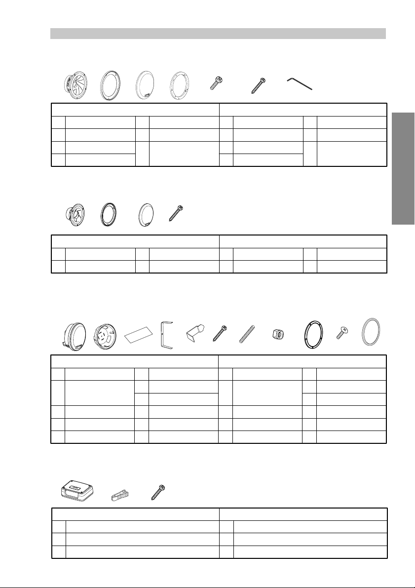
Parts List / Liste des pièces
Woofer / Woofer
1
2
X2 X2 X2 X2
3
4
English
Main Unit
1
Grille Ring
2
Grille
3
Adapter Ring
4
Screw M4 x 12
5
Screw ø4 x 19
6
Hexagonal
7
Wrench
Midrange / Haut-parleur médial
8
8
9
9
X2 X2 X2
Main Unit
Grille Ring
p
English
p
q
q
Grille
Screw ø4 x 19
Tweeter / Tweeter
w
w
e
r
t
y
er t io
X2 X2 X2 X2 X2 X2 X2
English
Main Unit
Mounting Cup
Terminal Cover
Spring
Mounting Clip
Screw ø4 x 19
u
Screw M4 x 25
i
M4 Nut
o
Mounting Ring
;
Screw ø4 x 12
a
Gasket
s
5
1
2
3
4
X6
8
9
yu
X10X8X4
w
e
montage
r
t Ressort
y
67
X10X10
Français
Unité principale
Bague de la grille
Grille
Bague d’accouplement
Français
Unité principale
Bague de la grille
;
Français
Unité principale
Coupelle de
Couvre-bornes
Collier de fixation
Vis M4 x 12
5
Vis ø4 x 19
6
Clé hexagonale
7
Grille
p
Vis ø4 x 19
q
a
X2
Vis ø4 x 19
u
Vis M4 x 25
i
Écrou M4
o
Bague de montage
;
Vis ø4 x 12
a
Garniture
s
English/Fran
çais
s
3-way network / Circuit répartiteur à 3 voies
d
Crossover network
d
Jumper Puller
f
Screw ø4 x 19
g
fg
X2X2
X6
English
d
f
g
Français
Circuit répartiteur
Mécanisme de tirage du cavalier
Vis ø4 x 19
3
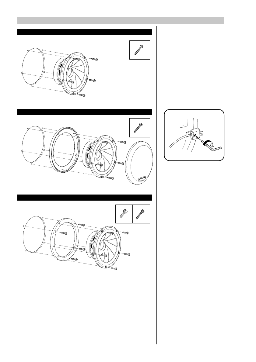
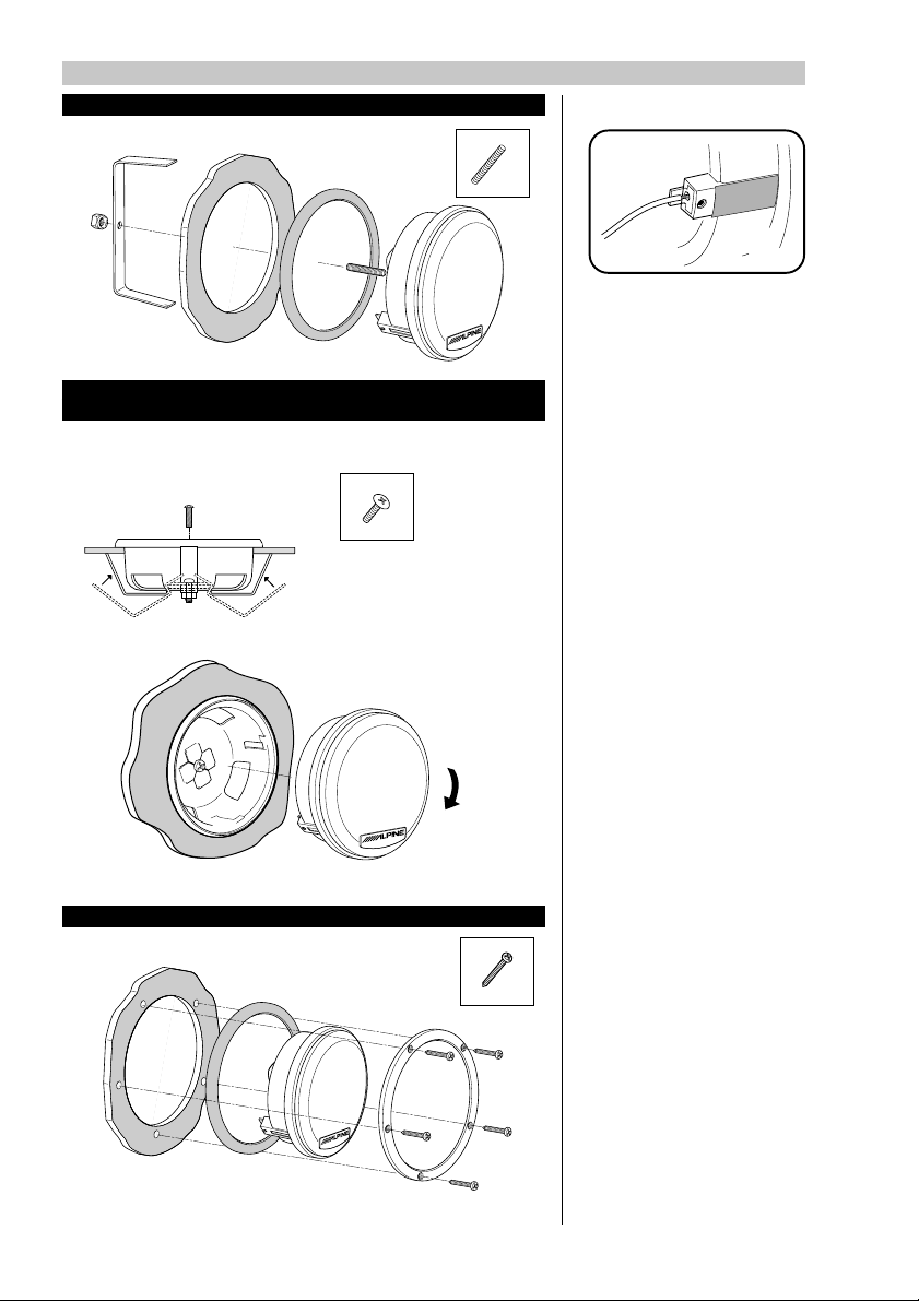
Woofer Installation / Installation du Woofer
Installation without a grille / Installation sans grille
6
Installation with a grille / Installation avec grille
6
Speaker Wire
Connections /
Raccordement des fils
d’enceinte
X5
X5
1. Insert the speaker wires
through the connection
holes. / Insérer les fils
d’enceinte dans les trous
de raccordement.
2. Fasten with a hexagonal
wrench. / Serrer avec
une clé hexagonale.
Installation with adapter rings / Installation avec bagues d’accouplement
5
X5
4
6
X4
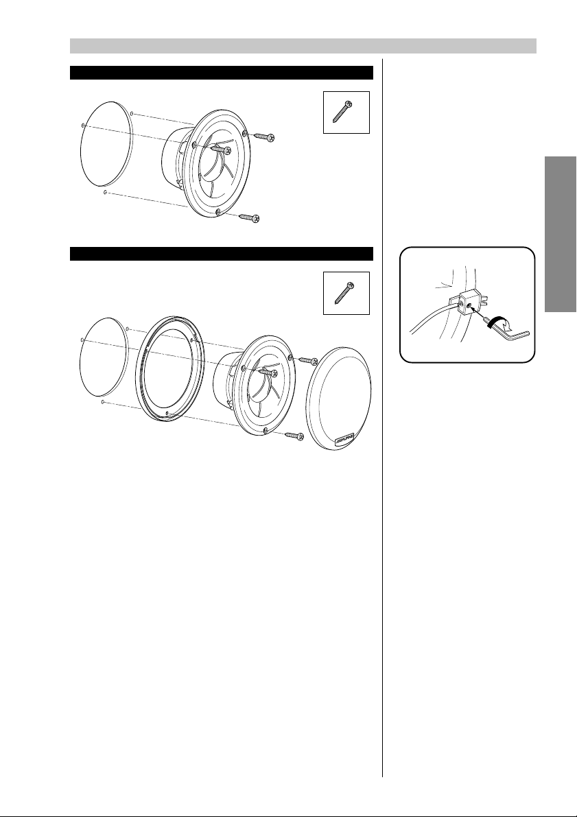
Midrange Installation / Installation du haut-parleur médial
Installation without a grille / Installation sans grille
q
X3
Speaker Wire
Connections /
Raccordement des fils
d’enceinte
1. Insert the speaker wires
2. Fasten with a hexagonal
through the connection
holes. / Insérer les fils
d’enceinte dans les trous
de raccordement.
wrench. / Serrer avec
une clé hexagonale.
English/Fran
Installation with a grille / Installation avec grille
çais
q
X3
5
Tweeter Installation / Installation du Tweeter
Installation with springs / Installation avec ressorts
i
X1
Installation with a mounting cup (Installation from the front)/
Installation avec coupelle de montage (Installation par l’avant)
a
X1
Apply the supplied terminal
cover to prevent short circuits
from occurring when metallic
or other conductors are in the
vicinity of the installation
area. / Appliquer le couvrebornes fourni afin d’éviter que
des court-circuits ne se
produisent lorsque des
conducteurs métalliques ou
autres se trouvent à proximité
de la zone d’installation.
Installation with fastening rings / Installation avec bagues de serrage
u
X5
6
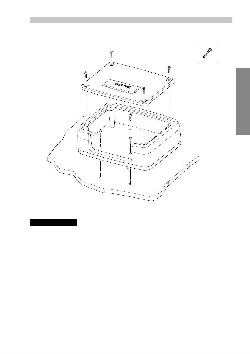
Network Installation / Installation du circuit
g
X3
English/Fran
çais
Note /Remarque:
Do not install the Crossover network where it will be exposed to moisture such as
under the floor mat or near the air conditioner. This may cause a malfunction./
Ne pas installer le circuit répartiteur dans un endroit où il sera exposé à l’humidité,
comme sous la moquette ou près du climatiseur. Cela risque de provoquer un mauvais
fonctionnement.
7
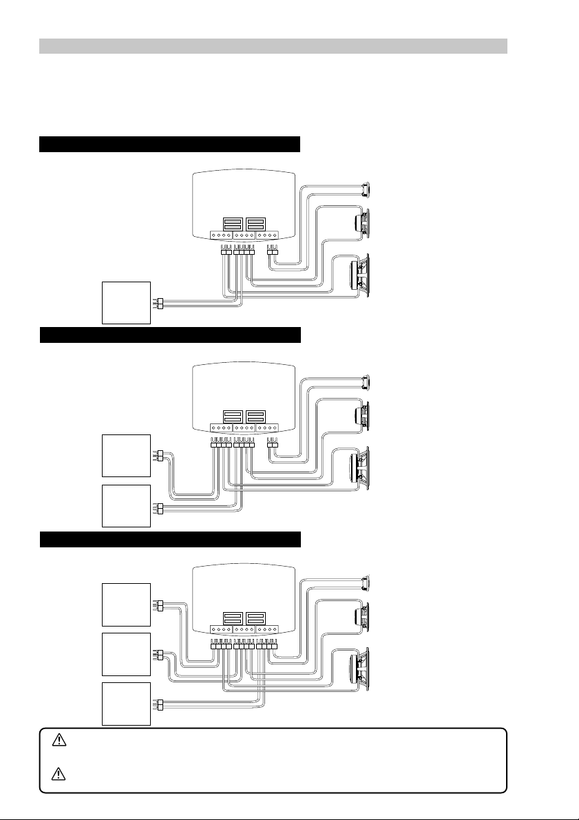
Network connections / Connexions du circuit
Insert the signal link jumpers highlighted in gray firmly following each connection example. If the
jumper is not connected properly as described, it might result in malfunction of amplifier.
Insérez fermement les cavaliers de liaison de signal soulignés en gris en suivant chaque exemple de
raccordement. Si le cavalier n’est pas relié correctement comme décrit, il pourrait avoir comme
conséquence le défaut de fonctionnement de l’amplificateur.
Connection Example 1 / Exemple de connexion 1
When connecting to single amp/single wiring / Lors du raccordement avec un seul amplificateur/
câblage simple.
WF/MID
MID/TW
SIGNAL
SIGNAL
LINK
LINK
+–+
–
Amplifier/
Amplificateur
Connection Example 2 / Exemple de connexion 2
When connecting to bi-amp/bi-wiring / Lors du raccordement avec deux amplificateurs/câblage
double.
WF/MID
MID/TW
SIGNAL
SIGNAL
LINK
LINK
+–+
–
Amplifier/
Amplificateur
Amplifier/
Amplificateur
Connection Example 3 / Exemple de connexion 3
When connecting to tri-amp/tri-wiring / Lors du raccordement avec trois amplificateurs/câblage triple.
WF/MID
SIGNAL
LINK
MID/TW
SIGNAL
LINK
+–+
–
Caution
Amplifier/
Amplificateur
Amplifier/
Amplificateur
Amplifier/
Amplificateur
Connect properly by following the manual. Otherwise it might result in fire or
accident.
Précaution
Reliez correctement en suivant le manuel. Autrement il pourrait avoir comme
conséquence le feu ou des accidents.
8

Crossover Network Introduction
It is common knowledge that the automotive interior is one of the most inhospitable
environments for high-fidelity sound, and that every vehicle poses its own unique set of
installation and acoustic challenges. While many of these problems can often be overcome with proper speaker placement, equalization, or other techniques, the attempt is
a time consuming task without guaranteed results. Yet with all these tools and methods
available, it is surprising to realize that one of the most powerful tuning tools has been
misunderstood or neglected by so many for so long. It is for this reason that Alpine has
developed the most advanced crossover network design in the history of car audio.
Much of the difference between demo-board and in-car performance can be attributed
to the fact that crossover networks have been traditionally tuned for only one specific
application – usually the demo-board. Without taking into account typical real world
installations, the transition between drivers and resultant frequency response will be
degraded for the majority of vehicles that installers are confronted with today. Through
Alpine’s unique phase coherent flat summation design methodology, however, it is now
possible to optimize performance for a variety of installations by intentionally altering
various filter characteristics. By achieving an “in-phase” condition between drivers in
the overlapping frequency range at the listening position, image smear, response aberrations and other typical problems can be dramatically reduced or eliminated altogether.
This “phase linkage” technique can be thought of as a kind of passive time correction in
the crossover region.
With Alpine’s introduction of such revolutionary processing technologies as digital time
correction and adaptive equalization, all of this may seem superlative. Unfortunately
however, such processing can significantly increase system complexity and therefore
may not be practical for every situation. Additionally, without careful use of time correction for each individual speaker in the system, integration problems between them can
remain. Subsequently, it may be advantageous to use such processing to compensate
for seating position bias in conjunction with the phase correction of the passive network
for the transition between individual drivers. Simply stated, the flexibility of the
AlpineF#1Status™ crossover network allows it to be a complimentary solution for achieving the best of both worlds, either as a stand alone solution or an integral component of
a partially active system.
English
As with all AlpineF#1Status™ products, it is the attention to the smallest details that
truly brings out ultimate performance... or in a word, MicroDynamics™. From the hand
coated crosscut wood fiber cones to the symmetric drive motor structures, nothing is
left to chance. This philosophy is carried throughout every aspect of the SPX-Z18T
speaker system, including the components, layout and design of the crossover network.
All series capacitors are the highest grade metalized polypropylene, and all series
inductors are heavy gauge air core. Even parallel inductors are of powder core construction, to maximize consistancy and sound quality. All elements are intentionally placed
in such a way to as to minimize any chance for magnetic or thermal influence, and all
signal path lengths are minimized with extra heavy circuit board traces. In the end, this
level of quality and attention to detail has but one purpose, to bring true sonic realism to
the automotive environment once and for all.
9
Jumper Group Function
Although recommendations are made for the most common system types in the following
pages, there are actually over 1000 unique and useful jumper combinations available for a
wide variety of vehicles, installations and personal tastes. While this flexibility has obvious
advantages, too many choices can also be confusing. Therefore, it will be helpful to understand the function of each jumper group in order to tune the network more effectively:
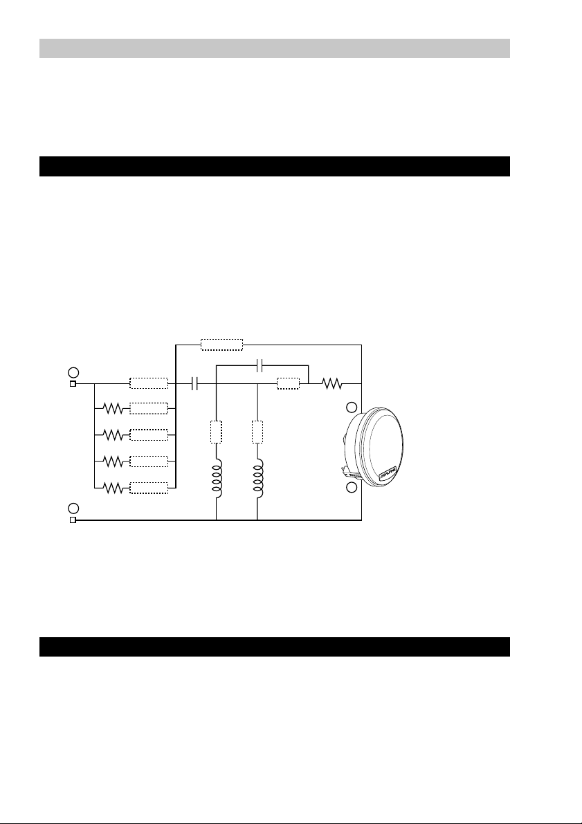
TW-HP:
In addition to functioning as a high-pass filter, this section also provides the necessary
adjustments for proper integration with the midrange. The transition between these two
drivers in the frequency and time domains is essential to the total performance of a
multi-element system, as it has a direct effect upon imaging, staging, focus
and tonal balance. In real world installations, distance and angle of both drivers relative
to the listener, their proximity to each other, and certainly the vehicle's interior also exert
additional influence. In anticipation of this, variations of filter slope, Q, cut-off frequency
and resultant phase shift are provided so that "phase linkage" and flat summation can
be maintained. As a general reference, the layout and available filter types of the tweeter
high-pass section are provided below:
BYPASS
+
R1
R2
R3
R4
+4dB/30°
+1.5dB/15°
0dB/0°
–1.5dB
–3dB
C1
L1 L2
–
HP-1
C2
HP-2
HP-3
R5
R1 = 1.5Ω
R2 = 3.3Ω
R3 = 4.7Ω
–
R4 = 5.6Ω
R5 = 0.5Ω
C1 = 3.3µF
C2 = 8.2µF
+
L1 = 0.65mH
L2 = 0.1mH
1st Order:
• No HP jumpers
• HP3
2nd Order:
• HP1 + HP2 + HP3
• HP1 + HP3
• HP2 + HP3
3rd Order:
• HP1
• HP2
• HP1 + HP2
TW LEVEL:
In general, this section provides precise level adjustment for optimum performance or
personal taste. However, it also allows for “tilting” of the filter frequency response in
order to compensate for the natural high frequency roll-off associated with off-axis listening angles. In other words, this jumper choice will have a direct effect on both Q and
cut-off frequency of the various filter combinations listed above. This effect can be seen
in the filter transfer function graphs for the various system types. If the TW-HP section is
set to bypass in favor of an electronic crossover, the off-axis feature will no longer function, but basic level adjustment will still be possible.
10
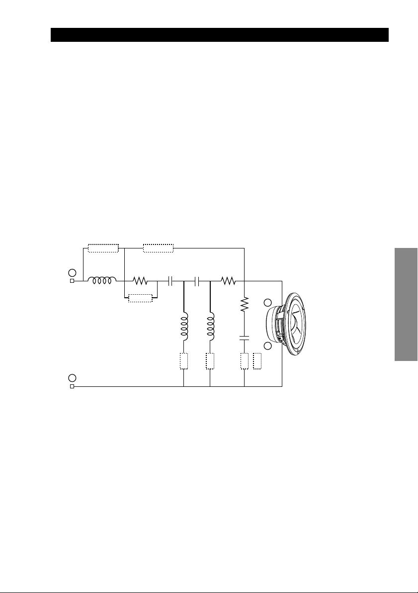
MID HP/LP:
As a selectable bandpass filter for the midrange, the net effect of this section is naturally
linked to the selections made in the tweeter high-pass and woofer low-pass sections.
Achieving the most phase coherent and flat summation possible requires controlling
the amount of inherent phase shift of each filter, and is directly related to the selection of
filter order, Q and cut-off frequency. Again, this relationship is also affected by the distance and angle of each driver relative to the listener and their proximity to each other.
Since the acoustic center of the midrange will be farther back than the tweeter in nearly
all applications, minimal delay is desirable in the midrange low-pass. Subsequently, this
filter is of low order, and leaves much of the adjustment capability for the mid/tweeter
transition to the tweeter high-pass section. For the midrange high-pass, higher order
configurations are used in most applications to achieve phase linkage with the woofer
(see WF-LP section). For general reference, the available midrange network configurations are listed below. In certain installations where positioning or placement necessitates level adjustment, a jumper is provided that boosts midrange output by approximately +2dB. As an additional note, either filter (high-pass or low-pass) may be bypassed independently for semi-active applications.
LP BYPASS
L3
+
+2dB
–
1st Order HP:
• No HP jumpers
• HP2 (semi-2nd Order)
1st Order LP:
• LP1
• LP2
HP BYPASS
C3R6
C4 R7
L4 L5
HP-1
3rd Order HP:
• HP1
HP-2
R8
C5
LP-2
LP-1
4th Order HP:
• HP1 + HP2
R6 = 1.0Ω
R7 = 1.0Ω
+
R8 = 22Ω
English
C3 = 18µF
C4 = 33µF
–
C5 = 10µF
L3 = 0.32mH
L4 = 2.0mH
L5 = 2.9mH
11
Jumper Group Function
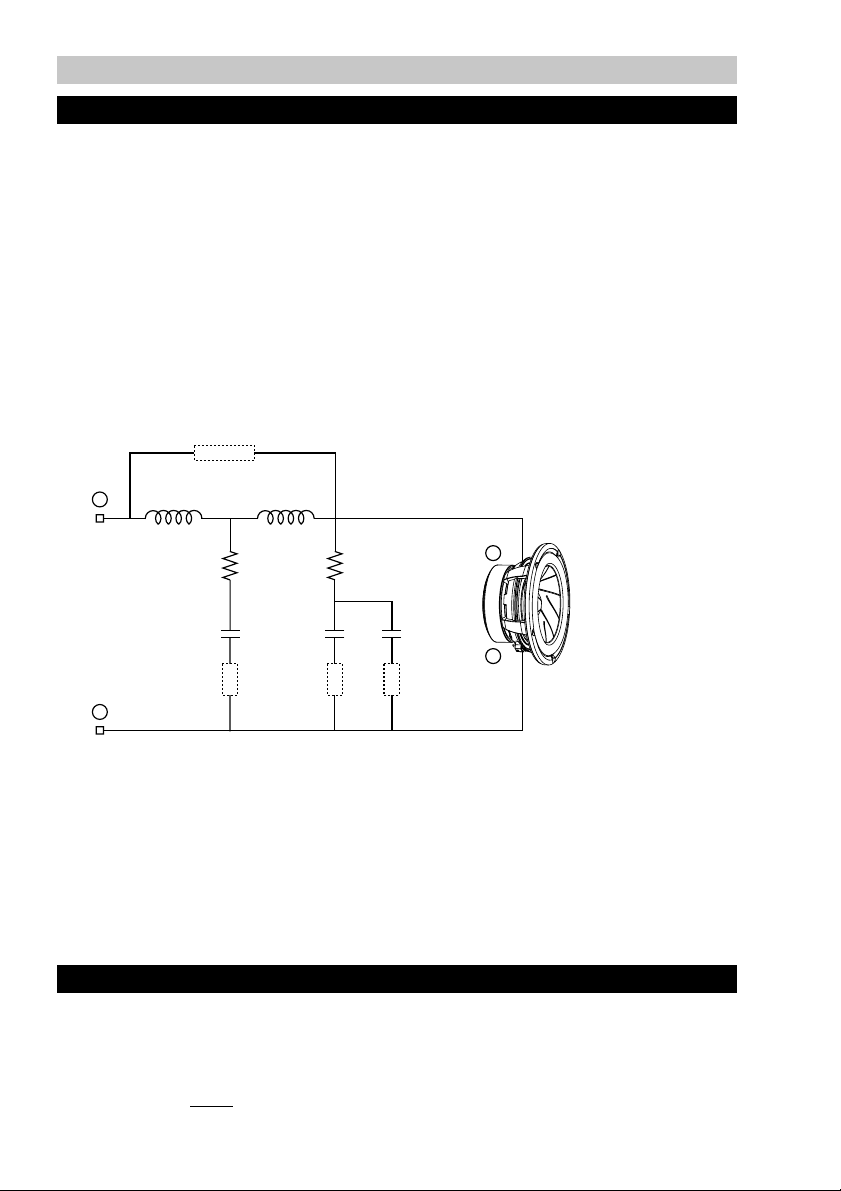
WF-LP:
While functioning as a low-pass filter for the woofer, this section also provides a wide
degree of adjustments for optimizing performance and system integration. Since it is
often difficult to position the woofer and midrange close together or at equal distances,
it is critical to achieve phase linkage between them to avoid localization, image smear,
poor staging, etc. Additionally, vehicle interior dimensions are typically close to the wavelength of the woofer/midrange crossover region, so it may be necessary to minimize
overlap to reduce the chance of generating a complex canceling sound field or response aberrations. Therefore, a variety of higher order filter types and characteristics
are provided in this section, making it possible to link the two drivers in relative phase
for a smooth transition in many applications. Again, it is important to note that the selections made in both the WF-LP and MID-HP sections produce a net effect, and must be
set in such a way so as to work together. As a general reference, the available woofer
low-pass filter configurations are listed below.
BYPASS
+
L6 L7
R9 = 2.2Ω
R10R9
+
R10 = 1.5Ω
C6 = 100µF
C7 = 47µF
LP-1
C7C6 C8
LP-3
LP-2
–
C8 = 220µF
L6 = 0.65mH
L7 = 0.65mH
–
1st Order:
• No HP jumpers
2nd Order:
• LP2
• LP3
• LP2 + LP3
3rd Order:
• LP1
4th Order:
• LP1 + LP2
• LP1 + LP3
• LP1 + LP2 + LP3
SIGNAL LINK:
The signal link jumpers provide a parallel connection between the input sides of the
terminal blocks, eliminating the need for extra terminals or wiring when using a single or
dual input.
Caution:
These jumpers
must be removed accordingly when used in a bi-amp or tri-amp
configuration to prevent possible damage to amplifiers.
12
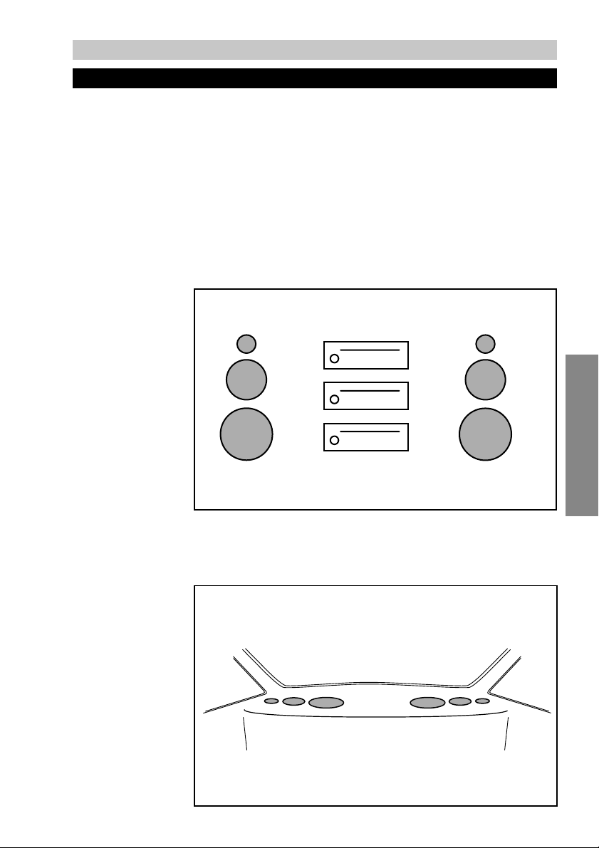
System Type 1
System Description
With all three drivers mounted close together and equidistant to the listening position,
this is surely the most favorable configuration for a component speaker system. Although such an installation may not often be practical in situations other than the demoboard, it is certainly possible given the custom fabrication techniques available today. In
anticipation this, a degree of tolerance is built into the settings described below for the
most likely cases, though some experimentation may be necessary if all conditions
cannot be met. If choosing to go beyond the recommended settings or utilizing the
network in a partially active mode, keep in mind that phase coherence and flat summation remains critical even in the idyllic flat baffle situation, as each driver type exhibits
unique phase and group delay characteristics.
• Type-1A is the
default setting of the
network, and
assumes essentially
on-axis positioning
and equal
pathlength of all
drivers relative to
the listening
position.
English
• Type-1B
cases where
pathlength is
nearly the same to
all drivers, but
where the mounting surface
orientation creates
a uniform but fairly
extreme off-axis
listening angle.
is for such
13
 Loading...