


PKG-M780
DUAL 7” HEADREST MONITOR PACKAGE FOR REAR SEAT ENTERTAINMENT
• OWNER’S MANUAL
Please read before using this equipment.
• MODE D’EMPLOI
Veuillez lire avant d’utiliser cet appareil.
• MANUAL DE OPERACIÓN Léalo antes de utilizar este equipo.
EN
FR
ES
ALPINE ELECTRONICS, INC. |
ALPINE ELECTRONICS OF AUSTRALIA PTY. LTD. |
ALPINE ELECTRONICS FRANCE S.A.R.L. |
|
Tokyo office: 1-1-8 Nishi Gotanda, |
6-8 Fiveways Boulevarde Keysborough, |
(RCS PONTOISE B 338 101 280) |
|
Shinagawa-ku, |
Victoria 3173, Australia |
98, Rue De La Belle Etoile, Z.I. Paris Nord Il |
|
Tokyo 141-8501, Japan |
Tel.: (03) 9769-0000 |
B.P. 50016 F-95945, Roissy, Charles De Gaulle |
|
Tel.: (03) 3494-1101 |
ALPINE ELECTRONICS GmbH |
Cedex, France |
|
ALPINE ELECTRONICS OF AMERICA, INC. |
Tel.: 01-48 63 89 89 |
||
Frankfurter Ring 117 80807 Munich, Germany |
|||
ALPINE ELECTRONICS OF U.K., LTD. |
|||
19145 Gramercy Place, Torrance, |
Tel.: 089-32 42 640 |
||
California 90501, U.S.A. |
ALPINE ITALIA S.p.A. |
13 Tanners Drive, Blakelands, Milton Keynes |
|
Tel.: 1-800-ALPINE-1 (1-800-257-4631) |
MK14 5BU, U.K. |
||
Via C. Colombo 8, 20090 Trezzano Sul Naviglio |
|||
ALPINE ELECTRONICS OF CANADA, INC. |
Tel.: 01908-61 15 56 |
||
MI, Italy |
|||
ALPINE ELECTRONICS DE ESPAÑA, S.A. |
|||
Suite 203, 7300 Warden Ave. Markham, |
Tel.: 02-48 47 81 |
||
Ontario L3R 9Z6, Canada |
ALPINE ELECTRONICS (BENELUX) GmbH |
Portal De Gamarra 36, Pabellón 32 |
|
Tel.: 1-800-ALPINE-1 (1-800-257-4631) |
01013 Vitoria (Alava)-Apdo. 133, Spain |
||
Leuvensesteenweg 510-B6, |
|||
|
Tel.: 34-45-283588 |
||
|
1930 Zaventem, Belgium |
||
|
|
||
|
Tel.: 02-725 1315 |
|
(1*/,6+
Contents
Operating Instructions |
|
WARNING |
|
WARNING .................................................. |
2 |
CAUTION ................................................... |
3 |
PRECAUTIONS ......................................... |
3 |
Basic Operation |
|
Screen Display ON/OFF .................................... |
4 |
Adjusting the Volume ......................................... |
4 |
Switching the Source ......................................... |
4 |
Switching the display mode ............................... |
4 |
Adjusting ............................................................ |
5 |
Other Useful Feature |
|
Remote Control Sensor ...................................... |
6 |
Wireless Headphone |
|
Headphone Receivers......................................... |
6 |
Information |
|
In Case of Difficulty .......................................... |
7 |
Specifications ..................................................... |
7 |
PKG-M780 includes:
Installation and Connections
Warning ............................................................. |
8 |
Caution .............................................................. |
8 |
Precautions ........................................................ |
9 |
Installation ...................................................... |
10 |
Connections .................................................... |
11 |
•TME-M780 (7” Wide VGA LCD Monitor): 2 units
•SHS-N205 (Dual Source Fold-Flat IR Headphone): 2 pairs
•Headrest Installation Kit: 2 units
•AV Control Black Box: 1 unit
PKG-M780 is designed only for the purpose of rear seat entertainment. This product must not be installed anywhere else except on the back of the headrest.

 WARNING
 WARNING
This symbol means important instructions. Failure to heed them can result in serious injury or death.
DO NOT OPERATE ANY FUNCTION THAT TAKES YOUR ATTENTION AWAY FROM SAFELY DRIVING YOUR VEHICLE.
Any function that requires your prolonged attention should only be performed after coming to a complete stop. Always stop the vehicle in a safe location before performing these functions. Failure to do so may result in an accident.
KEEP THE VOLUME AT A LEVEL WHERE YOU CAN STILL HEAR OUTSIDE NOISE WHILE DRIVING.
Failure to do so may result in an accident.
MINIMIZE DISPLAY VIEWING WHILE DRIVING.
Viewing the display may distract the driver from looking ahead of the vehicle and cause an accident.
DO NOT DISASSEMBLE OR ALTER.
Doing so may result in an accident, fire or electric shock.
USE THIS PRODUCT FOR MOBILE 12V APPLICATIONS.
Use for other than its designed application may result in fire, electric shock or other injury.
KEEP SMALL OBJECTS SUCH AS BATTERY OUT OF THE REACH OF CHILDREN.
Swallowing them may result in serious injury. If swallowed, consult a physician immediately.
USE THE CORRECT AMPERE RATING WHEN
REPLACING FUSES.
Failure to do so may result in fire or electric shock.
DRIVER MUST NOT WATCH VIDEO WHILE DRIVING.
Watching the video may distract the driver from looking ahead of the vehicle and cause an accident.
INSTALL THE PRODUCT CORRECTLY SO THAT THE DRIVER CANNOT WATCH TV/VIDEO UNLESS THE VEHICLE IS STOPPED.
It is dangerous (and illegal in many states) for the driver to watch TV/Video while driving a vehicle. Installing this product incorrectly enables the driver to watch TV/Video while driving. This may cause a distraction, preventing the driver from looking ahead, thus causing an accident. The driver or other people could be severely injured.

 CAUTION
This symbol means important instructions. Failure to heed them can result in injury or material property damage.
HALT USE IMMEDIATELY IF A PROBLEM APPEARS.
Failure to do so may cause personal injury or damage to the product. Return it to your authorized Alpine dealer or the nearest Alpine Service Centre for repairing.
 PRECAUTIONS
Temperature
Be sure the temperature inside the vehicle is between +45°C (+113°F) and 0°C (+32°F) before turning your unit on.
Fuse Replacement
When replacing the fuse(s), the replacement must be of the same amperage as shown on the fuse holder. If the fuse(s) blows more than once, carefully check all electrical connections for shorted circuitry. Also have your vehicle’s voltage regulator checked.
Maintenance
If you have problems, do not attempt to repair the unit yourself. Return it to your Alpine dealer or the nearest Alpine Service Station for servicing.
Installation Location
Make sure the TME-M780 & SHS-N205 will not be exposed to:
•Direct sun and heat
•High humidity
•Excessive dust
•Excessive vibrations
•After turning the system off, a slight ghost of the image will remain temporarily. This is an effect peculiar to LCD technology and is normal.
•Under cold temperature conditions, the screen may lose contrast temporarily. After a short warm-up period, it will return to normal.
Basic Operation
|
|
|
|
|
|
|
|
|
|
|
|
DISP |
|
|
POWER |
||
|
|
|
SELECT |
||
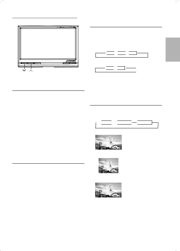
Screen Display ON/OFF
1 Press the POWER button.
2To turn off the POWER, press the POWER button again.
•If properly connected, the monitors main POWER will turn off when the vehicle's ignition switch is off.
•After turning the system off, a slight ghost of the image will remain temporarily. This is an effect peculiar to LCD technology and is normal.
•Under cold temperature conditions, the screen may lose contrast temporarily. After a short warm-up period, it will return to normal.
Adjusting the Volume
1Adjust the volume level by pressing the  or
or  button.
Switching the Source
Press the SELECT button.
Each press of the button will cycle through the modes as follows:
1If AUX3 SELECTION S/W of Black Box is
• "IN" position
 AUX1
AUX1 

 AUX2
AUX2 

 AUX3
AUX3
•"OUT" position
 AUX1
AUX1

 AUX2
AUX2
2If current screen mode is AUX3, and AUX3 SELECTION S/W is switched to "OUT" then screen mode will be changed AUX1.
Switching the display mode
1Press the DISP button.
Each press of the button will cycle through the modes as follows.

 WIDE
WIDE 

 NORMAL
 ZOOM
ZOOM
|
|
Normal images are |
|
|
expanded uniformly in |
|
|
the horizontal direction |
|
|
and are displayed over |
|
|
the entire screen. |
|
WIDE |
|
|
|
|
|
|
Normal image (4:3) |
|
|
|
|
|
|
|
NORMAL |
|
|
|
Normal images are |
|
|
expanded in the |
|
|
horizontal direction and |
|
|
are displayed over the |
|
|
entire screen. The |
|
ZOOM |
|
|
expansion ratio |
|
|
|
|
|
|
increases towards the |
|
|
right and left edges of |
|
|
the screen. |
Basic Operation
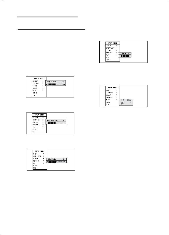
Adjusting
1Press and hold the DISP button for at least 2 seconds.
Adjustment screen will appear.
2Press the DISP button and select the mode to be adjusted.
Adjust by pressing the  or
or  button.
DISP : Selects the mode. (downward)  or
or  : Adjusts.
1 Brightness adjustment (BRIGHT)
Allows the brightness (0 to 63) of the picture
2 Contrast adjustment (CONTRAST)
Contrast can be adjusted from 0 to 63
3 Color depth adjustment (COLOR)
Color depth can be adjusted from 0 to 63
4 Dimmer adjustment (DIMMER)
The backlighting is set to the value adjusted at 0~15.
5 IR-TX adjustment (IR-TX)
ON : Enable to use IR Headphone
6Reset
Press  or
or  to restore system setting to factory detault.
7Exit
Select EXIT to exit setup menu, and the screen will return to normal mode.
3After completing adjustments, press and hold the DISP button for at least 2 seconds.
The screen will return to the normal mode.
•If no operation is made for 5 seconds after selecting a mode to be adjusted, the adjustment mode will be cleared.
Other Useful Feature
Remote Control Sensor |
|
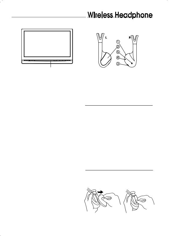
SHS-N205 Headphone Receivers |
|
|
|
|
|
|
|
|
|
|
|
|
Remote sensor
•Receives the remote control signal from connected ALPINE products such as DVD players and TV tuners.
1) SOURCE A/B SWITCH
2) BATTERY COVER
3) VOLUME CONTROL
4) POWER SWITCH
5) POWER INDICATOR LED
Operation
Please Read Carefully to Prevent Damage to the Headphones or your Ears:
WARNING: Before turning on the power, remove headphones and turn the volume down as low as possible.
1) Be sure batteries are properly installed in the headphones
2) Turn the headphone volume completely down before placing it on your ears and turning on the power.
3) Turn on the headphone power and adjust the headphone volume to a comfortable level (You can increase the audio source volume if needed).
Battery installation
1) Place two AAA batteries into the battery Compartment of the Headphone(s), making sure that the battery polarity is correct.

Information
In Case of Difficulty
If you encounter a problem, please review the items in the following checklist. This guide will help you isolate the problem if the unit is at fault. Otherwise, make sure the rest of your system is properly connected or consult your authorized Alpine dealer.
No function or display.
•Car's ignition is off.
-Turn the ignition on.
•No fuse or blown fuse.
-Check the cause and replace the fuse.
•Incorrect connections.
-Check connection and remedy.
•Vehicle's battery is weak.
-Check the voltage of vehicle's battery.
No picture display.
•Brightness control is set for minimum brightness control.
-Adjust the brightness.
•Incorrect setting of the VTR mode.
-Switch to the correct mode.
•Protective circuit is on because of high temperature.
-Wait until the temperature inside the vehicle comes down to the operating temperature range (45°C).
•Incorrect or open connection with the Monitor, AV interface unit.
-Check the connection and remedy.
Picture color is poor.
•Brightness/Color/Tint control are not set to the proper positions.
-Check each control.
Spots or dotted lines/stripes appear.
•Caused by neon signs, high-voltage power lines, CB transmitter, other vehicle's ignition plugs, etc.
-Change the location of your vehicle.
Unit does not operate.
•Monitor's power is not turned on.
-Turn on the monitor's power.
Information
Specifications
MONITOR
Screen Size |
7.0-type |
Display System |
Low reflection rear |
|
projection type TN liquid |
|
crystal panel |
Drive System |
Active matrix drive, |
|
normally white display |
Number of Picture Elements |
800(W) x 480(H) x 3 |
|
1,152M pixels (VGA) |
Effective Number of Picture Elements |
99.99% or more |
Light Source |
Internal optical system |
|
(U-type cold cathode |
|
fluorescent tube) |
Dimensions (W x H x D) |
173 x 118.5 x 19.5mm |
Weight |
500g |
Black box
Dimensions (W x H x D) |
177 x 103 x 28 mm |
Weight |
400g |
•Due to continuous product improvement, specifications and design are subject to change without notice.
•The LCD panel is manufactured using an extremely high precision manufacturing technology. Its effective pixel ratio is over 99.99%. This means that there is a possibility that 0.01% of the pixels could be either always ON or OFF.

Installation and Connections
Before installing or connecting the unit, please read the following and pages 2 and 3 of this manual thoroughly for proper use.
 Warning
MAKE THE CORRECT CONNECTIONS.
Failure to make the proper connections may result in fire or product damage.
USE ONLY IN CARS WITH A 12 VOLT NEGATIVE GROUND.
(Check with your dealer if you are not sure.) Failure to do so may result in fire, etc.
BEFORE WIRING, DISCONNECT THE CABLE FROM THE NEGATIVE BATTERY TERMINAL.
Failure to do so may result in electric shock or injury due to electrical shorts.
DO NOT ALLOW CABLES TO BECOME ENTANGLED IN SURROUNDING OBJECTS.
Arrange wiring and cables in compliance with the manual to prevent obstructions when driving. Cables or wiring that obstruct or hang up on places such as the steering wheel, shift lever, brake pedals, etc. can be extremely hazardous.
DO NOT SPLICE INTO ELECTRICAL CABLES.
Never cut away cable insulation to supply power to other equipment. Doing so will exceed the current carrying capacity of the wire and result in fire or electric shock.
DO NOT USE BOLTS OR NUTS IN THE BRAKE OR STEERING SYSTEMS TO MAKE GROUND CONNECTIONS.
Bolts or nuts used for the brake or steering systems (or any other safety-related system), or tanks should NEVER be used for installations or ground connections. Using such parts could disable control of the vehicle and cause fire etc.
KEEP SMALL OBJECTS SUCH AS BATTERY OUT OF THE REACH OF CHILDREN.
Swallowing them may result in serious injury. If swallowed, consult a physician immediately.
DO NOT INSTALL IN LOCATIONS WHICH MIGHT HINDER VEHICLE OPERATION, SUCH AS THE STEERING WHEEL OR SHIFT LEVER.
Doing so may obstruct forward vision or hamper movement etc. and results in serious accident.
DO NOT DAMAGE PIPE OR WIRING WHEN DRILLING HOLES.
When drilling holes in the chassis for installation, take precautions so as not to contact, damage or obstruct pipes, fuel lines, tanks or electrical wiring. Failure to take such precautions may result in fire.
DO NOT INSTALL THE MONITOR NEAR THE PASSENGER SEAT AIR BAG.
If the unit is not installed correctly the air bag may not function correctly and when triggered the air bag may cause the monitor to spring upwards causing an accident and injuries.
 Caution
HAVE THE WIRING AND INSTALLATION DONE BY EXPERTS.
The wiring and installation of this unit requires special technical skill and experience. To ensure safety, always contact the dealer where you purchased this product to have the work done.
USE SPECIFIED ACCESSORY PARTS AND INSTALL THEM SECURELY.
Be sure to use only the specified accessory parts. Use of other than designated parts may damage this unit internally or may not securely install the unit in place. This may cause parts to become loose resulting in hazards or product failure.
ARRANGE THE WIRING SO IT IS NOT CRIMPED OR PINCHED BY A SHARP METAL EDGE.
Route the cables and wiring away from moving parts (like the seat rails) or sharp or pointed edges. This will prevent crimping and damage to the wiring. If wiring passes through a hole in metal, use a rubber grommet to prevent the wire’s insulation from being cut by the metal edge of the hole.
DO NOT INSTALL IN LOCATIONS WITH HIGH MOISTURE OR DUST.
Avoid installing the unit in locations with high incidence of moisture or dust. Moisture or dust that penetrates into this unit may result in product failure.

Precautions
•Be sure to disconnect the cable from the (–) battery post before installing your TME-M780.
This will reduce any chance of damage to the unit case of a short-circuit.
•Be sure to connect the color coded leads according to the diagram. Incorrect connections may cause the unit to malfunction or damage the vehicle's electrical system.
•When making connections to the car’s electrical system, be aware of the factory installed components (e.g. on-board computer). Do not tap into these leads to provide power for this unit. When connecting the TME-M780 to the fuse box, make sure the fuse for the intended circuit of the TME-M780 has the appropriate amperage. Failure to do so may result in damage to the unit and/or the vehicle. When in doubt, consult your ALPINE dealer.
•The TME-M780 uses female RCA-type jacks for connection to other units having RCA connectors. You may need an adaptor to connect other units. If so, please contact your authorized TME-M780 dealer for assistance.
IMPORTANT
Please record the serial number of your unit in the space provided below and keep it as a permanent record. The serial number plate is located on the rear of the monitor or on the bottom of the AV interface unit.
SERIAL NUMBER:
INSTALLATION DATE:
INSTALLATION TECHNICIAN:
PLACE OF PURCHASE:
Installation and Connections
Installation
Installing AV Control Black Box
This Unit can be placed inside the trunk, on the kick panel of the front passenger's seat or underdash. However, to avoid unnecessary signal wiring, it is better to mount the Unit as close as possible to the Display.
DO NOT MOUNT THE INTERFACE UNIT IN LOCATIONS EXPOSED TO MOISTURE OR EXTREME HEAT (such as the engine compartment).
Mounting with screws
1.Place the unit on the location chosen for installation.
2.Mark the screw locations using the unit as a template.
3.Drill a hole less than 3 mm in diameter.
 WARNING
When you are drilling a hole in the car body, be careful not to damage pipes, tanks or electrical wiring etc.. It might cause an accident or a fire.
4.Firmly attach the unit using 4 of the supplied selftapping screws (M4 x 15).
Self-tapping screws (M4 x 15)

Connections
Make connections correctly.
Improper connections may cause a fire or operation failure.
Basic connection
TME-M780 A |
TME-M780 B |
Monitor 1 |
Monitor 2 |
 Loading...