


 Loading...
Part No. 060390-10, Rev. D
September 2016
OmniSwitch 6860/6860E
Hardware Users Guide
enterprise.alcatel-lucent.com

This user guide documents OmniSwitch 6860/6860E hardware, including chassis and associated components. The specifications described in this guide are subject to change without notice.
enterprise.alcatel-lucent.com
Alcatel-Lucent and the Alcatel-Lucent Enterprise logo are trademarks of Alcatel-Lucent. To view other trademarks used by affiliated companies of ALE Holding, visit: enterprise.alcatel-lucent.com/trademarks. All other trademarks are the property of their respective owners. The information presented is subject to change without notice. Neither ALE Holding nor any of its affiliates assumes any responsibility for inaccuracies contained herein. (July 2015)
26801 West Agoura Road
Calabasas, CA 91301
(818) 880-3500 FAX (818) 880-3505
Service & Support Contact Information
North America: 800-995-2696
Latin America: 877-919-9526
EMEA: +800 00200100 (Toll Free) or +1(650)385-2193
Asia Pacific: +65 6240 8484
Web: support.esd.alcatel-lucent.com
Email: ebg_global_supportcenter@al-enterprise.com

Contents
|
About This Guide .......................................................................................................... |
ix |
|
Supported Platforms .......................................................................................................... |
ix |
|
Who Should Read this Manual? ........................................................................................ |
ix |
|
When Should I Read this Manual? .................................................................................... |
ix |
|
What is in this Manual? ...................................................................................................... |
x |
|
What is Not in this Manual? ............................................................................................... |
x |
|
How is the Information Organized? ................................................................................... |
x |
|
Documentation Roadmap .................................................................................................. |
xi |
|
Related Documentation ................................................................................................... |
xiii |
|
Technical Support ........................................................................................................... |
xiv |
Chapter 1 |
OmniSwitch 6860 ...................................................................................................... |
1-1 |
|
OmniSwitch 6860 Availability Features ......................................................................... |
1-3 |
|
Power Supply Redundancy ...................................................................................... |
1-3 |
|
Hot-Swapping ........................................................................................................... |
1-3 |
|
Hardware Monitoring ............................................................................................... |
1-4 |
Chapter 2 |
Getting Started ........................................................................................................... |
2-1 |
|
Installing the Hardware ................................................................................................... |
2-1 |
|
Items Required ......................................................................................................... |
2-1 |
|
Site Preparation ........................................................................................................ |
2-1 |
|
Environmental Requirements ............................................................................ |
2-1 |
|
Electrical Requirements ..................................................................................... |
2-1 |
|
Electrical Surge Warning .................................................................................. |
2-2 |
|
Unpacking and Installing the Switch ....................................................................... |
2-3 |
|
Items Included ................................................................................................... |
2-3 |
|
Weight Considerations ...................................................................................... |
2-3 |
|
Airflow Considerations ..................................................................................... |
2-4 |
|
Mounting the Switch ....................................................................................................... |
2-4 |
|
Connections and Cabling ................................................................................................ |
2-5 |
|
Network Cable Installation Warning ................................................................. |
2-5 |
|
Serial Connection to the Console Port ............................................................... |
2-5 |
|
Serial Connection Default Settings ................................................................... |
2-5 |
|
Ethernet Management Port (EMP) Cable Requirements ......................................... |
2-5 |
|
Booting the Switch .......................................................................................................... |
2-6 |
|
Component LEDs .............................................................................................. |
2-6 |
OmniSwitch 6860 Hardware Users Guide September 2016 |
iii |

|
|
Contents |
|
|
|
|
|
|
|
Your First Login Session ................................................................................................ |
2-7 |
|
Logging In to the Switch .......................................................................................... |
2-7 |
|
Setting IP Address Information for the EMP ........................................................... |
2-8 |
|
Unlocking Session Types ......................................................................................... |
2-9 |
|
Changing the Login Password .................................................................................. |
2-9 |
|
Setting the System Time Zone ............................................................................... |
2-10 |
|
Setting the Date and Time ...................................................................................... |
2-10 |
|
Setting Optional Parameters ................................................................................... |
2-10 |
|
Specifying an Administrative Contact ............................................................. |
2-10 |
|
Specifying a System Name .............................................................................. |
2-10 |
|
Specifying the Switch’s Location .................................................................... |
2-10 |
|
Viewing Your Changes .......................................................................................... |
2-11 |
|
Saving Your Changes ............................................................................................. |
2-11 |
Chapter 3 |
Chassis and Power Supplies .................................................................................... |
3-1 |
|
OmniSwitch 6860 Chassis Details .................................................................................. |
3-2 |
|
Basic Models - Non-PoE .......................................................................................... |
3-2 |
|
OS6860-24 Front Panel ..................................................................................... |
3-2 |
|
OS6860-24 Rear Panel ...................................................................................... |
3-2 |
|
OS6860-24 Chassis Specifications ........................................................................... |
3-3 |
|
OS6860-48 Front Panel ..................................................................................... |
3-4 |
|
OS6860-48 Rear Panel ...................................................................................... |
3-4 |
|
OS6860-48 Chassis Specifications ........................................................................... |
3-5 |
|
Basic Models - PoE .................................................................................................. |
3-6 |
|
OS6860-P24 Front Panel ................................................................................... |
3-6 |
|
OS6860-P24 Rear Panel .................................................................................... |
3-6 |
|
OS6860-P24 Chassis Specifications ........................................................................ |
3-7 |
|
OS6860-P48 Front Panel ................................................................................... |
3-8 |
|
OS6860-P48 Rear Panel .................................................................................... |
3-8 |
|
OS6860-P48 Chassis Specifications ........................................................................ |
3-9 |
|
Enhanced Models - Non-PoE ................................................................................. |
3-10 |
|
OS6860E-24 Front Panel ................................................................................. |
3-10 |
|
OS6860E-24 Rear Panel .................................................................................. |
3-10 |
|
OS6860E-24 Chassis Specifications ...................................................................... |
3-11 |
|
OS6860E-48 Front Panel ................................................................................. |
3-12 |
|
OS6860E-48 Rear Panel .................................................................................. |
3-12 |
|
OS6860E-48 Chassis Specifications ...................................................................... |
3-13 |
|
OS6860E-U28 Front Panel .............................................................................. |
3-14 |
|
OS6860E-U28 Rear Panel ............................................................................... |
3-14 |
|
OS6860E-U28 Chassis Specifications ................................................................... |
3-15 |
|
Enhanced Models - PoE ......................................................................................... |
3-16 |
|
OS6860E-P24 Front Panel .............................................................................. |
3-16 |
|
OS6860E-P24 Rear Panel ................................................................................ |
3-16 |
|
OS6860E-P24 Chassis Specifications .................................................................... |
3-17 |
|
OS6860E-P48 Front Panel .............................................................................. |
3-18 |
|
OS6860E-P48 Rear Panel ................................................................................ |
3-18 |
|
OS6860E-P48 Chassis Specifications .................................................................... |
3-19 |
|
Chassis Status LEDs ............................................................................................... |
3-19 |
iv |
OmniSwitch 6860 Hardware Users Guide September 2016 |

Contents
|
|
|
|
.....................................................................................................Mounting the Switch |
3-21 |
General Mounting Recommendations .................................................................... |
3-21 |
Airflow Recommendations .................................................................................... |
3-22 |
Blank Cover Panels ................................................................................................ |
3-23 |
Installing Blank Cover Panels ......................................................................... |
3-23 |
Rack-Mounting ............................................................................................................. |
3-24 |
Installing Rack Mount Flanges .............................................................................. |
3-24 |
Installing the Chassis In the Rack .......................................................................... |
3-26 |
Standalone (Non-Rack Mounted) Installations ...................................................... |
3-27 |
Power Supplies .............................................................................................................. |
3-28 |
Dying Gasp ............................................................................................................. |
3-29 |
Scenarios .......................................................................................................... |
3-29 |
SNMP Trap ...................................................................................................... |
3-29 |
Syslog Message ............................................................................................... |
3-29 |
OS6860-BP 150W Power Supply .......................................................................... |
3-30 |
OS6860-BP LED States .................................................................................. |
3-30 |
OS6860-BP-D 150W DC Power Supply ............................................................... |
3-31 |
OS6860-BP-D LED States .............................................................................. |
3-31 |
OS6860-BP-PH 600W Power Supply .................................................................... |
3-32 |
OS6860-BP-PH LED States ............................................................................ |
3-32 |
OS6860-BP-PX 920W Power Supply .................................................................... |
3-33 |
OS6860-BP-PX LED States ............................................................................ |
3-33 |
DC Power Supply Connections .............................................................................. |
3-34 |
Connecting a DC Cable Harness to the Chassis Power Supply ...................... |
3-34 |
Connecting a DC Cable Harness to the DC Power Source ............................. |
3-34 |
Installing Power Supplies ....................................................................................... |
3-35 |
Removing Power Supplies ..................................................................................... |
3-37 |
Grounding the Chassis .................................................................................................. |
3-39 |
OS6860 FANTRAY NONPOE Fan Tray ..................................................................... |
3-40 |
OS6860 FANTRAY NONPOE LED States .......................................................... |
3-40 |
Monitoring Chassis Components .................................................................................. |
3-41 |
Viewing Chassis Slot Information ......................................................................... |
3-41 |
Monitoring Chassis Temperature .................................................................................. |
3-41 |
Temperature Errors .......................................................................................... |
3-42 |
OmniSwitch 6860 Hardware Users Guide September 2016 |
v |

|
Contents |
|
|
|
|
|
|
|
Chapter 4 |
Managing Power over Ethernet (PoE) ................................................................. |
4-1 |
|
In This Chapter ................................................................................................................ |
4-2 |
|
Power over Ethernet Specifications ................................................................................ |
4-3 |
|
Viewing Power Supply Status .................................................................................. |
4-3 |
|
Viewing PoE Status .................................................................................................. |
4-4 |
|
Power over Ethernet Defaults ......................................................................................... |
4-4 |
|
Understanding and Modifying the Default Settings ................................................. |
4-5 |
|
PoE Class Detection ................................................................................................. |
4-5 |
|
PoE Operational Status ............................................................................................. |
4-5 |
|
Configuring the Total Power Available to a Port .............................................. |
4-6 |
|
Configuring the Total Power Available to a slot ............................................... |
4-6 |
|
Setting Port Priority Levels ............................................................................... |
4-7 |
|
Setting the Capacitor Detection Method ........................................................... |
4-7 |
|
Understanding Priority Disconnect ................................................................................. |
4-8 |
|
Setting Priority Disconnect Status ............................................................................ |
4-8 |
|
Disabling Priority Disconnect ........................................................................... |
4-8 |
|
Enabling Priority Disconnect ............................................................................ |
4-8 |
|
Priority Disconnect is Enabled; Same Priority Level on All PD ....................... |
4-9 |
|
Priority Disconnect is Enabled; Incoming PD Port has Highest Priority Level 4-9 |
|
|
Priority Disconnect is Enabled; Incoming PD Port has Lowest Priority Level |
4-9 |
|
Priority Disconnect is Disabled ....................................................................... |
4-10 |
|
Monitoring Power over Ethernet via CLI ..................................................................... |
4-11 |
Appendix A |
Regulatory Compliance and Safety Information................................................ |
A-1 |
|
Declaration of Conformity: CE Mark ............................................................................ |
A-1 |
|
Waste Electrical and Electronic Equipment (WEEE) Statement ............................ |
A-1 |
|
China RoHS: Hazardous Substance Table ....................................................... |
A-2 |
|
California Proposition 65 Warning .................................................................. |
A-2 |
|
Standards Compliance .................................................................................................... |
A-3 |
|
FCC Class A, Part 15 .............................................................................................. |
A-5 |
|
Canada Class A Statement ...................................................................................... |
A-5 |
|
JATE ........................................................................................................................ |
A-5 |
|
CISPR22 Class A warning ...................................................................................... |
A-5 |
|
Korea Emissions Statement ..................................................................................... |
A-6 |
|
VCCI ....................................................................................................................... |
A-6 |
|
Class A Warning for Taiwan and Other Chinese Markets ...................................... |
A-6 |
|
Class 1M Laser Warning ......................................................................................... |
A-6 |
|
Network Cable Installation Warning ....................................................................... |
A-6 |
|
Translated Safety Warnings ........................................................................................... |
A-7 |
|
Blank Panels Warning ...................................................................................... |
A-7 |
|
Electrical Storm Warning ................................................................................. |
A-7 |
|
Installation Warning ......................................................................................... |
A-7 |
|
Invisible Laser Radiation Warning ................................................................... |
A-8 |
|
Operating Voltage Warning ............................................................................. |
A-8 |
|
Power Disconnection Warning ......................................................................... |
A-8 |
|
Proper Earthing Requirement Warning ............................................................ |
A-9 |
vi |
OmniSwitch 6860 Hardware Users Guide September 2016 |

Contents
|
|
|
|
........................................................................DC Power Supply Connection Warning |
A-9 |
Read Important Safety Information Warning ................................................. |
A-10 |
Restricted Access Location Warning ............................................................. |
A-10 |
Wrist Strap Warning ....................................................................................... |
A-10 |
Instrucciones de seguridad en español ......................................................................... |
A-11 |
Advertencia sobre el levantamiento del chasis ............................................... |
A-11 |
Advertencia de las tapaderas en blanco .......................................................... |
A-11 |
Advertencia en caso de tormenta eléctrica ..................................................... |
A-11 |
Advertencia de instalación ............................................................................. |
A-11 |
Advertencia de radiación láser invisible ......................................................... |
A-11 |
Advertencia de la batería de litio .................................................................... |
A-11 |
Advertencia sobre la tensión de operación ..................................................... |
A-11 |
Advertencia sobre la desconexión de la fuente .............................................. |
A-11 |
Advertencia sobre una apropiada conexión a tierra ....................................... |
A-12 |
Leer “información importante de seguridad” ................................................. |
A-12 |
Advertencia de acceso restringido .................................................................. |
A-12 |
Advertencia de pulsera antiestática ................................................................ |
A-12 |
Clase de seguridad .......................................................................................... |
A-12 |
Advertencia de fuentes de poder .................................................................... |
A-12 |
OmniSwitch 6860 Hardware Users Guide September 2016 |
vii |
Contents
|
|
|
|
|
|
viii |
OmniSwitch 6860 Hardware Users Guide September 2016 |

About This Guide
This OmniSwitch 6860 Hardware Users Guide describes OmniSwitch 6860 switch components and basic switch hardware procedures.
Supported Platforms
The information in this guide applies only to OmniSwitch 6860 switches.
Who Should Read this Manual?
The audience for this users guide is network administrators and IT support personnel who need to configure, maintain, and monitor switches and routers in a live network. However, anyone wishing to gain knowledge of OmniSwitch 6860 hardware will benefit from the material in this guide.
When Should I Read this Manual?
Read this guide as soon as you are ready to familiarize yourself with your switch hardware components.
You should already be familiar with the very basics of the switch hardware, such as module LEDs and component installation procedures. This manual will help you understand your switch hardware in greater depth.
OmniSwitch 6860 Hardware Users Guide September 2016 |
ix |

What is in this Manual?
This users guide includes the following hardware-related information:
•Descriptions of “Availability” features.
•Technical specifications for the chassis, power supplies and modules.
•Power supply requirements.
•The dynamics of chassis airflow, including detailed illustrations of proper and improper airflow configurations.
•Hot-swapping power supplies and modules.
•Installation and removal procedures for power supplies and modules.
•Detailed illustrations and LED descriptions for chassis, network and power supply operability.
•Hardware-related Command Line Interface (CLI) commands.
What is Not in this Manual?
The descriptive and procedural information in this manual focuses on switch hardware. It includes information on some CLI commands that pertain directly to hardware configuration, but it is not intended as a software users guide. There are several OmniSwitch users guides that focus on switch software configuration. Consult those guides for detailed information and examples for configuring your switch software to operate in a live network environment. See “Documentation Roadmap” on page -xi and “Related Documentation” on page -xiii for further information on software configuration guides available for your switch.
How is the Information Organized?
Each chapter in this guide focuses on a specific hardware component or a set of hardware components. All descriptive, technical specification, and procedural information for a hardware component can be found in the chapter dedicated to that component.
x |
OmniSwitch 6860 Hardware Users Guide September 2016 |
Documentation Roadmap
The OmniSwitch user documentation suite was designed to supply you with information at several critical junctures of the configuration process.The following section outlines a roadmap of the manuals that will help you at each stage of the configuration process. Under each stage, we point you to the manual or manuals that will be most helpful to you.
Stage 1: Using the Switch for the First Time
Pertinent Documentation: OmniSwitch 6860/6860E Getting Started Information OmniSwitch AOS Release 8 Release Notes
A “Getting Started” chapter is included in the OmniSwitch 6860 Hardware Users Guide. This chapter provides all the information you need to get your switch up and running the first time. It also includes succinct overview information on fundamental aspects of the switch.
At this time you should also familiarize yourself with the Release Notes that accompanied your switch. This document includes important information on feature limitations that are not included in other user guides.
Stage 2: Gaining Familiarity with Basic Switch Functions
Pertinent Documentation: OmniSwitch 6860/6860E Hardware Users Guide OmniSwitch AOS Release 8 Switch Management Guide
Once you have your switch up and running, you will want to begin investigating basic aspects of its hardware and software. Information about switch hardware is provided in the OmniSwitch 6860 Hardware Guide. This guide provide specifications, illustrations, and descriptions of all hardware components. It also includes steps for common procedures, such as removing and installing switch components.
This guide is the primary users guide for the basic software features on a single switch. This guide contains information on the switch directory structure, basic file and directory utilities, switch access security, SNMP, and web-based management. It is recommended that you read this guide before connecting your switch to the network.
Stage 3: Integrating the Switch Into a Network
Pertinent Documentation: OmniSwitch AOS Release 8 Network Configuration Guide OmniSwitch AOS Release 8 Advanced Routing Configuration Guide
When you are ready to connect your switch to the network, you will need to learn how the OmniSwitch implements fundamental software features, such as 802.1Q, VLANs, Spanning Tree, and network routing protocols. The Network Configuration Guide guide contains overview information, procedures, and examples on how standard networking technologies are configured on the OmniSwitch.
The Advanced Routing Guide includes configuration information for networks using advanced routing technologies (OSPF and BGP) and multicast routing protocols (DVMRP and PIM-SM).
OmniSwitch 6860 Hardware Users Guide September 2016 |
xi |

Anytime
The OmniSwitch CLI Reference Guide contains comprehensive information on all CLI commands supported by the switch. This guide includes syntax, default, usage, example, related CLI command, and CLI-to-MIB variable mapping information for all CLI commands supported by the switch. This guide can be consulted anytime during the configuration process to find detailed and specific information on each CLI command.
xii |
OmniSwitch 6860 Hardware Users Guide September 2016 |

Related Documentation
The following are the titles and descriptions of all the OmniSwitch 6860 user manuals:
•OmniSwitch 6860/6860E Hardware Users Guide
Complete technical specifications and procedures for all OmniSwitch 6860 chassis, power supplies, fans, and Network Interface (NI) modules.
•OmniSwitch CLI Reference Guide
Complete reference to all CLI commands supported on the OmniSwitch. Includes syntax definitions, default values, examples, usage guidelines and CLI-to-MIB variable mappings.
•OmniSwitch AOS Release 8 Switch Management Guide
Includes procedures for readying an individual switch for integration into a network. Topics include the software directory architecture, image rollback protections, authenticated switch access, managing switch files, system configuration, using SNMP, and using web management software (WebView).
•OmniSwitch AOS Release 8 Network Configuration Guide
Includes network configuration procedures and descriptive information on all the major software features and protocols included in the base software package. Chapters cover Layer 2 information (Ethernet and VLAN configuration), Layer 3 information (routing protocols, such as RIP and IPX), security options (authenticated VLANs), Quality of Service (QoS), link aggregation, and server load balancing.
•OmniSwitch AOS Release 8 Advanced Routing Configuration Guide
Includes network configuration procedures and descriptive information on all the software features and protocols included in the advanced routing software package. Chapters cover multicast routing (DVMRP and PIM-SM), Open Shortest Path First (OSPF), and Border Gateway Protocol (BGP).
•OmniSwitch Transceivers Guide
Includes SFP and XFP transceiver specifications and product compatibility information.
•Technical Tips, Field Notices
Includes information published by Alcatel-Lucent’s Customer Support group.
•Release Notes
Includes critical Open Problem Reports, feature exceptions, and other important information on the features supported in the current release and any limitations to their support.
OmniSwitch 6860 Hardware Users Guide September 2016 |
xiii |

Technical Support
An Alcatel-Lucent service agreement brings your company the assurance of 7x24 no-excuses technical support. You’ll also receive regular software updates to maintain and maximize your Alcatel-Lucent product’s features and functionality and on-site hardware replacement through our global network of highly qualified service delivery partners.
With 24-hour access to Alcatel-Lucent’s Service and Support web page, you’ll be able to view and update any case (open or closed) that you have reported to Alcatel-Lucent’s technical support, open a new case or access helpful release notes, technical bulletins, and manuals.
Access additional information on Alcatel-Lucent’s Service Programs: Web: service.esd.alcatel-lucent.com
Phone: 1-800-995-2696
Email: esd.support@alcatel-lucent.com
xiv |
OmniSwitch 6860 Hardware Users Guide September 2016 |

1 OmniSwitch 6860
Refer to the information below for OmniSwitch 6860 (OS6860) models and components.
Model Number |
Description |
|
|
OS6860-24 |
Fixed-configuration chassis in a 1U form factor with 24 10/100/1000 Base-T |
|
ports, four fixed SFP+ (1G/10G) ports and two 20G Virtual Chassis link ports. |
|
|
OS6860-P24 |
Fixed-configuration chassis in a 1U form factor with 24 10/100/1000 Base-T |
|
PoE ports, four fixed SFP+ (1G/10G) ports and two 20G Virtual Chassis |
|
link ports. |
|
|
OS6860-48 |
Fixed-configuration chassis in a 1U form factor with 48 10/100/1000 Base-T |
|
ports, four fixed SFP+ (1G/10G) ports and two 20G Virtual Chassis link ports. |
|
|
OS6860-P48 |
Fixed-configuration chassis in a 1U form factor with 48 10/100/1000 Base-T |
|
PoE ports, four fixed SFP+ (1G/10G) ports and two 20G Virtual Chassis |
|
link ports. |
|
|
OS6860E-24 |
Fixed-configuration chassis in a 1U form factor with 24 10/100/1000 Base-T |
|
ports, four fixed SFP+ (1G/10G) ports and two 20G virtual Chassis link ports. |
|
Includes a built-in co-processor for Enhanced network services. |
|
|
OS6860E-P24 |
Fixed-configuration chassis in a 1U form factor with 24 10/100/1000 Base-T |
|
PoE ports, four fixed SFP+ (1G/10G) ports and two 20G Virtual Chassis link |
|
ports. Includes a built-in co-processor for Enhanced network services. |
|
|
OS6860E-48 |
Fixed-configuration chassis in a 1U form factor with 48 10/100/1000 Base-T |
|
ports, four fixed SFP+ (1G/10G) ports and two 20G Virtual Chassis link ports. |
|
Includes a built-in co-processor for Enhanced network services. |
|
|
OS6860E-P48 |
Fixed-configuration chassis in a 1U form factor with 48 10/100/1000 Base-T |
|
PoE ports, four fixed SFP+ (1G/10G) ports and two 20G Virtual Chassis link |
|
ports. Includes a built-in co-processor for Enhanced network services |
|
|
OS6860E-U28 |
Fixed-configuration chassis in a 1U form factor with 28 ports supporting |
|
1000Base-X and 100Base-FX, four fixed SFP+ (1G/10G) ports and two 20G |
|
Virtual Chassis link ports. Includes a built-in co-processor for Enhanced |
|
network services. |
|
|
OmniSwitch 6860 Hardware Users Guide September 2016 |
page 1-1 |

OmniSwitch 6860
Additional Chassis Components and Connectors
The OS6860 chassis provides two bays for 1+1 redundant hot-swappable power supplies. (Non-PoE models allow the installation of a single optional fan tray in place of one 150W power supply.)
All models include one console connector (for use with Micro USB-to-USB cable, included); one USB connector (for use with Alcatel-Lucent flash drive or Bluetooth dongle, not included); and one RS-232 connector.
Enhanced models, including OS6860E-24, OS6860E-48, OS6860E-48, OS6860E-P48 and OS6860E-U28 provide one Ethernet Management Port (EMP) located on the rear panel for out-of-band management.
For detailed information on the chassis, including front and rear panel connectors and components, refer to Chapter 3, “Chassis and Power Supplies.”
For information on console, USB and Bluetooth connections and cable requirements, refer to the
OmniSwitch 6860/OS6860E Switch Management Guide.
OmniSwitch 6860-24/6860E-24
OmniSwitch 6860-48/6860E-48
OmniSwitch 6860-P24/6860E-P24
OmniSwitch 6860-P48/6860E-P48
OmniSwitch 6860E-U28
page 1-2 |
OmniSwitch 6860 Hardware Users Guide September 2016 |

OmniSwitch 6860 |
OmniSwitch 6860 Availability Features |
|
|
|
|
OmniSwitch 6860 Availability Features
The switch provides a broad variety of availability features. Availability features are hardware and software-based safeguards that help prevent the loss of data flow in the unlikely event of a subsystem failure. In addition, some availability features allow users to maintain or replace hardware components without powering off the switch or interrupting switch operations. Combined, these features provide added resiliency and help ensure that the switch is consistently available for day-to-day network operations.
Hardware-related availability features include:
•Power Supply Redundancy
•Hot-Swapping
•Hardware Monitoring
Power Supply Redundancy
For information on power supply redundancy, refer to Chapter 3, “Chassis and Power Supplies.”
Hot-Swapping
Hot-swapping refers to the action of adding, removing, or replacing certain hardware components without powering off your switch and disrupting other components in the chassis. This feature greatly facilitates hardware upgrades and maintenance and also allows you to easily replace components in the unlikely event of hardware failure. The following hardware components can be hot-swapped:
•Power supplies
•Transceivers
•Plug-in modules
Note. For information on adding and removing power supplies and plug-in modules, refer to Chapter 3, “Chassis and Power Supplies.”
OmniSwitch 6860 Hardware Users Guide September 2016 |
page 1-3 |

OmniSwitch 6860 Availability Features |
OmniSwitch 6860 |
|
|
|
|
Hardware Monitoring
Automatic Monitoring
Automatic monitoring refers to the switch’s built-in sensors that automatically monitor operations. If an error is detected (e.g., over-threshold temperature), the switch immediately sends a trap to the user. The trap is displayed on the console in the form of a text error message.
LEDs
LEDs, which provide visual status information, are provided on the front and rear panels. LEDs are used to indicate conditions, such as hardware and software status, link integrity, data flow, etc. For detailed LED descriptions, refer to the corresponding hardware component section in the next chapter.
User-Driven Monitoring
User-driven hardware monitoring refers to CLI commands that are entered by the user in order to access the current status of hardware components. The user enters “show” commands that output information to the console. The show commands for all the features are described in detail in the OmniSwitch CLI Reference Guide.
page 1-4 |
OmniSwitch 6860 Hardware Users Guide September 2016 |

2 Getting Started
Installing the Hardware
Note. For information on configuring a Virtual Chassis (VC), refer to the OmniSwitch AOS Release 8 Switch Management Guide.
Items Required
•Grounding wrist strap
•Phillips screwdriver
•Flat-blade screwdriver
Site Preparation
Environmental Requirements
OmniSwitch 6860 switches have the following environmental and airflow requirements:
•The installation site must maintain a temperature between 0° and 45° Celsius (32° and 113° Fahrenheit) and not exceed 95 percent maximum humidity (non-condensing) at any time.
•Be sure to allow adequate room for proper air ventilation at the front, back, and sides of the switch. Refer to “Airflow Considerations” on page 2-4 for minimum clearance requirements. No clearance is necessary at the top or bottom of the chassis.
Electrical Requirements
Note. Alcatel-Lucent switches must be installed by a professional installer. It is the responsibility of the installer to ensure that proper grounding is available and that the installation meets applicable local and national electrical codes.
OmniSwitch 6860 switches have the following general electrical requirements:
•Each switch requires one grounded electrical outlet for each power supply installed in the chassis. OmniSwitch 6860 switches offer both AC and DC power supply support. Refer to the OmniSwitch 6860 Hardware Users Guide for more information.
•For switches using AC power connections, each supplied AC power cord is 2 meters (approx. 6.5 feet). Do not use extension cords.
OmniSwitch 6860 Hardware Users Guide September 2016 |
page 2-1 |

Installing the Hardware |
Getting Started |
|
|
|
|
Redundant AC Power. It is recommended that each AC outlet resides on a separate circuit. With redundant AC, if a single circuit fails, the switch’s remaining power supplies (on separate circuits) can remain operational.
•For switches using DC power, refer to the “DC Power Supply Connections” on page 3-34 for more information.
Electrical Surge Warning
In order to help protect equipment against electrical surges please take note of the following recommendations and guidelines:
1Earth grounding of all devices is fundamental to ensure long term reliability.
• All electrical equipment must be installed by a qualified, licensed electrician.
• Every power supply that is connected to building power should be earth grounded.
• Earth grounding for the power cable, should be verified to be 0.01 ohm or less.
• Each switch should be grounded to same earth ground as the power supply.
• Each powered device, such as an AP or camera, should be connected to earth ground.
• Each surge suppression device should be connected to earth ground.
2Shielded cables (STP) offer some minimal level of additional protection over unshielded Ethernet cables (UTP) but the use of a surge protector is still recommended.
•It is suggested to use STP Cat5e or better for 1Gbps Ethernet switches for any outdoor application or applications where Ethernet cables come in close proximity to alternating current conductors.
•Always install cables according to manufacturer requirements.
3For any connections where integrity of the cabling within a building ground is questionable (i.e outdoor connections), copper Ethernet ports must be connected with an appropriate surge protection device, inline, between the PSE and PD per the manufacturer’s recommendations for connection and grounding.
4Caution should be taken for any cable connected to any outdoor device, not only on the device grounding, but to ensure that any outdoor device cables that could carry surge currents, do not pass those surge currents to upstream Ethernet switches.
5Caution - Category 5e, Category 6, and Category 6a cables can store large amounts of static electricity due to the dielectric properties of their construction materials in addition, this build up of electricity could lead to a Cable Discharge Event (CDE). A CDE can occur due to the differential in charges on the cable and the equipment it’s being connected to. It is recommended that installers momentarily ground all copper Ethernet cables (especially in new cable runs) to a suitable and safe earth ground before connecting them to the port.
Note. Failure to follow the above recommendations could result in voiding the warranty of the affected ALE product.
page 2-2 |
OmniSwitch 6860 Hardware Users Guide September 2016 |
Getting Started |
Installing the Hardware |
|
|
|
|
Unpacking and Installing the Switch
To protect your switch components from damage, read all unpacking recommendations and instructions carefully before beginning.
Unpack your OmniSwitch 6860 chassis as close as possible to the location where it will be installed.
Items Included
Your OmniSwitch 6860 includes the following items:
•OmniSwitch chassis with power supplies, per order
•Transceivers, per order
•Blank cover panel
•Rack mount brackets
•Micro USB-to-USB cable
•Country-specific power cord(s)
•Rubber table-mounting feet
•Attachment screws
•Assorted instructional cards, anti-static bags and additional packaging
Weight Considerations
Depending on model type, an empty OmniSwitch 6860 chassis weighs between 4.45 kg (9.8 lbs) and 5.03 kg (11.1 lbs).
When fully populated with power supplies and mounting brackets, the OmniSwitch 6860 can weigh up to 6.49 kg (14.3 lbs). (Weights to not include transceivers or cabling.)
OmniSwitch 6860 Hardware Users Guide September 2016 |
page 2-3 |
Mounting the Switch |
Getting Started |
|
|
|
|
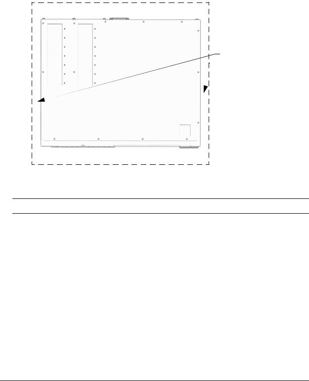
Airflow Considerations
To ensure proper airflow, be sure that your switch is placed in a well-ventilated area and provide minimum recommended clearance at the front, back and sides of the switch.
Never obstruct chassis air vents.
} Rear. 6 inches minimum at rear of chassis.
Sides. 2 inches minimum at left and right sides.
} Front. 6 inches minimum at front of chassis.
Chassis Top View
Note. Clearance is not required at the top and bottom of the chassis.
Mounting the Switch
For information on mounting OmniSwitch 6860 switches, refer to the Chapter 3, “Chassis and Power Supplies.”
page 2-4 |
OmniSwitch 6860 Hardware Users Guide September 2016 |

Getting Started |
Connections and Cabling |
|
|
|
|
Connections and Cabling
Once your switch is properly installed, you should connect all network and management cables required for your network applications. Connections may include:
•Micro USB-to-USB cable to the console connector
•Ethernet cable to the Ethernet Management Port (EMP) (Enhanced models only)
•Cables to NIs or transceivers
Note. For additional information on cabling for console, EMP, USB, Bluetooth and other connections, refer to the OmniSwitch AOS Release 8 Switch Management Guide.
Network Cable Installation Warning
Never install exposed network cables outdoors. Install network cables per manufacturer requirements.
Serial Connection to the Console Port
The console port provides a serial connection to the switch using a USB connector and is required when logging into the switch for the first time. By default, this connector provides a DCE console connection.
Serial Connection Default Settings
baud rate |
9600 |
|
|
parity |
none |
|
|
data bits (word size) |
8 |
|
|
stop bits |
1 |
For information on modifying these settings, refer to the OmniSwitch AOS Release 8 Switch Management Guide.
Ethernet Management Port (EMP) Cable Requirements
Enhanced OS6860 models (OS6860E) provide an Ethernet Management Port (EMP) on the rear panel of the chassis for out-of-band management. There are specific cable type requirements (i.e., straight-through or crossover) based on the device to which the EMP is connecting. Refer to the information below:
EMP to a Switch |
Straight-through |
|
|
EMP to a Computer or |
Crossover |
Workstation |
|
|
|
For information on manually configuring Ethernet ports, refer to the OmniSwitch AOS Release 8 Network Configuration Guide.
OmniSwitch 6860 Hardware Users Guide September 2016 |
page 2-5 |

Booting the Switch |
Getting Started |
|
|
|
|
Booting the Switch
Now that you have installed the switch components and connected network and management cables, you can boot the switch. To boot the switch, plug all power supply cords into easily-accessible, properly grounded power outlets. (Do not use extension cords.) The switch will power on and boot automatically.
Note. If you have more than one power supply installed, be sure to plug in each power supply in rapid succession, (i.e., within a few seconds of each other). This ensures that there will be adequate power for all components throughout the boot process.
Component LEDs
During the boot process, component LEDs will flash and change color, indicating different stages of the boot. Following a successful boot, chassis LEDs should display as follows:
OK1 |
Solid Green |
|
|
PRI |
Solid Green (for switches running in |
|
master role) |
|
Solid Amber (for switches running in |
|
slave role) |
|
|
PS |
Solid Green |
|
|
BPS |
Solid Green |
|
|
GRN (Power Save) |
Solid Green |
|
|
OK2 |
Solid Green |
|
|
If the LEDs do not display as indicated, make sure the boot process is complete. If the LEDs do not display as indicated following a complete boot sequence, contact Alcatel-Lucent Customer Support. For complete information on LED states, refer to “Chassis Status LEDs” on page 3-19.
Once the switch has completely booted and you have accessed your computer’s terminal emulation software via the console port, you are ready to log in to the switch’s Command Line Interface (CLI) and configure basic information. Continue to “Your First Login Session” on page 2-7.
page 2-6 |
OmniSwitch 6860 Hardware Users Guide September 2016 |

Getting Started |
Your First Login Session |
|
|
|
|
Your First Login Session
In order to complete the setup process for the switch, you must complete the following steps during your first login session:
•Log in to the switch
•Set IP address information for the Ethernet Management Port (EMP) (Enhanced models only)
•Unlock session types
•Change the login password
•Set the date and time
•Set optional system information
•Save your changes
Important. You must be connected to the switch via the console port before initiating your first login session.
Logging In to the Switch
When you first log in to the switch, you will be prompted for a login name and password. Use the switch’s default settings:
•Login: admin
•Password: switch
The default welcome banner, which includes information such as the current software version and system date, is displayed followed by the CLI command prompt:
Welcome to the Alcatel-Lucent OS6860E-P48 8.1.1, April 15, 2014.
Copyright (c) 1994-2014 Alcatel-Lucent. All Rights Reserved.
OmniSwitch(tm) is a trademark of Alcatel-Lucent, registered in the United States Patent and Trademark Office.
->
Note. A user account includes a login name, password, and user privileges. Privileges determine whether the user has read or write access to the switch and which commands the user is authorized to execute. For detailed information on setting up and modifying user accounts, refer to the OmniSwitch AOS Release 8 Switch Management Guide.
OmniSwitch 6860 Hardware Users Guide September 2016 |
page 2-7 |

Your First Login Session |
Getting Started |
|
|
|
|
Setting IP Address Information for the EMP
If installing an Enhanced OS6860 model (OS6860E), the IP address may be set via the Ethernet Management Port (EMP). To connect to the switch through the EMP Ethernet connection, use the default address below or change the port’s IP address.
Default EMP IP Address |
192.168.1.1 |
|
|
Default EMP Mask |
255.255.255.0 |
|
|
Note. You should be connected to the switch via the console port before attempting to change IP address information.
To change the default IP and mask, use the ip interface command. For example:
-> ip interface emp address 168.22.2.120 mask 255.255.255.0
Verify your settings using the show ip interface command. See the OmniSwitch AOS Release 8 Switch Management Guide for additional information regarding EMP port addressing.
Note. Although you have configured the EMP with valid IP address information, you will not be able to access the switch through this port (i.e. TELNET, FTP, HTTP, SSH or SNMP) until you have unlocked these remote session types. See “Unlocking Session Types” on page 2-9 for more information.
page 2-8 |
OmniSwitch 6860 Hardware Users Guide September 2016 |

Getting Started |
Your First Login Session |
|
|
|
|
Unlocking Session Types
Security is a key feature on OmniSwitch 6860 switches. As described on page 2-7, when you access the switch for the first time, you must use a direct console port connection. All other session types (Telnet, FTP, WebView, and SNMP) are locked out until they are manually unlocked by the user.
The CLI command used to unlock session types is aaa authentication.
Note. When you unlock session types, you are granting switch access to non-local sessions (e.g., Telnet). As a result, users who know the correct user login and password will have remote access to the switch. For more information on switch security, refer to the OmniSwitch AOS Release 8 Switch Management Guide.
Unlocking All Session Types
To unlock all session types, enter the following command syntax at the CLI prompt:
-> aaa authentication default local
Unlocking Specified Session Types
You can also unlock session types on a one-by-one basis. For example, to unlock Telnet sessions only, enter the following command:
-> aaa authentication telnet local
To unlock WebView (HTTP) sessions only, enter the following command:
-> aaa authentication http local
You cannot specify more than one session type in a single command line. However, you can still unlock multiple session types by using the aaa authentication command in succession. For example:
-> aaa authentication http local -> aaa authentication telnet local -> aaa authentication ftp local
Refer to the OmniSwitch CLI Reference Guide for complete aaa authentication command syntax options.
Changing the Login Password
Change the login password for admin user sessions by following the steps below:
1Be sure that you have logged into the switch as user type admin (see “Logging In to the Switch” on page 2-7).
2Enter the keyword password and press Enter.
3Enter your new password at the prompt.
Note. Be sure to remember or securely record all new passwords; overriding configured passwords on an OmniSwitch is restricted.
4 You will be prompted to re-enter the password. Enter the password a second time.
OmniSwitch 6860 Hardware Users Guide September 2016 |
page 2-9 |

Your First Login Session |
Getting Started |
|
|
|
|
New password settings are automatically saved in real time to the local user database; the user is not required to enter an additional command in order to save the password information. Also note that new password information is retained following a reboot. All subsequent login sessions, including those through the console port, will require the new password to access the switch.
For detailed information on managing login information, including user names and passwords, refer to the
OmniSwitch AOS Release 8 Switch Management Guide.
Setting the System Time Zone
The switch’s default time zone is UTC. If you require a time zone that is specific to your region, or if you need to enable Daylight Savings Time (DST) on the switch, you can configure these settings via the system timezone and system daylight-savings-time commands.
For detailed information on configuring a time zone for the switch, refer to the OmniSwitch AOS Release 8 Switch Management Guide.
Setting the Date and Time
Set the current time for the switch by entering system time, followed by the current time in hh:mm:ss. To set the current date for the switch, enter system date, followed by the current date in mm/dd/yyyy.
Setting Optional Parameters
Specifying an Administrative Contact
An administrative contact is the person or department in charge of the switch. If a contact is specified, users can easily find the appropriate network administrator if they have questions or comments about the switch.
To specify an administrative contact, use the system contact command.
Specifying a System Name
The system name is a simple, user-defined text description for the switch. To specify a system name, use the system name command.
Specifying the Switch’s Location
It is recommended that you use a physical labeling system for locating and identifying your switch(es). Examples include placing a sticker or placard with a unique identifier (e.g., the switch’s default IP address) on each chassis.
However, if no labeling system has been implemented or if you need to determine a switch’s location from a remote site, entering a system location can be very useful.
To specify a system location, use the system location command.
page 2-10 |
OmniSwitch 6860 Hardware Users Guide September 2016 |

Getting Started |
Your First Login Session |
|
|
|
|
Viewing Your Changes
To view your current changes, enter show system at the CLI prompt.
Saving Your Changes
Once you have configured this basic switch information, save your changes by entering write memory at the CLI command prompt.
OmniSwitch 6860 Hardware Users Guide September 2016 |
page 2-11 |
Loading...