


 Loading...
AT&T MetroCell 9962 Installation Guide
For the Alcatel-Lucent 9962 Multi-standard Enterprise Cell v1
Contents
Before you begin |
|
The AT&T MetroCell website: att.com/metrocell |
|
To install AT&T MetroCell, you will need: |
2 |
Premier username & password |
5 |
What’s in the kit |
2 |
Activating your AT&T MetroCell |
5 |
Getting to know AT&T MetroCell |
2 |
Appendix A: Local transport requirements |
|
|
|
|
|
Installation |
|
TCP/UDP Ports |
7 |
LAN configuration requirements |
3 |
IP Address Pass-Through |
7 |
Serial number |
3 |
Appendix B: Bandwidth requirements |
7 |
Site-specific hardware |
3 |
||
Placement guidelines |
3 |
Appendix C: Installing multiple MetroCells |
7 |
Environmental Requirements |
4 |
||
Device assembly |
4 |
Appendix D: Troubleshooting guide |
8 |
Step 1: Mount AT&T MetroCell |
4 |
||
Wall mount installation |
4 |
Debug interface |
8 |
Step 2: Connect AT&T MetroCell |
4 |
Steps to perform LED troubleshooting |
9 |
Power supply |
4 |
Appendix E: Radio frequency (RF) safety compliance |
11 |
PoE injector use and mounting |
4 |
||
Connect the Ethernet cables |
4 |
Appendix F: Station authorization |
11 |
GPS antenna cable connection |
5 |
||
Grounding |
5 |
Warranty |
11 |
Power Up |
5 |
||
Radio frequency (RF) safety compliance |
5 |
|
|
Station authorization |
5 |
|
|
Activation |
5 |
|
|
AT&T MetroCell 9962 installation guide • April 2016 |
1 |
Beforeyoubegin
The time required to install your AT&T MetroCell device varies with local circumstances; allow 1-2 hours for a simple installation. Once the device is installed and activation is initiated via the MetroCell website, it will take up to another 2 hours for your MetroCell to be ready for use.
For accessibility information about the AT&T MetroCell, please visit att.com/metrocell.
To install AT&T MetroCell, you will need:
1.A central location where you can attach the access point to an interior wall or column. This location should be:
-Within 100 feet of an exterior window, glass wall or door (to receive GPS signals), and preferably no closer than 15 feet to minimize propagation of the signal into areas served by the public network.
-At least 2 feet away from metal obstructions, microwave ovens, cordless phones, fans, motors, and fluorescent lighting in order to avoid interference with the radio signal.
-At least 1 foot away from any work station or place where people may gather in order to avoid excessive exposure to radio frequency emissions.
-A substantial distance from any other small cell (MetroCell, MicroCell or repeater) to avoid radio wave interference – see Appendix C when installing multiple MetroCells.
2.An available Ethernet port on a router or switch with sufficient available bandwidth to support the traffic that will be carried over the AT&T MetroCell (see Appendix B for bandwidth requirements).
3.An AT&T Premier username and password. If you do not already have a Premier admin username and password, the following document explains how to obtain these credentials: Register for Premier.
4.Some basic tools and hardware (drill, hammer, screw driver, screws, wall anchors, cable fasteners).
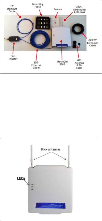
What’s in the kit
Examine the contents of the MetroCell kit. If you notice any damage, please notify the carrier who delivered the unit and contact your AT&T representative.
The MetroCell 9962 kit contains the following components:
• Box 1: AT&T MetroCell 9962, mounting plate, GPS antenna, package of screws
• Box 2/5: Two omni-directional (“stick”) antennas, power supply (not used in typical installations)
•Box 3: Power over Ethernet 4p (PoE) injector
•Box 4/6/7: 10’ Ethernet cable, 150’ Ethernet cable
(shielded Cat5e), and 70’ GPS antenna extension
Box 1 is the largest, followed in size by Box 4/6/7, Box 3, and Box 2/5. Note: packaging may not be exactly as described.
Note that the typical installation described in these instructions may not require several components in the kit, including the 48V AC/DC power adaptor and power cord.
Getting to know AT&T MetroCell
The AT&T MetroCell is an Alcatel-Lucent 9962 Multistandard Enterprise Cell v1, or “9962”.
Several features you should be aware of:
•Two “stick” antennas screw into the top edge of the MetroCell near the sides.
•There are 4 LED lights on the left side of the front cover.
AT&T MetroCell 9962 installation guide • April 2016 |
2 |
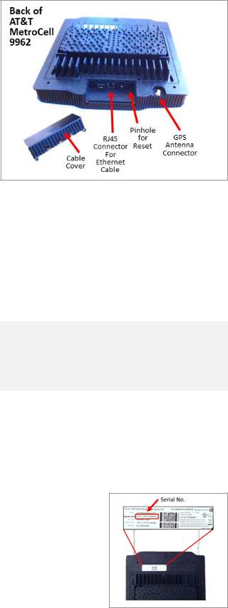
•A small section of the bottom of the back cover slides off to reveal various cable connection points. A similar section at the top of the back cover slides off to reveal 7 antenna connection terminals. The latter are not used in standard installations. Each cover section is secured by 2 recessed phillips-head screws, which must be removed to open them.
Installation
LAN configuration requirements
To activate an AT&T MetroCell, it must be able to communicate with a dynamic Internet address in the AT&T Mobility network. If you’re connecting the MetroCell to a customer-provided router that has a simple configuration and hasn’t been customized, it likely won’t be necessary to make any changes to the router settings.
•If the router configuration has been customized or you are using a firewall, please consult the Local transport requirements in Appendix A, as well as
documentation from the router manufacturer and/or Internet Service Provider.
Make sure that there is an available Ethernet port on a router or Ethernet switch with sufficient available
bandwidth to support the traffic that will be carried over the MetroCell. See Appendix B for bandwidth requirements.
Serial number
Record the 18-character serial number before mounting the MetroCell. You will need this identifier during activation. It can be found on the
label on the back of the 9962 (“Serial No.
3G/4G”) and also on the shipping label.
Site-specific hardware
All site-specific installation materials such as screws and wall anchors are the responsibility of the party performing the installation and are not included in the MetroCell kit.
Placement guidelines
The AT&T MetroCell is for indoor use only.
The following are guidelines for placement of the MetroCell:
•Install the MetroCell in a central location, relative to the desired coverage area.
•The MetroCell should be installed on an interior wall or column near the ceiling.
•Do not install the MetroCell close to metal obstructions such as heating and air-conditioning ducts, large roof or ceiling trusses, or major power cables.
•Walls between the MetroCell and users will reduce signal strength. Solid metal or metal mesh can block a radio signal entirely. Signals can typically penetrate one or two solid concrete walls, three or four cinder block walls, five or six drywall or wood walls.
•Avoid installing the MetroCell within a few feet of microwave ovens, cordless phones, fans, motors, and fluorescent lighting.
•The MetroCell should not be mounted where any person will spend more than a minute within a 12-inch radius of the device when it is active. See Appendix E for additional details.
•Locate the device in a spot which will permit the GPS Antenna, with its 30 ft. cord and 70 ft. extension, to reach an exterior window, glass wall or door to receive GPS signals. If the device is unable to receive a GPS signal,
it will not be able to complete activation. If multiple MetroCells (maximum of 3) are to be installed at the same address and are provisioned in a single “Group”, only one of them needs to have its GPS antenna reach a window, depending on placement and building construction.
•The MetroCell kit includes 150 ft. of shielded Cat5e Ethernet cable. Select a location for the MetroCell that is within 150 ft. of the router or switch port to which it will be connected. If necessary, the MetroCell can be as far away as 300 feet from the router or switch. If a cable longer than 150 feet is required, the customer or installer must provide this cable, which must be shielded Cat 5e with metallic “boots”. In the case of installations performed by AT&T, AT&T will provide the longer cable.
•The MetroCell being installed should be 50 to 100 feet away from any other MetroCell, MicroCell, or repeater. See Appendix C for additional information on installing multiple MetroCells.
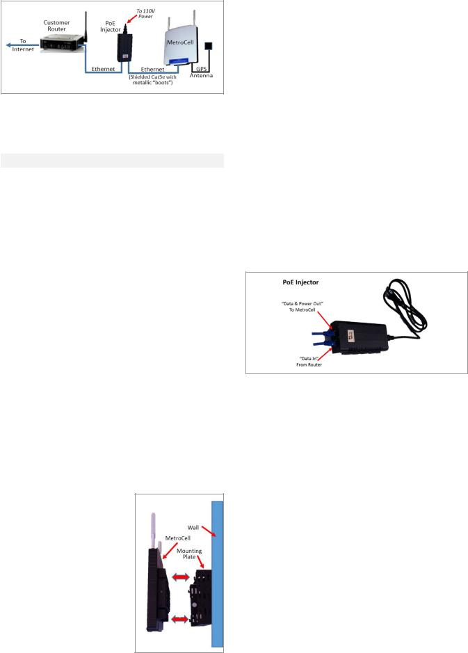
Connectivity between the key components is as follows:
•A customer-provided router or switch is connected to the Internet.
•The router/switch is connected by a short Ethernet cable to a PoE injector, which is also connected to 110V AC power and an electrical ground.
•The PoE injector is connected over Cat5e shielded Ethernet cable to the MetroCell.
AT&T MetroCell 9962 installation guide • April 2016 |
3 |
Environmental Requirements
The following are the environmental requirements for the MetroCell device:
Parameter |
Value |
|
|
Temperature range |
0°C to 50°C |
|
[32°F to 122°F] |
|
|
Relative humidity |
Up to 93% |
|
|
The MetroCell and all its components (including cables and power adaptor) must be placed in a dry area and kept away from any wet or damp environments such as lavatories or any other areas with exposure to moisture, sprays, drips, or running water.
Device assembly
Unpack the MetroCell.
Find the 2 “stick” antennas, each about 8 inches long, and screw them into the connection points on the top edge of the MetroCell.
Step 1: Mount AT&T MetroCell
Wall mount installation
The 9962 requires a mounting plate to be installed on the wall. It is mounted with the large side against the wall and the hooks on the sides away from the wall and pointing up.
Note: The wall mount implies that the MetroCell is vertically installed with the stick antennas pointing upwards (not downwards or sideways). The stick antennas cannot be bent. Failure to comply with these requirements may change and degrade the performance of the MetroCell.
To mount the device onto a wall or column, perform the following steps.
1.Select a location where the MetroCell can be mounted in a vertical position.
2.Hold the mounting plate against the wall where it is to be installed and mark the positions for 4 holes to be drilled near the corners.
3.For each marking, drill a hole in the wall with the appropriately sized drill bit. Insert an anchor into each drilled hole. Use an anchor that is appropriate for the wall material. These must be provided by the installer.
4.Attach the mounting plate to the wall using appropriate screws.
5.Line up the 4 slots in the back of the MetroCell with the 4 hooks protruding from the mounting plate.
6.There are screw holes in the sides of the mounting plate which align with holes in the sides of the MetroCell. Insert the 4 screws (provided in the wall mounting kit) to attach the 9962 to the mounting plate.
7.The mounting plate also has a hole in the side which can be used to insert a lock (not provided).
Step 2: Connect AT&T MetroCell
Power supply
The MetroCell must be powered by either the provided Power over Ethernet (4p PoE) injector or by the provided 48V AC/DC power adaptor. Do NOT use both at the same time, and do NOT use Power over Ethernet from a router or switch. In most cases, the PoE injector is recommended since it requires that only one cable be run to the MetroCell.
If the PoE Injector is used, the cable connecting the PoE injector and the MetroCell must be shielded Cat5e, and the connectors at both ends must have metallic “boots”.
PoE injector use and mounting
1.PoE Injectors should be mounted in data equipment locations and must not be mounted above the ceiling or near the MetroCell.
2.The PoE Injector should be secured to an equipment rack, if the customer has one available, or to another secure fixture.
Connect the Ethernet cables
To attach the Ethernet cables, perform the following steps.
1.Route the supplied 10 foot Ethernet cable from the router or switch to the PoE Injector and plug it into the Data In jack in the injector.
2.Remove 2 recessed screws securing the small section of the bottom back cover of the MetroCell and remove it to reveal the Ethernet and GPS connectors.
3.Plug one end of the 150 foot Ethernet cable into the RJ45 Ethernet jack on the back of the MetroCell. Put the cable cover back on.
AT&T MetroCell 9962 installation guide • April 2016 |
4 |
Loading...