


Edition |
Modification |
Date |
01 |
Documentation creation by association of the BE1 and BE3 technical documentation in one |
09/03/2000 |
|
documentation |
|
02 |
Audio modification on BE3 |
06/06/2000 |
03 |
Documentation correction on page 19 |
13/06/2000 |
04 |
Flow chart and visual inspection modification ;Battery test ; new fault codes and a mandatory |
05/10/2000 |
|
equipment list; Audio modification for BE1 and BE3 |
|
|
|
|
|
|
|
|
|
|
|
|
|
|
|
|
Explanation of the modifications since the last edition
Improvement |
Correction |
Comments |
Audio improvements on BE1 and |
Replace the audio amplifier by an Analog |
|
BE3 products |
Device amplifier if the solder modification |
|
|
does not solve the problem |
|
Battery test |
|
|
|
|
|
|
Author |
Approbation 1 |
Approbation 2 |
FUNCTION: |
Pilot Repair Centre |
Pilot Repair Centre |
Technical Assistance |
DATE: |
|
|
|
VISA: |
|
|
|
|
|
|
|
ED |
04 |
09/10/00 REPAIR DOCUMENTATION BE1 and BE3 Level 2 |
BE 1/BE3 |
|
|
|
|
|
|
|
1/46 |
|
|
|
|
All rights reserved.Passing on and copying of this document, use and communication of its contents are not permitted without authorization

CONTENTS
1) LEVEL 2 REPAIR PROCESS |
3 |
2) TEST & VISUAL INSPECTION |
4 |
3) DISASSEMBLY OF THE PRODUCT |
8 |
4) HARDWARE UPGRADING |
20 |
5) REPAIR |
24 |
6) ASSEMBLY OF THE PRODUCT |
27 |
7) STICKERS |
39 |
8) CUSTOMIZATION SOFTWARE DOWNLOADING |
41 |
9) FINAL TEST |
42 |
9.1 Functionnal test |
42 |
9.2 Measurements |
42 |
APPENDIX 1 FAULT CODES |
43 |
APPENDIX 2 EQUIPMENT FOR LEVEL 2 REPAIR CENTRE |
45 |
ED |
04 |
11/10/00 REPAIR DOCUMENTATION BE1 and BE3 Level 2 |
BE 1/BE3 |
|
|
|
|
|
|
|
2/46 |
|
|
|
|
All rights reserved.Passing on and copying of this document, use and communication of its contents are not permitted without authorization
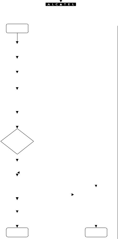
1) LEVEL 2 REPAIR PROCESS
start
|
Test + visual inspection |
|
|
|
|
|
|
|
See § 2 |
||||||
|
|
|
|
|
|
|
|
|
|
|
|
|
|
||
|
|
|
|
|
|
|
|
|
|
|
|
|
|
||
|
|
|
|
|
|
|
|
|
|
|
|
|
|
|
|
|
|
Disassembly |
|
|
|
|
|
|
|
See § 3 |
|||||
|
|
|
|
|
|
|
|
|
|
|
|
|
See § 4 |
||
|
|
|
|
|
|
|
|
|
|
|
|
|
|||
|
|
|
|
|
|
|
|
|
|
|
|
|
|
|
|
|
|
Hardware upgrading |
|
|
|
|
|
|
|
||||||
|
|
|
|
|
|
|
|
|
|
|
|
|
See § 5 |
||
|
|
|
|
|
|
|
|
|
|
|
|
|
|||
|
|
|
|
|
|
|
|
|
|
|
|
||||
|
|
Level 2 repair |
|
|
|
|
|
|
|
||||||
|
|
|
|
|
|
|
|
|
|
|
|
|
|
||
|
|
|
|
|
|
|
|
|
|
|
|
|
|
|
|
|
|
|
|
|
|
|
|
|
|
|
|
|
|
|
|
|
|
Final assembly |
|
|
|
|
|
|
|
See § 6 |
|||||
|
|
|
|
|
|
|
|
|
|
|
|
|
|
||
|
|
|
|
|
|
N0 |
|
|
|
|
|
|
|
||
|
|
Rear casing is |
|
|
|
|
|
|
|
|
|||||
|
|
|
changed ? |
|
|
|
|
|
|
|
|
||||
|
|
|
|
|
|
YES |
|
|
|
|
|
|
|
|
|
|
|
|
|
|
|
|
|
|
|
|
|
|
|
||
|
|
|
|
|
|
|
|
|
|
|
|
|
|
|
|
|
Complete sticker printing |
|
|
|
|
|
|
|
See § 7 |
||||||
|
|
|
|
|
|
|
|
|
|
|
|
|
|
|
See § 8 |
|
|
|
|
|
|
|
|
|
|
|
|
|
|
|
|
|
|
|
|
|
|
|
|
|
|
|
|
|
|
|
|
|
Customization software downloading |
|
|
|
|
|
|
||||||||
|
NOK |
|
|||||||||||||
|
|
|
|||||||||||||
|
|
|
|
|
|
|
|
|
|
|
|||||
|
|
|
|
|
|
|
|
|
|
|
|
|
|
|
|
|
|
|
|
|
|
|
|
|
|
|
|
|
|
|
|
|
|
|
|
|
|
OK |
|
|
|
|
|
To a Level 3 repair centre |
|
||
|
|
|
|
|
|
|
|
|
|
|
See § 7 |
||||
|
|
|
|
|
|
|
|
|
|
|
|
|
|
|
|
|
|
|
|
|
|
|
|
|
|
|
|
|
|
|
|
|
|
|
|
|
|
|
|
|
|
||||||
|
Software technical level sticker |
|
|
|
|
|
|
||||||||
|
|
|
|
|
|
|
|
|
|
|
|
|
|
|
See § 9 |
|
|
|
|
|
|
|
|
|
|
|
|
|
|
|
|
|
|
|
|
|
|
|
|
|
|
|
|
|
|
|
|
|
|
|
Final test |
|
|
|
|
|
|
|
|||||
|
|
|
|
NOK |
|
||||||||||
|
|
|
|
|
|
||||||||||
|
|
|
|
|
|
|
|
|
|
|
|||||
|
|
|
|
|
|
|
|
|
|
|
|
|
|
|
|
|
|
|
|
|
|
OK |
|
|
|
|
|
|
|
|
|
|
|
|
|
|
|
|
|
|
|
|
|
|
|||
|
|
|
end |
|
|
|
|
|
end |
|
|||||
|
|
|
|
|
|
|
|
|
|
|
|
|
|
||
ED |
|
04 |
|
|
09/10/00 REPAIR DOCUMENTATION BE1 and BE3 Level 2 |
BE 1/BE3 |
|||||||||
|
|
|
|
|
|
|
|
|
|
|
|
|
|
|
|
|
|
|
|
|
|
|
|
|
|
|
|
|
|
|
3/46 |
|
|
|
|
|
|
|
|
|
|
|
|
|
|
|
|
All rights reserved.Passing on and copying of this document, use and communication of its contents are not permitted without authorization
2) TEST & VISUAL INSPECTION
ALL these verifications must be done on ALL products coming back in a LEVEL 2 after sales repair centre .
a)Check the aspect of the rear casing and the antenna
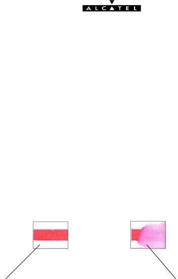
b)Humidity sticker : a humidity sticker is present on some BE1 terminals on the shielding that can be seen on the rear casing side, without openning the handset . Check the state of the sticker as shown below :
Sticker of a good terminal |
Sticker of a terminal dived in water |
|
This terminal is out of the warranty |
c)Check J904 , the charge connector (corrosion ,contacts)
d)Check the SIM latch right functioning
e)Insert a SIM card and check the holding of the SIM latch
f)Plug a good battery and switch on the handset : check the charging icon animation on the display, check the holding of the product on the desk top charger.
ED |
04 |
09/10/00 REPAIR DOCUMENTATION BE1 and BE3 Level 2 |
BE 1/BE3 |
|
|
|
|
|
|
|
4/46 |
|
|
|
|
All rights reserved.Passing on and copying of this document, use and communication of its contents are not permitted without authorization
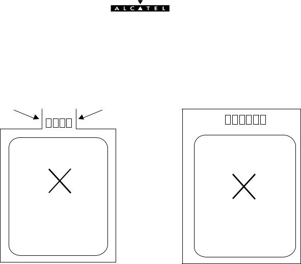
g) When the handset with its battery comes back to be repaired, you must measure the voltage and the Thermistor value as shown below.
1 |
|
|
|
|
|
6 |
|
|
|
|
|
|
|
|
|
|
|
2 |
3 |
4 |
5 |
|
|
|
|
|
|
|
|
|
|||||
|
|
|
|
|
|
|
|
|
|
|
|
|
|||||
|
|
|
|
|
|
|
|
|
|
|
|
|
|||||
|
|
|
|
|
|
|
|
|
|
|
|
|
|
|
|
|
|
1 2 3 4 5 6
ASSEMBLEDINFRANCE
ASSEMBLEDINFRANCE
POWERPACK |
POWERPACK |
ALCATEL |
|
|
ALCATEL |
NI MH Battery |
Lithium battery |
With a multimeter:
∙Measure the voltage between pin 1 and pin 6 (if < 2.9 V, the battery is NOK)
∙Measure the Thermistor value between pin 5 and pin 6 for Ni MH battery
∙Measure the Thermistor value between pin 4 and pin 6 for Lithium battery (the Thermistor value must be 100 k? at 25 °C)
ED |
04 |
09/10/00 REPAIR DOCUMENTATION BE1 and BE3 Level 2 |
BE 1/BE3 |
|
|
|
|
|
|
|
5/46 |
|
|
|
|
All rights reserved.Passing on and copying of this document, use and communication of its contents are not permitted without authorization
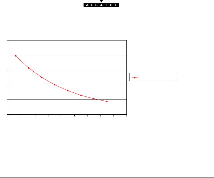
Resistor value/ temperature
250 |
|
|
|
|
|
|
|
200 |
|
|
|
|
|
|
|
150 |
|
|
|
|
|
|
|
|
|
|
|
|
|
|
Thermistor kO |
100 |
|
|
|
|
|
|
|
50 |
|
|
|
|
|
|
|
0 |
|
|
|
|
|
|
|
10 |
15 |
20 |
25 |
30 |
35 |
40 |
45 |
Temperature (°C)
If these measurements are NOK, the battery is swapped and returned to Pilot Repair Centre of Laval.
If these measurements are OK : plug the battery on a good handset, put it on a charger and check the charge icon animation.
ED |
04 |
09/10/00 REPAIR DOCUMENTATION BE1 and BE3 Level 2 |
BE 1/BE3 |
|
|
|
|
|
|
|
6/46 |
|
|
|
|
All rights reserved.Passing on and copying of this document, use and communication of its contents are not permitted without authorization

h)Switch on the handset and check the right functioning of the keyboard and the volume keys ; check the display backlighting
i)Switch off the product
j)Test the date and hour function
Plug a dummy battery (ref : SAVBE10004) on a 3,8v power supply , switch on the handset , adjust the date and hour , switch off the product and wait for 10 seconds .
Switch on the handset again , if the product asks for the date and hour , the handset must be sent to a LEVEL 3 repair centre.
ED |
04 |
09/10/00 REPAIR DOCUMENTATION BE1 and BE3 Level 2 |
BE 1/BE3 |
|
|
|
|
|
|
|
7/46 |
|
|
|
|
All rights reserved.Passing on and copying of this document, use and communication of its contents are not permitted without authorization
All rights reserved. Passing on and copying of this |
document, use and communication of its contents |
not permitted without written authorization. |
ED |
D00 05/10/2000 |
REPAIR DOCUMENTATION L |
MULTI-PRODUIT |
|
BE1/BE3 |
||||
|
|
|
Dir:/data/RAFT/DATA_ALCATEL/doc/ |
00000 |
Ref: |
8 / 46 |
All rights reserved. Passing on and copying of this |
document, use and communication of its contents |
not permitted without written authorization. |
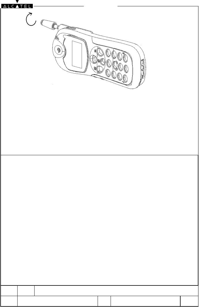
No specific tool is required to remove the antenna ,just hand-unscrew it .
ED |
D00 05/10/2000 |
REPAIR DOCUMENTATION L |
MULTI-PRODUIT |
|
BE1/BE3 |
||||
|
|
|
Dir:/data/RAFT/DATA_ALCATEL/doc/ |
00000 |
Ref: |
9 / 46 |
All rights reserved. Passing on and copying of this |
document, use and communication of its contents |
not permitted without written authorization. |
Use pliers to remove the J 300( antenna switch) protection
ED |
D00 05/10/2000 |
REPAIR DOCUMENTATION L |
MULTI-PRODUIT |
|
BE1/BE3 |
||||
|
|
|
Dir:/data/RAFT/DATA_ALCATEL/doc/ |
00000 |
Ref: |
10 / 46 |
All rights reserved. Passing on and copying of this |
document, use and communication of its contents |
not permitted without written authorization. |
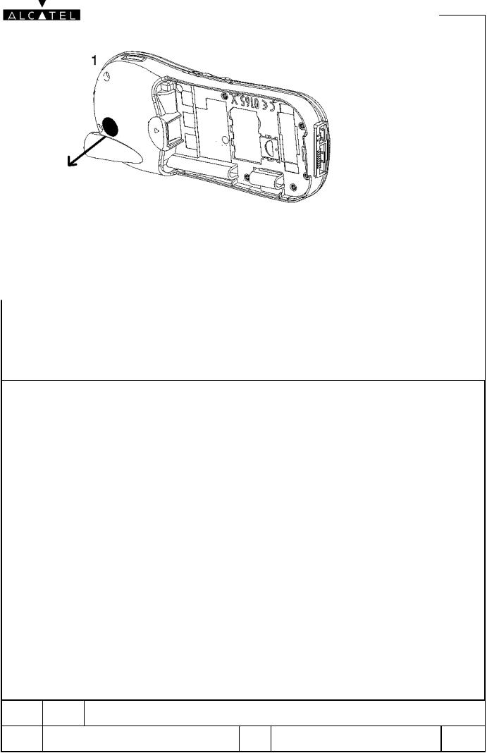
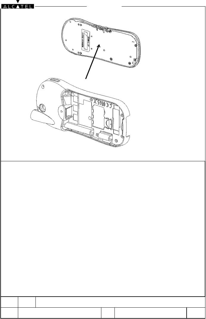
Place the product on the plastic positionning tool(positon 2) . Remove the 2 black screws .
ED |
D00 05/10/2000 |
REPAIR DOCUMENTATION L |
MULTI-PRODUIT |
|
BE1/BE3 |
||||
|
|
|
Dir:/data/RAFT/DATA_ALCATEL/doc/ |
00000 |
Ref: |
11 / 46 |
All rights reserved. Passing on and copying of this |
document, use and communication of its contents |
not permitted without written authorization. |
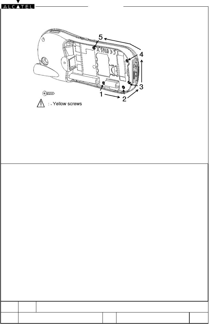
Remove the 5 yellow screws
ED |
D00 05/10/2000 |
REPAIR DOCUMENTATION L |
MULTI-PRODUIT |
|
BE1/BE3 |
||||
|
|
|
Dir:/data/RAFT/DATA_ALCATEL/doc/ |
00000 |
Ref: |
12 / 46 |
All rights reserved. Passing on and copying of this |
document, use and communication of its contents |
not permitted without written authorization. |
Disassemble the front casing and the MMI board from the other part of the product
(shielding, radiodigital board and rear casing)
ED |
D00 05/10/2000 |
REPAIR DOCUMENTATION L |
MULTI-PRODUIT |
|
BE1/BE3 |
||||
|
|
|
Dir:/data/RAFT/DATA_ALCATEL/doc/ |
00000 |
Ref: |
13 / 46 |

All rights reserved. Passing on and copying of this |
document, use and communication of its contents |
not permitted without written authorization. |
Remove the 3 grey screws
ED |
D00 05/10/2000 |
REPAIR DOCUMENTATION L |
MULTI-PRODUIT |
|
BE1/BE3 |
||||
|
|
|
Dir:/data/RAFT/DATA_ALCATEL/doc/ |
00000 |
Ref: |
14 / 46 |
 Loading...