


AEG S75400KG, S75408KG, S75390KG3, S75388KG6, S75398KG3 Service Manual
...SERVICE MANUAL
REFRIGERATION
©Electrolux Home Products S.p.A. Spares Operations Italy
Corso lino Zanussi, 30 I - 33080 Porcia (PN) Fax +39 0434 394096
S.O.I.
Edition: 11.2006
|
REFRIGERATORS |
|
|
NO FROST |
|
Publication no. |
TOTAL |
|
599 38 47-44 |
with |
|
ERF2050 |
||
|
||
EN |
electronic |
|
|
DIGITS |
|
|
AEG styling |
|
|
FACTORY: HUY |
|
|
|
- ITZAA |
1/44 |
599 38 47-44 |
CONTENT
1 |
INTRODUCTION ....................................................................................................................................... |
5 |
|
2 |
AIR CIRCULATION.................................................................................................................................... |
7 |
|
3 |
REFRIGERATION CIRCUIT...................................................................................................................... |
8 |
|
4 |
ELECTRIC WIRING................................................................................................................................... |
9 |
|
5 |
COMPONENTS ....................................................................................................................................... |
11 |
|
|
5.1 |
Control panel ................................................................................................................................... |
11 |
|
5.2 |
Electronic boards ............................................................................................................................. |
12 |
|
|
5.2.1 Power board ERF2050 ........................................................................................................... |
13 |
|
|
5.2.2 Display board ERF2000.......................................................................................................... |
16 |
|
5.3 |
Cooler compartment ........................................................................................................................ |
17 |
|
|
5.3.1 Temperature sensor ............................................................................................................... |
18 |
|
|
5.3.2 Door switch ............................................................................................................................. |
18 |
|
|
5.3.3 Air flow regulator (damper) ..................................................................................................... |
19 |
|
|
5.3.4 Carbon air filter ....................................................................................................................... |
19 |
|
|
5.3.5 LED lighting (optional depending on the models) ................................................................... |
20 |
|
5.4 |
Freezer compartment ...................................................................................................................... |
21 |
|
|
5.4.1 Cold module............................................................................................................................ |
22 |
|
|
5.4.2 Thermal switches.................................................................................................................... |
22 |
|
|
5.4.3 Cold module fan...................................................................................................................... |
23 |
|
|
5.4.4 Defrosting heater .................................................................................................................... |
23 |
|
|
5.4.5 Temperature sensor ............................................................................................................... |
24 |
|
|
5.4.6 Door switch ............................................................................................................................. |
25 |
|
5.5 |
Compressor compartment ............................................................................................................... |
25 |
6 |
MAIN FUNCTIONS .................................................................................................................................. |
26 |
|
|
6.1 |
Normal ............................................................................................................................................. |
26 |
|
6.2 |
Normal with first switching on or power failure ................................................................................ |
27 |
|
6.3 |
Defrosting ........................................................................................................................................ |
28 |
|
6.4 |
Flow chart for the defrosting management ...................................................................................... |
29 |
|
6.5 |
FROSTMATIC Function (rapid freezing) ......................................................................................... |
30 |
|
6.6 |
COOLMATIC Function (rapid cooling)............................................................................................. |
30 |
|
6.7 |
HOLIDAY Function (valid only for the cooler).................................................................................. |
30 |
|
6.8 |
Malfunctioning of cooler air temperature sensor.............................................................................. |
31 |
|
6.9 |
Malfunctioning of freezer temperature sensor ................................................................................. |
32 |
7 |
ALARMS .................................................................................................................................................. |
33 |
|
|
7.1 |
Freezer compartment temperature alarm ........................................................................................ |
33 |
8 |
ACCESSIBILITY ...................................................................................................................................... |
34 |
|
|
8.1 |
Freezer compartment ...................................................................................................................... |
34 |
|
|
8.1.1 Battery evaporator .................................................................................................................. |
34 |
|
8.2 |
Control panel ................................................................................................................................... |
38 |
|
8.3 |
Cooler compartment accessibility .................................................................................................... |
40 |
|
|
8.3.1 Air flow regulator (damper) ..................................................................................................... |
40 |
|
|
8.3.2 LED lighting (optional depending on the models) ................................................................... |
41 |
9 |
TROUBLESHOOTING............................................................................................................................. |
42 |
|
|
9.1 |
Excessive ice formation on the battery : .......................................................................................... |
42 |
|
9.2 |
Failed defrosting: ............................................................................................................................. |
42 |
- ITZAA |
2/44 |
599 38 47-44 |
10 DISPLAY SYMBOLS ............................................................................................................................... |
43 |
|
10.1 |
Cooler compartment ....................................................................................................................... |
43 |
10.2 |
Freezer compartment ..................................................................................................................... |
44 |
- ITZAA |
3/44 |
599 38 47-44 |
- ITZAA |
4/44 |
599 38 47-44 |
1 INTRODUCTION
This manual describes the TOTAL NO FROST refrigerators with ERF2050 DIGITS electronic AEG styling produced in the Nyíregyháza factory (HUY).
These models feature:
-Total No Frost (no frost freezer, refrigerator no frost)
-free standing
-single-compressor
-electronic control (electronic board ERF2021)
-digit display AEG styling
-air flow regulator (damper)
-LED lighting (optional depending on the model)
They are appliances (CBNF 350, CBNF 390 e CBNF 395) with the following PNCs:
PNC |
MODEL |
BRAND |
|
|
|
925034004 |
S75358KG3 |
AEG-Electrolux |
|
|
|
925034005 |
S75358KG3 |
AEG-Electrolux |
|
|
|
925034006 |
S75350KG3 |
AEG-Electrolux |
|
|
|
925034007 |
S75358KG3 |
AEG-Electrolux |
|
|
|
925034026 |
S75340KG6 |
AEG-Electrolux |
|
|
|
925034027 |
S75348KG6 |
AEG-Electrolux |
|
|
|
925034030 |
S75348KG6 |
AEG-Electrolux |
|
|
|
925034203 |
S75398KG3 |
AEG-Electrolux |
|
|
|
925034204 |
S75398KG3 |
AEG-Electrolux |
|
|
|
925034205 |
S75390KG3 |
AEG-Electrolux |
|
|
|
925034206 |
S75398KG3 |
AEG-Electrolux |
|
|
|
925034226 |
S75388KG6 |
AEG-Electrolux |
|
|
|
925034228 |
S75388KG6 |
AEG-Electrolux |
|
|
|
925034402 |
S75408KG |
AEG-Electrolux |
|
|
|
925034403 |
S75400KG |
AEG-Electrolux |
|
|
|
The controls of the appliance are inserted into the work top. The power control board is ERF2050.
The user interface board is ERF2000 (DIGIT display) with AEG styling.
Since it is a single-compressor, it is not possible to switch off only one of the two compartments. The temperatures regulation is the following:
•from +8 to +2 °C for the cooler
•from -15 to -24 °C for the freezer
The DIGIT display enables to show the temperatures of the two compartments.
- ITZAA |
5/44 |
599 38 47-44 |
The appliance has the following functions:
•rapid freezing
•rapid cooling
•freezer temperature alarm
•cooler compartment holiday
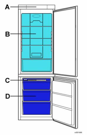
The appliance consists of the following compartments:
•freezer;
•cooler;
The evaporating circuit consists of:
•cold module (freezer compartment);
Key:
A = control panel
B = cooler compartment (No Frost)
C = cold module
D = freezer compartment (No Frost)
- ITZAA |
6/44 |
599 38 47-44 |
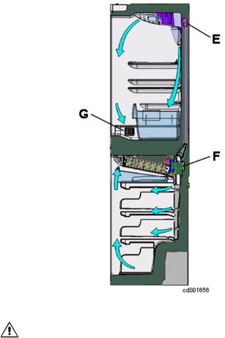
2 AIR CIRCULATION
Unlike in the PARTIAL NO FROST refrigerator, in the TOTAL type the cooler and the freezer communicate each other, therefore, the battery evaporator cools both compartments.
The cold produced by the battery evaporator in the freezer compartment, is distributed by the fan F placed behind the cold module.
Cooler compartment air flow: the cold air is pushed by the fan into the foamed duct and exits from the air flow regulator (damper) E located in the rear part of the diffuser-lamp holder.
The air returns in the freezer compartment by means of some foamed ducts entering the air vent grids G.
Freezer compartment air flow: the cold air is pushed into the compartment through the air screen and returns into the cold module through the front air vent grid.
In case of opening of the freezer or cooler door the fan stops.
To simulate the door closed use a magnet and put it next to the reed element located in the electronic board or push the freezer door button.
- ITZAA |
7/44 |
599 38 47-44 |
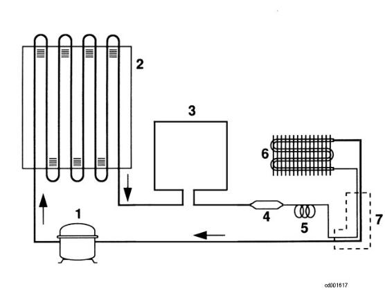
3 REFRIGERATION CIRCUIT
Key:
1.compressor;
2.condenser;
3.anti-condensation coil;
4.dehydrator filter;
5.capillary;
6.battery evaporator (freezer compartment);
7.exchanger.
- ITZAA |
8/44 |
599 38 47-44 |

4 ELECTRIC WIRING
(Check the specific diagram for each model!)
- ITZAA |
9/44 |
599 38 47-44 |
Key:
1.connection box
3.compressor
5.motor protector
9.defrosting heater
13.lamp
16.freezer door switch
19.ON/OFF switch
24.fan
26.safety thermal switch (+40 °C)
27.defrosting cut-out switch (+8 °C)
41.electronic board ERF 2050
52.air flow regulator (damper)
56.cooler air temperature sensor (cable colour: brown)
57.freezer air temperature sensor (cable colour: white)
67.LED electronic board (optional)
a.yellow-green
b.brown
c.blue
d.white
e.black
- ITZAA |
10/44 |
599 38 47-44 |
5 COMPONENTS
5.1 Control panel
Key:
Cooler compartment
A.ON/OFF button
B.cooler temperature increase button (+)
C.cooler temperature displaying
D.cooler temperature decrease button (-)
E.COOLMATIC function button (rapid cooling)
F.COOLMATIC function pilot lamp (rapid cooling) Freezer compartment
G.FROSTMATIC function pilot lamp (rapid freezing)
H.FROSTMATIC function button (rapid freezing)
I.freezer temperature increase button (+)
J.freezer temperature displaying
K.freezer temperature decrease button (-)
L.alarm deactivation button
M.alarm pilot lamp
- ITZAA |
11/44 |
599 38 47-44 |
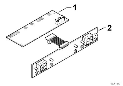
5.2 Electronic boards
The electronic board of the appliance consists of:
1.power board ERF2050
2.display board ERF2000
The two electronic boards are connected by means of a flat cable with a connector; therefore, the two boards are available singularly as spare part.
- ITZAA |
12/44 |
599 38 47-44 |
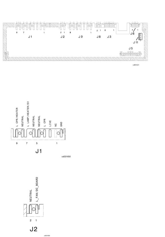
5.2.1 Power board ERF2050
- View of the electronic board (side of components):
1. earth contact
2. free
3. line
4. compressor
5. neutral
6. lamp neutral
7. lamp
8. defrosting heater neutral
9. defrosting heater
1. fan line
2. fan neutral
- ITZAA |
13/44 |
599 38 47-44 |
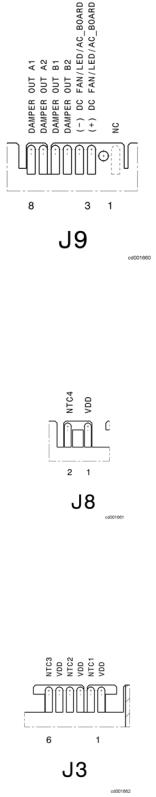
1.free
2.free
3.LED light board (+) (optional)
4.LED light board (-) (optional)
5.damper
6.damper
7.damper
8.damper
1.free
2.free
1.cooler air temperature sensor
2.cooler air temperature sensor
3.free
4.free
5.freezer air temperature sensor
6.freezer air temperature sensor
- ITZAA |
14/44 |
599 38 47-44 |
 Loading...