


Gebrauchsanweisung,Noticed'utilisationetd'installation,Installatie-engebruiksaanwijzing
EFC 1460
EFC 1420
User manual, Istruzioni per l'uso, Instrucciones de montaje y manejo, Manual de Instruções
EFC 1420
EFC 1460
D F NL UK I E P

Contents
UK
Safety warnings .................................................................................................................................................. |
42 |
For the installer ..................................................................................................................................................... |
42 |
For the user ........................................................................................................................................................... |
42 |
Description of the Appliance .......................................................................................................................... |
43 |
Extractor version ................................................................................................................................................... |
43 |
Filter Version ......................................................................................................................................................... |
43 |
Control Panel - EFC 1460 ............................................................................................................................... |
43 |
Control Panel - EFC 1420 ............................................................................................................................... |
44 |
Maintenance and care ...................................................................................................................................... |
45 |
Cleaning the hood ................................................................................................................................................. |
45 |
Metal grease filter ................................................................................................................................................. |
45 |
Removing the metal grease filter .......................................................................................................................... |
45 |
Charcoal filter ....................................................................................................................................................... |
46 |
Changing the light bulb .......................................................................................................................................... |
46 |
What to do if ...................................................................................................................................................... |
47 |
Special accessories* ......................................................................................................................................... |
47 |
Technical assistance service ........................................................................................................................... |
48 |
Service and spare parts for UK ...................................................................................................................... |
48 |
Technical Specifications ................................................................................................................................... |
48 |
Installation ......................................................................................................................................................... |
49 |
Unpacking ............................................................................................................................................................. |
49 |
Placement ............................................................................................................................................................. |
49 |
Electrical connection ............................................................................................................................................. |
49 |
Mounting accessories included ............................................................................................................................. |
50 |
Preliminary information for installing the hood ...................................................................................................... |
50 |
Mounting ............................................................................................................................................................... |
51 |
Before you use the cooker hood we recommend that you read through the whole user manual giving a direct description of the cooker hood and its functions.
To avoid the risks, that are always present when you use a product driven by electricity, it is important that the cooker hood is installed correctly and that you read the safety instructions carefully to avoid misuse and hazard. Save the instruction manual and keep it available at use of the cooker hood
41

Safety warnings
For the installer
•When used as an extractor unit, the hood must be fitted with a 150mm diameter hose.
Only for model EFC 1460 X / 942 120 706:
Should there already be a pipe of diameter 125 mm that ducts to the outside through the walls or roof, it is possible to use the 150/125 mm reduction flange provided. In this case the hood will be slightly noisier.
•When installing the hood, make sure you
respect the following minimum distance from the top edge of the cooking hob/ring
surfaces: |
|
electric cookers |
500 mm |
gas cookers |
650 mm |
coal and oil cookers |
700 mm min. |
•The national Standard on fuel-burning systems specifies a maximum depression of 0.04 mbar in such rooms.
•The air outlet must not be connected to chimney flues or combustion gas ducts. The air outlet must under no circumstances be connected to ventilation ducts for rooms in which fuel-burning appliances are installed.
•The air outlet installation must comply with the regulations laid down by the relevant authorities.
•When the unit is used in its extractor version, a sufficiently large ventilation hole must be provided, with dimensions that are approximately the same as the outlet hole.
•National and regional building regulations impose a number of restrictions on using hoods and fuel-burning appliances connected to a chimney, such as coal or oil room-heaters and gas fires, in the same room.
•Hoods can only be used safely with appliances connected to a chimney if the room and/or flat (air/environment combination) is ventilated from outside using a suitable ventilation hole approximately 500-600 cm2 large to avoid the possibility of a depression being created during operation of the hood.
•If you have any doubts, contact the relevant controlling authority or building inspector’s office.
•Since the rule for rooms with fuel burning appliances is “outlet hole of the same size as the ventilation hole”, a hole of 500-600 cm2, which is to say a larger hole, could reduce the performance of the extractor hood.
•If the hood is used in its filtering function, it will operate simply and safely in the above
conditions without the need for any of the aforementioned measures.
•When the hood is used in its extractor function, the following rules must be followed to obtain optimal operation:
—short and straight outlet hose
—keep bends in outlet hose to a minimum
—never install the hoses with an acute angle, they must always follow a gentle curve.
—keep the hose as large as possible (preferably the same diameter as the outlet hole).
•Failure to observe these basic instructions will drastically reduce the performance and increase the noise levels of the extractor hood.
For the user
•The cooker hood is designed to extract unpleasant odours from the kitchen, it will not extract steam.
•Always cover lighted elements, to prevent excess heat from damaging the appliance. In the case of oil, gas and coal fired cookers it is essential to avoid open flames.
•Also, when frying, keep the deep frying pan on the cooker top/cooker under careful control.
•The hot oil in the frying pan might ignite due to overheating.
•The risk of self-ignition increases when the oil being used is dirty.
•It is extremely important to note that overheating can cause a fire.
•Never carry out any flambé cooking under the hood.
•Always disconnect the unit from the power supply before carrying out any work on the hood, including replacing the light bulb
(take the cartridge fuse out of the fuse holder or switch off the automatic circuit breaker).
•It is very important to clean the hood and replace the filter at the recommended intervals. Failure to do so could cause grease deposits to build up, resulting in a fire hazard.
•The appliance is not intended for use by young children or infirm persons without supervision.
•Young children should be supervised to ensure that they do not play with the appliance.
•WARNING - Ensure that the appliance is switched off before replacing the lamp to avoid the possibility of electric shock.
42
Description of the Appliance
•The hood is supplied as an extractor unit and can also be used with a filtering function by
fitting one charcoal filter.
•You will need an original ELECTROLUX charcoal filter for this function (Available from your local ELECTROLUX Service Force Centre).
Extractor version
• In this version fumes are extracted to the outside via a hose connected to the coupling ring. Fig. 1.
•In order to obtain the best performance the hose should have a diameter equal to the outlet hole.
CouplingD |
ring |
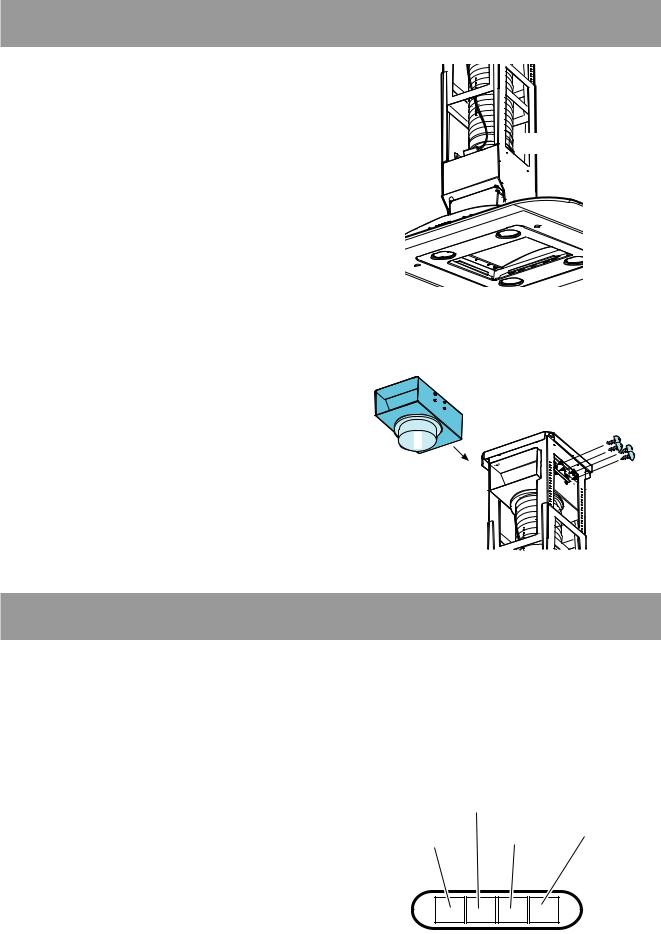
Filter Version
•The air is filtered through a charcoal filter and returned to the kitchen.
•You will need an original ELECTROLUX charcoal filter for the filtering function. (See Special Accessories).
•Fix the deflector using 4 screws Ø 3.5x13 mm.
Fig. 2.
Attention!
The deflector and the relative fixing screws are not supplied when the upper section of the chimney has no side slots.
Fig. 1
F
Fig. 2
Control Panel - EFC 1460
•Best results are obtained by using a low speed for normal conditions and a high speed when odours are more concentrated.
Turn the hood on a few minutes before you start cooking, you will then get an under pressure in the kitchen. The hood should be left on after cooking for about 15 minutes or until all the odours have disappeared. The control switches are located on the unit’s front panel:
•the light switch switches the hood lamp ON and OFF;
•ON/OFF Extractor fan switch - Push-button 1: used to turn the fan off and to set the fan to speed 1.
•Push-button 2: used to set the fan to speed 2.
•Push-button 3: used to set the fan to speed 3.
ON/OFF Extractor fan
switch - Push-button 1
Light switch
Push-button Push-button 3
2
Correct ventilation
If the cooker hood is to work correctly there must be an under pressure in the kitchen. It is important
to keep the kitchen windows closed and have a Fig. 3 window in an adjacent room open.
43

Control Panel - EFC 1420
•Best results are obtained by using a low speed for normal conditions and a high speed when odours are more concentrated.
Turn the hood on a few minutes before you start cooking, you will then get an under pressure in the kitchen. The hood should be left on after cooking for about 15 minutes or until all the odours have disappeared. The control switches are located on the unit’s front panel:
A B C D E F G H I
Fig. 4
A- Main switch, hood off.
B- Start and choice of motor speed 1-2-3-1- 2.........
C- Indicates speed 1 (LED).
D- Indicates speed 2 and saturation of the grease filter (LED)
E- Indicates speed 3 and saturation of the charcoal filter (LED) (flashing LED)
F- Indicates Intensive speed (LED).
G- Intensive speed on/off. The Intensive speed runs for 5 minutes:
If the hood is on when the Intensive speed is activated, the hood reverts to previous speed after 5 minutes.
If the hood is off when the Intensive speed is activated, the hood will be turned off after 5 minutes.
To interrupt the Intensive speed, press button A or B.
H- Light OFF
I- Light ON
Should the hood or the controls fail to operate: disconnect the power supply for at least 5 seconds, then turn the hood back on again.
indicator light must be enabled as follows: Press buttons B and G simultaneously and hold
them for 3 seconds. At first only the grease filter LED D will light up, but when the charcoal filter LED E lights up the saturation indicator will be enabled.
To disable it: Press buttons B and G again simultaneously and hold
them for 3 seconds, until the charcoal filter LED goes out.
Grease filter LED (D)
LED D will start to flash when it is time to clean the grease filter.
Cleaning will be necessary after 40 working hours. Always comply with the maintenance instructions for the grease filter.
Charcoal filter LED (E)
The charcoal filter LED E will start to flash when the charcoal filter needs to be replaced.
This operation is necessary after approximately 160 working hours.
Control device for grease and charcoal filters
This hood is fitted with a device that signals when it is necessary to clean the grease filter or the charcoal filter (in the case of recirculation version with charcoal filter).
On delivery, the hood is not supplied with an charcoal filter, so the saturation indicator will be disabled.
If the hood is to be used with a charcoal filter, the saturation
Correct ventilation
If the cooker hood is to work correctly there must be an under pressure in the kitchen. It is important to keep the kitchen windows closed and have a window in an adjacent room open.
44
 Loading...