


EFA 12545
Instructions Manual
Manual de instrucciones
Manual de Instruções

Instructions Manual |
|
INDEX |
|
RECOMMENDATIONS AND SUGGESTIONS |
......................................................................................................................5 |
CHARACTERISTICS.............................................................................................................................................................. |
6 |
INSTALLATION ...................................................................................................................................................................... |
8 |
USE....................................................................................................................................................................................... |
12 |
MAINTENANCE.................................................................................................................................................................... |
14 |
EN |
|
2 |
|
2 |

Manual de instrucciones |
|
ÍNDICE |
|
CONSEJOS Y SUGERENCIAS ........................................................................................................................................... |
16 |
CARACTERÍSTICAS ............................................................................................................................................................ |
17 |
INSTALACIÓN...................................................................................................................................................................... |
19 |
USO ...................................................................................................................................................................................... |
23 |
MANTENIMIENTO................................................................................................................................................................ |
25 |
ES |
|
3 |
|
3 |

Manual de Instruções |
|
ÍNDICE |
|
CONSELHOS E SUGESTÕES ............................................................................................................................................ |
27 |
CARACTERÍSTICAS ............................................................................................................................................................ |
28 |
INSTALAÇÃO ....................................................................................................................................................................... |
30 |
UTILIZAÇÃO......................................................................................................................................................................... |
34 |
MANUTENÇÃO .................................................................................................................................................................... |
36 |
PT |
|
4 |
|
4 |
RECOMMENDATIONS AND SUGGESTIONS
 The Instructions for Use apply to several versions of this appliance. Accordingly, you may find descriptions of individual features that do not apply to your specific appliance.
INSTALLATION
• The manufacturer will not be held liable for any damages resulting from incorrect or improper installation.
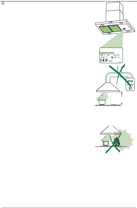
•The minimum safety distance between the cooker top and the extractor hood is 650 mm.
•Check that the mains voltage corresponds to that indicated on the rating plate fixed to the inside of the hood.
•For Class I appliances, check that the domestic power supply guarantees
adequate earthing.
Connect the extractor to the exhaust flue through a pipe of minimum diameter 120 mm. The route of the flue must be as short as possible.
•Do not connect the extractor hood to exhaust ducts carrying combustion fumes (boilers, fireplaces, etc.).
•If the extractor is used in conjunction with non-electrical appliances (e.g.
gas burning appliances), a sufficient degree of aeration must be guaranteed in the room in order to prevent the backflow of exhaust gas. The kitchen must have an opening communicating directly with the open air in order to guarantee the entry of clean air.
USE
• The extractor hood has been designed exclusively for domestic use to |
650 mm min. |
|
eliminate kitchen smells. |
|
|
|
|
|
•Never use the hood for purposes other than for which it has ben designed.
•Never leave high naked flames under the hood when it is in operation.
•Adjust the flame intensity to direct it onto the bottom of the pan only, making sure that it does not engulf the sides.
•Deep fat fryers must be continuously monitored during use: overheated oil can burst into flames.
•Do not flambè under the range hood; risk of fire
• This appliance is not intended for use by persons (including children) with reduced physical, sensory or mental capabilities, or lack of experience and knowledge, unless they have been given supervision or instruction concerning use of the appliance by a person responsible for their safety.
•Children should be supervised to ensure that they do not play with the appliance
MAINTENANCE
•Switch off or unplug the appliance from the mains supply before carrying out any maintenance work.
•Clean and/or replace the Filters after the specified time period.
•Clean the hood using a damp cloth and a neutral liquid detergent.
EN |
|
5 |
|
5 |

CHARACTERISTICS
Dimensions
650 min.
|
|
|
|
|
|
|
|
|
|
|
|
|
|
|
|
|
|
|
|
|
|
|
|
|
|
|
|
|
|
|
|
|
|
|
|
|
|
|
|
|
|
|
|
|
|
|
|
|
|
|
|
|
|
|
|
|
|
|
|
|
|
|
|
|
|
|
|
|
|
|
|
|
|
|
|
|
|
|
|
|
|
|
|
|
|
|
|
|
|
|
|
|
|
|
|
|
|
|
|
|
|
|
|
|
|
|
|
|
|
|
|
|
|
|
|
|
|
|
|
EN |
|
|
|
|
|
|
6 |
||||
|
|
|
|
|
|
6 |
|||||
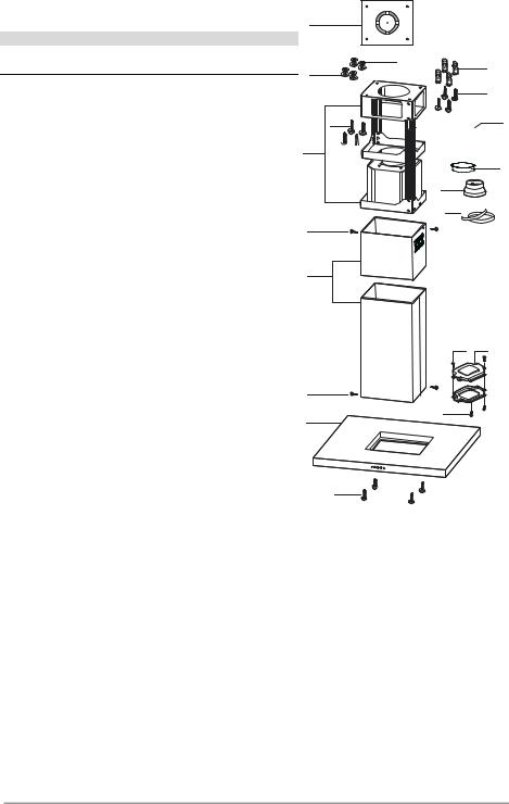
Components |
21 |
|
Ref. Q.ty Product Components
11 Hood Body, complete with: Controls, Light, Blower, Filters
2 |
1 |
Telescopic Chimney comprising: |
2.1 |
1 |
Upper Section |
2.2 |
1 |
Lower Section |
7.1 |
1 |
Telescopic frame complete with extractor, consisting of: |
7.1a |
1 |
Upper frame |
7.1b |
1 |
Lower frame |
9 |
1 |
Reducer Flange ø 150-120 mm |
10 |
1 |
Flange ø 150 |
15 |
1 |
Air Outlet Connection |
24 |
1 |
Junction box |
25 |
2 |
Pipe clamps |
|
|
|
Ref. |
Q.ty |
Installation Components |
11 |
4 |
Wall Plugs ø 10 |
12c |
6 |
Screws 2,9 x 6,5 |
12e |
2 |
Screws 2,9 x 9,5 |
12f |
4 |
Screws M6 x 10 |
12g |
4 |
Screws M6 x 80 |
12h |
4 |
Screws 5,2 x 70 |
21 |
1 |
Drilling template |
22 |
4 |
6.4 mm int. dia washers |
23 |
4 |
M6 nuts |
|
|
|
|
Q.ty |
Documentation |
|
1 |
Instruction Manual |
|
23 |
11 |
22 |
|
|
|
|
|
7.1a |
|
12h |
|
|
|
12g |
|
15 |
7.1 


 10
10
9
7.1b
25 
12c
2.1
2
2.2
12e 24
12c
12c
1
12f
EN |
|
7 |
|
7 |

INSTALLATION
Drilling the Ceiling/shelf and fixing the frame
DRILLING THE CEILING/SHELF
•Use a plumb line to mark the centre of the hob on the ceiling/support shelf.
•Place the drilling template 21 provided on the ceiling/support shelf, making sure that the template is in the correct position by lining up the axes of the template with those of the hob.
•Mark the centres of the holes in the template.
•Drill the holes at the points marked:
•For concrete ceilings, drill for plugs appropriate to the screw size.
•For hollow brick ceilings with wall thickness of 20 mm: drill ø 10 mm(immediately insert the Dowels 11 supplied).
•For wooden beam ceilings, drill according to the wood screws used.
•For wooden shelf, drill ø 7 mm.
•For the power supply cable feed, drill ø 10 mm.
•For the air outlet (Ducted Version), drill according to the diameter of the external air exhaust duct connection.
•Insert two screws of the following type, crossing them and leaving 4-5 mm from the ceiling:
•For concrete ceilings, use the appropriate plugs for the screw size (not provided).
•for Cavity ceiling with inner space, with wall thickness of approx. 20 mm, Screws 12h, supplied.
•For wooden beam ceilings, use 4 wood screws (not provided).
•For wooden shelf, use 4 screws 12g with washers 22 and nuts 23, provided.
EN |
|
8 |
|
8 |
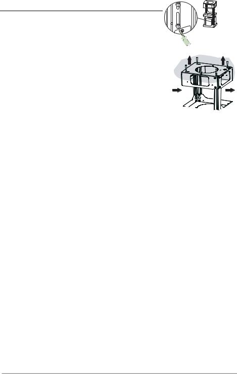
Fixing the frame
• |
Loosen the two screws |
fastening the lower chimney and re- |
|
|
|
move this from the lower frame. |
|
|
|
• |
Loosen the two screws |
fastening the upper chimney and re- |
|
|
|
move this from the upper frame. |
|
|
|
If you wish to adjust the height of the frame, proceed as follows: |
|
|||
• |
Unfasten the eight metric screws joining the two columns, lo- |
|
||
|
cated at the sides of the frame. |
1 |
1 |
|
• |
Adjust the frame to the height required, |
then replace all the |
|
|
|
screws removed as above. |
|
|
|
• |
Insert the upper chimney stack from above, and leave it run- |
|
||
|
ning free on the frame. |
|
2 |
2 |
• |
Lift up the frame, fit the frame slots onto the screws up to the |
|
||
|
slot end positions. |
|
|
|
•Tighten the two screws and fasten the other two screws provided with the hood.
Before tightening the screws completely it is possible to adjust the frame by turning it. Make sure that the screws do not come out of their seats in the slotted holes.
•The frame mountings must be secure to withstand the weight of the hood and any stresses caused by the occasional side thrust applied to the device.
On completion, check that the base is stable, even if the frame is subjected to bending.
•In all cases where the ceiling is not strong enough at the suspension point, the installer must provide strengthening using suitable plates and backing pieces anchored to the structurally sound parts.
EN |
|
9 |
|
9 |
Connections
DUCTED VERSION AIR EXHAUST SYSTEM
When installing the ducted version, connect the hood to the chimney using either a flexible or rigid pipe ø 150 or 120 mm, the choice of which is left to the installer.
•To install a ø 120 mm air exhaust connection, insert the reducer flange 9 on the hood body outlet.
•Fix the pipe in position using sufficient pipe clamps (not supplied).
•Remove possible charcoal filters.
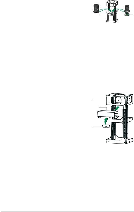
Recirculation version air outlet
•Fix the connection 15 to the frame using the 4 screws provided.
•Fix the flange 10 to the lower opening of the connection 15.
•Connect the hood air outlet to the flange in the lower part of the junction using a rigid or flexible ø 150 tube (by installer’s choice).
ø 150
25
15
10
ø 120
25
9
EN |
|
1 |
|
10 |
Flue assembly - Mounting the hood body |
12c |
|
• Position the upper chimney section and fix the upper part to the frame using the 2 screws 12c (2,9 x 6,5) provided.
• Similarly, position the lower chimney section and fix the lower part to the frame using the 2 screws 12c (2,9 x 6,5) provided.
Before fixing the hood body to the frame:
•Remove the grease filters from the hood body.
•Remove any activated charcoal filters.
•From below, use the 4 screws 12f (M6 x 10)provided to fix the hood body to the frame.
ELECTRICAL CONNECTION
•Connect the hood to the mains through a two-pole switch having a contact gap of at least 3 mm.
•Remove the grease filters (see paragraph Maintenance) being sure that the connector of the feeding cable is correctly inserted in the socket placed on the side of the fan.
•Connect the control connector Cmd.
•Connect the lights connector Lux.
•Place the connectors in the junction box 24 and close it using the 2 screws 12e (2,9 x 9,5) provided.
•Fix the junction box to the hood body using the 2 screws 12c (2,9 x 6,5) provided.
•For the recirculation version, fit the activated carbon odour filter.
•Replace the grease filters.
12c
12f
24
12e |
|
|
Lux |
12c |
Cmd |
EN |
|
1 |
|
11 |
USE
L T1 T2 T3 T4 T5 F
The hood can be switched on pushing directly onto the requested speed without firstly having to select 0/1 button .
Touch |
Basic functions |
|
|
Indicator lights |
|
control |
|
|
|
|
|
Dual Function |
|
|
|
|
|
|
|
|
|
|
|
L |
When briefly pressed it switches the lighting system |
Touch control unlit |
Lights off |
||
|
on and off. |
|
|
|
|
|
When pressed for 2 seconds it starts the lighting |
Touch control lit |
Lights on |
||
|
system in “courtesy light” mode. The lamps are |
|
|
||
|
fed at a reduced power of approximately 5W. |
|
|
||
|
Such function can be stopped by pressing the |
|
|
||
|
Touch control unlit |
Courtesy light on |
|||
|
touch control for 2 seconds or just by pressing it |
||||
|
|
|
|||
|
shortly in order to return to the normal lighting |
|
|
||
|
mode. In courtesy light mode the touch control is |
|
|
||
|
not lit. |
|
|
|
|
T1 |
When pressed the motor is stopped, regardless of the |
Touch control lit |
Motor on |
||
|
speed it is set to. |
|
|
Touch control unlit |
Motor off |
|
|
|
|
||
T2 |
When pressed the motor is set to the first speed |
Touch control lit |
|||
|
|
|
|
||
T3 |
By a brief pressing the motor is set to the second |
Touch control lit |
Second speed on |
||
|
speed. |
|
|
|
|
|
By pressing the touch control for approximately 2 |
Flashing touch |
Delay function on |
||
|
seconds the Delay function is enabled, i.e de- |
control |
|
||
|
layed shutdown of the appliance ensuring a com- |
|
|
||
|
plete elimination of the residual odours. This fun- |
|
|
||
|
ction can be activated at OFF-position and at 1°, |
|
|
||
|
2° and 3°speeds. It can be stopped in advance |
|
|
||
|
by pressing any of the touch controls (T) with the |
|
|
||
|
exception of T3. The Delay function works accor- |
|
|
||
|
ding to the following scheme: |
|
|
|
|
|
1°speed / OFF |
= |
20 minuets |
|
|
|
2°speed |
= |
15 minutes |
|
|
|
3°speed |
= |
5 minutes |
|
|
T4 |
When pressed the motor is set to the third speed |
Touch control lit |
|
||
EN |
|
1 |
|
12 |
 Loading...