


Gebrauchsanweisung , Notice d'utilisation et d'installation, Istruzioni per l'uso, User manual
EFC 6940 - EFC 6941
EFC 1410
Installatieen gebruiksaanwijzing, Instrucciones de montaje y manejo, Manual de Instruções
EFC 69406941
EFC 1410
SM 8090
SM 8060
SM 8091 |
SM 8092 |
SM 8093 |
|
||
|
SM 8062 |
|
D F I UK NL E P

Contents
UK
Safety warnings................................................................................................................................................... |
36 |
for the installer ....................................................................................................................................................... |
36 |
for the user ............................................................................................................................................................. |
36 |
Description of the appliance ............................................................................................................................ |
37 |
Extractor version.................................................................................................................................................... |
37 |
Filter Version .......................................................................................................................................................... |
37 |
Control Panel - EFC 6940-6941 ...................................................................................................................... |
38 |
Control Panel - EFC 1410 ................................................................................................................................ |
39 |
Maintenance and care ....................................................................................................................................... |
40 |
Cleaning ................................................................................................................................................................. |
40 |
Metal grease filter .................................................................................................................................................. |
40 |
Charcoal filter ........................................................................................................................................................ |
41 |
Changing the light bulb ........................................................................................................................................... |
41 |
What to do if ....................................................................................................................................................... |
42 |
Technical Specifications .................................................................................................................................... |
42 |
Special accessories ............................................................................................................................................ |
42 |
Technical assistance service............................................................................................................................ |
43 |
Installation .......................................................................................................................................................... |
45 |
Electrical connection .............................................................................................................................................. |
45 |
Mounting accessories included .............................................................................................................................. |
45 |
Wall unit mounting .................................................................................................................................................. |
46 |
Special accessories/Vapour screen ................................................................................................................. |
83 |
Before you use the cooker hood we recommend that you read through the whole user manual giving a direct description of the cooker hood and its functions.
To avoid the risks, that are always present when you use a product driven by electricity, it is important that the cooker hood is installed correctly and that you read the safety instructions carefully to avoid misuse and hazard. Save the instruction manual and keep it available at use of the cooker hood
35

 Safety warnings
for the installer
•When used as an extractor unit, the hood must be fitted with a 150mm diameter hose.
•Should there already be a pipe of diameter 125 mm that ducts to the outside through the walls or roof, it is possible to use the 150/125 mm reduction flange provided. In this case the hood will be slightly more noisy.
•When installing the hood, make sure you respect the following minimum distance
from the top edge of the cooking hob/ring surfaces:
electric cookers |
500 |
mm |
gas cookers |
650 |
mm |
coal and oil cookers |
700 mm min. |
|
•The national standard on fuel-burning systems specifies a maximum depression of 0.04 bar in such rooms.
•The air outlet must not be connected to chimney flues or combustion gas ducts. The air outlet must under no circumstances be connected to ventilation ducts for rooms in which fuel-burning appliances are installed.
•It is advisable to apply for authorization from the relevant controlling authority when connecting the outlet to an unused chimney flue or combustion gas duct.
The air outlet installation must comply with the regulations laid down by the relevant authorities.
•When the unit is used in its extractor version, a sufficiently large ventilation hole must be provided, with dimensions that are approximately the same as the outlet hole.
•National and regional building regulations impose a number of restrictions on using hoods and fuel-burning appliances connected to a chimney, such as coal or oil room-heaters and gas fires, in the same room.
•Hoods can only be used safely with appliances connected to a chimney if the room and/or flat (air/environment combination) is ventilated from outside using a suitable ventilation hole approximately 500-600 cm2 large to avoid the possibility of a depression being created during operation of the hood.
•If you have any doubts, contact the relevant controlling authority or building inspector’s office.
•Since the rule for rooms with fuel burning appliances is “outlet hole of the same size as the ventilation hole”, a hole of 500-600 cm2, which
is to say a larger hole, could reduce the performance of the extractor hood.
•If the hood is used in its filtering function, it will operate simply and safely in the above conditions without the need for any of the aforementioned measures.
•When the hood is used in its extractor function, the following rules must be followed to obtain optimal operation:
—short and straight outlet hose
—keep bends in outlet hose to a minimum
—never install the hoses with an acute angle, they must always follow a gentle curve only
—keep the hose as large as possible (preferably the same diameter as the outlet hole).
•Failure to observe these basic instructions will drastically reduce the performance and increase the noise levels of the extractor hood.
for the user
•Always cover lighted elements, to prevent excess heat from damaging the appliance. In the case of oil, gas and coal fired cookers it is essential to avoid open flames.
•Also, when frying, keep the deep frying pan on the cooker top/cooker under careful control.
•The hot oil in the frying pan might ignite due to overheating.
•The risk of self-ignition increases when the oil being used is dirty.
•It is extremely important to note that overheating can cause a fire.
•Never carry out any flambé cooking under the hood.
•Always disconnect the unit from the power supply before carrying out any work on the hood, including replacing the light bulb
(take the cartridge fuse out of the fuse holder or switch off the automatic circuit breaker).
•It is very important to clean the hood and replace the filter at the recommended intervals. Failure to do so could cause grease deposits to build up, resulting in a fire hazard.
36
Description of the appliance
Extractor version
•The hood is supplied as an extractor unit and can also be used with a filtering function by fitting one charcoal filter (special accessory).
•You will need original ELECTROLUX charcoal filter for this function (see Special Accessories).
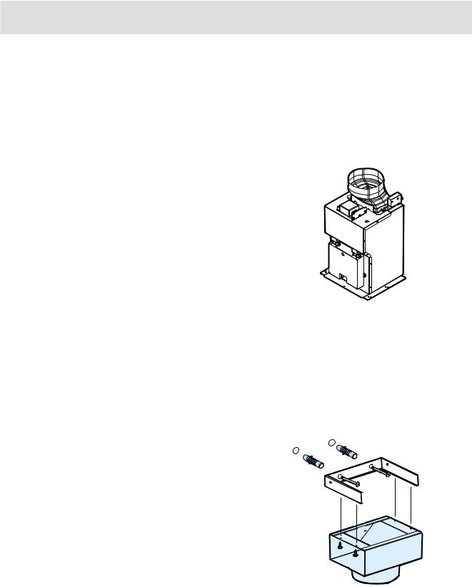
•The air is discharged to the outside through a pipe, which must be fitted to connection flange
D. Fig. 1.
• In order to obtain the best performance the hose D 
 should have a diameter equal to the outlet hole.
Should there already be a pipe of diameter 125 mm that ducts to the outside through the walls or roof, it is possible to use the 150/125 mm reduction flange provided. In this case the hood will be slightly more noisier.
Filter Version
•The air is filtered through a charcoal filter and returned to the kitchen through the top grill of the outlet pipe.
•You will need an original ELECTROLUX Type 20 charcoal filter for the filtering function. (See Special Accessories).
•Fix the deflector using 4 screws Ø 2,9x6.5 mm.
Fig. 2.
•Optionally, the position of the chimney elements can be changed.
When using the hood in the filter version the chimney must be fixed at the top, with the air outlet grill at the side.
Fig. 1
Fig. 2
37

Control Panel - EFC 6940-6941
•The hood is fitted with one motor having several speed. Turn the hood on a few minutes before you start cooking, you will then get an under pressure in the kitchen. The hood should be left on after cooking for about 15 minutes or until all the odours have disappeared.
The control switches are located on the unit’s front panel:
•The hood operation may be controlled via the control ball or with the remote control (the remote control is a special accessory and is ordered separately).
Every status change (changing speed, switching on the lights, etc.) and is recognizable from the variation of light emitted by the control ball and by an acoustic signal.
The control ball serves also as a light signal :
•No signal :
The hood is switched off.
•Static green light :
Hood is switched on at power level 1 (minimum).
•Static orange light :
Hood is switched on at power level 2 (medium).
•Static red light :
Hood is switched on at power level 3 (maximum).
•Alternating red light :
Hood is switched on at intensive power level (timed at 5 minutes)
•Alternating green light :
Indicates the grease filter saturation - clean the grease filter
•Alternating orange light :
Indicates the charcoal filter saturation - clean or replace the charcoal filter
Attention!
The control Ball flashes orange to indicate the saturation of the odor filter even when the charcoal filter is not installed inside the cooker hood.
However perform the signal reset operation as follows: select the intensive speed (the control ball lights up with a red flashing light), depress again and hold depressed for about 3 seconds until a ‘bip’ sound indicates the reset.
depress towards |
|
depress towards |
||||||
the right to switch |
|
the left to switch |
||||||
on the hood |
|
on the light. |
||||||
|
|
|
|
|
|
|
|
|
|
|
|
|
|
|
|
|
|
|
|
|
|
|
|
|
|
|
Fig. 3
Control device for grease or charcoal filter
The air duct, in this hood, is provided with a device that signals when the filter requires cleaning or changing .
Led signal for grease filter
The LED signal flickers (flickering green light) when the grease filter requires cleaning, occurs at about 40 operating hours.
Carefully note the device for grease filter maintenance!
Led signal for charcoal filter
The LED signal flickers (flickering orange light) when the grease filter requires cleaning, occurs at about 160 operating hours.
Carefully note the device for charcoal filter maintenance!
Switching on the hood - Fig. 3
The control ball is a balancer switch.
Depressing the control ball repeatedly towards the right switches on the hood and you may select the suction level desired, depressing once again on the right the hood switches off.
Switching on the light - Fig. 3
Depress the control ball towards the left : once for submersed lighting,
once again for full lighting,
depress again to switch off the light.
Resetting the saturation indicator
After cleaning or replacing the filter, select the intensive speed (the control ball lights up with a red flashing light), depress again and hold depressed for about 3 seconds until a ‘bip’ sound indicates the reset.
Correct ventilation
If the cooker hood is to work correctly there must be an under pressure in the kitchen. It is important to keep the kitchen windows closed and have a window in an adjacent room open
38
 Loading...