


OPERATING INSTRUCTIONS
Index |
|
Safety Precautions .................................. |
2 |
Vehicle Service Information .................... |
3 |
Visual Inspection ..................................... |
3 |
Electrical Specifications ........................ |
32 |
Warranty ................................................ |
96 |
1. Multimeter Basic Functions |
|
Functions and Display Definitions ...... |
4 |
Setting the Range ............................... |
6 |
Battery and Fuse Replacement .......... |
7 |
Measuring DC Voltage ........................ |
8 |
Measuring AC Voltage ........................ |
8 |
Measuring Resistance ........................ |
9 |
Measuring DC Current ...................... |
10 |
Testing Diodes .................................. |
11 |
Testing Batteries ............................... |
12 |
2. Automotive Testing with the CP7665 |
|
General Testing ................................. |
13 |
- Testing Fuses ................................. |
13 |
- Testing Switches ............................. |
13 |
- Testing Solenoids and Relays ........ |
14 |
CP7665
Starting / Charging System Testing . 15 |
|
- No Load Battery Test ...................... |
15 |
- Engine Off Battery Current Draw ... |
16 |
- Cranking Voltage/Battery Load Test . 17 |
|
- Voltage Drops ................................. |
18 |
- Charging System Voltage Test ...... |
19 |
Ignition System Testing .................... |
21 |
- Ignition Coil Testing ........................ |
21 |
- Ignition System Wires ..................... |
23 |
- Magnetic Pick-Up Coils .................. |
24 |
- Reluctance Sensors ........................ |
24 |
Fuel System Testing ......................... |
25 |
- Measuring Fuel Injector Resistance .. |
25 |
Testing Engine Sensors .................... |
27 |
- Oxygen (O2) Type Sensors............. |
27 |
- Temperature Type Sensors ............ |
29 |
-Position Type Sensors – Throttle and EGR Valve Position,
Vane Air Flow .................................. |
30 |
Instrucciones en español .... |
33 |
Instructions en français....... |
65 |
1

SAFETY GUIDELINES
TO PREVENT ACCIDENTS THAT COULD RESULT IN SERIOUS INJURY AND/OR DAMAGE TO YOUR VEHICLE OR TEST EQUIPMENT, CAREFULLY FOLLOW THESE SAFETY RULES AND TEST PROCEDURES
•Always wear approved eye protection.
•Always operate the vehicle in a well ventilated area. Do not inhale exhaust gases – they are very poisonous!
•Always keep yourself, tools and test equipment away from all moving or hot engine parts.
•Always make sure the vehicle is in park (Automatic transmission) or neutral (manual transmission) and that the parking brake is firmly set. Block the drive wheels.
•Never lay tools on vehicle battery. You may short the terminals together causing harm to yourself, the tools or the battery.
•Never smoke or have open flames near vehicle. Vapors from gasoline
and charging battery are highly flammable and explosive.
•Never leave vehicle unattended while running tests.
•Always keep a fire extinguisher suitable for gasoline/electrical/ chemical fires handy.
•Always use extreme caution when working around the ignition coil, distributor cap, ignition wires, and spark plugs. These components contain High Voltage when the engine is running.
•Always turn ignition key OFF when connecting or disconnecting electrical components, unless otherwise instructed.
•Always follow vehicle manufacturer’s warnings, cautions and service procedures.
CAUTION:
Some vehicles are equipped with safety air bags. You must follow vehicle service manual cautions when working around the air bag components or wiring. If the cautions are not followed, the air bag may open up unexpectedly, resulting in personal injury. Note that the air bag can still open up several minutes after the ignition key is off (or even if the vehicle battery is disconnected) because of a special energy reserve module.
All information, illustrations and specifications contained in this manual are based on the latest information available from industry sources at the time of publication. No warranty (expressed or implied) can be made for its accuracy or completeness, nor is any responsibility assumed by Actron Manufacturing Co. or anyone connected with it for loss or damages suffered through reliance on any information contained in this manual or misuse of accompanying product. Actron Manufacturing Co. reserves the right to make changes at any time to this manual or accompanying product without obligation to notify any person or organization of such changes.
2
Vehicle Service Manual – Sources For Service
Information
The following is a list of sources to obtain vehicle service information for your specific vehicle.
•Contact your local Automotive Dealership Parts Department.
•Contact local retail auto parts stores for aftermarket vehicle service information.
•Contact your local library. Libraries often allow you to check-out automotive service manuals.
Do a Thorough Visual Inspection
Do a thorough visual and “hands-on” underhood inspection before starting any diagnostic procedure! You can find the cause of many problems by just looking, thereby saving yourself a lot of time.
•Has the vehicle been serviced recently? Sometimes things get reconnected in the wrong place, or not at all.
•Don’t take shortcuts. Inspect hoses and wiring which may be difficult to see due to location.
•Inspect the air cleaner and ductwork for defects.
•Check sensors and actuators for damage.
•Inspect ignition wires for:
-Damaged terminals.
-Split or cracked spark plug boots
-Splits, cuts or breaks in the ignition wires and insulation.
•Inspect all vacuum hoses for:
-Correct routing. Refer to vehicle service manual, or Ve-
hicle Emission Control Information(VECI) decal located in the engine compartment.
-Pinches and kinks.
-Splits, cuts or breaks.
•Inspect wiring for:
-Contact with sharp edges.
-Contact with hot surfaces, such as exhaust manifolds.
-Pinched, burned or chafed insulation.
-Proper routing and connections.
•Check electrical connectors for:
-Corrosion on pins.
-Bent or damaged pins.
-Contacts not properly seated in housing.
-Bad wire crimps to terminals.
3
Section 1. Multimeter Basic Functions
Digital multimeters or DMMs have many special features and functions. This section defines these features and functions, and explains how to use these functions to make various measurements.
1
11
5 |
10 |
3


 2 8
2 8 


 7 4
7 4 


 9 6
9 6 
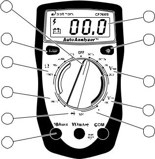
Functions and Display Definitions
1.ROTARY SWITCH
Switch is rotated to turn multimeter ON/OFF and select a function.
2.DC VOLTS
This function is used for measuring DC (Direct Current) Voltages in the range of 0 to 500V.
3.OHMS
This function is used for measur-
ing the resistance of a component in an electrical circuit in the range of 0.1Ω to 20MΩ . (Ω is the electrical symbol for Ohms)
4.DIODE CHECK
This function is used to check whether a diode is good or bad.
5.HOLD
Press HOLD button to retain data
4

on display. In the hold mode, the "H" annunciator is displayed.
6.TEST LEAD JACKS BLACK Test Lead is always inserted in the COM jack.
RED Test Lead is inserted in the jack cor-
responding to the multimeter rotary switch setting.
Always connect TEST LEADS to the multimeter before connecting them to the circuit under test!!
DC AMPS |
DC VOLTS |
AC VOLTS |
|
OHMS |
DIODES |
|
1.5V, 9V and 12V |
|
|
BATTERY TESTS |
|
7.AC VOLTS
This function is used for measuring AC Voltages in the range of 0 to 500V.
8.DC AMPS
This function is used for measuring DC (Direct Current) Amps in the range of 0 to 10A.
9.1.5V, 9V, AND 12V BATTERY TEST
This function is used to test 1.5V, 9V, and 12V batteries under load.
10.DISPLAY LIGHT
Press button to illuminate the display.
11.DISPLAY
Used to display all measurements and multimeter information.
Low Battery – If this symbol appears in the lower left corner of the display, then replace the internal
9V battery. (See Fuse and Battery
replacement on page 7.)
High Voltage indicator
Overrange Indication – If “1” or “- 1” appears on the left side of the display, then the multimeter is set to a range that is too small for the present measurement being taken.
Increase the range until this disappears. If it does not disappear after all the ranges for a particular function have been tried, then the value being measured is too large for the multimeter to measure. (See Setting the Range on page 6.)
Zero Adjustment
The multimeter will automatically zero on the Volts, Amps and Battery Test functions.
Automatic Polarity Sensing
The multimeter display will show a minus (-) sign on the DC Volts and DC Amps functions when test lead hook-up is reversed.
5

Setting the Range
Two of the most commonly asked questions about digital multimeters are What does Range mean? and How do I know what Range the multimeter should be set to?
What Does Range mean?
Range refers to the largest value the multimeter can measure with the rotary switch in that position. If the multimeter is set to the 20V DC range, then the highest voltage the multimeter can measure is 20V in that range.
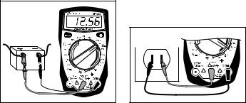
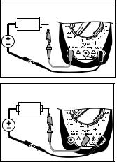
EXAMPLE: Measuring Vehicle Battery Voltage (See Fig. 1)
Fig. 1
Red Black
Let’s assume the multimeter is connected to the battery and set to the 20V range.
The display reads 12.56. This means there is 12.56V across the battery terminals.
Now assume we set the multimeter to the 2000mV range. (See Fig. 2)
The multimeter display now shows a “1” and nothing else. This means the multimeter is being overranged or in other words the value being measured is larger than the current range. The range should be increased until a value is shown on
Fig. 2
Red
Black
the display. If you are in the highest range and the multimeter is still showing that it is overranging, then the value being measured is too large for the multimeter to measure.
How do I know what Range the multimeter should be set to?
The multimeter should be set in the lowest possible range without overranging.
EXAMPLE: Measuring an unknown resistance
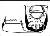
Let’s assume the multimeter is connected to an engine coolant sensor with unknown resistance. (See Fig. 3)
Start by setting the multimeter to the largest OHM range. The display reads 0.0Ω or a short circuit.
Fig. 3
Red  Black
Black
6
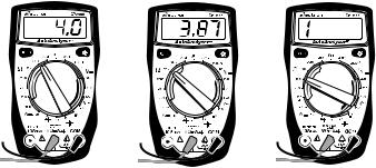
Fig. 4 |
|
Fig. 5 |
|
Fig. 6 |
|
|
|
|
|
This sensor can’t be shorted so reduce the range setting until you get a value of resistance.
At the 200KΩ range the multimeter measured a value of 4.0. This means there is 4KΩ of resistance across the engine coolant sensor terminals. (See Fig. 4)
If we change the multimeter to the 20KΩ range (See Fig. 5) the display shows a value of 3.87KΩ . The actual value of resistance is 3.87KΩ and not 4KΩ that was measured in the 200KΩ range. This is very important because if the manufacturer specifications say that the sensor should read 3.8-3.9KΩ at 70° F then on the 200KΩ range the sensor would be defective, but at the 20KΩ range it would test good.
Now set the multimeter to the 2000Ω range. (See Fig. 6) The display will indicate an overrange condition because 3.87KΩ is larger than 2KΩ .
This example shows that by decreasing the range you increase the accuracy of your measurement. When you change the range, you change the location of the decimal point. This changes the accuracy of the measurement by either increas-
ing or decreasing the number of digits after the decimal point.
Battery and Fuse
Replacement
Important: A 9 Volt battery must be installed before using the digital multimeter. (see procedure below for installation)
Battery Replacement
1.Turn multimeter rotary switch to OFF position.
2.Remove test leads from multimeter.
3.Remove screws from back of multimeter.
4.Remove back cover.
5.Install a new 9 Volt battery.
6.Re-assemble multimeter.
Fuse Replacement
1.Turn multimeter rotary switch to OFF position.
2.Remove test leads from multimeter.
7
3.Remove screws from back of multimeter.
4.Remove back cover.
5.Remove fuse.
6.Replace fuse with same size and type as originally installed!
5mm x 20mm, 200mA, 250V, fast acting.
7.Re-assemble multimeter.
Measuring DC Voltage
This multimeter can be used to measure DC voltages in the range from 0 to 500V. You can use this multimeter to do any DC voltage measurement called out in the vehicle service manual. The most common applications are measuring voltage drops, and checking if the correct voltage arrived at or is being produced by a sensor or a particular circuit.
To measure DC Voltages (see Fig. 7):
1.Insert BLACK test lead into COM test lead jack.
2.Insert RED test lead into 

 test lead jack.
3.Connect RED test lead to positive (+) side of voltage source.
4.Connect BLACK test lead to
Fig. 7
Red Black
negative (-) side of voltage source.
NOTE: If you don’t know which side is positive (+) and which side is negative (-), then arbitrarily connect the RED test lead to one side and the BLACK to the other. The multimeter automatically senses polarity and will display a minus (-) sign when negative polarity is measured. If you switch the RED and BLACK test leads, positive polarity will now be indicated on the display. Measuring negative voltages causes no harm to the multimeter.
5.Turn multimeter rotary switch to desired voltage range.
If the approximate voltage is unknown, start at the largest voltage range and decrease to the appropriate range as required. (See Setting the Range on page 6)
6.View reading on display - Note range setting for correct units.
NOTE: 200mV = 0.2V
Measuring AC Voltage
This multimeter can be used to measure AC voltages in the range from 0 to 500V.
To measure AC Voltages (see Fig. 8):
Fig. 8 |
Red |
Black |
8
1.Insert BLACK test lead into COM test lead jack.
2.Insert RED test lead into 

 test lead jack.
3.Connect RED test lead to one side of voltage source.
4.Connect BLACK test lead to other side of voltage source.
5.Turn multimeter rotary switch to desired voltage range.
If the approximate voltage is unknown, start at the largest voltage range and decrease to the appropriate range as required. (See Setting the Range on page 6)
6.View reading on display.
NOTE: 200mV = 0.2V
Measuring Resistance
Resistance is measured in electrical units called ohms (Ω ). The digital multimeter can measure resistance from 0.1Ω to 20MΩ (or 20,000,000 ohms). Infinite resistance is shown with a “1” on the left side of display (See Setting the Range on page 6). You can use this multimeter to do any resistance measurement called out in the vehicle service manual. Testing ignition coils, spark plug wires, and some engine sensors are common uses for the OHMS (Ω ) function.
To measure Resistance (see Fig. 9):
1.Turn circuit power OFF.
To get an accurate resistance measurement and avoid possible damage to the digital multimeter and electrical circuit under test, turn off all electrical power in the circuit where the resistance measurement is being taken.
Fig. 9 |
|
Unknown |
|
Resistance |
|
Black |
Red |
2.Insert BLACK test lead into COM test lead jack.
3.Insert RED test lead into 

 test lead jack.
4.Turn multimeter rotary switch to 200Ω range.
Touch RED and BLACK multimeter leads together and view reading on display.
Display should read typically 0.2Ω to 1.5Ω .
If display reading was greater than 1.5Ω , check both ends of test leads for bad connections. If bad connections are found, replace test leads.
5.Connect RED and BLACK test leads across component where you want to measure resistance.
When making resistance measurements, polarity is not important. The test leads just have to be connected across the component.
6.Turn multimeter rotary switch to desired OHM range.
If the approximate resistance is unknown, start at the largest OHM range and decrease to the appropriate range as required. (See Setting the Range on page 6)
9
7.View reading on display - Note range setting for correct units.
NOTE: 2KΩ = 2,000Ω ; 2MΩ = 2,000,000Ω
If you want to make precise resistance measurements, then subtract the test lead resistance found in Step 4 above from the display reading in Step 7. It is a good idea to do this for resis-
tance measurements less than 10Ω .
Measuring DC Current
This multimeter can be used to measure DC current in the range from 0 to 10A. Unlike voltage and resistance measurements where the multimeter is connected across the component you are testing, current measurements must be made with the multimeter in series with the component. Isolating current drains and short circuits are some DC Current applications.
Fig. 10
Electrical
Device
DC
Voltage
Source
Red
Black
Fig. 11
Electrical
Device
DC
Voltage
Source
Red
Black
To measure DC Current (see Figs. 10 & 11):
1.Insert BLACK test lead into COM test lead jack.
2.Insert RED test lead into "10A" test lead jack or "mA" test lead jack.
3.Disconnect or electrically open circuit where you want to measure current.
This is done by:
•Disconnecting wiring harness.
•Disconnecting wire from screw-on type terminal.
•Unsolder lead from component if working on printed circuit boards.
•Cut wire if there is no other possible way to open electrical circuit.
4.Connect RED test lead to one side of disconnected circuit.
5.Connect BLACK test lead to remaining side of disconnected circuit.
6.Turn multimeter rotary switch
to 10A DC position, 200mA or 200 A position.
7.View reading on display.
If minus (-) sign appears on display, then reverse RED and BLACK test leads.
10
 Loading...