


p r e c i s i o n e l e c t r o n i c s o l u t i o n s
CODE SCANNER¨
FAVOR DE LEER INSTRUCTCTIVO ANTES DE USAR EL ARTICULO
Car Computer
Code Reader
Domestic GM & Saturn
Lector de Códigos de Computadoras de Automóvil
GM y Saturn
nacionales de EE.UU. con Systemas MCU y EEC-IV (para EUA)
Instrucciónes
en español - página 99
Lecteur de code d'ordinateur automobile
GM y Saturn domestiques Étas-Unis
avec Systèmes MCU ou EEC-IV
Instructions en français - page 199
Tensión: 14V Para Nombre, Domicilio y Telefono |
CP9001 |
|
Hecho en: China |
del Importador: Ver Empaque |
|
|
|
|
1

2
Congratulations on purchasing your Actron Code Scanner for accessing engine trouble codes required for repairing vehicles equipped with computers. Your Actron Code Scanner is made by Actron, the largest and most trusted name in automotive diagnostic equipment for the home mechanic. You can have confidence this product maintains the highest quality in manufacturing, and will provide you years of reliable service.
This instruction manual is divided into several key sections. You will find detailed steps on using the Code Scanner and important information about trouble code meanings, how a computer controls engine operation, and more!
Identifying the problem is the first step in solving that problem. Your Actron Code Scanner can help you determine by accessing the engine computer trouble codes. Armed with that knowledge, you can either refer to an appropriate service manual or discuss your problem with a knowledgeable service technician. In either event you can save yourself a lot of valuable time and money in auto repair. And feel confident that your vehicle’s problem has been fixed!
Actron offers a compete line of high quality automotive diagnostic and repair equipment. See your local Actron dealer for other Actron products.
CP9001
 ™
™
CONTENTS
Engine/TransmissionSection
1 |
About Codes ................................. |
3 |
2 |
When to Read Codes ................... |
5 |
3 |
Reading Codes ............................. |
6 |
4 |
Using Codes in a Basic |
|
|
Troubleshooting Procedure ........ |
10 |
5 |
Code Meanings .......................... |
14 |
6 |
Additional Code Scanner |
|
|
Diagnostic Features ................... |
22 |
7 |
Computer Basics ........................ |
25 |
8 |
Glossary ..................................... |
31 |
Anti-LockBrake(ABS)Section |
|
|
9 |
ABS Basics ................................. |
38 |
10 |
ABS Safety ................................. |
44 |
11 |
ABS Tips ..................................... |
45 |
12 |
Reading ABS Codes .................. |
47 |
|
System 1: Bosch 2S ......................... |
51 |
|
System 2: Bosch 2U (Version A) ...... |
56 |
|
System 3: Bosch 2U (Version B) ...... |
62 |
|
System 4: Bosch 2U (Version C) ...... |
68 |
|
System 5: Teves Mark II (Version A) |
74 |
|
System 6: Teves Mark II (Version B) |
79 |
|
System 7: Kelsey-Hayes RWAL ....... |
84 |
|
System 8: Kelsey-Hayes 4WAL ........ |
88 |
Applications ................................. |
94 |
|
Instrucciónesenespañol ... 197
Instructionsenfrançais ..... 297
3

General Safety Guidelines to follow when working on vehicles
•Always wear approved eye protection.
•Always operate the vehicle in a well ventilated area.
Do not inhale exhaust gases – they are very poisonous!
•Always keep yourself, tools and test equipment away from all moving or hot engine parts.
•Always make sure the vehicle is in park (Automatic transmission) or neutral (manual transmission) and that the parking brake is firmly set. Block the drive wheels.
•Never leave vehicle unattended while running tests.
•Never lay tools on vehicle battery. You may short the terminals together causing harm to yourself, the tools or the battery.
•Never smoke or have open flames near vehicle.
Vapors from gasoline and charging battery are highly flammable and explosive.
•Always keep a fire extinguisher suitable for gasoline/electrical/ chemical fires handy.
•Always turn ignition key OFF when connecting or disconnecting electrical components, unless otherwise instructed.
•Always follow vehicle manufacturer’s warnings, cautions and service procedures.
CAUTION:
Some vehicles are equipped with safety air bags.
You must follow vehicle service manual cautions when working around the air bag components or wiring. If the cautions are not followed, the air bag may open up unexpectedly, resulting in personal injury. Note that the air bag can still open up several minutes after the ignition key is off (or even if the vehicle battery is disconnected) because of a special energy reserve module.
4
AboutCodes
Where do they come from and what are they for?
Enginecomputerscanfind problems.
The computer system in today’s vehicles does more than control engine operation – it can help you find problems, too! Special testing abilities are permanently programmed into the computer by factory engineers. These tests check the components connected to the computer which are used for (typically): fuel delivery, idle speed control, spark timing and emission systems. Mechanics have used these tests for years. Now you can do the same thing by using the Actron Code Scanner tool!
Enginecomputersperformspecial tests.
The engine computer runs the special tests. The type of testing varies with manufacturer, engine, model year etc. There is no “universal” test that is the same for all vehicles. The tests examine INPUTS (electrical signals going IN to the computer) and OUTPUTS (electrical signals coming OUT of the computer.) Input signals which have “wrong” values or output circuits which don’t behave correctly are noted by the test program and the results are stored in the computer’s memory. These tests are important. The computer can not control the engine properly if it has bad inputs or outputs!
Codenumbersgivetestresults.
The test results are stored by using code numbers, usually called “trouble codes” or “diagnostic codes.” For example, a code 22 might mean “throttle position sensor signal voltage is too low.” Code meanings are listed in Section 4. Specific code definitions vary with manufacturer, engine and model year, so you may want to refer to a vehicle service manual for additional information. These manuals are
available from the manufacturer, other publishers or your local public library. (See Vehicle Service Info on page 4.)
ReadCodeswiththeCode
Scanner.
You obtain trouble codes from the engine computer memory by using the
Actron Code Scanner tool. Refer to section 2 for details. After you get the trouble codes, you can either:
•Have your vehicle professionally serviced. Trouble codes indicate problems found by the computer.
or,
•Repair the vehicle yourself using trouble codes to help pinpoint the problem.
TroubleCodesandDiagnostics helpyoufixtheproblem.
To find the problem cause yourself, you need perform special test procedures called “diagnostics”. These procedures are in the vehicle service manual. There are many possible causes for any problem. For example, suppose you turned on a wall switch in your home and the ceiling light did not turn on. Is it a bad bulb or light socket? Is the bulb installed correctly? Are there problems with the wiring or wall switch? Maybe there is no power coming into the house! As you can see, there are many possible causes. The diagnostics written for servicing a particular trouble code take into account all the possibilities. If you follow these procedures, you should be able to find the problem causing the code and fix it if you want to “do-it-yourself.”
Actronmakesiteasytofix computervehicles
Using the Actron Code Scanner to obtain trouble codes is fast and easy.
5

Trouble codes give you valuable knowledge – whether you go for professional vehicle servicing or “do-it- yourself. ” Now that you know what
trouble codes are and where they come from, you are well on your way to fixing today’s computer controlled vehicles!
Vehicle Service Information
The following is a list of publishers who have manuals containing trouble code repair procedures and related information. Some manuals may be available at auto parts stores or your local public library. For others, you need to write for availability and prices, specifying the make, style and model year of your vehicle.
VehicleServiceManuals:
Chilton Book Co.
Chilton Way
Radnor, PA 19089
Haynes Publications
861 Lawrence Drive
Newbury Park, CA 91320
Cordura Publications
Mitchell Manuals, Inc.
P. O. Box 26260
San Diego, CA 92126
Motor’s Auto Repair Manual
Hearst Company
250 W. 55th Street
New York, NY 10019
Suitable manuals have titles such as:
“Electronic Engine Controls”
“Fuel Injection and Feedback
Carburetors”
“Fuel Injection and Electronic Engine
Controls”
“Emissions Control Manual”
...or similar titles
ServiceManualsfromGeneral
MotorsCorporation
Buick
Tuar Company
Post Office Box 354
Flint, MI 48501
Oldsmobile
Lansing Lithographers
Post Office Box 23188
Lansing, MI 48909
Cadillac, Chevrolet, Pontiac
Helm Incorporated
Post Office Box 07130
Detroit, MI 48207
Electronic engine control information for all GM manuals is located in “Additional Code Scanner Diagnostic Features”, page 22.
ServiceManualsfromSaturn
Corporation
Adistra Corporation c/o Saturn Publications Post Office Box 1000 Plymouth, MI 48170
6
WhentoReadCodes
Use the Code Scanner to read computer
trouble codes if...
•The “Check Engine” light comes ON when the engine is RUNNING
or,
•Vehicle engine is running poorly and “Check Engine” light is OFF.
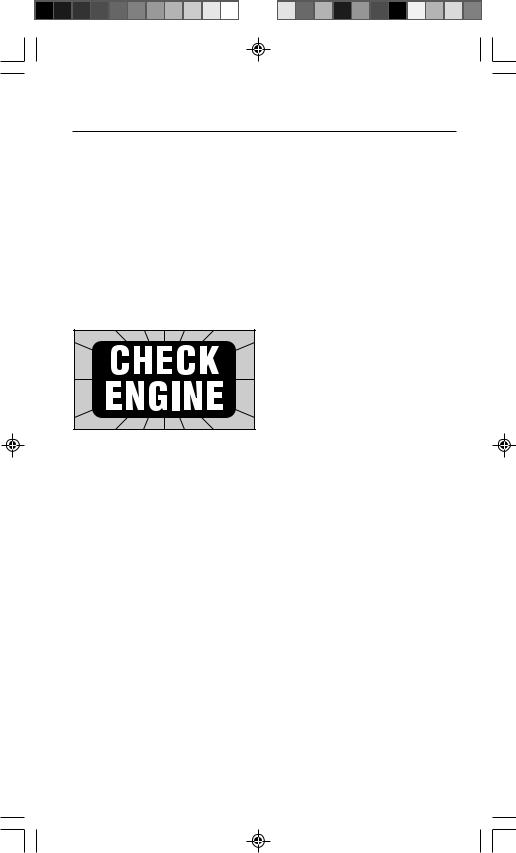
The“CheckEngine”light
The engine computer turns the “Check Engine” light on and off as needed.
This dashboard message light is either amber or red and labeled:
–“Check Engine” or,
–“Service Engine Soon” or,
–“Service Engine Now” or,
–marked with a small engine picture.
“CheckEngine”light:Normal Operation
The “Check Engine” light is normally OFF when the engine is RUNNING.
NOTE: The light will come on when ignition key is in ON position, but the engine is OFF. (For example, before you start the engine.) This is a normal test of all the dashboard message lights.
If the “Check Engine” light does not come on, you have an electrical problem which needs repair. Refer to the “Diagnostic Circuit Check” steps in the “Basic Diagnostic Procedures” section of your vehicle service manual. (Manual sources listed on page 4.)
“CheckEngine”Light:Problem Spotted!
Light ON and stays ON (when the engine is RUNNING)
–The computer sees a problem that does not go away. (A “hard” failure.)
–The light will stay on as long as the problem is present.
–A trouble code is stored in computer memory. (A “hard” code.)
–Use the Code Scanner at the earliest convenient time to obtain codes. Refer to section 3, “Reading Codes”.
“CheckEngine”Light:Intermittent Problem!
Light ON and then goes OFF (when the engine is RUNNING)
–The computer saw a problem, but the problem went away. (An “intermittent” failure.)
–A trouble code is stored in computer memory. (An “intermittent” code.)
–The light went out because the problem went away, but the code stays in memory.
–Use the Code Scanner at the earliest convenient time to obtain codes. Refer to Section 3, “Reading Codes”.
NOTE: The computer will automatically erase codes after several restarts (typically 50) if the problem does not return.
APoorlyRunningEngine(No “CheckEngine”light)
Most likely this condition is not due to computer system failures - but reading codes can still be useful as part of a basic troubleshooting procedure. Review Section 4, “Using Codes” before proceeding to Section 3, “Reading Codes”.
7
ReadingCodes
Using the Code Scanner to Read Codes
1)Safety First!
•Set the parking brake.
•Put shift lever in PARK (automatic transmission) or NEUTRAL (manual transmission).
•Block the drive wheels.
•Make sure ignition key is in OFF position.
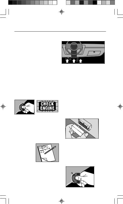
2)Test the “Check Engine” Light
(Also called “Service Engine Soon”, “Service Engine Now” or labeled with a small engine picture.)
•Turn ignition key from OFF to ON position, but do not start the engine.
•Verify that the light turns on.
ON
F
F

O
•If the light does not turn on, you have a problem with this circuit which must be repaired before proceeding. Refer to the “Diagnostic Circuit Check” procedure in
your vehicle service manual. (See manual listings on page 4.)
•Turn ignition key OFF.
3)Have a Pencil 
 and Paper
Ready
This is for 
 writing down
all the codes.
4)Find the Computer Test Connector
•Service manuals call this connector the Assembly Line Diagnostic Link (ALDL) connector. It may also be called the Assembly Line Communication Link (ALCL) or
simply test connector.
•The connecter is located under the dashboard on the driver’s side.
Exceptions:
–LeMans: Located behind passenger side kick panel. Remove snapon cover for access.
–Fiero: Located in the center console behind cover panel.
–Corvette: Sometimes located in centerconsole behind ashtray. Consult service manual for exact location.
•The connector may be in full view, or it may be recessed behind a panel. An opening in the panel allows access to recessed connectors.
•The connector may have a slip-on cover labeled “Diagnostic Connector.” Remove cover for testing. Replace cover after testing. Some vehicles require this cover in place for proper operation.
5)Verify Ignition Key is OFF
|
F |
O |
F |
||
O |
|
|
|
N |
|
|
|
|
8
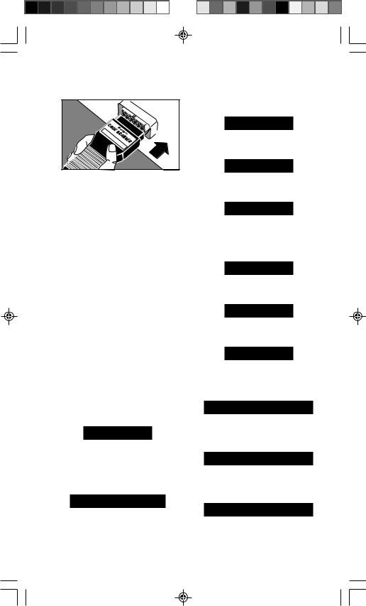
6)Plug the Code Scanner into the Test Connector. Put TEST switch on ENGINE.
Car |
|
|
|
|
GM |
1982Computer |
|
|
|
|
|
|
|
|
|
& |
Code |
|
|
|
higher |
Reader |
||
|
- |
|
||
|
|
CP |
|
|
|
|
|
9001 |
|
•The Code Scanner only fits ONE WAY into the test connector.
•The Code Scanner will not harm the vehicle engine computer.
NOTE: The Code Scanner does not use all of the test connector contacts. Also, one Code Scanner pin may plug into an empty test connector position. This is normal.
7)Turn Ignition Key to ON Position but DO NOT START THE ENGINE
You may hear some clicking sounds coming from under the hood. This is normal.
WARNING: Stay away from the radiator cooling fan! It may turn on.
8)Get Codes from the Flashing “Check Engine” Light
NOTE: If the light does not flash, you have a problem which must be repaired before proceeding. Refer to “Diagnostic Circuit Check” chart in vehicle service manual.
Count flashes to get trouble codes.
Code 12 looks like:
PAUSE
FLASH (pause) FLASH FLASH
(FLASH = 1, FLASH FLASH = 2.
Put 1 and 2 together = code 12.)
Code 23 looks like:
PAUSE
FLASH FLASH (pause)
FLASH FLASH FLASH
•Each code is flashed three (3) times before the next trouble code is sent.
•After all codes are sent, the whole
sequence is repeated. This continues until the ignition key is turned OFF (so you can double check your code list).
Example of code 12 only:
PAUSE
FLASH (pause) FLASH FLASH
(longer pause)
PAUSE
FLASH (pause) FLASH FLASH
(longer pause)
PAUSE
FLASH (pause) FLASH FLASH (even longer pause, then start over again)
Example of code series 12 and 24:
PAUSE
FLASH (pause) FLASH FLASH
(longer pause)
PAUSE
FLASH (pause) FLASH FLASH
(longer pause)
PAUSE
FLASH (pause) FLASH FLASH
even longer pause, then go to next code)
PAUSE
FLASH FLASH (pause)
FLASH FLASH FLASH FLASH
(longer pause)
PAUSE
FLASH FLASH (pause)
FLASH FLASH FLASH FLASH
(longer pause)
PAUSE
FLASH FLASH (pause)
FLASH FLASH FLASH FLASH
(even longer pause, then start all over from the very beginning)
9

•A code 12 is always sent even when the computer sees no problem. This tells you the computer diagnostic checks are working properly. If you do not get
a code 12, or if the “Check Engine” light does not flash you have a problem which must be repaired. Refer to “Diagnostic Circuit Check” procedure in vehicle service manual. (See manual listing on page 4.)
•All codes are two (2) digits long.
•Codes are sent in numeric order from the lowest number to the highest.
TransmissionCodes:
The engine computer can send trouble codes for transmission problems - if the vehicle has a computer controlled transmission.
NOTE: Some diesel powered trucks have a computer controlled transmission. These vehicles will only send transmission related codes since the the diesel itself is not computer controlled.
•GM Vehicles
–The “Check Engine” light flashes both engine codes and transmission codes.
•Saturn Vehicles
–The “Check Engine” light flashes engine codes.
–The “Shift to D2” light flashes transmission codes.
Look for a code 11 flashed on the “Check Engine” light. This is a signal telling you transmission codes will then be flashed on the “Shift to D2” light. Transmission codes are flashed in a way similar to engine codes.
9) Turn Ignition Key OFF
10)Remove Code Scanner and Reinstall Connector Cover, if supplied.
The computer system is now back to normal operation.
11)Refer to “Test Results” chart on page 9
This completes the code reading procedure.
At this point you can either:
•Have your vehicle professionally serviced. Trouble codes indicate problems found by the computer.
or,
•Repair the vehicle yourself using trouble codes to help pinpoint the problem.
10
TEST RESULTS |
COMMENTS |
|
No indication on |
• You have a problem which needs repair |
|
“Check Engine” |
before using the Code Scanner. |
|
light |
||
• Refer to “Diagnostic Circuit Check” chart |
||
or, |
||
in vehicle service manual. |
||
Did not receive |
||
|
||
Code 12. |
|
|
|
|
|
Code 12 only. |
• Computer did NOT find a problem. |
|
|
• If a driveability problem persists, perform |
|
|
“Visual Inspection” and “Basic Mechanical |
|
|
Checks” (Section 4, “Using Codes”.) |
|
|
• Refer to “Diagnosis by Symptom” charts in |
|
|
vehicle service manual. (Additional |
|
|
electrical and mechanical checks are |
|
|
listed.) |
|
|
|
|
Received Code 12 |
• Computer found problems in vehicle. |
|
along with other |
• Follow steps in Section 4, “Using Codes”. |
|
codes. |
• Code definitions are in Section 5, “Code |
|
|
||
|
Meanings”. |
|
|
– GM engine and transmission codes start |
|
|
on page 14. |
|
|
– Saturn engine codes start on page 14. |
|
|
• Saturn vehicles only: Code 11 means |
|
|
transmission codes are flashed on “Shift |
|
|
to D2” light. |
|
|
– Saturn transmission codes start on |
|
|
page 19. |
|
|
|
11

UsingCodes
Using Trouble Codes as Part of a Basic
Troubleshooting Procedure
A driveability problem can have many possible causes which are not related to the computer system. Reading codes is one part of a good troubleshooting procedure consisting of:
1)Visual Inspection
2)Basic Mechanical Checks
3)Reading Codes
4)Using the Vehicle Service Manual
5)Erasing Codes
1) VisualInspection
Doing a thorough visual and “handson” underhood inspection before starting any diagnostic procedure is essential!
You can find the cause of many drivability problems by just looking, thereby saving yourself a lot of time.
•Are routine maintenance items O.K.?
–Clean air filter
–Correct fluid levels
–Recommended tire pressure
–Good ignition system components - spark plugs, wires and the like.
•Has the vehicle been serviced recently?
–Sometimes things get reconnected in the wrong place, or not at all.
•Don’t take shortcuts.
–Inspect hoses and wiring which may be difficult to see because of location beneath air cleaner housings, alternators and similar components.
•Inspect all vacuum hoses for:
–Correct routing. (Hoses may be missing or misconnected.) Refer to vehicle service manual, or Vehicle Emission Control
Information |
YST |
|
CRUISE |
|
|
|
HVAC |
(VECI) |
CE BOOSTER |
|
|
|
VAC |
BRAKE BOOSTER |
|
|
G GAP |
EGR |
|
decal |
REG |
|
|
|
REG. |
TO TRANS |
|
|
|
FUEL |
|
|
U.S.A. |
PRESS |
|
located in |
EGR |
MODE |
|
EM |
VAC |
|
|
|
REG |
|
|
the engine |
|
FRONT |
|
|
OF CAR |
||
compart- |
|
|
|
ment. |
|
|
|
–Pinches and kinks.
–Splits, cuts or breaks.
•Inspect wiring for:
–Contact with sharp
edges.
(This happens often.)
–Contact with hot
surfaces, such as exhaust manifolds.
–Pinched, burned or chafed insulation.
–Proper routing and connections.
• |
Check |
|
electrical |
|
connectors |
|
for: |
|
–Corrosion |
|
on pins. |
|
–Bent or |
|
damaged pins. |
–Contacts not properly seated in housing.
–Bad wire crimps to terminals.
Problems with connectors are common in the engine control system. Inspect carefully. Note that some connectors use a special grease on the contacts to prevent corrosion. Do not wipe off! Obtain extra grease, if needed, from your vehicle dealer. It is a special type for this purpose.
12
2) BasicMechanicalChecks
Don’t overlook the basic checks listed on the next page. Mechanical problems by themselves can always create engine troubles. Even worse, these problems can make a good sensor send an incorrect signal to the computer. Then the computer runs the engine improperly or sets a trouble code.
• Cylinder compression:
–Check for proper |
120 |
150 |
180 |
|
|
compression in |
6 |
|
12 |
15 |
|
|
90 |
9 |
|
210 |
|
each cylinder. |
60 |
TESTER 21 |
240 |
||
30 |
|
||||
|
3 |
|
|
18 |
|
|
COMPRESSION |
270 |
|||
|
|
|
|
|
300 |
–Refer to vehicle service manual for specifications.
• Exhaust backpressure:
–Check for any restrictions in the exhaust system.
• Ignition timing (If adjustable):
–Verify timing is within specifica-
tion. |
INDUCTIVE TIMING LIGHT |
–Refer to vehicle service manual, or Vehicle Emission Control Information (VECI) decal
located in the
engine compartment.
–Be sure to disable computer spark advance timing circuit, if used, when checking basic timing!
• Air induction system:
–Check for intake manifold vacuum leaks.
–Check for carbon or varnish
build-up on throttle valve or idle speed control device.
3)ReadCodes
Refer to Section 3, “Reading Codes”. Remember there are two types of codes:
•“Hard” codes – codes for problems which are present now.
•“Intermittent” codes – codes for problems which happened in the past, but are not happening now.
Remember...
–“Check Engine” light ON: You have at least one “hard” code stored in memory. (You may have more “hard” or “intermittent” codes stored, also.)
–“Check Engine” light OFF: Stored codes are for “intermittent” problems. (Exception: sometimes there are minor “hard” faults which do not turn on the “Check Engine” light.)
How to Tell “Hard” Codes from “Intermittent” Codes
Do the following if you are not sure:
•Write down all codes (except code 12). For example: 15, 34.
•Erase codes from computer memory. (Refer to Step 5.)
•Drive vehicle for at least 10 minutes at normal temperature, cruise speed and load. (The computer may want to verify a fault for several minutes before storing a code.)
•Read codes again. Codes which return are “hard” faults. Codes which do not return are “intermittent” faults. For example, if you see code 15 (but not 34) then you know code 15 is a “hard” code and code 34 was “intermittent”.
You troubleshoot the “hard” problems differently from the “intermittent” ones.
4)UseVehicleServiceManual
Dealing with “Hard” Codes
• Refer to
the vehicle service manual diagnostic code
charts.
These will be in Section 6E in the GM manual. Other publications have this information in books or sections
13
called “Computerized Engine Controls”, “Electronic Engine Controls” or “Tune-Up Information.”
•Follow all the steps in the diagnostic procedure for the trouble code.
•Be sure to erase the trouble codes from computer memory after completing repair work. (See Step 5, “Erasing Codes from Computer Memory”.)
•Drive vehicle for at least 10 minutes at normal temperature, cruise speed and load.
–Read codes again to verify trouble code is gone (problem fixed). Other codes may have been repaired at the same time!
Dealing with “Intermittent” Codes
These codes are for problems which happened in the past, but are not present now.
•Usually these problems are due to loose connections or bad wiring. The problem cause can often be found with a thorough visual and “hands-on” inspection. (Refer to Step 1, “Visual Inspection”.)
•Refer to the vehicle service manual diagnostic code section. You can not use the code chart procedures because they are for “hard” problems - those which are present now. However, the charts have suggestions for dealing with intermittents and can tell you where bad connections, etc., might exist. You can also refer to the “Diagnosis by Symptom” charts.
•Be sure to erase the trouble codes from computer memory after completing repair work. (See Step 5, “Erasing Codes from Computer Memory”.)
•Drive vehicle for at least 10 minutes at normal temperature, cruise speed and load.
–Read codes again to verify trouble code is gone (problem fixed). Other codes may have been repaired at the same time!
Dealing with No Trouble Codes
Have a driveability problem, but only get code 12? Make sure you do Step 1, “Visual Inspection” and Step 2, “Basic Mechanical Checks”. If you did not find the problem, then refer to “Diagnosis by Symptom” charts in vehicle service manual.
5)ErasingCodesfromComputer Memory
Erase codes from memory whenever you complete a repair or to see if a problem will occur again. Note: The computer will automatically erase codes after several restarts (typically 50) if the problem does not return.
GM
Proceed as follows:
• Observe all safety precautions. (See |
|||||
|
page 2.) |
|
|
|
|
• Turn ignition key ON. |
|
|
|
|
|
• |
Insert Code |
|
|
|
|
|
Scanner. |
|
|
|
|
|
Make sure |
GM |
1982 mputer |
|
|
|
|
Car |
|
|
|
|
|
|
Co |
|
|
|
TEST switch |
|
& Co |
Rea |
|
|
|
higher - |
|||
|
|
de |
|
||
|
|
CP |
9001 |
der |
|
|
is in ENGINE |
|
|
|
|
• |
position! |
|
|
|
|
Turn ignition key |
|
ABS |
|
ENGINE |
|
|
|
|
T E S T |
||
|
OFF. |
|
|
|
|
• |
Remove the |
|
|
|
|
|
ECM fuse |
|
|
|
|
|
from the |
|
|
|
|
|
fuse block |
|
|
|
|
|
for 10 |
|
|
|
|
|
seconds. |
|
|
|
|
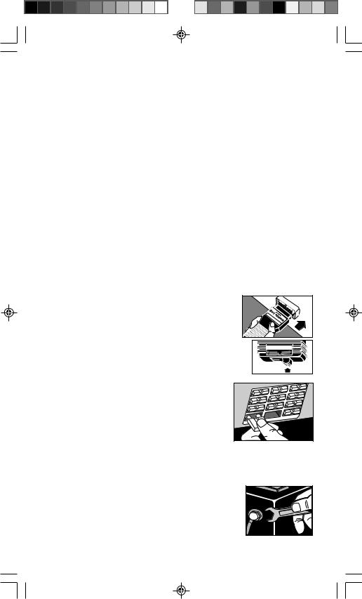
• Replace
fuse.
•Remove
Code Scanner.
If ECM fuse cannot be located, then –
•Disconnect power to the computer. To do this:
–Disconnect the positive battery terminal “pigtail”,
OR
14
–Open the in-line fuse holder going to the positive battery terminal, OR
–Disconnect negative battery terminal – but this will also erase other items too, such as digital clock settings and preset digital radio tuning.
•All the trouble codes are now erased from computer memory!
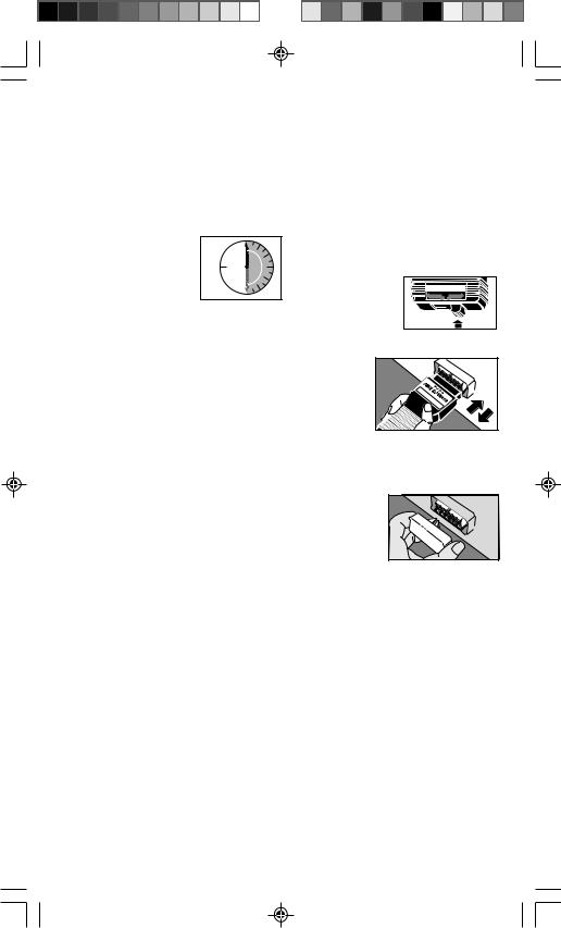
• |
Wait thirty (30) |
30 |
|
seconds. |
|
• |
Reconnect power |
SECONDS |
|
||
|
to the computer. |
|
IMPORTANT: The
computer has a “learning” ability to take care of minor variations in engine control operation. Whenever you erase the computer memory by disconnecting power, the computer has to “relearn” various things. Vehicle performance may be noticeably different until it “relearns.” This temporary situation is normal. The “learning” process takes place during warm engine driving.
SATURN
Use the GM method, or proceed as follows:
•Observe all safety precautions. (See page 2.)
Warning: Stay away from the engine cooling fan. It may turn on during this procedure.
•Turn ignition key ON, but DO NOT START THE
ENGINE.
• Put TEST switch |
T E S T |
|
ABS |
ENGINE |
|
on ENGINE. |
|
|
•Plug and unplug the Code Scanner
into the test connector
3 times within 5 seconds.
Car |
|
GM |
1982Computer |
|
& |
|
higher |
Code |
Reader |
|
CP |
|
|
- |
9001 |
|
|
||
•All the trouble codes are now erased from computer memory!
•Turn ignition key OFF.
•Remove
Code Scanner and re-install connector cover, if supplied.
NOTE:
•The engine control computer is usually called ECM (Engine Control Module) or PCM (Powertrain Control Module) in the vehicle service manuals.
•Information flags and “Intermittent” codes may not by erased using this procedure. The presence of these codes will not cause any driveability or future self-diagnostics problems.
15
CodeMeanings
Note:
•Code meanings can vary with vehicle, model year, engine type and options.
•If a code number has more than one definition listed, note that that only one definition applies to your vehicle. Consult service manual to get the specific definition and troubleshooting procedure for your vehicle.
•Follow vehicle service manual procedures to find the cause of the code.
Remember:
1)Visual inspections are important!
2)Problems with wiring and connectors are common, especially for intermittent faults.
3)Mechanical problems (vacuum leaks, binding or sticking linkages, etc.) can make a good sensor send an incorrect signal to the computer. This can cause a Trouble Code.
4)Incorrect information from a sensor may cause the computer to control the engine in the wrong way. Faulty engine operation could even make a different good sensor
send an incorrect signal to the computer and generate more trouble codes!
Codelists:
This page: (Codes from flashing “Check Engine” light.)
•GM engine codes
•GM electronic transmission codes
•Saturn engine codes
Page 19 (Codes from flashing “Shift to D2” light.)
•Saturn electronic transmission codes
Refer to Section 4, “Using Codes” for troubleshooting tips and steps to erase codes from computer memory.
GM/Saturn Engine Codes, GM Transmission Codes
(Saturn transmission code list begins on page 19)
11
Transaxle codes present (Saturn).
Whenever code 11 is sent, it means transmission codes will be flashed next on the “Shift to D2” light. Refer to page 19 for Saturn transmission code list.
12
Diagnostic test is working properly. (Engine computer verifies no RPM Reference Pulses are present during engine off testing.)
13
Oxygen (O2) sensor - signal stays low (“lean”) during warm engine cruise or sensor circuit is open or left sensor circuit is open (dual sensor models).
14
Coolant temperature sensor (CTS) - signal voltage is low.
15
Coolant temperature sensor (CTS) - signal voltage is high.
16
Battery or alternator problem - voltage too high or low.
OR
Direct ignition system (DIS) fault - line open or shorted to ground.
OR
Ignition system fault - Loss of 2X or Low Resolution Pulse signal.
OR
Transmission speed error.
17
RPM signal problem.
OR
Camshaft sensor - circuit problems.
OR
Electronic Control Module (ECM) computer circuit problem - Pull-up resistor (Saturn).
18
Camshaft or Crankshaft sensor - circuit problems.
OR
Fuel Injector circuit is not working properly - possible blown fuel injector fuse.
19
Ignition system fault - Intermittent 7X signal or loss of 58X signal or 6X signal (Saturn).
16

21
Throttle position sensor (TPS) - signal voltage is high during engine idle or deceleration.
22
Throttle position sensor (TPS) - signal voltage is low during engine idle.
OR
Fuel cutoff relay circuit - open or shorted to ground.
23
Manifold air temperature (MAT) sensor - signal voltage is low or high.
OR
Throttle position sensor (TPS) error.
OR
Mixture Control (M/C) solenoid - open or short circuit problems.
24
Vehicle speed sensor (VSS) - open or short circuit problems.
25
Manifold air temperature (MAT) sensor - signal voltage is low.
OR
Vacuum switching valve circuit - open or shorted to ground.
OR
ATS sensor - signal voltage is high.
26
Quad-Driver module or Quad-driver No. 1 error.
27
2nd gear switch.
OR
Quad-Driver module or Quad-driver No. 2 error.
28
3rd gear switch.
OR
Quad-Driver module or Quad-driver No. 3 error (Corvette).
OR
(Transmission) Fluid pressure switch assembly - open or short circuit problems.
29
4th gear switch.
OR
Quad-Driver module or Quad-driver No. 3 error.
OR
Secondary air injection system - circuit problems.
31
Manifold absolute pressure (MAP) sensor - signal voltage is low.
OR
Fuel injector.
OR
Park/Neutral switch - circuit problems.
OR
CAM sensor - circuit problems.
OR
Engine speed control governor malfunction. (Van)
OR
Turbocharger wastegate overboost.
OR
Wastegate electrical signal - open or shorted to ground.
OR
Purge solenoid voltage high (carburetor engines)
32
Barometric pressure (BARO) sensor circuit failure.
OR
Exhaust gas recirculation (EGR) valve diagnostic switch - closed during engine start-up or open when EGR flow requested by ECM.
OR
EGR/EVRV.
33
Mass air flow (MAF) sensor - signal voltage or frequency is high during engine idle.
OR
Manifold absolute pressure (MAP) sensor - signal voltage is high during engine idle. (Note: Engine mis-fire or unstable idle may cause this code.)
34
Mass air flow (MAF) sensor - signal voltage or frequency is low during engine cruise.
OR
Manifold absolute pressure (MAP) sensor - signal voltage is low during ignition on.
OR
Pressure sensor circuit - signal voltage too high or low (carburetor engines).
35
Idle air control (IAC) system problem - can not set desired RPM.
36
Mass air flow (MAF) sensor - burn-off circuit problem.
OR
Transmission shift problem (electronically controlled transmissions only).
OR
Direct ignition system (DIS) fault - loss of 24X signal or extra or missing pulses in electronic spark timing (EST) signal.
OR
Ignition system fault - loss of High Resolution Pulse signal.
37
Brake switch stuck “on”.
38
Brake switch circuit fault.
OR
Knock sensor (KS) - open circuit problem.
39
Torque converter clutch (TCC) circuit fault.
OR
Clutch switch circuit problems.
OR
Knock sensor (KS) - short circuit problem.
17

41
Cam sensor (CAM) failure.
OR
Cylinder select error.
OR
Tach input error - no reference pulses during engine run.
OR
Electronic spark timing (EST) circuit - open or shorted to ground during engine run.
OR
Direct ignition system (DIS) fault - bypass circuit open or shorted to ground during engine run.
OR
Ignition system fault - loss of 1X Reference Pulse signal.
42
Electronic spark timing (EST) circuit - open or shorted to ground during engine run.
OR
Direct ignition system (DIS) fault - bypass circuit open or shorted to ground during engine run.
OR
Fuel cutoff relay circuit - open or shorted to ground.
43
Electronic spark timing (EST) circuit - low voltage detected.
OR
Electronic spark control (ESC) - circuit problems.
44
Lean exhaust indication - oxygen (O2) sensor voltage stays low after one or two minutes of engine run. (Left sensor on dual sensor engines.)
45
Rich exhaust indication - oxygen (O2) sensor voltage stays high after one minute of engine run. (Left sensor on dual sensor engines.)
46
Vehicle anti-theft system (VATS) failure.
OR
Power steering pressure switch failure.
47
Electronic control module (ECM) computer circuit problems - universal asynchronous receiver/ transmitter (UART) link or data loss.
OR
Knock sensor module located in the computer is not working properly.
48
Misfire symptom.
OR
Mass air flow (MAF) sensor - open or short circuit MAF sensor signal.
49
High idle RPM or vacuum leak (Saturn).
51
Electronic control module (ECM) computer circuit problems - faulty programmable read-only memory (PROM), MEMCAL, ECM or checksum errors.
52
Electronic control module (ECM) computer circuit problems - faulty or missing CALPAC or MEM-CAL, analog to digital converter (A/D) error or Quad-Driver module (QDM) fault.
OR
Oil temperature sensor - signal voltage is low (Corvette).
OR
System voltage high for a long period of time. (Electronic transmission note: this fault may cause other codes to be set.)
53
Over voltage condition. (Electronic transmission note: this fault may cause other codes to be set.)
OR
Exhaust gas recirculation (EGR) - system problems or EGR Solenoid No.1 problem.
OR
Voltage reference error. OR
Vehicle anti-theft system (VATS) problems.
54
Low fuel pump voltage.
OR
Fuel pump relay.
OR
EGR Solenoid No. 2 failure.
OR
Quad-Driver module (QDM) output failure.
OR
Mixture Control (M/C) solenoid - circuit voltage too high.
55
Electronic control module (ECM) computer circuit problems - ECM failure, serial bus error, SAD error or fuel lean malfunction.
OR
EGR Solenoid No. 3 failure.
56
Corrosivity/add coolant.
OR
Port throttle system vacuum sensor problems.
OR
Quad-Driver “B” fault.
57
Boost Control problem.
58
Vehicle anti-theft system (VATS) problem.
OR
Transmission Temperature Sensor (TTS) - short circuit problem in sensor or wiring.
OR
Transmission fluid temperature high.
59
Transmission Temperature Sensor (TTS) - open circuit problem in sensor, connector or wiring.
OR
Transmission fluid temperature low.
18
61
Oxygen (O2) sensor degraded.
OR
Port throttle system error.
OR
Cruise control problems - vent solenoid circuit.
OR
Air Conditioner (A/C) system performance problems.
62
Gear switch circuit problems.
OR
Oil temperature sensor - signal voltage is high (Corvette).
OR
Cruise control problems - vacuum solenoid circuit.
63
Manifold absolute pressure (MAP) sensor - signal voltage is high.
OR
Small EGR failure.
OR
Right oxygen (O2) sensor failure (dual sensor engines).
OR
Cruise control system problem.
64
Manifold absolute pressure (MAP) sensor - signal voltage is low.
OR
Medium EGR failure.
OR
Right oxygen(O2) sensor - lean condition indicated (dual sensor engines).
65
Large EGR failure.
OR
Fuel injector current low.
OR
Right oxygen (O2) sensor - rich condition indicated (dual sensor engines).
OR
Cruise control position sensor problem.
66
Air Conditioner (A/C) pressure sensor - circuit problems or low A/C charge.
OR
Electronic Control Module (ECM) computer circuit problem - internal reset occurred.
OR
(Transmission) 3-2 shift control solenoid - circuit problems.
67
Cruise control - switch circuit problems.
OR
Air Conditioner (A/C) pressure sensor - circuit problems.
OR
Torque Converter Clutch (TCC) solenoid - circuit problems.
OR
Cruise control switches - circuit problems.
68
Cruise control - system circuit problems.
OR
Air Conditioner (A/C) clutch relay - short circuit.
OR
(Transmission) Overdrive ratio error - engine RPM greater than input speed.
69
Air Conditioner (A/C) system - pressure switch or A/C clutch relay circuit problems.
OR
Torque converter clutch stuck “on”.
70
Air Conditioner (A/C) pressure sensor - signal voltage too high.
71
Air Conditioner (A/C) evaporator temperature sensor - signal voltage too low.
72
Gear Select switch - circuit problems.
OR
Vehicle Speed Sensor (VSS) - loss of signal.
73
Air Conditioner (A/C) evaporator temperature sensor - signal voltage too high.
OR
(Transmission) Pressure control solenoid - circuit problems.
74
Traction control circuit voltage low.
75
Exhaust gas recirculation (EGR) system - Solenoid No.1 problem.
OR
System voltage low - charging system problems.
OR
Transmission voltage low - low system voltage possibly caused by generator voltage supply circuit or power train control module (PCM).
76
Exhaust gas recirculation (EGR) system - Solenoid No.2 problem.
77
Exhaust gas recirculation (EGR) system - Solenoid No.3 problem.
OR
Primary cooling fan relay driver circuit - circuit problems.
78
Secondary cooling fan relay driver circuit - circuit problems.
79
Vehicle Speed Sensor (VSS) - signal voltage too high.
OR
Transmission Temperature Sensor (TTS) - high temperature indicated.
80
Vehicle Speed Sensor (VSS) - signal voltage too low.
19

81
Brake switch circuit problems.
OR
Anti-Lock Brake System (ABS) message fault (Saturn).
OR
(Transmission) Solenoid “B” (3-2 shift solenoid) - open or short circuit problems.
82
Ignition system fault - 3X signal problem.
OR
Electronic control module (ECM) computer circuit problem - internal communications failure (Saturn).
OR
(Transmission) Solenoid “A” (1-2 shift solenoid) - open or short circuit problems.
83
Torque Converter Clutch (TCC) solenoid - circuit problems.
OR
Reverse Inhibit - open or short circuit in reverse inhibit solenoid coil.
84
3-2 Control solenoid - open or short circuit problems.
OR
Skip shift solenoid - open or short circuit problems.
85
Electronic control module (ECM) computer circuit problems - faulty programmable read-only memory (PROM).
OR
(Transmission) Input or output speed sensor - circuit problems. (Speed sensor signals do not agree with with selected gear range.)
OR
Torque converter clutch (TCC) - TCC is mechanically stuck on.
86
Electronic control module (ECM) computer circuit problems - faulty analog- to-digital (A/D) converter.
OR
(Transmission) Low gear error - transmission in 3rd or 4th gear when computer commanding 1st or 2nd gear.
87
Electronic control module (ECM) computer circuit problems - faulty electrically erasable programmable read-only memory (EEPROM).
OR
(Transmission) High gear error - transmission in 1st or 2nd gear when computer commanding 3rd or 4th gear.
88
Electronic control module (ECM) computer circuit problem - internal reset occurred.
91
Skip shift light - open or short circuit problems in skip shift light circuit.
93
Pressure control solenoid - transmission line pressure not at desired level.
95
Change oil light - wrong voltage is present in light circuit for more than 26 seconds.
96
Transmission voltage low - low system voltage possibly caused by generator voltage supply circuit or power train control module (PCM).
OR
Low oil light - wrong voltage is present in light circuit for more than 26 seconds.
97
Vehicle speed sensor (VSS) - output circuit problems.
99
Tachometer output circuit
problems.
20
Saturn Transmission Codes
(GM/Saturn engine codes and GM transmission code list begins on page 14.)
Note: Code numbers labeled “Information Flag” may be sent along with the regular (unlabeled) trouble codes. The computer sends Information Flags to help you find the cause of a trouble code. Note that conditions which only cause an Information Flag will not turn on the “Check Engine” light. Refer to vehicle service manual troubleshooting charts.
26
Torque converter clutch stuck”on”.
27
(InformationFlag)
Quick quad-driver output fault - open or short circuit on any of the qaud-driver module circuits (QDM) that lasts 5 seconds or longer.
31
Transaxle temperature circuit open.
32
Transaxle temperature circuit grounded.
47
(InformationFlag)
Powertrain Control Module (PCM) computer circuit problem - communication interrupt failure.
48
Hold mode voltage is too low.
OR
(InformationFlag)
Reference input intermittent or noisy - missing or extra ignition reference pulses are detected by powertrain control module (PCM).
13 |
34 |
|
(InformationFlag) |
||
(InformationFlag) |
Powertrain Control Module |
|
Line pressure high. |
(PCM) computer circuit |
|
14 |
problem - communications |
|
failure. |
||
(InformationFlag) |
35 |
|
Line pressure low. |
||
No turbine speed signal. |
||
15 |
||
36 |
||
(InformationFlag) |
||
Turbine speed signal |
||
Hot light. |
||
noise. |
||
|
||
16 |
41 |
|
No 1st gear. |
Vehicle Speed Sensor |
|
OR |
(VSS) circuit - no signal. |
|
(InformationFlag) |
42 |
|
Electrical variable orifice |
||
Vehicle Speed Sensor |
||
(EVO) fault. |
||
(VSS) circuit - signal noise. |
||
|
||
18 |
43 |
|
(InformationFlag) |
||
(InformationFlag) |
||
No gears available. |
||
Master relay - open or |
||
|
||
21 |
grounded. |
|
2nd gear stuck “on”. |
44 |
|
|
||
22 |
(InformationFlag) |
|
No 2nd gear. |
Master relay - shorted. |
49
(InformationFlag)
Gear selector error signal.
51
(InformationFlag)
Powertrain Control Module (PCM) computer circuit problem - serial link data invalid.
52
Hold mode stuck “on”.
OR
(InformationFlag)
Battery voltage out of range - battery voltage has dropped below 11 volts or has increased above 17 volts.
53
Hold mode stuck “off”.
OR
(InformationFlag)
ESC (Knock present) - powertrain control module (PCM) can not reduce engine knock by retarding timing.
23 |
45 |
|
No 3rd gear. |
(InformationFlag) |
|
24 |
Gear selector switch circuit |
|
problem - no signal. |
||
No 4th gear. |
46 |
|
25 |
||
(InformationFlag) |
||
No torque converter clutch. |
Gear selector switch circuit |
|
|
problem - invalid signal. |
54
Powertrain Control Module (PCM) computer circuit problem - analog to digital (A/D) converter error.
OR
(InformationFlag)
5-volt reference ground - flag will set if manifold
21

absolute pressure (MAP) sensor signal, handwheel sensor signal, throttle position sensor (TPS) signal are zero volts.
55
Transaxle temperature sensor failure.
56
(InformationFlag)
Generic Field-Effect Transistor (FET) driver failure.
57
(InformationFlag)
Powertrain Control Module (PCM) computer circuit problem - non volatile Random Access Memory (RAM) failure.
58
(InformationFlag)
Battery voltage unstable - battery voltage changes more than 3 volts instantaneously.
61
(InformationFlag)
Powertrain Control Module (PCM) computer circuit problem - Programmable Read-Only Memory (PROM) failure.
OR
(InformationFlag)
6X Signal fault - 6X pulses do not occur between each reference pulse or a 6X pulse does not immediately follow a reference pulse. Possible open or intermittent in DIS module harness.
62
(InformationFlag)
Powertrain Control Module (PCM) computer circuit problem - interrupt failure.
63
(InformationFlag)
Powertrain Control Module (PCM) computer circuit problem - Random Access Memory (RAM) failure.
OR
(InformationFlag)
Option check sum error - flag will be set if tire size and options do not compare with those stored in the powertrain control module (PCM).
64
(InformationFlag)
Powertrain Control Module (PCM) computer circuit problem - Electrically Erasable Programmable Read-Only Memory (EE PROM) failure.
65
(InformationFlag)
Ignition voltage problem - too high or low.
66
(InformationFlag)
Clamp shorted.
67
(InformationFlag)
Clamp open.
OR
(InformationFlag)
Handwheel sensor circuit fault - handwheel sensor output voltage is out of tolerance.
68
(InformationFlag)
Line circuit grounded or open.
69
(InformationFlag)
Line circuit shorted.
71
(InformationFlag)
2nd line circuit - grounded or open.
OR
(InformationFlag)
Cooling system high temperature - engine coolant temperature is greater than 239°F (118°C).
72
(InformationFlag)
2nd line circuit - shorted.
OR
(InformationFlag)
Cooling system low temperature - engine coolant temperature is less than 32°F (0°C).
73
(InformationFlag)
3rd line circuit - grounded or open.
OR
(InformationFlag)
Coolant sensor signal unstable - coolant temperature sensor (CTS) indicates a change of more than 59°F (15°C) instantaneously.
74
(InformationFlag)
3rd line circuit - shorted.
OR
(InformationFlag)
Coolant/Transmission temperature sensor ratio error - indicates a degrading coolant temperature sensor (CTS) if transmission temperature sensor (TTS) is working properly.
75
(InformationFlag)
3rd gear stuck “on”.
OR
(InformationFlag)
Air temperature sensor signal unstable - air temperature sensor (ATS) indicates a change of more than 59°F (15°C) instantaneously.
22

76
(InformationFlag)
4th line circuit - grounded or open.
OR
(InformationFlag)
Throttle position sensor (TPS) to manifold absolute pressure (MAP) sensor voltage out of range - flag is set if TPS and MAP voltage readings dont agree with internal relational tables stored in the powertrain control module (PCM).
77
(InformationFlag)
4th line circuit - shorted.
78
(InformationFlag)
4th gear stuck “on”.
79
(InformationFlag)
Torque Converter Clutch (TCC) circuit - grounded or open.
81
(InformationFlag)
Torque Converter Clutch (TCC) circuit - shorted.
82
(InformationFlag)
Transaxle temperature unstable.
83
(InformationFlag)
Transaxle temperature low.
OR
(InformationFlag)
Low coolant - coolant switch opens for 20 seconds with engine running.
84
(InformationFlag)
Brake switch stuck open.
85
(InformationFlag)
Brake switch stuck closed.
86
(InformationFlag)
Engine speed invalid.
87
(InformationFlag)
Torque Converter Clutch (TCC) hold circuit - grounded or open.
88
(InformationFlag)
Torque Converter Clutch (TCC) hold circuit - shorted.
89
(InformationFlag)
Master relay stuck “on”.
91
(InformationFlag)
Assembly Line Diagnostic Link (ALDL) - serial communication link interrupt.
92
(InformationFlag)
Clamp circuit - intermittent fault.
93
(InformationFlag)
Torque Converter Clutch (TCC) hold circuit - intermittent fault.
94
(InformationFlag)
Master enable relay circuit - intermittent fault.
95
(InformationFlag)
Line circuit - intermittent fault.
96
(InformationFlag)
Torque Converter Clutch (TCC) circuit - intermittent fault.
97
(InformationFlag)
2nd gear circuit - intermittent fault.
98
(InformationFlag)
3rd gear circuit - intermittent fault.
99
(InformationFlag)
4th gear circuit - intermittent fault.
23
OtherFeatures
Additional Code Scanner Diagnostic Features
This section contains...
Relay and Solenoid Circuit Test: You can switch on most of the computer controlled relay and solenoid circuits - for checking relay operation or making wiring voltage checks.
Field Service Test (Fuel Injected Engines Only): A quick check of the fuel control system to verify proper operation.
Become familiar with Code Scanner use (Section 3) before using the following procedures.
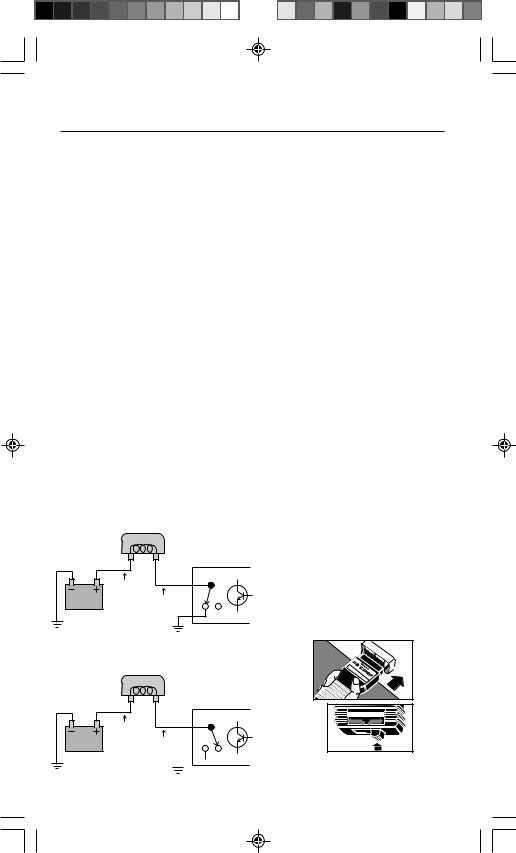
Relay and Solenoid
Circuit Test
Computer controlled relay and solenoid coils are commonly wired as follows:
•One side of the coil is connected to a source of vehicle battery power.
“driver”). The computer energizes the coil by using the transistor switch.
Transistor ON:
–Transistor electrically connects end of coil to circuit ground.
–Coil is ON because circuit is complete. (Coil connected to battery power and ground.)
Transistor OFF:
–Transistor disconnects end of coil from circuit ground.
–Coil is OFF because circuit is open. (Coil not connected to circuit ground.)
You can switch on most of the computer controlled relay and solenoid circuits except the fuel pump relay and fuel injectors. This is helpful for checking relay operation or making wiring voltage checks. Do the following:
•The other side of the coil is wired to the computer.
Inside the computer housing is a transistor switch (often called a
RELAY COIL
COMPUTER
1)Safety First!
•Set the parking brake.
•Put shift lever in PARK (automatic transmission) or NEUTRAL (manual transmission).
•Block the drive wheels.
•Make sure ignition key is in OFF position.
12 volts
or more
Less than 1.5 volts
Transistor ON*
RELAYON
2)Plug the Code Scanner into the Test Connector. Put TEST switch on ENGINE.
*Transistor action is shown using a “switch”
RELAY COIL representation for clarity.
COMPUTER
12 volts
or more
12 volts or more
Car |
|
|
|
|
|
GM |
Co |
|
|
|
|
1982 |
mp |
|
|
||
|
& |
uter |
|
|
|
|
|
Co |
|
|
|
|
|
|
de |
|
|
|
|
|
higher - |
Rea |
|
|
|
|
CP |
9001 |
der |
T E S T |
ABS ENGINE |
 Transistor OFF*
RELAYOFF
24
3) Turn Ignition Key to ON Position but DO NOT START THE ENGINE.
• WARNING: Stay away from the radiator cooling fan! It may turn on.
• Ignore the flashing Check Engine light.
4) Computer Controlled Relays and
Solenoids are Turned ON
Exception: Fuel pump and fuel injectors are OFF. (Refer to vehicle service manual for any other exceptions.)
• Make any relay or |
|
Digital Engine Analyzer |
||||
|
|
|
|
|
|
|
solenoid circuit |
|
|
|
|
|
|
checks at this |
10 Megohm V |
OFF 4 |
|
RPM |
||
|
|
200 |
CYL6 |
|||
|
|
|
750 |
|
X10 |
|
|
|
|
|
CYL |
5 |
|
time. Note the |
V |
20 |
|
|
|
CYL |
|
M |
|
|
|
CYL |
|
|
|
|
|
|
|
8 |
|
|
2 |
|
|
|
CYL |
|
|
20 |
|
|
|
4 |
following special |
|
K |
|
|
8 |
5 |
|
|
|
CYL Dwell |
|||
|
|
2M |
|
|
|
CYL |
|
|
200 |
|
|
|
6 |
circuit actions... |
|
|
20K |
CYL |
|
|
Ohms |
2K |
200 |
|
|
||
– Fuel Injected Engines Only:
The Idle Air
Control (IAC)
motor fully extends (most vehicles) or moves back and forth.
– Carbureted Engines Only: The Idle Speed Control (ISC) motor, if used on vehicle, moves back and forth. Also, the Exhaust Gas Recirculation (EGR) solenoid is energized for 25 seconds.
5) Turn Ignition Key OFF.
• Remove Code Scanner and reinstall connector cover, if supplied.
• The computer system is now back to normal.
• This completes the Relay and Solenoid Circuit Test.
Field Service Test – Fuel
Injected Engines Only
This is a quick check of the fuel control system to verify proper operation - especially after repair work. Service manuals call this the “Field Service Mode”. Do the following:
1)Safety First!
•Set the parking brake.
•Put shift lever in PARK (automatic transmission) or NEUTRAL (manual transmission).
•Block the drive wheels.
•Make sure ignition key is in OFF position.
2)Test the “Check Engine” Light
(Also called “Service Engine
Soon”, “Service Engine Now” or
labeled with a small engine picture.)
• Turn ignition key from OFF to ON |
||||
position, but do not start the |
||||
engine. |
|
|
|
|
• Verify that the light turns on. |
||||
• If the light does not turn on, you |
||||
have a problem with this circuit |
||||
which must be repaired before |
||||
proceeding. Refer to the “Diagnos- |
||||
tic Circuit Check” procedure in your |
||||
vehicle service manual. (See |
||||
manual listings on page 4.) |
||||
3) Start the Engine |
|
|
|
|
WARNING: Always operate vehicle |
||||
in well ventilated area. Exhaust |
||||
gases are very poisonous! |
||||
4) Plug the |
|
|
|
|
Code |
|
|
|
|
Scanner into |
GM arComp |
|
||
|
C |
|
|
|
the Test |
1982 |
& |
uter |
9001 der |
|
CP |
|||
|
|
Co |
Rea |
|
|
|
higher - |
||
|
|
|
de |
|
Connector. |
|
|
|
|
Put TEST |
|
|
|
|
switch on |
|
|
|
|
ENGINE. |
T E S T |
|||
ABS |
ENGINE |
|||
The engine |
|
|
|
|
computer is now |
|
|
|
|
in the “Field |
|
|
|
|
25
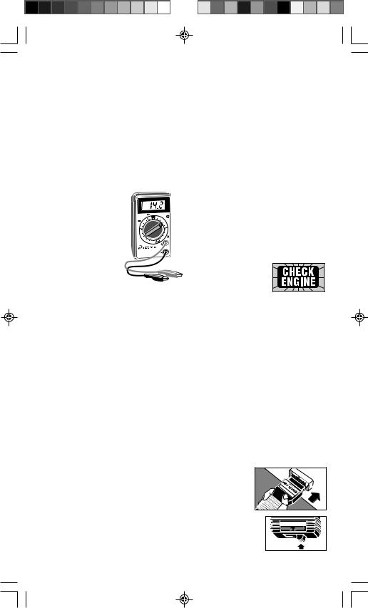
Diagnostic Mode.” The flashing “Check Engine” light shows how the fuel control system is operating.
See below.
Read Section 7, “Computer Basics” or Section 8, “Glossary” for an explanation of Open Loop and Closed Loop operation.
IMPORTANT: The oxygen sensor needs to be hot so the computer can check the signal for proper fuel delivery. Warm the engine by idling for 2 minutes at 2000 RPM. Then, gently rev the engine from idle to part throttle several times. (This creates a changing sensor signal for the computer.) Finally, keep the throttle steady, or at idle, for the rest of the test.
Light flashes 2 times a second
The computer is in
Open Loop operation. The computer will run
“open loop” if it does
not see an oxygen sensor signal because...
–The oxygen sensor is not hot enough to operate (normal condition if engine too cold or sensor cooled down during idle)
or,
–Open circuit problems exist (bad sensor or wiring). Note that this condition will generate a trouble code.
Light flashes once a second
The computer is in
Closed Loop operation. The oxygen sensor is sending a signal.
•Light equally ON and OFF while flashing: system is running correctly (proper air/fuel mixture).
•Light mostly ON while flashing: system is running “rich”.
•Light mostly OFF while flashing: system is running “lean”.
Various mechanical, electronic or wiring problems can cause the computer to sense a “rich” or “lean” running engine. Usually these conditions will generate a trouble code, such as 44 (lean exhaust) or 45 (rich exhaust). Follow vehicle service manual troubleshooting charts to find the cause. The Field Service Test lets you check to see if the problem was fixed. (Light flashing equally ON and OFF once a second.)
Note: While in the “Field Service
Mode”...
– New trouble codes are not stored |
||||
in computer memory. |
|
|
|
|
– On some engines, the computer |
||||
will send a signal for a fixed spark |
||||
advance. |
|
|
|
|
5) Turn Ignition Key OFF |
|
|
|
|
• Remove |
|
|
|
|
Code |
|
|
|
|
Scanner |
GM |
omp |
|
|
|
C |
|
|
|
|
arC |
|
|
|
and re- |
1982 |
uter |
|
|
|
& Co |
|
|
|
|
higher - |
Rea |
||
|
|
9001 |
|
|
|
|
de |
|
|
|
|
CP |
|
der |
install |
|
|
|
|
connector |
|
|
|
|
cover, if |
|
|
|
|
supplied. |
|
|
|
|
• The computer system is now back to normal.
•This completes the Field Service Test.
26

COMPUTERBASICS
What does the Engine Control Computer do?
This section further explains the engine computer control system, the types of sensors and how the computer controls fuel delivery, idle speed and timing.
The following is an introduction to computer controlled engine systems. Additional information may be found in books dealing with this subject available at your local library or auto parts store. The more you know about the computer system, the better and faster you can troubleshoot and fix problems.
WhyComputers?
Computer controls were installed in vehicles to meet Federal Government regulations for lower emissions and better fuel economy. This all began in the early 1980’s when purely mechanical control systems just were not good enough anymore. A computer could be programmed to precisely control the engine under various operating conditions and eliminate some mechanical parts making the engine more reliable.
Note that vehicle service manuals refer to the computer as either the ECM (Engine Control Module) or PCM (Powertrain Control Module).
Whatthecomputercontrols
The main control areas of the computer are:
•Fuel delivery
•Idle speed
•Spark advance timing
•Emission devices (EGR valve, carbon cannister, etc.)
The changes made to the basic engine to allow a computer to control these tasks are the only differences between an older engine and a computerized one. A little later we will discuss just how the computer handles these tasks.
WhathasNOTchanged?
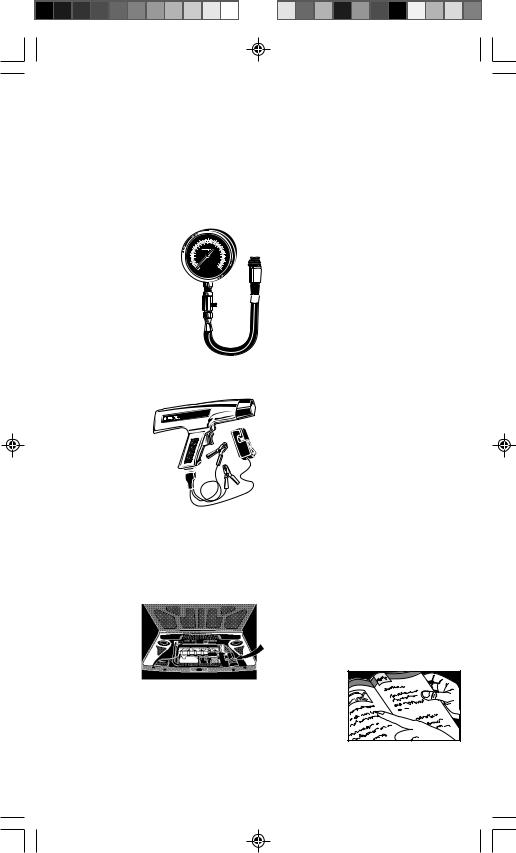
A computer controlled engine is basically the same as earlier types. It is still an internal combustion engine with pistons, spark plugs, valves and cams. The ignition, charging, starting, and exhaust systems are almost the same, as well. You test and repair these systems the same way as before, using familiar tools. The instruction manuals for these tools show you how to perform the tests. Your compression gauge, vacuum pump, dwell-tach meter, engine analyzer, timing light, etc., are still valuable!
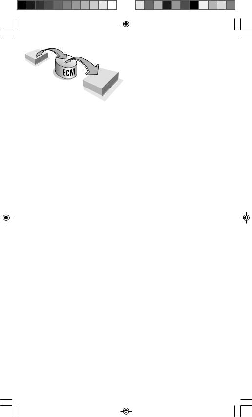
TheEngineComputerControl
System
The computer module is the “heart” of the system. It is sealed in a metal box and linked to the rest of the system by a wiring harness. The computer module is located in the passenger compartment, usually behind the dashboard or front kick panels. This protects the electronics from moisture, extreme temperatures and excess vibration, which are common in the engine compartment.
The computer is permanently programmed by factory engineers. The program is a complex list of instructions telling the computer how to control the engine under various driving conditions. To do its job, the computer needs to know what is happening and then it needs devices to control things.
Sensorsgivethecomputer information
The computer can only work with electrical signals The job of the sensor is to take something the computer needs to know, such as engine temperature, and convert it to an electrical signal which the computer
27
INPUT
SENSORS
BRAINS OF THE
COMPUTER
OUTPUTACTUATORS
can understand.
You can think of sensors as “high tech” senders the devices found in older vehicles for gauges and dashboard message lights (oil pressure, fuel level, etc.) Signals running into the computer are referred to as “inputs.”
Sensors monitor such things as:
•Engine temperature
•Intake manifold vacuum
•Throttle position
•RPM
•Incoming air (temperature, amount)
•Exhaust gas oxygen content
Most engine computer systems will use the sensor types listed above. Additional sensors may be used depending upon the engine, vehicle type or other tasks the computer must do. Note that information from one sensor may be used by the computer for many different tasks. For example, engine temperature is something the computer needs to know when controlling fuel delivery, spark timing, idle speed and emission systems. The sensor information may be very important for one engine control function, but only used to “fine tune” a second one.
Thereareseveraltypesof sensors
•Thermistor – This is a resistor whose resistance changes with temperature. It is used to measure temperatures of coolant or incoming air. It has two wires connected to it.
•Potentiometer – This signals a position, such as throttle position or EGR valve position. It connects to three wires: one for power, one for ground and one to carry the position signal back to the computer.
•Switches – These are either ON
(voltage signal to the computer) or OFF (no voltage signal to the computer). Switches connect to two wires and tell the computer simple things, such as whether or not the air conditioner is running.
•Signal Generator – These create their own signal to tell the computer of some condition, such as exhaust gas oxygen content, camshaft position, or intake manifold vacuum. They may have one, two or three wires connected to them.
Thecomputercontrolsthingswith actuators
The computer can only send out electrical signals (referred to as “outputs”). Devices called actuators are powered by the computer to control things. Actuator types include:
•Solenoids – These are used to control a vacuum signal, bleed air, control fuel flow, etc.
•Relays – These switch high amperage power devices on and off, such as electric fuel pumps or electric cooling fans.
•Motors – Small motors are often used to control idle speed.
Otheroutputsignals
Not all of the computer outgoing signals go to actuators. Sometimes information is sent to electronic modules, such as ignition or trip computer.
Howthecomputercontrolsfuel delivery
Good performance and low emissions depend upon precise fuel control. Early computer controlled vehicles used electronically adjustable carburetors, but fuel injectors were soon introduced.
The job of the computer is to provide the optimum mixture of air and fuel (air/fuel ratio) to the engine for best performance under all operating conditions.
28

The computer needs to know:
•...what the engine operating condition is.
Sensors used: coolant temperature, throttle position, manifold absolute pressure, mass air flow, RPM.
•...how much air is coming into the engine.
Sensors used: mass air flow or a combination of manifold absolute pressure, manifold air temperature, RPM.
•...how much fuel is being delivered.
The computer knows this by how long it turns on the fuel injectors. (The computer uses a “feedback control” or “duty cycle” solenoid on electronic controlled carburetors.)
•...that everything is working the way it should.
Sensor used: exhaust gas oxygen sensor.
Note: Not all engines use every sensor listed above.
Coldenginewarm-upcondition
An example of “Open Loop” opera-
tion...
The coolant temperature sensor tells the computer how warm the engine is. Factory engineers know what the best air/fuel mixture is for the engine at various operating temperatures. (More fuel is needed for a cold engine.) This information is permanently programmed into the computer. After the computer knows the engine temperature, it determines the amount of air coming in, then it will look at its programming to find out how much fuel to deliver and operate the fuel injectors accordingly. (Engines with electronic carburetors don’t do any of this. They have a thermostatically controlled choke just like non-computer engines.)
This process is an example of “Open Loop” operation by the computer. The control system performs an action (expecting a certain result), but has no way of verifying if the desired results were achieved. In this case, the computer operates a fuel injector
expecting a certain amount of fuel to be delivered. (The computer assumes everything in the fuel system is operating as expected.) In open loop operation, the computer has no way of checking the actual amount of fuel delivered. Thus, a faulty fuel injector or incorrect fuel pressure can change the amount of fuel delivered and the computer would not know it.
The computer system is forced to operate “open loop” because no sensor type is available which can measure air/fuel ratios when the engine is cold.
Hotenginecruisecondition
An example of “Closed Loop”
operation...
The computer watches the coolant temperature and throttle position sensors to tell when the engine is all warmed up and cruising. As before, the computer determines the amount of air coming into the engine, then delivers the amount of fuel that should provide the optimum air/fuel mixture. The big difference is that this time the computer uses the oxygen sensor to check how well its doing and re-adjust things, if needed, to make sure the fuel delivery is correct. For example: If the oxygen sensor indicates a “rich” condition, the computer will compensate by reducing fuel delivery until the oxygen sensor signals an optimum air/ fuel ratio. Likewise, the computer will compensate for a “lean” condition by adding fuel until the oxygen sensor once again signals an optimum air/fuel mixture.
This is an example of “Closed Loop” operation. The control system performs an action (expecting a certain result), then checks the results and corrects its actions (if necessary) until the desired results are achieved.
The oxygen sensor only works when it is very hot. During cold engine warmup, and sometimes at idle, the sensor will be too cool to operate (no signal sent). The computer must operate "open loop" during this time because it cannot use the sensor to check the air/ fuel ratio.
29

Acceleration,decelerationandidle conditions
As long as the engine and oxygen sensor are hot, the computer can operate “closed loop” for best economy and least emissions. During the drive conditions listed on the left, the computer may have to ignore the sensor and run “open loop,” relying on internal programming for fuel delivery instructions. During idle, for example, the oxygen sensor may cool down and stop sending a signal. A different situation can occur during wide-open-throttle acceleration. The computer sometimes adds additional fuel (on purpose) for temporary acceleration power. The computer knows it is running “rich” so it ignores the sensor signal until the wide- open-throttle condition is over.
Howthecomputercontrolsidle speed
Throttle position and RPM sensors tell the computer when the vehicle is idling. (Sometimes an idle position switch on the throttle is used.) The computer simply watches RPM and adjusts an idle speed control device on the vehicle to maintain the desired idle condition. Note that this is another example of “closed loop” operation. The computer performs an action (activating an idle control device), then watches the results of its action (engine RPM) and readjusts as necessary until the desired idle speed is achieved.
There are two types of idle speed control devices. The first is an adjustable throttle stop that is positioned by a computer controlled motor. The second method lets the throttle close completely. An air passage bypassing the throttle allows the engine to idle. A computer controlled motor adjusts air flow through the bypass to set idle speed.
Smaller engines can stumble or stall at idle when the air conditioner compressor turns on or the power steering is used. To prevent this, switches tell the computer when these demands are coming so it can increase the idle accordingly.
Howthecomputercontrolsspark advancetiming
You set spark timing in a non-computer engine by using a timing light and adjusting the distributor at idle RPM. During vehicle operation, timing is changed by either engine vacuum (vacuum advance function) or by engine RPM (centrifugal advance function.) These spark timing changes are done mechanically inside the distributor.
Computer controlled vehicles using a distributor still have you set spark timing by using a timing light and adjusting the distributor at idle RPM. The timing changes which occur during vehicle operation, however, are controlled electronically. The computer looks at sensors to determine vehicle speed, engine load and temperature. (RPM, throttle position, coolant temperature and manifold pressure or mass air flow sensors are used.) Then, the computer adjusts timing according to factory programmed instructions. Some vehicles have a “knock” sensor. The computer can “fine tune” the spark timing if this sensor signals an engine
knock condition. A timing signal (“EST” - Electronic Spark Timing) is sent by the computer to an ignition module which eventually creates the spark. The computer uses a crankshaft position sensor to determine piston position, so
it can send the spark timing (EST) signal at the proper moment.
Newer ignition systems use no distributor. There are several versions, such as Computer Controlled Coil Ignition (C3I), Direct Ignition System (DIS), Integrated Direct Ignition (IDI) and Opti-Spark. These systems use multiple ignition coils. (2 spark plugs are wired to each coil.) Sensors for crankshaft position or camshaft position (or both) are used by both the ignition module and computer to fire the correct coil at the proper time. The computer provides spark advance timing as before - by looking at vehicle speed, engine load and temperature. (RPM, throttle position, coolant temperature and manifold pressure or mass air flow sensors are used.) Refer to vehicle service manual for detailed ignition system descriptions.
30
 Loading...