


CP9580A
Auto Scanner® Plus
P/N 0002-001-3119

Scan Tool Information
Complete the following list using the function “Tool Information”. Provide this information when contacting customer support.
Serial No:
SW ID:
HW Ver:
Boot Ver:
Prod ID:
Board ID:
Burn Date:
Burn Loc:
If you have questions or concerns Contact
Technical Support:
Phone: 1-800-228-7667
Mail: SPX Service Solutions
655 Eisenhower Dr.
Owatonna, MN 55060
Attn: Technical Support
Copyright © 2010 SPX Corporation
All rights reserved.
The information, specifications and illustrations in this guide are based on the latest information available at the time of printing. SPX Corporation reserves the right to make changes at any time without notice.

Table of Contents
Safety Precautions
ToC |
Important Safety Messages . . . . . . . . . . . . . . . . . . . . . . . . . . . . . . . . . . . . . . iii
Section 1 – Using This Manual
Section 2 – Getting Started
Introduction. . . . . . . . . . . . . . . . . . . . . . . . . . . . . . . . . . . . . . . . . . . . . . . . . . 2-1
Download Scanning Suite . . . . . . . . . . . . . . . . . . . . . . . . . . . . . . . . . . . . . . 2-2
Vehicle Service Information. . . . . . . . . . . . . . . . . . . . . . . . . . . . . . . . . . . . . 2-3
OBD II. . . . . . . . . . . . . . . . . . . . . . . . . . . . . . . . . . . . . . . . . . . . . . . . . . . 2-5
SAE Publications . . . . . . . . . . . . . . . . . . . . . . . . . . . . . . . . . . . . . . . . . . 2-6
Data Link Connector (DLC) . . . . . . . . . . . . . . . . . . . . . . . . . . . . . . . . . . . . . 2-7
OBD II Diagnostic Trouble Codes (DTCs). . . . . . . . . . . . . . . . . . . . . . . . . . 2-8
Section 3– Using The Scan Tool
The Scan Tool . . . . . . . . . . . . . . . . . . . . . . . . . . . . . . . . . . . . . . . . . . . . . . . . 3-1
Specifications . . . . . . . . . . . . . . . . . . . . . . . . . . . . . . . . . . . . . . . . . . . . .3-2
Display . . . . . . . . . . . . . . . . . . . . . . . . . . . . . . . . . . . . . . . . . . . . . . . . . . 3-3
Keypad . . . . . . . . . . . . . . . . . . . . . . . . . . . . . . . . . . . . . . . . . . . . . . . . . . 3-3
Power . . . . . . . . . . . . . . . . . . . . . . . . . . . . . . . . . . . . . . . . . . . . . . . . . . . 3-4
System Setup . . . . . . . . . . . . . . . . . . . . . . . . . . . . . . . . . . . . . . . . . . . . . . . . 3-5
Changing Measurement Units . . . . . . . . . . . . . . . . . . . . . . . . . . . . . . . . .3-6
Changing Display Contrast. . . . . . . . . . . . . . . . . . . . . . . . . . . . . . . . . . . 3-7
Changing Auto-Power Off . . . . . . . . . . . . . . . . . . . . . . . . . . . . . . . . . . . .3-7
Quick Test . . . . . . . . . . . . . . . . . . . . . . . . . . . . . . . . . . . . . . . . . . . . . . . 3-9
Print Header . . . . . . . . . . . . . . . . . . . . . . . . . . . . . . . . . . . . . . . . . . . . . . 3-9
Language Setup . . . . . . . . . . . . . . . . . . . . . . . . . . . . . . . . . . . . . . . . . . 3-11
Long PID Names . . . . . . . . . . . . . . . . . . . . . . . . . . . . . . . . . . . . . . . . . .3-12
View Tool Information. . . . . . . . . . . . . . . . . . . . . . . . . . . . . . . . . . . . . . 3-13
Display Test . . . . . . . . . . . . . . . . . . . . . . . . . . . . . . . . . . . . . . . . . . . . . 3-14
Keypad Test . . . . . . . . . . . . . . . . . . . . . . . . . . . . . . . . . . . . . . . . . . . . . 3-15
Memory Test. . . . . . . . . . . . . . . . . . . . . . . . . . . . . . . . . . . . . . . . . . . . . 3-15
Program Mode . . . . . . . . . . . . . . . . . . . . . . . . . . . . . . . . . . . . . . . . . . . 3-17
Vehicle-Specific Features . . . . . . . . . . . . . . . . . . . . . . . . . . . . . . . . . . . . . 3-18
Review Data . . . . . . . . . . . . . . . . . . . . . . . . . . . . . . . . . . . . . . . . . . . . . 3-18
Recording . . . . . . . . . . . . . . . . . . . . . . . . . . . . . . . . . . . . . . . . . . . . . . . 3-19
Print Data . . . . . . . . . . . . . . . . . . . . . . . . . . . . . . . . . . . . . . . . . . . . . . . 3-20
Code Lookup . . . . . . . . . . . . . . . . . . . . . . . . . . . . . . . . . . . . . . . . . . . . 3-22
Connecting The Scan Tool . . . . . . . . . . . . . . . . . . . . . . . . . . . . . . . . . . 3-24
Vehicle Selection . . . . . . . . . . . . . . . . . . . . . . . . . . . . . . . . . . . . . . . . . 3-24
CodeConnect® Feature . . . . . . . . . . . . . . . . . . . . . . . . . . . . . . . . . . . . 3-27
i

Acronyms . . . . . . . . . . . . . . . . . . . . . . . . . . . . . . . . . . . . . . . . . . . . . . . . . 3-30
Component Locator. . . . . . . . . . . . . . . . . . . . . . . . . . . . . . . . . . . . . . . . . . 3-31
Section 4 – Diagnostic Menu
ToC |
Diagnostic Menu . . . . . . . . . . . . . . . . . . . . . . . . . . . . . . . . . . . . . . . . . . . |
. . 4-2 |
I/M Monitors (Emissions) . . . . . . . . . . . . . . . . . . . . . . . . . . . . . . . . . . . . |
4-4 |
|
|
Read Codes . . . . . . . . . . . . . . . . . . . . . . . . . . . . . . . . . . . . . . . . . . . . . . |
4-8 |
|
Erase Codes . . . . . . . . . . . . . . . . . . . . . . . . . . . . . . . . . . . . . . . . . . . . . |
4-13 |
|
MIL Status. . . . . . . . . . . . . . . . . . . . . . . . . . . . . . . . . . . . . . . . . . . . . . . |
4-16 |
|
State OBD Check . . . . . . . . . . . . . . . . . . . . . . . . . . . . . . . . . . . . . . . . . |
4-17 |
|
View Data . . . . . . . . . . . . . . . . . . . . . . . . . . . . . . . . . . . . . . . . . . . . . . . |
4-19 |
|
Record Data . . . . . . . . . . . . . . . . . . . . . . . . . . . . . . . . . . . . . . . . . . . . . |
4-23 |
|
View Freeze Data . . . . . . . . . . . . . . . . . . . . . . . . . . . . . . . . . . . . . . . . . |
4-26 |
|
Drive Cycle Monitor. . . . . . . . . . . . . . . . . . . . . . . . . . . . . . . . . . . . . . . . |
4-28 |
|
O2 Monitor Tests . . . . . . . . . . . . . . . . . . . . . . . . . . . . . . . . . . . . . . . . . |
4-31 |
|
Diagnostic Monitor Tests . . . . . . . . . . . . . . . . . . . . . . . . . . . . . . . . . . . |
4-34 |
|
On-Board Systems . . . . . . . . . . . . . . . . . . . . . . . . . . . . . . . . . . . . . . . . |
3-37 |
|
Vehicle Information . . . . . . . . . . . . . . . . . . . . . . . . . . . . . . . . . . . . . . . . |
4-38 |
|
Modules Present . . . . . . . . . . . . . . . . . . . . . . . . . . . . . . . . . . . . . . . . . . |
4-41 |
|
Section 5 – Troubleshooting |
|
|
Error Messages . . . . . . . . . . . . . . . . . . . . . . . . . . . . . . . . . . . . . . . . . . . . . |
. 5-1 |
|
Scan Tool Does Not Power Up. . . . . . . . . . . . . . . . . . . . . . . . . . . . . . . . . |
. 5-1 |
|
Vehicle Communication Fault . . . . . . . . . . . . . . . . . . . . . . . . . . . . . . . . . |
. 5-2 |
|
Operating Error or Erroneous Data . . . . . . . . . . . . . . . . . . . . . . . . . . . . . |
. 5-3 |
|
Battery Replacement . . . . . . . . . . . . . . . . . . . . . . . . . . . . . . . . . . . . . . . . |
. 5-3 |
|
Tool Self-Tests . . . . . . . . . . . . . . . . . . . . . . . . . . . . . . . . . . . . . . . . . . . . . |
. 5-5 |
|
Technical Support. . . . . . . . . . . . . . . . . . . . . . . . . . . . . . . . . . . . . . . . . . . |
. 5-5 |
Appendix A – PID Definitions . . . . . . . . . . . . . . . . . . . . . . . . . .A-1
Appendix B – Glossary. . . . . . . . . . . . . . . . . . . . . . . . . . . . . . . .B-1
Declaration of Conformity
Limited Warranty
ii

Safety Precautions
Safety Precautions |
! |
|
For your safety, read this manual thoroughly before operating your Scan Tool. Always refer to and follow safety messages and test procedures provided by the manufacturer of the vehicle or equipment being tested.
The safety messages presented below and throughout this user’s manual are reminders to the operator to exercise extreme care when using this test instrument.
Read All Instructions
Read, understand and follow all safety messages and instructions in this manual and on the test equipment. Safety messages in this section of the manual contain a signal word with a three-part message and, in some instances, an icon.
Safety Messages
Safety messages are provided to help prevent personal injury and equipment damage. All safety messages are introduced by a signal word. The signal word indicates the level of the hazard in a situation. The types of safety messages are.
!DANGER
!WARNING
!CAUTION
IMPORTANT
Indicates a possible hazardous situation which, if not avoided, will result in death or serious injury to operator or bystanders.
Indicates a possible hazardous situation which, if not avoided, could result in death or serious injury to operator or bystanders.
Indicates a possible hazardous situation which, if not avoided, may result in moderate or minor injury to operator or bystanders.
Indicates a condition which, if not avoided, may result in damage to test equipment or vehicle.
• • • • • • • • • • • • • • • • • • • • • • • • • • • • • • • • • • • • • • • • • • • • • • • • • • • • • • Safety – i

|
Safety Precautions |
! |
Type Styles Used: |
Safety messages contain three different type styles.
•Normal type states the hazard.
•Bold type states how to avoid the hazard.
•Italic type states the possible consequences of not avoiding the hazard.
Icons used:
An icon, when present, gives a graphical description of a potential hazard.
Example:
Engine systems can malfunction expelling fuel, oil vapors, hot steam, hot toxic exhaust gases, acid, refrigerant and other debris.
Safety goggles and protective gloves must be worn by the operator and any bystanders. Even if everyday eyeglasses have impact resistant lenses, they are NOT safety glasses.
Engine systems that malfunction can cause injury.
Safety – ii • • • • • • • • • • • • • • • • • • • • • • • • • • • • • • • • • • • • • • • • • • • • • • • • • • • • •
Safety Precautions |
|
Important Safety Messages |
! |
Risk of electric shock.
•Do not exceed voltage limits between inputs indicated in the Specifications.
•Use extreme caution when working with circuits that have voltage greater than 60 volts DC or 24 volts AC.
Electric shock can cause injury.
! WARNING |
Risk of explosion.
•Safety goggles and protective clothing must be worn by the operator and any bystanders.
-Even if everyday glasses have impact resistant lenses, they are NOT safety glasses, and may not provide adequate protection.
•Do not use this scan tool in environments where explosive vapors may collect. These areas include:
-below-ground pits.
-confined areas.
-areas that are less than 18 inches above floor.
•Use this Scan Tool in locations with mechanical ventilation providing at least 4 air changes per hour.
•Flammable fuel and vapors can ignite.
•Do not smoke, strike a match, or cause a spark in the vicinity of the battery. Battery gases can ignite.
•Avoid making an accidental connection between the battery terminals. Do not place uninsulated metal tools on the battery.
•When removing battery cables, remove the ground cable first.
•• • • • • • • • • • • • • • • • • • • • • • • • • • • • • • • • • • • • • • • • • • • • • • • • • • • • Safety – iii
Safety Precautions
! |
• Avoid sparks when connecting or disconnecting |
|
power leads to the battery. |
|
• Make sure ignition is off, headlights and other |
|
accessories are off and vehicle doors are closed |
|
before disconnecting the battery cables. |
|
- This also helps prevent damage to on-board computer sys- |
|
tems. |
|
• Always disconnect the battery ground connections |
|
before servicing electrical system components. |
Explosion can cause injury.
! WARNING |
! WARNING |
Risk of poisoning.
•Use this Scan Tool in locations with mechanical ventilation providing at least 4 air changes per hour. Engine exhaust contains odorless gas which can be lethal.
•Route the exhaust outside while testing with the engine running.
Poisoning can result in death or serious injury.
Battery acid is a highly corrosive sulfuric acid.
•Safety goggles and protective gloves must be worn by the operator and any bystanders.
-Even if your everyday glasses have impact resistant lenses, they are NOT safety glasses, and may not provide adequate protection.
•Make sure someone can hear you or is close enough to provide aid when working near a battery.
•Have plenty of fresh water and soap nearby.
-If battery acid contacts skin, clothing, or eyes, flush exposed area with soap and water for 10 minutes. Seek medical help.
•Do not touch eyes while working near battery.
Safety – iv • • • • • • • • • • • • • • • • • • • • • • • • • • • • • • • • • • • • • • • • • • • • • • • • • • • •

Safety Precautions
Battery acid can burn eyes and skin. |
! |
Risk of fire.
•Safety goggles and protective clothing must be worn by the operator and any bystanders.
-Even if your everyday glasses have impact resistant lenses, they are NOT safety glasses, and may not provide adequate protection.
•Do not position your head directly in front of or over the throttle body.
•Do not pour gasoline down the throttle body when cranking or running the engine, when working with fuel delivery systems or any open fuel line.
- Engine backfire can occur when the air cleaner is out of position.
•Do not use fuel injector cleaning solvents when performing diagnostic testing.
•Keep cigarettes, sparks, open flame and other sources of ignition away from vehicle.
•Keep a dry chemical (Class B) fire extinguisher rated for gasoline, chemical and electrical fires in work area.
Fire can cause death or serious injury.
Risk of flying particles.
•Safety goggles and protective gloves must be worn by the operator and any bystanders while using electrical equipment.
-Electrical equipment or rotating engine parts can cause flying particles.
-Even if your everyday glasses have impact resistant lenses, they are NOT safety glasses, and may not provide adequate protection.
Flying particles can cause eye injury.
• • • • • • • • • • • • • • • • • • • • • • • • • • • • • • • • • • • • • • • • • • • • • • • • • • • • • Safety – v

|
Safety Precautions |
! |
Risk of burns. |
•Batteries can produce a short-circuit current high enough to weld jewelry to metal.
-Remove jewelry such as rings, bracelets and watches before working near batteries.
Short circuits can cause injury.
! WARNING |
Risk of burns.
•Do not remove radiator cap unless engine is cold.
- Pressurized engine coolant may be hot.
•Do not touch hot exhaust systems, manifolds, engines, radiators, sample probe.
•Wear insulated gloves when handling hot engine components.
•Tester leads can become hot after extended testing in close proximity to manifolds.
Hot components can cause injury.
Risk of expelling fuel, oil vapors, hot steam, hot toxic exhaust gases, acid, refrigerant and other debris.
•Safety goggles and protective clothing must be worn by the operator and any bystanders.
-Even if your everyday glasses have impact resistant lenses, they are NOT safety glasses, and may not provide adequate protection.
•Engine systems can malfunction, expelling fuel, oil vapors, hot steam, hot toxic exhaust gases, acid, refrigerant and other debris.
Fuel, oil vapors, hot steam, hot toxic exhaust gases, acid, refrigerant and other debris can cause serious injury.
Safety – vi • • • • • • • • • • • • • • • • • • • • • • • • • • • • • • • • • • • • • • • • • • • • • • • • • • • •
Safety Precautions
Engine compartment contains electrical connections and |
! |
hot or moving parts. |
|
|
•Keep yourself, test leads, clothing and other objects clear of electrical connections and hot or moving engine parts.
•Do not wear watches, rings, or loose fitting clothing when working in an engine compartment.
•Do not place tools or test equipment on fenders or other places in engine compartment.
•Barriers are recommended to help identify danger zones in test area.
•Prevent personnel from walking through test area.
Contacting electrical connections and hot or moving parts can cause injury.
Risk of injury.
•The Scan Tool should be operated by qualified personnel only.
•Use the scan tool only as described in the user’s manual.
•Use only manufacturer’s recommended attachments.
•Do not operate the Scan Tool with damaged cables.
•Do not operate the Scan Tool if it has been dropped or damaged, until examined by a qualified service representative.
Operation of the Scan Tool by anyone other than qualified personnel may result in injury.
• • • • • • • • • • • • • • • • • • • • • • • • • • • • • • • • • • • • • • • • • • • • • • • • • • • • Safety – vii

|
Safety Precautions |
! |
Risk of unexpected vehicle movement. |
|
! WARNING |
• Block drive wheels before performing a test with engine running.
P R N D L 2
! CAUTION
! CAUTION
•Unless instructed otherwise:
-set parking brake
-put gear selector in neutral for manual transmissions
-put gear selector in park for automatic transmissions
-disconnect release mechanism on the automatic parking brake release for testing and reconnect when testing is completed.
• Do not leave a running engine unattended.
A moving vehicle can cause injury.
Risk of equipment or circuit damage.
•Unless specifically directed by manufacturer, make sure ignition is off before connecting or disconnecting connectors or any vehicle electrical terminals.
•Do not create a short between battery terminals with a jumper wire or tools.
Improper equipment use can cause equipment or circuit damage.
Misdiagnosis may lead to incorrect or improper repair and/or adjustment.
•Do not rely on erratic, questionable, or obviously erroneous test information or results.
-If test information or results are erratic, questionable, or obviously erroneous, make sure all connections and data entry information are correct and test procedures were performed correctly.
-If test information or results are still suspicious, do not use them for diagnosis.
Safety – viii• • • • • • • • • • • • • • • • • • • • • • • • • • • • • • • • • • • • • • • • • • • • • • • • • • • •

Safety Precautions
Improper repair and/or adjustment may cause vehicle or |
! |
equipment damage or unsafe operation. |
|
|
Some vehicles are equipped with air bags.
! DANGER
•Follow service manual warnings when working around air bag components or wiring.
-If service manual instructions are not followed, an air bag may deploy unexpectedly, resulting in injury.
-Note an air bag can still deploy several minutes after ignition key is off (or even if vehicle battery is disconnected) because of a special energy reserve module.
An air bag opening can cause injury.
• • • • • • • • • • • • • • • • • • • • • • • • • • • • • • • • • • • • • • • • • • • • • • • • • • • • • Safety – ix

Safety Precautions
! |
Safety – x • • • • • • • • • • • • • • • • • • • • • • • • • • • • • • • • • • • • • • • • • • • • • • • • • • • • •

Using This Manual |
|
Section 1 – Using This Manual |
|
This manual contains instructions for the use and setup of your Scan Tool. |
|
Safety Messages |
1 |
Refer to Safety Precautions on page Safety - i. |
Check Note
A check note provides additional information about the subject in the preceding paragraph.
Example:
English is the default measurement unit.
Equipment Tips and Lists
Equipment tips and lists provide information that applies to specific equipment. Each tip is introduced by this icon for easy identification.
Example:
Observe all vehicle and/or equipment manufacturer’s cautions and warnings when testing with the Scan Tool.
Equipment Damage
Situations arise during testing that could damage the vehicle or the test equipment. The word IMPORTANT signals these situations.
Example:
IMPORTANT Failure to follow these instructions could damage the Scan Tool.
• • • • • • • • • • • • • • • • • • • • • • • • • • • • • • • • • • • • • • • • • • • • • • • • • • • • • • • • • 1 – 1

Using This Manual
Functions and Selections
Diagnostic and tool functions performed by the Scan Tool are highlighted in bold.
Example:
The View Data function allows you to view the vehicle’s parameter identification (PID) data in real time.
1
Menus
The menus on the Scan Tool display are referenced in the procedures and are highlighted in bold-italic text.
Example:
When the Main Menu displays, the Scan Tool is ready for use.
Questions and Responses
Messages and user responses are CAPITALIZED.
Example:
The Scan Tool displays the pending DTCs or a message stating SYSTEM PASS: NO FAULT DETECTED.
Manual References
Used to reference other sections of the manual. References include the Title and page number (section-page).
Example:
For more information on DTCs, refer to “OBD II Diagnostic Trouble Codes (DTCs)” on page 2-9.
Screens
Certain help messages, information, and data that are displayed on the scan tool are also shown in graphical text boxes. The screens are presented as examples and may change as the software is updated.
Example:
Main Menu
=====================
Vehicle Diagnostics
Component Locator
Acronyms
Review Data
Print Data
Code Lookup
1 – 2 • • • • • • • • • • • • • • • • • • • • • • • • • • • • • • • • • • • • • • • • • • • • • • • • • • • • • • • •

Getting Started
Section 2 – Getting Started
Introduction
The Scan Tool was developed by experts in the automotive service industry to help diagnose vehicles and assist in troubleshooting procedures.
The Scan Tool monitors vehicle events and retrieves codes from the |
2 |
|
vehicle’s control modules to help pinpoint problem areas. |
||
|
All information, illustrations and specifications contained in this manual are based on the latest information available from industry sources at the time of publication.
No warranty (expressed or implied) can be made for its accuracy or completeness, nor is any responsibility assumed by the manufacturer or anyone connected with it for loss or damages suffered through reliance on any information contained in this manual or misuse of accompanying product. The manufacturer reserves the right to make changes at any time to this manual or accompanying product without obligation to notify any person or organization of such changes.
• • • • • • • • • • • • • • • • • • • • • • • • • • • • • • • • • • • • • • • • • • • • • • • • • • • • • • • • • 2 – 1

Getting Started
Download Scanning Suite
Go to www.actron.com/downloads to download the Scanning Suite PC application.
Scanning Suite is NOT required to operate the Scan Tool
Install the downloaded Scanning Suite application prior to connecting the Scan Tool to the PC.
2
Some of the items included in Scanning Suite are:
A link to the User Manual for the Scan Tool
Tool update software
A link to the Adobe Acrobat Reader Installer
Print Capture
Other product information
A link to DTC Lookup on Actron.com
To be able to use Scanning Suite the PC must meet the following minimum requirements:
Microsoft Windows XP, Vista, and 7
Adobe Acrobat Reader
Screen Resolution of 800 x 600
–If screen resolution is 800 x 600, in Display Properties, Settings Tab, set Font Size to Small Fonts.
Use Scanning Suite to determine if any updates are available for your tool by clicking Check for Update button.
Check for updates to Use Scanning Suite by clicking on the Check For Scanning Suite Update button. This should be done prior to checking for Tool Updates.
You can also configure the Scanning Suite Frequency (SS Frequency) to automatically check every xx minutes. The default frequency is 7 days.
Refer to instructions provided on www.actron.com/downloads for how to install Scanning Suite and Tool updates.
2 – 2 • • • • • • • • • • • • • • • • • • • • • • • • • • • • • • • • • • • • • • • • • • • • • • • • • • • • • • • •

Getting Started
Vehicle Service Information
The following is a list of web sites and phone numbers where electronic engine control (EEC) diagnostic information is available.
Some manuals may be available at your local dealer, auto parts stores or local public libraries.
Domestic Vehicles |
Web Site |
Phone Number |
|
General Motors |
|
|
|
|
|
2 |
|
Chevrolet |
www.chevrolet.com |
1-800-551-4123 |
|
Pontiac |
www.pontiac.com |
1-800-551-4123 |
|
Oldsmobile |
www.oldsmobile.com |
1-800-551-4123 |
|
Buick |
www.buick.com |
1-800-551-4123 |
|
Cadillac |
www.cadillac.com |
1-800-333-4CAD |
|
Saturn |
www.saturn.com |
1-800-553-6000 |
|
Ford |
www.ford.com |
1-800-392-3673 |
|
Ford |
|
||
Lincoln |
www.lincoln.com |
1-800-392-3673 |
|
Mercury |
www.mercury.com |
1-800-392-3673 |
|
Chrysler |
www.chrysler.com |
1-800-348-4696 |
|
Chrysler |
|
||
Dodge |
www.dodge.com |
1-800-348-4696 |
|
Plymouth |
Not Available |
1-800-348-4696 |
|
Eagle |
Not Available |
1-800-348-4696 |
|
European Vehicles |
|
|
|
Audi |
www.audi.com |
1-800-544-8021 |
|
Volkswagon |
www.vw.com |
1-800-544-8021 |
|
BMW |
www.bmw.com |
1-201-307-4000 |
|
MINI |
www.mini.com |
1-201-307-4000 |
|
Jaguar |
www.jaguar.com |
1-800-4-JAGUAR |
|
Volvo |
www.volvo.com |
1-800-458-1552 |
|
Mercedes-Benz |
www.mercedes-benz.com |
1-800-367-6372 |
|
Land Rover |
www.landrover.com |
1-800-637-6837 |
|
Porsche |
www.porsche.com |
1-800-PORSCHE |
|
Saab |
www.saab.com |
1-800-955-9007 |
|
• • • • • • • • • • • • • • • • • • • • • • • • • • • • • • • • • • • • • • • • • • • • • • • • • • • • • • • • • 2 – 3

Getting Started
|
Asian Vehicles |
Web Site |
Phone Number |
|
|
Acura |
www.acura.com |
1-800-999-1009 |
|
|
Honda |
www.honda.com |
1-800-999-1009 |
|
|
Lexus |
www.lexus.com |
1-800-255-3987 |
|
|
Scion |
www.scion.com |
1.866.70.SCION |
|
|
Toyota |
www.toyota.com |
1-800-GO-TOYOTA |
|
|
Hyundai |
www.hyundai.com |
1-800-633-5151 |
|
|
Infiniti |
www.infiniti.com |
1-800-662-6200 |
|
|
Nissan |
www.nissanusa.com |
1-800-nissan1 |
|
|
Kia |
www.kia.com |
1-800-333-4542 |
|
|
Mazda |
www.mazda.com |
1-800-222-5500 |
|
|
Daewoo |
www.daewoo.com |
1-822-759-2114 |
|
2 |
||||
Subaru |
www.subaru.com |
1-800-SUBARU3 |
||
|
Isuzu |
www.isuzu.com |
1-800-255-6727 |
|
|
Geo |
Not Available |
Not Available |
|
|
Mitsubishi |
www.mitsubishi.com |
1-888-MITSU2004 |
|
|
Suzuki |
www.suzukiauto.com |
1-800-934-0934 |
Other Manuals
Chilton Book Company |
www.chiltonsonline.com |
1-800-347-7707 |
Haynes Publications |
www.haynes.com |
1-800-242-4637 |
Bentley Publishers |
www.bentleypublishers.com |
1-800-423-4595 |
Repair Information Programs
Mitchell |
www.mitchell1.com |
1-888-724-6742 |
ALLDATA |
www.alldata.com |
1-800-697-2533 |
Suitable Manual Titles
Diagnostic Service Manuals PowerTrain Codes and Oxygen Sensors Automotive Emission Control Manual Fuel Injection
Automotive Electrical Manual Automotive Electrics and Electronics Automotive Sensors
Electronic Transmission Control Emission Control Technology Engine Management
or similar titles...
2 – 4 • • • • • • • • • • • • • • • • • • • • • • • • • • • • • • • • • • • • • • • • • • • • • • • • • • • • • • • •
Getting Started
OBD II
On-board diagnostics version II (OBD II) is a system that the Society of Automotive Engineers (SAE) developed to standardize automotive electronic diagnosis.
Beginning in 1996, most new vehicles sold in the United States were fully OBD II compliant.
Technicians can now use the same tool to test any OBD II |
2 |
compliant vehicle without special adapters. SAE established guidelines that provide:
A universal connector, called the DLC, with dedicated pin assignments.
A standard location for the DLC, visible under the dash on driver’s side.
A standard list of diagnostic trouble codes (DTCs) used by all manufacturers.
A standard list of parameter identification (PID) data used by all manufacturers.
Ability for vehicle systems to record operating conditions when a fault occurs.
Expanded diagnostic capabilities that records a code whenever a condition occurs that affects vehicle emissions.
Ability to clear stored codes from the vehicle’s memory with a Scan Tool.
• • • • • • • • • • • • • • • • • • • • • • • • • • • • • • • • • • • • • • • • • • • • • • • • • • • • • • • • • 2 – 5

Getting Started
SAE Publications
SAE has published hundreds of pages of text defining a standard communication protocol that establishes hardware, software, and circuit parameters of OBD II systems. Unfortunately, vehicle manufacturers have different interpretations of this standard communications protocol. As a result, the generic OBD II communications scheme varies, depending on the vehicle. SAE publishes recommendations, not laws, but the Environmental Protection Agency (EPA) and California Air Resources Board (CARB) made many of SAE’s recommendations legal requirements that vehicle
2 manufacturers were required to phase in over a three-year period. Beginning in 1994, vehicles with a new engine management computer ( about 10% of each manufacturers fleet ) were supposed to comply with OBD II standards. For 1995, OBD II systems were to appear on about 40% of the new vehicles sold in the United States. Some of the 1994-1995 OBD II systems were not fully compliant, so the Government granted waivers to give manufacturers time to fine-tune their systems. Beginning in 1996, most of the new vehicles sold in the United States were fully OBD II compliant.
2 – 6 • • • • • • • • • • • • • • • • • • • • • • • • • • • • • • • • • • • • • • • • • • • • • • • • • • • • • • • •

Getting Started
Data Link Connector (DLC)
The data link connector (DLC) allows the Scan Tool to communicate with the vehicle’s computer(s).
Beginning in 1996, vehicles sold in the United States use the J1962 (OBD II) DLC, a term taken from a physical and electrical specification number assigned by the SAE (J1962). The DLC should be located under the dashboard on the driver’s side of the vehicle. If the DLC is not located under the dashboard as stated, a decal describing its location should be attached to the dashboard in the area the DLC should have
been located. For more information on OBD II connectors, go to 2 http://www.obdclearinghouse.com/oemdb.
Data Link Connector (DLC) Pins
|
|
|
|
1 |
|
|
|
|
|
|
|
|
|
|
8 |
|
|||||||||
1 |
- Manufacturer Reserved |
|
|
||||||||||||||||||||||
|
|
|
|
|
|
|
|
|
|
|
|
|
|
|
|
|
|
|
|
|
|
|
|||
|
|
|
|
|
|
|
|
|
|
|
|
|
|
|
|
|
|
|
|
|
|
|
|||
2 |
- J1850 Bus+ |
|
|
|
|
|
|
|
|
|
|
|
|
|
|
|
|
|
|
|
|
|
|
|
|
3 |
- Manufacturer Reserved |
|
|
|
|
|
|
|
|
|
|
|
|
|
|
|
|
|
|
|
|
|
|
|
|
|
|
|
|
|
|
|
|
|
|
|
|
|
|
|
|
|
|
|
|
|
|
|
|||
4 |
- Chassis Ground |
|
|
|
|
|
|
|
|
|
|
|
|
|
|
|
|
|
|
|
|
|
|
|
|
5 |
- Signal Ground |
|
|
|
|
|
|
|
|
|
|
|
|
|
|
|
|
|
|
|
|
|
|
|
|
9 |
|
|
|
|
|
|
|
|
|
|
|
|
|
16 |
|
||||||||||
|
|
|
|
|
|
|
|
|
|
|
|
|
|
||||||||||||
6 |
- CAN High, J-2284 |
|
|
|
|
|
|
|
|
|
|
|
|
|
|
||||||||||
|
|
|
|
|
|
|
|
|
|
|
|
|
|
|
|
|
|
|
|
|
|
|
|||
7- K Line, ISO 9141-2 & ISO/DIS 14230-4
8- Manufacturer Reserved
9 - Manufacturer Reserved |
13 |
- Manufacturer Reserved |
|
10 |
- J1850 Bus- |
14 |
- CAN Low, J-2284 |
11 |
- Manufacturer Reserved |
15 |
- L Line, ISO 9141-2 & ISO/DIS 14230-4 |
12 |
- Manufacturer Reserved |
16 |
- Battery Power |
• • • • • • • • • • • • • • • • • • • • • • • • • • • • • • • • • • • • • • • • • • • • • • • • • • • • • • • • • 2 – 7
Getting Started
OBD II Diagnostic Trouble Codes (DTCs)
J2012 and ISO 15031-6 are standards for all DTCs, established by the SAE, International Organization for Standardization (ISO) and other governing bodies.
Codes and definitions assigned by these specifications are known as Generic OBD II codes.
OBD II requires compliance to these standards for all cars, light
2 |
trucks, APVs, MPVs, and SUVs sold in the United States. |
Codes not reserved by the SAE are reserved for the manufacturer and referred to as Manufacturer Specific Codes.
DTCs are used to help determine the cause of a problem or problems with a vehicle.
DTCs consist of a five-digit alphanumeric code.
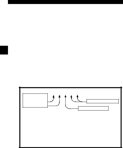
The DTCs format and general code types are shown below.
Bx - Body |
P 0 1 0 1 |
|
|||
Cx - Chassis |
|
|
|
||
Px - Powertrain |
|
Specific Fault Designation |
|||
Ux - Network Comm. |
|
||||
|
|
||||
x = 0, 1, 2 or 3 |
|
|
|||
|
|
|
|
Vehicle Specific System |
|
Example: |
|
|
|
||
P0101 - Mass or Volume Air Flow Circuit Range/Performance Problem |
|||||
Powertrain Codes |
Body Codes |
||||
P0xxx - Generic (SAE) |
B0xxx - Generic (SAE) |
||||
P1xxx |
- Manufacturer Specific |
B1xxx |
- Manufacturer Specific |
||
P2xxx |
- Generic (SAE) |
B2xxx |
- Manufacturer Specific |
||
P30xx-P33xx |
- Manufacturer Specific |
B3xxx |
- Generic (SAE) |
||
P34xx-P39xx |
- Generic (SAE) |
Network Communication Codes |
|||
Chassis Codes |
|||||
U0xxx - Generic (SAE) |
|||||
C0xxx - Generic (SAE) |
U1xxx |
- Manufacturer Specific |
|||
C1xxx |
- Manufacturer Specific |
U2xxx |
- Manufacturer Specific |
||
C2xxx |
- Manufacturer Specific |
U3xxx |
- Generic (SAE) |
||
C3xxx |
- Generic (SAE) |
|
|
||
Within each category (Powertrain, Chassis, Body and Network) of DTCs there are assigned ranges for different vehicle systems.
2 – 8 • • • • • • • • • • • • • • • • • • • • • • • • • • • • • • • • • • • • • • • • • • • • • • • • • • • • • • • •

Using The Scan Tool
Section 3 – Using The Scan Tool
The Scan Tool
1LCD Display – backlit, 128 x 64 pixel display with contrast adjustment.
2 UP and
  DOWN arrow keys – moves selection UP or DOWN.
3 |
ENTER key – selects displayed items. |
|
|
4 |
LEFT and |
RIGHT arrow keys – selects YES or NO, and selects data |
|
|
parameters for custom data list. |
|
|
5 |
BACK key – goes to the previous screen or level. |
|
|
6 |
ON/OFF key – turns power ON or OFF. |
|
|
7 |
CodeConnect® – allows the operator to access vehicle-specific repair |
3 |
|
|
information. |
|
|
8DLC Cable – provides connection for vehicle interface.
9USB Port – provides a USB connection for the computer.
10Serial Number Plate – provides serial number of Scan Tool.
11Battery Compartment – provides power to the Scan Tool when reprogramming from a personal computer or off-vehicle reviewing of codes and printing.
Side of Scan Tool |
1 |
|
3 |
5 
Back of Scan Tool
• • • • • • • • • • • • • • • • • • • • • • • • • • • • • • • • • • • • • • • • • • • • • • • • • • • • • • • • • 3 – 1

Using The Scan Tool
Specifications
Display: Backlit, 128 x 64 pixel display with contrast adjust
Operating Temperature: 0 to 50°C (32 to 122°F)
Storage Temperature: -20 to 70°C (-4 to 158°F)
Internal Power: 4-AAA Batteries External Power: 7 to 16 Volts
A minimum of 8.0 V is required for most control modules to operate properly in a vehicle.
3
Dimensions: |
Height |
Width |
Length |
|
1.36" |
3.40" |
5.60" |
|
34.54 mm |
86.36 mm |
143.76 mm |
3 – 2 • • • • • • • • • • • • • • • • • • • • • • • • • • • • • • • • • • • • • • • • • • • • • • • • • • • • • • • •

Using The Scan Tool
Display
The display has a large viewing area for displaying messages, instructions, and diagnostic information.
The back-lit liquid crystal display (LCD) is a 128 x 64 pixel display.
Characters used to help operate the Scan Tool are:
Indicates information is available for an item or multiple items.
Indicates additional information is available on previous screen by using the  UP arrow key.
Indicates additional information is available on next screen by using the  DOWN arrow key.
Indicates internal batteries need replaced or are not installed. 3
C o d
eIndicates CodeConnect® Key is active.
Indicates graphical viewing available.
Keypad
The keypad is used to move through the different menus of the Scan Tool. The Scan Tool’s software is designed for ease in operating and navigating through menus.
!CAUTION
!CAUTION
Do not use solvents such as alcohol to clean keypad or display. Use a mild nonabrasive detergent and a soft cotton cloth.
Do not soak keypad as water might find its way inside the Scan Tool.
• • • • • • • • • • • • • • • • • • • • • • • • • • • • • • • • • • • • • • • • • • • • • • • • • • • • • • • • • 3 – 3

Using The Scan Tool
Power
Internal Battery
Battery power is not required to use tool.
 ON/OFF button on Scan Tool turns tool on and off.
Press and hold  ON/OFF key for at least 1 second to turn on Scan Tool.
The Scan Tool will automatically turn OFF after a user-selectable period of inactivity when powered from the internal batteries.The default is 2 minutes.
When powered from the internal batteries, the Scan Tool turns off
3 |
the backlighting for the display if no key presses are made during |
a 1-minute period. |
If a key is pressed prior to the Scan Tool powering off, the backlighting for the display will turn back on.
The Scan Tool must be attached to the vehicle to perform diagnostic functions. The Scan Tool disables the diagnostic functions when powered from the internal batteries.
Each time the Scan Tool is
powered up, voltage of the |
|
|
|
Main Menu |
|
|
|
internal battery is checked. |
===================== |
||
If voltage is low, the Low |
Vehicle Diagnostics |
|
|
Component Locator |
|
|
|
Battery Symbol ( ) |
Review Data |
|
|
|
Acronyms |
|
|
displays on screen. |
Print Data |
|
|
Replace the battery using |
Code Lookup |
|
|
instructions provided in |
|
Battery Replacement. |
|
If the Scan Tool will not be used for an extended ! CAUTION period of time, remove the batteries to prevent
battery leakage from damaging the battery compartment.
3 – 4 • • • • • • • • • • • • • • • • • • • • • • • • • • • • • • • • • • • • • • • • • • • • • • • • • • • • • • • •

Using The Scan Tool
Vehicle Power
When the Scan Tool is connected to the vehicle’s DLC, the tool is powered by the vehicle and will automatically turn on once connected.
USB Power
When the tool is connected to a Personal Computer (PC) via the USB cable, the tool will automatically power up.
Refer to Scan Tool Does Not Power Up in Section 5
Troubleshooting if there are problems.
3
System Setup
System Setup allows:
Measurement units to be changed.
Display contrast to be changed.
Auto-Power off time to be changed.
Print Header to be turned ON or OFF.
Scan Tool information to be viewed.
Display to be checked.
Operation of the keypad to be checked.
Memory of the tool to be checked.
Scan Tool to be upgraded.
Language to be changed.
Quick Test to be turned ON or OFF.
Long PID names to be turned ON or OFF.
• • • • • • • • • • • • • • • • • • • • • • • • • • • • • • • • • • • • • • • • • • • • • • • • • • • • • • • • • 3 – 5

Using The Scan Tool
From Main Menu:
1.Select System Setup.
•Use  UP or
UP or  DOWN arrow key until System Setup is highlighted.
•Press  ENTER.
Main Menu
=====================
Component Locator |
|
Acronyms |
|
Review Data |
|
Print Data |
|
Code Lookup |
|
|
|
System Setup |
|
3Changing Measurement Units
English is the default measurement unit.
Measurement units can be changed in View and Record Data.
From System Setup screen:
1.Select English/Metric.
•Use  UP or
UP or  DOWN arrow key until English/Metric is highlighted.
•Press  ENTER.
2.Select Desired Measurement Unit.
•Use  UP or
UP or  DOWN arrow key until desired unit is highlighted.
System Setup
=====================
English/Metric
Adjust Contrast
Auto-Power Off
Quick Test
Print Header
Language Setup
Measurement Units
=====================
English
Metric
3.Save Measurement Setting.
•Press  ENTER.
3 – 6 • • • • • • • • • • • • • • • • • • • • • • • • • • • • • • • • • • • • • • • • • • • • • • • • • • • • • • • •
 Loading...