


8VHU’ V 0DQXDO
&3
&3
6XSHU $XWR6FDQQHU Œ

Tool Information
Complete the following list using the function “Tool Information” on
page 2-5. Provide this information when contacting customer support.
Serial No:
SW ID:
HW Ver:
Boot Ver:
Prod ID:
Board ID:
Burn Date:
Burn Loc:
Copyright Information
Copyright © 2004 Actron Manufacturing, Inc.
All rights reserved.
The information, specifications and illustrations in this manual are based on the latest information available at the time of printing. Actron Manufacturing reserves the right to make changes at any time without notice.
6DIHW\ 3UHFDXWLRQV !
For your safety, read this manual thoroughly before operating your Super AutoScanner™. The safety messages presented below and throughout this user’s manual are reminders to the operator to exercise extreme care when using this test instrument.
Before using the scan tool, always refer to and follow safety messages and applicable test procedures provided by the manufacturer of the vehicle or equipment being tested.
Use equipment only as described in this manual.
Read All Instructions
Read, understand and follow all safety messages and instructions in this manual and on the test equipment. Safety messages in this section of the manual contain a signal word with a three-part message and, in some instances, an icon. The signal word indicates the level of the hazard in a situation.
Safety Messages
Safety messages are provided to help prevent personal injury and equipment damage. All safety messages are introduced by a signal word indicating the hazard level. The types of safety messages are:
!DANGER
!WARNING
!CAUTION
IMPORTANT
Indicates an imminently hazardous situation which, if not avoided, will result in death or serious injury to the operator or to bystanders.
Indicates a potentially hazardous situation which, if not avoided, could result in death or serious injury to the operator or to bystanders.
Indicates a potentially hazardous situation which, if not avoided, may result in moderate or minor injury to the operator or to bystanders.
Indicates a situation which, if not avoided, may result in damage to the test equipment or vehicle.
Safety messages contain three different type styles.
•Normal type states the hazard.
•Bold type states how to avoid the hazard.
•Italic type states the possible consequences of not avoiding the hazard.
Example:
Engine systems can malfunction expelling fuel, oil vapors, hot steam, hot toxic exhaust gases, acid, refrigerant and other debris.
Wear safety goggles and protective gloves, user and bystander. Everyday eyeglasses only have impact resistant lenses, they are NOT safety glasses.
Engine systems that malfunction can cause injury.
• • • • • • • • • • • • • • • • • • • • • • • • • • • • • • • • • • • • • • • • • • • • • • • • • • • • • • Safety – i
Safety Precautions • • • • • • • • • • • • • • • • • • • • • • • • • • • • • • • • • • • • • • • • • • • • • • • • • • • • •
! Important Safety Instructions
! DANGER
Some vehicles are equipped with air bags. You must follow vehicle service manual’s warnings when working around the air bag components or wiring. If the service manual’s instructions are not followed, the air bag may open up unexpectedly, resulting in personal injury. Note that the air bag can still open up several minutes after the ignition key is off (or even if the vehicle battery is disconnected) because of a special energy reserve module.
Risk of electric shock.
•Do not exceed voltage limits between inputs as indicated in the “Specifications” on page 2-2.
•Use extreme caution when working with circuits that have greater than 60 volts DC or 24 volts AC.
Electric shock can cause injury.
Risk of explosion.
•Wear safety goggles and protective clothing, user and bystander. Everyday eyeglasses only have impact resistant lenses, they are NOT safety glasses.
•Do not use this system in environments where explosive vapor may collect, such as in below-ground pits, confined areas, or areas that are less than 18 inches above the floor.
•Use this equipment in locations with mechanical ventilation providing at least four air changes per hour.
•Flammable fuel and vapors can ignite.
•Do not smoke, strike a match, or cause a spark in the vicinity of the battery. Battery gases can ignite.
•Avoid making accidental connection between battery terminals. Do not place uninsulated metal tools on the battery.
•When removing battery cables, remove ground cable first.
•Avoid sparks when connecting or disconnecting power leads to battery.
•Be sure ignition is OFF, headlights and other accessories are OFF and vehicle doors are closed before disconnecting battery cables. This also helps prevent damage to on-board computer systems.
•Always disconnect battery ground connections before servicing electrical system components.
Explosion can cause injury.
! WARNING |
Risk of poisoning.
•Use this equipment in locations with mechanical ventilation providing at least four air changes per hour. Engine exhaust contains odorless lethal gas.
•Route exhaust outside while testing with engine running.
Poisoning can result in death or serious injury.
Safety – ii • • • • • • • • • • • • • • • • • • • • • • • • • • • • • • • • • • • • • • • • • • • • • • • • • • • • •
• • • • • • • • • • • • • • • • • • • • • • • • • • • • • • • • • • • • • • • • • • • • • • • • • • • • • Safety Precautions
! WARNING |
Battery acid is a highly corrosive sulfuric acid. |
! |
•Wear safety goggles and protective gloves, user and bystander. Everyday eyeglasses only have impact resistant lenses, they are NOT safety glasses.
•Make sure someone can hear you or is close enough to provide aid when working near a battery.
•Have plenty of fresh water and soap nearby. If battery acid contacts skin, clothing, or eyes, flush exposed area with soap and water for 10 minutes.
•Seek medical help.
•Do not touch eyes while working near battery.
Battery acid can burn eyes and skin.
Risk of fire.
•Wear safety goggles and protective clothing, user and bystander. Everyday eyeglasses only have impact resistant lenses, they are NOT safety glasses.
•Do not position head directly over or in front of throttle body. Do not pour gasoline down throttle body when cranking or running engine, when working with fuel delivery systems or any open fuel line. Engine backfire can occur when air cleaner is out of position.
•Do not use fuel injector cleaning solvents when performing diagnostic testing.
•Keep cigarettes, sparks, open flame and other sources of ignition away from vehicle.
•Keep a dry chemical (Class B) fire extinguisher rated for gasoline, chemical and electrical fires in work area.
Fire can cause death or serious injury.
Risk of flying particles.
Wear safety goggles while using electrical equipment. Electrical equipment or rotating engine parts can cause flying particles.
Flying particles can cause eye injury.
Risk of burns.
Batteries can produce a short-circuit current high enough to weld jewelry to metal. Remove jewelry such as rings, bracelets and watches before working near batteries.
Short circuits can cause injury.
! WARNING |
Risk of burns.
•Do not remove radiator cap unless engine is cold. Pressurized engine coolant may be hot.
•Do not touch hot exhaust systems, manifolds, engines, radiators, sample probe, etc.
•Wear insulated gloves when handling hot engine components.
•Tester leads can become hot after extended testing in close proximity to manifolds etc.
Hot components can cause injury.
• • • • • • • • • • • • • • • • • • • • • • • • • • • • • • • • • • • • • • • • • • • • • • • • • • • • • Safety – iii

Safety Precautions • • • • • • • • • • • • • • • • • • • • • • • • • • • • • • • • • • • • • • • • • • • • • • • • • • • • •
!
! WARNING
P R N DL2
Risk of expelling fuel, oil vapors, hot steam, hot toxic exhaust gases, acid, refrigerant and other debris.
•Wear safety goggles and protective clothing, user and bystander. Everyday eyeglasses only have impact resistant lenses, they are NOT safety glasses.
•Engine systems can malfunction expelling fuel, oil vapors, hot steam, hot toxic exhaust gases, acid, refrigerant and other debris.
Fuel, oil vapors, hot steam, hot toxic exhaust gases, acid, refrigerant and other debris can cause serious injury.
The engine compartment contains electrical connections and hot or moving parts.
•Keep yourself, test leads, clothing and other objects clear of electrical connections and hot or moving engine parts.
•Do not wear watches, rings, or loose fitting clothing when working in an engine compartment.
•Do not place test equipment or tools on fenders or other places in the engine compartment.
•Barriers are recommended to help identify danger zones in test area.
•Prevent personnel from walking through immediate test area.
Contact with electrical connections and hot or moving parts can cause injury.
Risk of injury.
•This equipment should be operated by qualified personnel only.
•Use this equipment only as described in this manual. Use only the manufacturer’s recommended attachments.
•Do not operate equipment with a damaged cord or if the equipment has been dropped or damaged, until it has been examined by a qualified service representative.
Operation of this equipment by anyone other than qualified personnel may result in injury.
Risk of unexpected vehicle movement.
•Block drive wheels before performing a test with engine running.
•Unless instructed otherwise, set parking brake and put gear selector in neutral for standard transmissions or park for automatic transmissions.
•If vehicle has an automatic parking brake release, disconnect release mechanism for testing and reconnect when testing is completed.
•Do not leave a running engine unattended.
A moving vehicle can cause injury.
Safety – iv • • • • • • • • • • • • • • • • • • • • • • • • • • • • • • • • • • • • • • • • • • • • • • • • • • • •

• • • • • • • • • • • • • • • • • • • • • • • • • • • • • • • • • • • • • • • • • • • • • • • • • • • • • Safety Precautions
! CAUTION
! CAUTION
Risk of equipment or circuit damage. |
! |
•Unless specifically directed by the manufacturer, make sure the ignition is OFF before connecting or disconnecting connectors or any vehicle electrical terminals.
•Do not create a short between battery terminals with a jumper wire or tools.
Improper equipment use can cause equipment or circuit damage.
Misdiagnosis may lead to incorrect or improper repair and/or adjustment.
Do not rely on erratic, questionable, or obviously erroneous test information or results. If test information or results are erratic, questionable, or obviously erroneous, make sure that all connections and data entry information are correct and that the test procedure was performed correctly. If test information or results are still suspicious, do not use them for diagnosis.
Improper repair and/or adjustment may cause vehicle or equipment damage or unsafe operation.
• • • • • • • • • • • • • • • • • • • • • • • • • • • • • • • • • • • • • • • • • • • • • • • • • • • • • Safety – v

Safety Precautions • • • • • • • • • • • • • • • • • • • • • • • • • • • • • • • • • • • • • • • • • • • • • • • • • • • • •
!
Safety – vi • • • • • • • • • • • • • • • • • • • • • • • • • • • • • • • • • • • • • • • • • • • • • • • • • • • •

Table of Contents
Safety Precautions
Part 1 – Getting Started
Manual Conventions . . . . . . . . . . . . . . . . . . . . . . . . . . . . . . . . . . . . . . . . . . 1-1
On-Board Diagnostics . . . . . . . . . . . . . . . . . . . . . . . . . . . . . . . . . . . . . . . . 1-2
Diagnostic Link Connectors (DLC) . . . . . . . . . . . . . . . . . . . . . . . . . . . . . . 1-4
OBD II (J1962) DLC . . . . . . . . . . . . . . . . . . . . . . . . . . . . . . . . . . . . . . . . 1-4
Ford Historic (OBD I) . . . . . . . . . . . . . . . . . . . . . . . . . . . . . . . . . . . . . . . 1-5
GM Historic (OBD I) . . . . . . . . . . . . . . . . . . . . . . . . . . . . . . . . . . . . . . . . 1-6
Chrysler . . . . . . . . . . . . . . . . . . . . . . . . . . . . . . . . . . . . . . . . . . . . . . . . . 1-7
Diagnostic Trouble Codes (DTCs) . . . . . . . . . . . . . . . . . . . . . . . . . . . . . . . 1-8
Vehicle Service Information . . . . . . . . . . . . . . . . . . . . . . . . . . . . . . . . . . . . 1-9
Part 2 – Using The Tool
Tool Description . . . . . . . . . . . . . . . . . . . . . . . . . . . . . . . . . . . . . . . . . . . . . 2-1
Specifications . . . . . . . . . . . . . . . . . . . . . . . . . . . . . . . . . . . . . . . . . . . . . 2-2
Accessories . . . . . . . . . . . . . . . . . . . . . . . . . . . . . . . . . . . . . . . . . . . . . . 2-2
Display . . . . . . . . . . . . . . . . . . . . . . . . . . . . . . . . . . . . . . . . . . . . . . . . . . 2-2
Keyboard . . . . . . . . . . . . . . . . . . . . . . . . . . . . . . . . . . . . . . . . . . . . . . . . 2-3
Power . . . . . . . . . . . . . . . . . . . . . . . . . . . . . . . . . . . . . . . . . . . . . . . . . . . 2-3
Scan Tool Operation . . . . . . . . . . . . . . . . . . . . . . . . . . . . . . . . . . . . . . . . . . 2-4
Tool Power-Up . . . . . . . . . . . . . . . . . . . . . . . . . . . . . . . . . . . . . . . . . . . . 2-4
Tool Navigation . . . . . . . . . . . . . . . . . . . . . . . . . . . . . . . . . . . . . . . . . . . . 2-4
Tool Setup . . . . . . . . . . . . . . . . . . . . . . . . . . . . . . . . . . . . . . . . . . . . . . . 2-4
Vehicle Selection . . . . . . . . . . . . . . . . . . . . . . . . . . . . . . . . . . . . . . . . . . 2-5
Part 3 – Global OBD II Diagnostics
I/M Readiness . . . . . . . . . . . . . . . . . . . . . . . . . . . . . . . . . . . . . . . . . . . . . . . 3-1
Read Codes . . . . . . . . . . . . . . . . . . . . . . . . . . . . . . . . . . . . . . . . . . . . . . . . . 3-4
Erase Codes . . . . . . . . . . . . . . . . . . . . . . . . . . . . . . . . . . . . . . . . . . . . . . . . 3-5
View Data . . . . . . . . . . . . . . . . . . . . . . . . . . . . . . . . . . . . . . . . . . . . . . . . . . . 3-6
View Freeze Data . . . . . . . . . . . . . . . . . . . . . . . . . . . . . . . . . . . . . . . . . . . . . 3-7
Review Data . . . . . . . . . . . . . . . . . . . . . . . . . . . . . . . . . . . . . . . . . . . . . . . . . 3-8
Part 4 – GM Historic Diagnostics
Read Codes . . . . . . . . . . . . . . . . . . . . . . . . . . . . . . . . . . . . . . . . . . . . . . . . . 4-1
Erase Codes . . . . . . . . . . . . . . . . . . . . . . . . . . . . . . . . . . . . . . . . . . . . . . . . 4-2
View Data . . . . . . . . . . . . . . . . . . . . . . . . . . . . . . . . . . . . . . . . . . . . . . . . . . . 4-3
Review Data . . . . . . . . . . . . . . . . . . . . . . . . . . . . . . . . . . . . . . . . . . . . . . . . . 4-4
Field Service . . . . . . . . . . . . . . . . . . . . . . . . . . . . . . . . . . . . . . . . . . . . . . . . 4-4
ToC

Part 5 – Ford Historic Diagnostics
ToC
Read KOEO Codes . . . . . . . . . . . . . . . . . . . . . . . . . . . . . . . . . . . . . . . . . . |
. 5-1 |
Read KOER Codes . . . . . . . . . . . . . . . . . . . . . . . . . . . . . . . . . . . . . . . . . . |
. 5-2 |
Fast or Slow Codes . . . . . . . . . . . . . . . . . . . . . . . . . . . . . . . . . . . . . . . . . |
5-4 |
Computed Timing Check (1984-1991 EEC-IV Vehicles) . . . . . . . . . . . . |
5-5 |
Review Codes . . . . . . . . . . . . . . . . . . . . . . . . . . . . . . . . . . . . . . . . . . . . . . . 5-6
Erase Codes . . . . . . . . . . . . . . . . . . . . . . . . . . . . . . . . . . . . . . . . . . . . . . . . . 5-7
EEC-IV Erase Codes . . . . . . . . . . . . . . . . . . . . . . . . . . . . . . . . . . . . . . . 5-7
MECS Erase Codes . . . . . . . . . . . . . . . . . . . . . . . . . . . . . . . . . . . . . . . . 5-7
Wiggle Test (EEC-IV Vehicles) . . . . . . . . . . . . . . . . . . . . . . . . . . . . . . . . . . 5-8
Output Switch Test (EEC-IV Vehicles) . . . . . . . . . . . . . . . . . . . . . . . . . . . . 5-9
DCL Data Functions (EEC-IV Vehicles) . . . . . . . . . . . . . . . . . . . . . . . . . 5-10
Cyl Balance Test (EEC-IV Vehicles) . . . . . . . . . . . . . . . . . . . . . . . . . . . . . 5-11
IVSC-Speed Ctrl (EEC-IV Vehicles) . . . . . . . . . . . . . . . . . . . . . . . . . . . . . 5-13
STAR Test Mode . . . . . . . . . . . . . . . . . . . . . . . . . . . . . . . . . . . . . . . . . . . . 5-15
Part 6 – Chrysler Historic Diagnostics
Read Codes . . . . . . . . . . . . . . . . . . . . . . . . . . . . . . . . . . . . . . . . . . . . . . . . . 6-1
Erase Codes . . . . . . . . . . . . . . . . . . . . . . . . . . . . . . . . . . . . . . . . . . . . . . . . . 6-3
View Data . . . . . . . . . . . . . . . . . . . . . . . . . . . . . . . . . . . . . . . . . . . . . . . . . . . 6-4
Switch Test . . . . . . . . . . . . . . . . . . . . . . . . . . . . . . . . . . . . . . . . . . . . . . . . . . 6-5
Actuator Test . . . . . . . . . . . . . . . . . . . . . . . . . . . . . . . . . . . . . . . . . . . . . . . . 6-6
Idle Speed Test . . . . . . . . . . . . . . . . . . . . . . . . . . . . . . . . . . . . . . . . . . . . . . 6-7
Sensor Test . . . . . . . . . . . . . . . . . . . . . . . . . . . . . . . . . . . . . . . . . . . . . . . . . 6-7
Review Data . . . . . . . . . . . . . . . . . . . . . . . . . . . . . . . . . . . . . . . . . . . . . . . . . 6-8
Part 7 – Help & Troubleshooting
How to Use On-Line Help . . . . . . . . . . . . . . . . . . . . . . . . . . . . . . . . . . . . . . 7-1 Tool Does Not Power Up . . . . . . . . . . . . . . . . . . . . . . . . . . . . . . . . . . . . . . . 7-1
Using Non-OBD II Adapter Cables . . . . . . . . . . . . . . . . . . . . . . . . . . . . . 7-2 Using J1962 (OBD II) or Chrysler LH Adapter Cable . . . . . . . . . . . . . . . 7-2
Error Messages . . . . . . . . . . . . . . . . . . . . . . . . . . . . . . . . . . . . . . . . . . . . . . 7-3
Vehicle Communication Fault . . . . . . . . . . . . . . . . . . . . . . . . . . . . . . . . . 7-3 Operating Error or Erroneous Data . . . . . . . . . . . . . . . . . . . . . . . . . . . . . 7-3
Battery Replacement . . . . . . . . . . . . . . . . . . . . . . . . . . . . . . . . . . . . . . . . . . 7-4 Tool Self-Tests . . . . . . . . . . . . . . . . . . . . . . . . . . . . . . . . . . . . . . . . . . . . . . . 7-4
Display Test . . . . . . . . . . . . . . . . . . . . . . . . . . . . . . . . . . . . . . . . . . . . . . 7-5 Keyboard Test . . . . . . . . . . . . . . . . . . . . . . . . . . . . . . . . . . . . . . . . . . . . . 7-5 Memory Test . . . . . . . . . . . . . . . . . . . . . . . . . . . . . . . . . . . . . . . . . . . . . . 7-6 Program Mode . . . . . . . . . . . . . . . . . . . . . . . . . . . . . . . . . . . . . . . . . . . . 7-6
Technical Support . . . . . . . . . . . . . . . . . . . . . . . . . . . . . . . . . . . . . . . . . . . . 7-6
Appendix A – Data Link Connectors
Appendix B – Glossary
3DUW *HWWLQJ 6WDUWHG
The SUPER AutoScanner™ was developed by experts in the automotive service industry to help diagnose vehicles and assist in troubleshooting procedures. The tool will monitor vehicle events and to read codes from the computer’s memory to pinpoint problem areas.
All information, illustrations and specifications contained in this manual are based 1 on the latest information available from industry sources at the time of publication. No warranty (expressed or implied) can be made for its accuracy or completeness, nor is any responsibility assumed by the manufacturer or anyone connected with it for loss or damages suffered through reliance on any information contained in this manual or misuse of accompanying product. The manufacturer reserves the right to make changes at any time to this manual or accompanying product without obligation to notify any person or organization of such changes.
MANUAL CONVENTIONS
This manual provides instructions to setup and use your SUPER AUTOSCANNER™. A glossary and application charts provide valuable reference material. Some of the information shown in text or illustrations is obtained using optional equipment. A Sales Representative can help determine option availability. This section contains a list of conventions used.
Safety Messages
Refer to “Safety Precautions” at the beginning of this manual.
Check Note
A check note provides additional information about the subject in the preceding paragraph.
Example:
Make sure the printer is turned on, on-line and connected.
Tips and Lists
Tips and lists provide information that applies to specific systems and processes. Each tip is introduced by this icon for easy identification.
Example:
Use the 83 '2:1 arrow keys to move up/down through the display or move the cursor ([) to a selectable item.
Equipment Damage
Situations arise during testing that could damage the vehicle or the test equipment. The word IMPORTANT signals these situations.
Example:
Screens may differ slightly for vehicle make and year.
Functions and Selections
Diagnostic and tool functions performed by the tool are highlighted in bold.
Example:
Select Read Codes and press (17(5.
• • • • • • • • • • • • • • • • • • • • • • • • • • • • • • • • • • • • • • • • • • • • • • • • • • • • • • • • • 1 – 1

Getting Started • • • • • • • • • • • • • • • • • • • • • • • • • • • • • • • • • • • • • • • • • • • • • • • • • • • • • • • •
Menus
The menus on the tool display are referenced in the procedures and are highlighted in bold-italic text.
Example:
Press the (17(5 key to return to theGM Function List.
Questions and Responses
Messages and user responses are CAPITALIZED.
1 Example:
Selecting NO displays a COMMAND CANCELLED message prompting you to press (17(5 to continue back to the OBDII Function List.
Manual References
Used to reference other sections of the manual. References include the “Title” and page number (section-page).
Example:
Complete the following list using the function “Tool Information” on page 2-5.
Screens
The screens are presented as examples and may change as the software is updated.
Example: |
!3;@ !7@G |
^ |
|
||
|
[ *7:;5>7 ;39@AE;E |
|
|
(AA> '7FGB |
] |
|
(AA> '7>8W(7EFE |
|
ON-BOARD DIAGNOSTICS
The original on-board diagnostics (OBD I) lacked consistency in communication and interface while allowing different interpretations amongst vehicle manufacturers. Ford used several types of engine control computers, Chrysler used several types of data link connectors and GM varied the trouble codes and communication protocols from year-to-year.
The following tables highlight changes for GM, Ford, and Chrysler. If this seems confusing; don’t worry. Your tool makes it easy. Based on the VIN information selected during Scan Tool setup, the processor is automatically recognized. All you have to do is choose the correct adapter cable and jumper wires (if necessary). Details on adapter cables and jumper wires may be found in “Diagnostic Link Connectors (DLC)” on page 1-4.
GM On-Board Diagnostics
System |
Years |
Description |
|
|
Most vehicles used the 12-pin ALDL (Assembly Line Data Link) |
OBD I Control Module |
1981–1995 |
located under the dash on the driver side. Some 94-95 vehicles |
used the 16-pin OBD II (J1962) data link connector (DLC), but |
||
|
|
use the Historical application software. Refer to the vehicle’s |
|
|
Vehicle Emission Control Information label. |
|
|
|
OBD II Control Module |
1994*-Present |
Complies with OBD II regulations and uses the J1962 DLC. |
* OBD II system used in certain 1994-1995 vehicles equipped with a 2.2L, 2.3L, 3.8L, 4.3L or 5.7L engines.
1 – 2 • • • • • • • • • • • • • • • • • • • • • • • • • • • • • • • • • • • • • • • • • • • • • • • • • • • • • • • • •

• • • • • • • • • • • • • • • • • • • • • • • • • • • • • • • • • • • • • • • • • • • • • • • • • • • • • • • • Getting Started
Ford On-Board Diagnostics
System |
Long Name |
Years |
Description |
|
|
MCU |
Microprocessor Control Unit |
1980 |
–1991 |
Used in police vehicles, containing carbureted |
|
engines. Uses the MCU DLC. |
|
||||
|
|
|
|
|
|
|
|
|
|
|
|
EEC-IV |
Electronic Engine Control, |
1984 |
–1995 |
Most Ford vehicles equipped with North American |
|
|
Fourth generation |
|
|
engines. Uses the EEC-IV DLC. |
|
MECS |
Mazda Electronic Control |
1988 |
–1995 |
Vehicles equipped with Mazda-sourced engines. |
|
System |
Uses MECS 6-pin and 17-pin DLCs. |
|
|||
|
|
|
|
||
EEC-V |
Electronic Engine Control, |
1994* – present |
Complies with OBD II regulations and uses the |
1 |
|
Fifth generation |
OBD II J1962 DLC. |
||||
|
|
|
|
|
|
PTEC |
Powertrain Electronic Con- |
2000 |
– present |
Complies with OBD II regulations and uses the |
|
|
troller |
|
|
OBD II J1962 DLC. |
|
* EEC-V OBD II system used in 1994-1995 vehicles equipped with a 3.8L or 4.6L engine.
Chrysler On-Board Diagnostics
System |
Long Name |
Years |
Description |
|
SMEC |
Single Module |
1989–1990 |
Used a 6-pin Serial Communication Interface (SCI) DLC |
|
Engine Controller |
and has bidirectional capability. |
|||
|
|
|||
|
|
|
|
|
SBEC |
Single Board Engine |
1989*–1995 |
Used two types of DLCs: a 6-pin SCI and a 6-pin LH series. |
|
|
Controller |
|
The first to allow a tool to reset the EMR light on trucks. |
|
OBD II |
OBD II Powertrain |
1995**– present |
Complies with OBD II regulations and uses the OBD II |
|
PCM |
Control Module |
J1962 DLC. |
||
|
|
|
|
|
JTEC |
Jeep/Truck Engine |
|
Complies with OBD II regulations and uses the OBD II |
|
1996– present |
J1962 DLC. |
|||
Controller |
||||
|
|
The JTEC system is used on light-duty trucks and Jeeps |
||
|
|
|
*In 1989, the SBEC system was installed in selected vehicles with 3.0L V6 engines.
**Some vehicles in 1995 were equipped with the OBD II PCM.
OBD II stands for On-Board Diagnostics version II. OBD II is a system that the Society of Automotive Engineers (SAE) developed to standardize automotive electronic diagnosis. Technicians now can use the same tool to test any OBD II compliant vehicles without special adapters. The established SAE guidelines are:
•a universal diagnostic test connector, called the data link connector (DLC), with dedicated pin assignments.
•a standardized location for the DLC, visible under the dash on the driver’s side.
•a standardized list of diagnostic trouble codes (DTCs) used by all manufacturers.
•a standardized list of parameter identification (PID) data used by all manufacturers.
•the ability of the vehicle system to record a freeze frame of the operating conditions when a fault occurs.
•expanded diagnostic capabilities that records a code whenever a condition occurs that effects vehicle emissions.
•the ability to clear stored codes from vehicle memory with the scan tool.
In addition, SAE has published hundreds of pages of text defining a standard communications protocol that establishes the hardware, software, and circuit parameters of OBD II systems. Unfortunately, vehicle manufacturers have different interpretations of this standard communications protocol. As a result, the generic OBD II communications scheme used will vary, depending on the vehicle.
• • • • • • • • • • • • • • • • • • • • • • • • • • • • • • • • • • • • • • • • • • • • • • • • • • • • • • • • • 1 – 3
|
Getting Started • • • • • • • • • • • • • • • • • • • • • • • • • • • • • • • • • • • • • • • • • • • • • • • • • • • • • • • • |
|
SAE publishes recommendations, not laws, but the Environmental Protection |
|
Agency (EPA) and California Air Resources Board (CARB) made many of SAE’s |
|
recommendations legal requirements that vehicle manufacturers were required |
|
to phase in over a three-year period. Beginning in 1994, vehicles with a new |
|
engine management computer – about 10% of each manufacturers fleet – were |
|
supposed to comply with OBD II standards. For 1995, OBD II systems were to |
|
appear on about 40% of the new vehicles sold in the USA. Some of the 1994-1995 |
|
OBD II systems were not fully compliant, so the Government granted waivers to |
1 |
give manufacturers time to fine-tune their systems. Beginning in 1996, most of the |
new vehicles sold in the USA were fully OBD II compliant. |
|
|
|
DIAGNOSTIC LINK CONNECTORS (DLC)
The Data Link Connector (DLC) allows the scan tool to communicate with the vehicle’s computer(s). Before OBD II, manufacturers used different data link connectors to communicate with the vehicle. The proper DLC adapter cable must be used to connect the tool to the vehicle. Also, the vehicle’s DLC may be found in several different places and have many different configurations. The following describes the DLCs used by Ford, GM and Chrysler. The DLC location and types for domestic vehicles can be looked up in the charts in “Appendix A – Data Link Connectors” .
OBD II (J1962) DLC
Beginning in 1996, vehicles sold in the United States use the J1962 DLC, a
term taken from a physical and electrical specification number
assigned by SAE (J1962). OBD II defines the physical and electrical
specification for the DLC. The DLC
should be located under the dashboard on the driver side of the vehicle. If the DLC is not located under the dashboard as stated, a decal describing its location should be attached to the dashboard in the area the DLC should have been located.
Because the OBD II J1962 connector has power and ground, you only need a single cable connection to the tool for both power and tool communications. Attach the OBD II adapter cable to the extender cable, both supplied with the tool, to connect the tool. Certain pins in the connector are reserved.
1 - |
Manufacturer Reserved |
|
1 |
|
|
|
|
|
|
|
|
|
|
|
|
|
|
|
8 |
|
|||
2 - |
J1850 Bus+ |
|
|
|
|
|
|
|
|
|
|
|
|
|
|
|
|
|
|
|
|
|
|
3 - |
Manufacturer Reserved |
|
|
|
|
|
|
|
|
|
|
|
|
|
|
|
|
|
|
|
|
|
|
4 - |
Chassis Ground |
|
|
|
|
|
|
|
|
|
|
|
|
|
|
|
|
|
|
|
|
|
|
|
|
|
|
|
|
|
|
|
|
|
|
|
|
|
|
|
|
|
|
|
|||
5 - |
Signal Ground |
|
|
|
|
|
|
|
|
|
|
|
|
|
|
|
|
|
|
|
|
|
|
6 - |
CAN High, J-2284 |
|
|
|
|
|
|
|
|
|
|
|
|
|
|
|
|
|
|
|
|
|
|
|
|
|
|
|
|
|
|
|
|
|
|
|
|
|
|
|
|
|
|
|
|||
7 - |
K Line, ISO 9141-2 & ISO/DIS 14230-4 |
|
9 |
|
|
|
|
|
|
|
|
|
|
|
|
|
|
16 |
|
||||
|
|
|
|
|
|
|
|
|
|||||||||||||||
8 - |
Manufacturer Reserved |
|
|
|
|
|
|
|
|
|
|
|
|
|
|
|
|
|
|
|
|
|
|
9 - |
Manufacturer Reserved |
13 |
- Manufacturer Reserved |
|
|
|
|||||||||||||||||
10 |
- J1850 Bus |
14 |
- CAN Low, J-2284 |
|
|
|
|||||||||||||||||
11 |
- Manufacturer Reserved |
15 |
- L Line, ISO 9141-2 & ISO/DIS 14230-4 |
||||||||||||||||||||
12 |
- Manufacturer Reserved |
16 |
- Battery Power |
|
|
|
|||||||||||||||||
|
|
|
|
|
|
|
|
|
|
|
|
|
|
|
|
|
|
|
|
|
|
|
|
1 – 4 • • • • • • • • • • • • • • • • • • • • • • • • • • • • • • • • • • • • • • • • • • • • • • • • • • • • • • • • •

• • • • • • • • • • • • • • • • • • • • • • • • • • • • • • • • • • • • • • • • • • • • • • • • • • • • • • • • Getting Started
Ford Historic (OBD I)
Since 1984, Ford used several different types of powertrain control modules (PCM). Refer to “On-Board Diagnostics” on page 1-2. With the proper adapter cables, your tool will be able to read these systems as well.
IMPORTANT |
Use the Battery Power cable to provide 12V to the tool for all |
|
systems. |
|
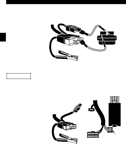
EEC-IV System
The EEC-IV computer system u s e s a l a r g e s i x - s i d e d c o n n e ct o r a n d a p i g ta i l connector.
MCU System
The MCU computer system uses the same six - sided connector, but NOT the pigtail connector. Leave the pigtail unattached.
Cable Adapter |
|
|
|
|
|
Vehicle DLC |
|
|
|
|
||||||||||||||||||||||
|
|
|
1 |
|||||||||||||||||||||||||||||
EEC-IV/MCU |
|
|
|
|
|
|
EEC-IV/MCU |
|
|
|
||||||||||||||||||||||
P/N CP9128 |
|
|
|
|
|
|
|
|
|
|
|
|
|
|
|
|
|
|
|
|
|
|
|
|
|
|
|
|
|
|||
To Scan |
|
|
|
|
|
|
|
|
|
|
|
|
|
|
|
|
|
|
|
|
|
|
|
|
|
|
|
|
|
|
||
|
|
|
|
|
|
|
|
|
|
|
|
|
|
|
|
|
|
|
|
|
|
|
|
|
|
STI Pigtail |
||||||
Tool |
|
|
|
|
|
|
|
|
|
|
|
|
|
|
|
|
|
|
|
|
|
|
|
|
|
|
EEC-IV only |
|||||
|
|
|
|
|
|
|
|
|
|
|
|
|
|
|
|
|
|
|
|
|
|
|
|
|
|
|
|
|
|
|
|
|
|
|
|
|
|
|
|
|
|
|
|
|
|
|
|
|
|
|
|
|
|
|
|
|
|
|
|
|
|
|
|
|
|
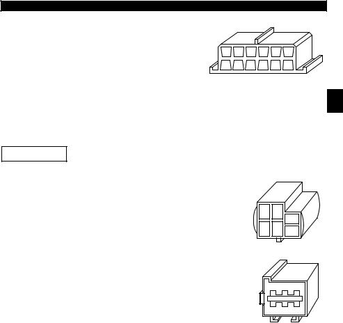
MECS (Mazda Electronic Control System)
MECS vehicles (1988 –1995) use either a 6-pin (with pigtail) or a 17-pin DLC. The 6-pin MECS adapter cable and jumper wires (P/N 9131) are used to connect the tool to both DLCs. Both adapter cables are also available through your dealer.
6-Pin MECS. |
Cable Adapter |
Vehicle DLC |
|
6-Pin MECS |
6-Pin MECS |
|
P/N CP9131 |
|
|
To Scan |
|
|
Tool |
|
P igta il
4 |
5 |
6 |
1 |
2 |
3 |
|
||
|
|
STI Pigtail
Clip to good
Vehicle ground
• • • • • • • • • • • • • • • • • • • • • • • • • • • • • • • • • • • • • • • • • • • • • • • • • • • • • • • • • 1 – 5
1
Getting Started • • • • • • • • • • • • • • • • • • • • • • • • • • • • • • • • • • • • • • • • • • • • • • • • • • • • • • • •
17-Pin MECS |
|
|
Vehicle DLC |
Us e t h e 6 - P i n |
|
Adapter Cable |
|
M E CS a n d t h e |
|
6-Pin MECS |
17-Pin MECS |
jumper wires. |
To |
P/N CP9128 |
|
|
|
Scan Tool
STI Pigtail
4 |
5 |
6 |
|
3 |
|||
2 |
|||
1 |
|||
|
|||
|
|
STO
Clip to good vehicle ground
MECS Ford Probe
Certain Probes have a WHITE TACH CONNECTOR located very IMPORTANT close to the 6-pin Self-Test connector and bundled in the same
wiring harness. This is NOT the STI (Self Test Input) Pigtail.
Connect the pigtail to t h e B L A C K S T I c o n n e ct o r l o c a t e d farther back on the wire harness. If the tool is c o n n e ct e d t o t h e
W H I T E Ta ch con nect or, seriou s damage will result and may void warranty. Refer to the illustration.
|
Cable Adapter |
Vehicle DLC |
|||
|
6-Pin MECS |
6-Pin MECS |
|||
|
P/N CP9128 |
|
|
||
|
|
|
STI |
|
|
|
|
Pigtail |
|
|
|
To |
|
|
|
|
Windshield |
Scan |
|
|
BLACK STI |
|
|
Tool |
|
|
|
Wiper |
|
|
|
|
Connector |
|
Motor |
|
4 |
5 |
6 |
|
|
|
3 |
|
|
||
|
1 |
2 |
|
|
|
|
|
|
|
||
|
6-Pin MECS |
|
|
||
|
|
|
|
|
WHITE |
|
|
|
6-Pin MECS |
Tach |
|
|
|
|
Connector |
||
|
|
|
|
|
|
|
|
|
|
|
DO NOT USE! |
|
Clip to good |
|
|
||
|
vehicle ground |
|
|
||
GM Historic (OBD I)
Prior to1996, most GM vehicles used the standard 12-pin Assembly Line Diagnostic Link (ALDL). Use the GM ALDL cable kit (p/n CP9127) which includes the ALDL adapter and cigarette lighter power cable for these vehicles. In 1994 & 1995, certain GM vehicles used the J1962 DLC.
IMPORTANT |
Use the Battery Power cable to provide 12V to the tool. |
|
1 – 6 • • • • • • • • • • • • • • • • • • • • • • • • • • • • • • • • • • • • • • • • • • • • • • • • • • • • • • • • •
• • • • • • • • • • • • • • • • • • • • • • • • • • • • • • • • • • • • • • • • • • • • • • • • • • • • • • • • Getting Started
ALDL ALDL (P/N CP9127)
The ALDL DLCs are usually located under the dashboard on the driver’s side.
F E D C B A
G H J K L M
Corvettes & Fieros:
Sometimes, the DLC is located in the center console behind the ashtray. Refer to vehicle service manual for exact location. It may be in full view, or it may be 1 recessed behind a panel. An opening in the panel should allow access to the recessed connector.
Chrysler
IMPORTANT
SCI
Use the Battery Power cable to provide 12V to the tool for both systems.
SCI (P/N CP9129)
The SCI (serial communications interface) DLC is a 6-pin connector located in the engine compartment. The adapter cable to be used on these vehicles is supplied with the tool. This cable is labeled CHRY on the 15 pin DB style connector and SCI on the vehicle end.
LH-series |
LH (P/N CP9130) |
The LH-series data link connector is used on LH platform vehicles. The LH style DLC is a small, blue, rectangular 6-pin connector located in the passenger compartment below the dashboard to the right of the steering column.
The LH Adapter Cable (P/N CP9130) is optional and must be purchased separately.
• • • • • • • • • • • • • • • • • • • • • • • • • • • • • • • • • • • • • • • • • • • • • • • • • • • • • • • • • 1 – 7
Getting Started • • • • • • • • • • • • • • • • • • • • • • • • • • • • • • • • • • • • • • • • • • • • • • • • • • • • • • • •
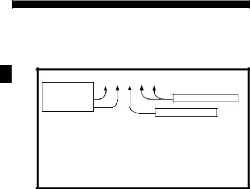
DIAGNOSTIC TROUBLE CODES (DTCS)
Diagnostic Trouble Codes (DTCs) consist of a five-digit alphanumeric code. The DTC format and general code types are shown below. When the on-board computer recognizes and identifies a problem, a DTC for that fault is stored in memory. These codes are intended to help you determine the root cause of a problem
|
. |
|
1 |
P 0 1 0 1 |
|
|
||
|
Bx - Body |
|
|
Cx - Chassis |
|
|
Px - Powertrain |
Specific Fault Designation |
|
Ux - Network Comm. |
|
|
|
|
|
x = 0, 1, 2 or 3 |
|
|
Example: |
Vehicle Specific System |
|
|
|
|
P0101 - Mass or Volume Air Flow Circuit Range/Performance Problem |
|
|
Powertrain Codes |
Body Codes |
|
P0xxx - Generic (SAE) |
B0xxx - Generic (SAE) |
|
P1xxx - Manufacturer Specific |
B1xxx - Manufacturer Specific |
|
P2xxx - Generic (SAE) |
B2xxx - Manufacturer Specific |
|
P30xx-P33xx - Manufacturer Specific |
B3xxx - Generic (SAE) |
|
P34xx-P39xx - Generic (SAE) |
Network Communication Codes |
|
Chassis Codes |
|
|
U0xxx - Generic (SAE) |
|
|
C0xxx - Generic (SAE) |
U1xxx - Manufacturer Specific |
|
C1xxx - Manufacturer Specific |
U2xxx - Manufacturer Specific |
|
C2xxx - Manufacturer Specific |
U3xxx - Generic (SAE) |
|
C3xxx - Generic (SAE) |
|
J2012 and ISO 15031-6 are standards for all DTCs, established by the SAE, International Organization for Standardization (ISO) and other governing bodies. Codes and the definitions assigned by this specification are known as Generic OBD II codes. OBD II requires compliance of this standard, and has made it a standard for all cars, light trucks, APVs, MPVs, and SUVs sold in the U.S. Codes not reserved by the SAE are reserved for the manufacturer and referred to as Manufacturer Specific.
1 – 8 • • • • • • • • • • • • • • • • • • • • • • • • • • • • • • • • • • • • • • • • • • • • • • • • • • • • • • • • •

• • • • • • • • • • • • • • • • • • • • • • • • • • • • • • • • • • • • • • • • • • • • • • • • • • • • • • • • Getting Started
VEHICLE SERVICE INFORMATION
The following is a list of publishers who have manuals containing electronic engine control diagnostic information. Some manuals may be available at auto parts stores or your local public library. For others, you need to write for availability and pricing, specifying the make, model and year of your vehicle.
Chilton Book Company |
Saturn: |
|
Chilton Way |
Adistra Corporation |
1 |
Radnor, PA 19089 |
c/o Saturn Publications |
|
Haynes Publications |
101 Union St. |
|
|
||
Post Office Box 1000 |
|
|
861 Lawrence Drive |
|
|
Plymouth, MI 48170 |
|
|
Newbury Park, CA 91320 |
|
|
Ford Motor Company: |
|
|
Cordura Publications |
|
|
Ford, Lincoln, & Mercury |
|
|
Mitchell Manuals, Inc. |
|
|
Ford Publication Department |
|
|
Post Office Box 26260 |
|
|
Helm Incorporated |
|
|
San Diego, CA 92126 |
|
|
Post Office Box 07150 |
|
|
Motoríst Auto Repair Manual |
Detroit, MI 48207 |
|
Hearst Company |
Chrysler Corporation: |
|
250 W. 55th Street |
|
|
Chrysler, Plymouth, & Dodge |
|
|
New York, NY 10019 |
Chrysler Motors Service Training |
|
General Motors Corporation: |
26001 Lawrence Avenue |
|
Center Line, MI 48015 |
|
|
Buick, Cadillac, Chevrolet, GEO, GMC, |
|
Oldsmobile, & Pontiac
Helm Incorporated
Post Office Box 07130
Detroit, MI 48207
Suitable manuals have titles such as:
•“Electronic Engine Controls”
•“Fuel Injection and Feedback Carburetors”
•“Fuel Injection and Electronic Engine Controls”
•“Emissions Control Manual”
... or similar titles
• • • • • • • • • • • • • • • • • • • • • • • • • • • • • • • • • • • • • • • • • • • • • • • • • • • • • • • • • 1 – 9

Getting Started • • • • • • • • • • • • • • • • • • • • • • • • • • • • • • • • • • • • • • • • • • • • • • • • • • • • • • • •
Getting Started Notes
1
1 – 10 • • • • • • • • • • • • • • • • • • • • • • • • • • • • • • • • • • • • • • • • • • • • • • • • • • • • • • • •
3DUW 8VLQJ 7KH 7RRO
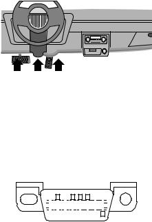
TOOL DESCRIPTION
DB15 Male Connector – provides connection for vehicle interface and for a serial |
|
port via the RS232 Adapter (CP9119) |
|
12V Power Jack– provides power connection. |
|
LCD Display – 4 line x 20 character. |
|
! +(/3 key – accesses the Help function. |
|
" /()7 5,*+7 arrows – Select responses and moves cursor. |
2 |
5 21 2)) key – turns power ON/OFF when not connected to vehicle. |
$ (17(5 key – selects displayed items.
% 83 '2:1 arrows – moves the selection pointer ([) and scrolls UP or DOWN. & %$&. key – go back to previous screens, redo selections or correct mistake.
/ Battery compartment
Front of Tool
|
! |
$ |
" |
|
|
|
% |
|
# |
|
8 |
/
• • • • • • • • • • • • • • • • • • • • • • • • • • • • • • • • • • • • • • • • • • • • • • • • • • • • • • • • • 2 – 1

Using The Tool • • • • • • • • • • • • • • • • • • • • • • • • • • • • • • • • • • • • • • • • • • • • • • • • • • • • • • • •
Specifications
Display: LCD, 4 line, 20 column
Operating Temperature: 0 to 50°C (-32 to 122°F)
Storage Temperature: -20 to 70°C (-4 to 158°F) Internal Power: 9V cell (Type 6LR61)
External Power: 10.0 to 15.5 Volts
Most vehicle control modules require at least 8.0 V to operate properly.
|
Power Dissipation: 3.5 Watts maximum |
|
|
||
|
Dimensions: |
Height |
Width |
Length |
|
|
|
1.563" |
4.5" |
9.125” |
|
2 |
|
|
|||
|
40 mm |
114 mm |
232 mm |
|
|
|
Weight: 33.1oz (918 g) |
|
|
|
|
|
|
|
|
|
|
|
Accessories |
|
|
|
|
|
|
|
|
CP9145 |
CP9150 |
|
Standard 8 ft Extender Cable . . . . . . |
. . . . . . . |
Included |
Included |
|
|
Battery Power Cable . |
. . . . . . . . . . . . |
. . . . . . . |
Optional |
Included |
–includes cigarette lighter adapter
–includes CP9118 Battery Clip Adapter
Adapter Cables: |
|
|
– Standard OBD II (J1962) cable . . . . . . . . . . |
Included |
Included |
– CP9127 GM ALDL cable kit . . . . . . . . . . . . |
Optional |
Included |
– CP9128 Ford EEC-IV/MCU cable kit . . . . . |
Optional |
Included |
– CP9129 Chrysler SCI cable kit . . . . . . . . . . |
Optional |
Included |
– CP9130 Chrysler LH cable kit . . . . . . . . . . |
Optional |
Optional |
– CP9131 Ford MECS cable kit . . . . . . . . . . . |
Optional |
Optional |
CP9119 RS232 Adapter . . . . . . . . . . . . . . . . . . |
Optional |
Optional |
Optional / Replacement Parts are available from the following:
•dealer where you originally purchased your tool.
•manufacturer contact customer service at 1-800-228-7667 (8:00 – 6:00 EST Monday – Friday) or send an email to tech_support@actron.com.
Display
The tool uses a 4 line by 20 character, Liquid Crystal Display (LCD). The large viewing area displays Help messages, instructions, and diagnostic information.
Five characters help you navigate and |
# G@5F;A@ ;EF ^ |
|||
operate the tool: |
[ S&736 ( R A67ES |
\ |
||
^ |
appears in upper right corner of display |
|||
S D3E7 ( R A67ES ] |
||||
|
to indicate Help is available. |
|||
|
S*;7I 3F3 |
|
||
[ identifies the selection. |
||||
] |
indicates additional information is |
|
|
|
|
available on the next screen. |
|
|
|
\ |
indicates additional information is available on the previous screen. |
|
||
|
Low battery symbol will appear in bot- |
$ V !A6O / |
|
|
|
tom right-hand corner of the screen at |
|
||
|
power-up if the internal batteries need |
! $/ |
|
|
|
replacement or are not installed. |
;D5G;F AI @BGF |
] |
|
V |
identifies Pending DTCs in the Global |
|||
|
|
|||
OBD II Read Codes function.
2 – 2 • • • • • • • • • • • • • • • • • • • • • • • • • • • • • • • • • • • • • • • • • • • • • • • • • • • • • • • • •

• • • • • • • • • • • • • • • • • • • • • • • • • • • • • • • • • • • • • • • • • • • • • • • • • • • • • • • • Using The Tool
Keyboard
The tool’s software is designed for ease in operating and navigating through menus. Do not use solvents such as alcohol to clean the keypad or display. Use a mild nonabrasive detergent and a soft cotton cloth. Do not soak the keypad as water might find its way inside the tool.
Power
Refer to “Tool Does Not Power Up” on page 7-1 if you encounter problems.
Internal Battery Power
The tool contains a 9V battery that provides power for remote printing and tool programing. Press and hold down the 21 2)) key for at least one second to turn ON the tool. Each time the tool is powered up, the voltage of the batteries is checked. If the voltage is low, the Low Battery Symbol ( ) displays on the screen. 2 Replace batteries using the instructions provided in “Battery Replacement” on page 7-4.
Power must be provided through the data link connector or 12V power jack. A message displays if power is not connected.
-AG !GEF $>G9 (AA>@FA *7:;5>7
AD (:;E #B7D3F;A@ $D7EE "( & FA A@F
If tool is stored for long periods, remove the batteries to prevent electrolyte leakage from damaging the battery compartment.
To conserve the battery, the scan tool turns Off after 2 minutes.
Vehicle Power
When using the OBD II J1962 or Chrysler LH adapter cables, the power to the tool comes from vehicle Data Link Connector (DLC). The other adapter cables do not provide power to the tool. In these cases, power can be provided from the cigarette lighter, an accessory plug, or the vehicle battery using battery clip adapters. Refer to “Diagnostic Link Connectors (DLC)” on page 1-4.
Some vehicle cigarette lighters are not powered when the ignition is in the OFF position. Therefore, you may wish to use battery clip adapters.
CP9118 Battery Clip Adapter (optional)
Cigarette Lighter Adapter
AC Power Adapter
An AC power adapter can be used to power the tool.
The tool is equipped to accept any 110 Vac - 12 Vdc GND 

 12 V wall adapter with the following specifications:
•300 mA minimum current unregulated wall power adapter.
•Adapter Dimensions:5.5 mm Outside Diameter
•2.5 mm Inside Diameter
•The Inside Tip is positive (+).
•• • • • • • • • • • • • • • • • • • • • • • • • • • • • • • • • • • • • • • • • • • • • • • • • • • • • • • • • 2 – 3
Using The Tool • • • • • • • • • • • • • • • • • • • • • • • • • • • • • • • • • • • • • • • • • • • • • • • • • • • • • • • •
SCAN TOOL OPERATION
To diagnose a vehicle, connect the DLC and power adapter (if applicable) to the scan tool. Refer to “Diagnostic Link Connectors (DLC)” on page 1-4 of Getting Started.
If you just want to power up the tool to do its self-tests, code lookup, or review data from the last vehicle tested, then you do not need to attach the cable to the Data Link Connector. The internal battery provides power for this.
Tool Power-Up
Connect the tool to the vehicle using the appropriate DLC and power connections.
2 |
When the tool powers up, a series of |
|
m e ss a g e s d i s p l a y o n t h e s c r e e n |
beginning with a “Welcome” screen and ending with a “Key Button Help” screen. If you wish to review the key button d e f i n i t i o n s , p u sh t h e +(/3 ke y ; otherwise, press (17(5 to continue.
+7>5A?7 (A (:75FDA@ 'GB7D GFA'53@@7D
X X X
Tool Navigation
User Interface
All menu and lists are intuitive and operate the same way.
Use the 83 '2:1 arrow keys to move up/down through the display or move the cursor ([) to a selectable item.
Press the (17(5 key to select the function or item.
To return to previous screens, press the %$&. key.
This information can be viewed on the tool by pressing the +(/3 key after powering up the tool.
If a list or message contains more than four lines, an arrow icon displays on the
last column of the display to indicate the scrolling direction available: up (\) or down (]). Use the 83 '2:1 arrow keys to move line-by-line through the display.
When the bottom of the list is reached, then only the\ displays. At the top of the list, only the ] displays.
User Responses
The tool may ask a question which requires a YES or NO response — brackets ( )
enclose the default one. To accept the default choice, press the (17(5 key. To change the answer, use the /()7 5,*+7
arrow keys to move the brackets to another response and press (17(5.
Tool Setup
Tool Setup allows you to change the measurement units and display tool information. The settings remain until the internal battery becomes discharged.
*;7I @EFDG5F;A@EAD D73F;@9 GEFA?3F3 ;EF
-7E "A
!3;@ !7@G ^
[*7:;5>7 ;39@AE;E (AA> '7FGB ] (AA> '7>8W(7EF
2 – 4 • • • • • • • • • • • • • • • • • • • • • • • • • • • • • • • • • • • • • • • • • • • • • • • • • • • • • • • • •

• • • • • • • • • • • • • • • • • • • • • • • • • • • • • • • • • • • • • • • • • • • • • • • • • • • • • • • • Using The Tool
Measurement Units
To change the measurement units, use the 83 '2:1 arrow keys to select
English/Metric and press (17(5.
In the Measurement Units menu, select
En gli sh or Metric and then press (17(5. English is the default.
'7FGB (AA>
[ S @9>;E:/!7FD;5S(AA> @8AD?3F;A@
Press (17(5 again to return to the Setup Tool menu.
Tool Information
This function allows you to view specific tool information that may be needed |
|
when contacting customer service. Select Tool Information with the 83 '2:1 |
2 |
arrow keys and press (17(5. |
The information shown to the right displays on the screen. Use the 83 '2:1 arrow
keys to view all the lines.
Press the %$&. or (17(5 key to return to the Setup Tool menu.
(AA> @8AD?3F;A@
[ '7D;3> "A |
|
'+ |
|
+ *7D |
|
AAF *7D |
|
$DA6 |
|
A3D6 |
|
GD@ 3F7 / / |
|
GD@ A5 |
|
Write this information in the space provided on the inside of the front cover.
Vehicle Selection
When the tool powers up, the “Key Button Help” screen is followed by aMain Menu screen.
Pick Vehicle Diagnosis to begin Vehicle Selection.
!3;@ !7@G ^
[*7:;5>7 ;39@AE;E (AA> '7FGB ] (AA> '7>8W(7EF
If there is a previous vehicle present, the tool displays that vehicle. You can choose the last vehicle selected or setup for a new vehicle. The tool retains all data retrieved from the last vehicle selected until any of the following occurs:
A new vehicle is selected
Battery is dead or disconnected
Tool is flash programmed to update software
The last vehicle selected is kept but you choose Erase Data
You can either keep the previously
selected vehicle or change it. If changing the vehicle, press the 5,*+7 arrow key
and press (17(5. Otherwise, press (17(5 to keep the current one.
"7A@
X ' '#
$ "
• • • • • • • • • • • • • • • • • • • • • • • • • • • • • • • • • • • • • • • • • • • • • • • • • • • • • • • • • 2 – 5

Using The Tool • • • • • • • • • • • • • • • • • • • • • • • • • • • • • • • • • • • • • • • • • • • • • • • • • • • • • • • •
Keep Current Vehicle
The next screen asks if you want to erase the stored data. The default is NO.
After pressing (17(5, the function list displays.
Changing the Vehicle
D3E7 >> 'FAD76
3F3 AD '7>75F76 *7:;5>7
- ' "#
Changing vehicles erases all data stored in the tool. The default is YES.
Press (17(5 to continue.
2
$;5=;@9 "7I *7:;5>7D3E7E >> 'FAD763F3X A@F;@G7
- ' "#
Four Vehicle Options are available: General Motors, Ford, Chrysler and Global OBD II. Global OBD II does not require additional information and takes you directly to the function list. The other three require additional information so that the tool and vehicle can communicate. For example, select GENERAL MOTORS.
The menus provide a list of choices and reference the v e h i cl e ’s V I N w h e r e applicable. The VIN is visible from outside the vehicle by looking through t h e b a se o f t h e f ro n t windshield at the top of the dashboard on the driver’s s i d e . B e c a u s e manufacturers use different VIN schemes, the tool will indicate which digit of the VIN to locate for information such as Year, Make and Engine.
Use 83 '2:1 arrow keys to move through the list.
If you make a mistake, press the %$&. key to re turn to th e p re vious menu.
At the last screen, press
(17(5.
'7>75F !3@G835FGD7D
[7@7D3> !AFADEAD6 ]'7>75F:DKE>7D*7:;5>7 (KB7 [ 3D
(DG5=
|
|
|
|
|
'7>75F -73D * " |
|
|
|
|
|
( |
\ |
|
|
[ ' |
] |
|
|
|
|
'7>75F& !3=7 * " |
|
|
|
|
|
|
|
|
|
#>6E?A4;>7 |
|
\ |
|
|
[ G;5= |
] |
|
|
|
'7>75F36;>>35!A67> |
|
|
|
|
$3D= H7@G7 |
|
\ |
|
[&793> ] &'7H;7D3>75F @9;@7 * " > [ X '
! X ' (
! X ' &793>)(#W 'X '
$ "
If a message displays, follow the instructions then press (17(5.
Vehicles manufactured from 2000 to present automatically use Global OBD II Diagnostics even if GM, Ford or Chrysler was selected.
(GD@ 7K #88AD '75A@6E (:7@ (GD@ 7K #@ (:7@ $D7EE "( &
2 – 6 • • • • • • • • • • • • • • • • • • • • • • • • • • • • • • • • • • • • • • • • • • • • • • • • • • • • • • • • •

3DUW *OREDO 2%' ,, 'LDJQRVWLFV
This section covers all OBD II compliant vehicles. Non OBD II vehicles manufactured by GM, Ford and Chrysler are covered in Parts 4, 5 and 6, respectively.
If an Operating Error message displays, refer to “Error Messages” on page 7-3 and check the following :
make sure the OBD II connector is securely attached, and the ignition key is ON. Cycle the ignition key to OFF for 10 seconds, then ON. This may be required to reset the computer. If required, select YES to try again.
the vehicle fails to link because it does not support OBD II diagnostics. Check the emissions label on the vehicle for OBD II compliance.
On the initial link to the vehicle, the scan tool checks the status of the
I/M Monitors and displays it regardless of the function selected.
3
I/M READINESS
The I/M Readiness (Inspection and Maintenance) function is used to check the operations of the Emission System on OBDII vehicles. I/M Readiness is an excellent function to use prior to having a vehicle inspected for compliance to a state emissions program.
During normal driving conditions, the vehicle’s computer scans the emission system. After a specific amount of drive time (depending on vehicle), the computer’s "monitors" will decide if the vehicles emission system is working correctly or not. When the "monitors" record:
•"OK" and check engine light has not come on - vehicle will likely pass emissions test and the system being checked is working properly.
•"INC" (Incomplete) - vehicle was not driven enough and needs to be driven until monitors record "READY."
•"N/A" - vehicle does not support that monitor.
Some states MAY NOT require all monitors to be listed as “READY” to pass the emissions test. Check with state testing site for exact requirements. All states will fail a vehicle who has the "check engine light" lit at time of test.
Depending on vehicle, disconnecting or a discharged battery may erase trouble codes and clear status monitors.
The vehicle may support more than one type of I/M Readiness. The first type shows the status of the monitors since the DTCs were last erased. They are displayed under the heading SINCE DTCs CLEARED. The second type shows the status of the monitors since the start of the current drive cycle, and are displayed under the heading THIS DRIVING CYCLE. If the monitors are not supported for THIS DRIVING CYCLE, then the scan tool only shows monitors for SINCE DTCs CLEARED with no header on line 1.
•• • • • • • • • • • • • • • • • • • • • • • • • • • • • • • • • • • • • • • • • • • • • • • • • • • • • • • • • 3 – 1
 Loading...