


CP9190
CP9190
Elite AutoScanner Pro
P/N 0002-000-2933
®

Copyright Information
Copyright © 2006 SPX Corporation
All rights reserved.
The information, specifications and illustrations in this
guide are based on the latest information available at the
time of printing. SPX Corporation reserves the right to
make changes at any time without notice.
If you have questions or concerns Contact
Technical Support:
•Phone: 1-800-228-7667
•Website: www.actron.com
•Mail:SPX Service Solutions
• 15825 Industrial Parkway
• Cleveland, Ohio 44135
• Attn: Technical Support
Scan Tool Information
Complete the following list using
the function “Tool Information”.
Provide this information when
contacting customer support.
Serial No:
SW ID:
HW Ver:
Boot Ver:
Prod ID:
Board ID:
Burn Date:
Burn Loc:

ToC
i
Table of Contents
Safety Precautions
Important Safety Messages . . . . . . . . . . . . . . . . . . . . . . . . . . . . . . . Safety - iii
Section 1 – Using This Manual
Section 2 – Getting Started
Introduction . . . . . . . . . . . . . . . . . . . . . . . . . . . . . . . . . . . . . . . . . . . . . . . . . 2-1
Using the CD . . . . . . . . . . . . . . . . . . . . . . . . . . . . . . . . . . . . . . . . . . . . . . . . 2-2
Running Applications On Included CD . . . . . . . . . . . . . . . . . . . . . . . . .. 2-3
Vehicle Service Information . . . . . . . . . . . . . . . . . . . . . . . . . . . . . . . . . . . . 2-4
Introduction to On-Board Diagnostics . . . . . . . . . . . . . . . . . . . . . . . . . . . . 2-6
SAE Publications . . . . . . . . . . . . . . . . . . . . . . . . . . . . . . . . . . . . . . . . . .. 2-7
Diagnostic Link Connector (DLC) . . . . . . . . . . . . . . . . . . . . . . . . . . . . . . . 2-9
OBD II (J1962) . . . . . . . . . . . . . . . . . . . . . . . . . . . . . . . . . . . . . . . . . . . .. 2-9
Ford Historic . . . . . . . . . . . . . . . . . . . . . . . . . . . . . . . . . . . . . . . . . . . .. 2-10
GM Historic . . . . . . . . . . . . . . . . . . . . . . . . . . . . . . . . . . . . . . . . . . . . .. 2-13
Chrysler Historic . . . . . . . . . . . . . . . . . . . . . . . . . . . . . . . . . . . . . . . . .. 2-14
OBD II Diagnostic Trouble Codes (DTCs) . . . . . . . . . . . . . . . . . . . . . . . . 2-15
Section 3– Using The Scan Tool
The Scan Tool . . . . . . . . . . . . . . . . . . . . . . . . . . . . . . . . . . . . . . . . . . . . . . . 3-1
Specifications . . . . . . . . . . . . . . . . . . . . . . . . . . . . . . . . . . . . . . . . . . . . . .3-2
Accessories Included with the Scan Tool. . . . . . . . . . . . . . . . . . . . . . . . .3-3
Display . . . . . . . . . . . . . . . . . . . . . . . . . . . . . . . . . . . . . . . . . . . . . . . . . . .3-4
Keypad . . . . . . . . . . . . . . . . . . . . . . . . . . . . . . . . . . . . . . . . . . . . . . . . . .3-4
Power . . . . . . . . . . . . . . . . . . . . . . . . . . . . . . . . . . . . . . . . . . . . . . . . . . .3-5
Scan Tool Power UP. . . . . . . . . . . . . . . . . . . . . . . . . . . . . . . . . . . . . . . . . . . 3-7
System Setup . . . . . . . . . . . . . . . . . . . . . . . . . . . . . . . . . . . . . . . . . . . . . . . . 3-7
Changing Measurement Units . . . . . . . . . . . . . . . . . . . . . . . . . . . . . . . . .3-8
Changing Display Contrast . . . . . . . . . . . . . . . . . . . . . . . . . . . . . . . . . . .3-9
Beeper . . . . . . . . . . . . . . . . . . . . . . . . . . . . . . . . . . . . . . . . . . . . . . . . . .3-10
Changing Auto-Power Off . . . . . . . . . . . . . . . . . . . . . . . . . . . . . . . . . . .3-11
View Tool Information . . . . . . . . . . . . . . . . . . . . . . . . . . . . . . . . . . . . . .3-12
Display Test . . . . . . . . . . . . . . . . . . . . . . . . . . . . . . . . . . . . . . . . . . . . . .3-13
Keyboard Test . . . . . . . . . . . . . . . . . . . . . . . . . . . . . . . . . . . . . . . . . . . .3-15
Program Mode . . . . . . . . . . . . . . . . . . . . . . . . . . . . . . . . . . . . . . . . . . . .3-17

ii
ToC
Connecting The Scan Tool. . . . . . . . . . . . . . . . . . . . . . . . . . . . . . . . . . . . .3-17
Review Data. . . . . . . . . . . . . . . . . . . . . . . . . . . . . . . . . . . . . . . . . . . . . . . . . 3-18
Playback. . . . . . . . . . . . . . . . . . . . . . . . . . . . . . . . . . . . . . . . . . . . . . . . . . . . 3-19
Print Data . . . . . . . . . . . . . . . . . . . . . . . . . . . . . . . . . . . . . . . . . . . . . . . . . . .3-21
Code Lookup . . . . . . . . . . . . . . . . . . . . . . . . . . . . . . . . . . . . . . . . . . . . . . . .3-23
Setup User Key . . . . . . . . . . . . . . . . . . . . . . . . . . . . . . . . . . . . . . . . . . . . . . 3-26
Vehicle Selection. . . . . . . . . . . . . . . . . . . . . . . . . . . . . . . . . . . . . . . . . . . . . 3-27
Section 4 – Global OBD II Diagnostics
Global OBD II Diagnostics . . . . . . . . . . . . . . . . . . . . . . . . . . . . . . . . . . . . . . 4-1
Global Function List . . . . . . . . . . . . . . . . . . . . . . . . . . . . . . . . . . . . . . . . . . . 4-2
Datastream Menu . . . . . . . . . . . . . . . . . . . . . . . . . . . . . . . . . . . . . . . . . . . . .4-3
View Data . . . . . . . . . . . . . . . . . . . . . . . . . . . . . . . . . . . . . . . . . . . . . . . . 4-4
Record Data . . . . . . . . . . . . . . . . . . . . . . . . . . . . . . . . . . . . . . . . . . . . . . 4-9
Diagnostic Codes Menu . . . . . . . . . . . . . . . . . . . . . . . . . . . . . . . . . . . . . . . 4-12
Read Codes . . . . . . . . . . . . . . . . . . . . . . . . . . . . . . . . . . . . . . . . . . . . . 4-12
Pending Codes . . . . . . . . . . . . . . . . . . . . . . . . . . . . . . . . . . . . . . . . . . 4-14
Erase Codes . . . . . . . . . . . . . . . . . . . . . . . . . . . . . . . . . . . . . . . . . . . . 4-16
View Freeze Data . . . . . . . . . . . . . . . . . . . . . . . . . . . . . . . . . . . . . . . . 4-18
Special Tests Menu. . . . . . . . . . . . . . . . . . . . . . . . . . . . . . . . . . . . . . . . . . . 4-19
I/M Readiness . . . . . . . . . . . . . . . . . . . . . . . . . . . . . . . . . . . . . . . . . . . 4-20
Drive Cycle Monitor . . . . . . . . . . . . . . . . . . . . . . . . . . . . . . . . . . . . . . . 4-23
State OBD Check . . . . . . . . . . . . . . . . . . . . . . . . . . . . . . . . . . . . . . . . . 4-26
O2 Monitor Test . . . . . . . . . . . . . . . . . . . . . . . . . . . . . . . . . . . . . . . . . . 4-27
Diagnostic Monitor Tests . . . . . . . . . . . . . . . . . . . . . . . . . . . . . . . . . . . 4-30
On-Board Systems . . . . . . . . . . . . . . . . . . . . . . . . . . . . . . . . . . . . . . . . 4-33
Vehicle Info . . . . . . . . . . . . . . . . . . . . . . . . . . . . . . . . . . . . . . . . . . . . . 4-34
Modules Present . . . . . . . . . . . . . . . . . . . . . . . . . . . . . . . . . . . . . . . . . 4-37
Section 5 – GM Diagnostics
GM Historic (OBD I) Diagnostics. . . . . . . . . . . . . . . . . . . . . . . . . . . . . . . . .5-1
GM Function List. . . . . . . . . . . . . . . . . . . . . . . . . . . . . . . . . . . . . . . . . . . . . .5-1
Datastream Menu . . . . . . . . . . . . . . . . . . . . . . . . . . . . . . . . . . . . . . . . . . . . .5-2
View Data . . . . . . . . . . . . . . . . . . . . . . . . . . . . . . . . . . . . . . . . . . . . . . . . 5-3
Record Data . . . . . . . . . . . . . . . . . . . . . . . . . . . . . . . . . . . . . . . . . . . . . . 5-4
Diagnostic Codes Menu . . . . . . . . . . . . . . . . . . . . . . . . . . . . . . . . . . . . . . . . 5-6
Read Codes . . . . . . . . . . . . . . . . . . . . . . . . . . . . . . . . . . . . . . . . . . . . . . 5-7
Erase Codes. . . . . . . . . . . . . . . . . . . . . . . . . . . . . . . . . . . . . . . . . . . . . . 5-8
Special Tests Menu. . . . . . . . . . . . . . . . . . . . . . . . . . . . . . . . . . . . . . . . . . . 5-10
Field Service. . . . . . . . . . . . . . . . . . . . . . . . . . . . . . . . . . . . . . . . . . . . . 5-11
GM Enhanced (OBD II) Diagnostics. . . . . . . . . . . . . . . . . . . . . . . . . . . . . . 5-14
GM Function List for OBD II . . . . . . . . . . . . . . . . . . . . . . . . . . . . . . . . . 5-16
Diagnostic Codes Menu . . . . . . . . . . . . . . . . . . . . . . . . . . . . . . . . . . . . . . . 5-16
Read Codes . . . . . . . . . . . . . . . . . . . . . . . . . . . . . . . . . . . . . . . . . . . . . 5-16
Erase Codes. . . . . . . . . . . . . . . . . . . . . . . . . . . . . . . . . . . . . . . . . . . . . 5-18

ToC
iii
Section 6 – Ford Diagnostics
Ford Historic (OBD I) Diagnostics. . . . . . . . . . . . . . . . . . . . . . . . . . . . . . . . 6-1
Ford Function List. . . . . . . . . . . . . . . . . . . . . . . . . . . . . . . . . . . . . . . . . . .6-1
Datastream Menu . . . . . . . . . . . . . . . . . . . . . . . . . . . . . . . . . . . . . . . . . . . . . 6-3
View Data. . . . . . . . . . . . . . . . . . . . . . . . . . . . . . . . . . . . . . . . . . . . . . . . .6-3
Record Data . . . . . . . . . . . . . . . . . . . . . . . . . . . . . . . . . . . . . . . . . . . . . . .6-4
Diagnostic Codes Menu. . . . . . . . . . . . . . . . . . . . . . . . . . . . . . . . . . . . . . . . 6-6
Read KOEO Codes . . . . . . . . . . . . . . . . . . . . . . . . . . . . . . . . . . . . . . . . .6-7
Read KOER Codes . . . . . . . . . . . . . . . . . . . . . . . . . . . . . . . . . . . . . . . . .6-9
Erase Codes. . . . . . . . . . . . . . . . . . . . . . . . . . . . . . . . . . . . . . . . . . . . . .6-13
IVSC-Speed Ctrl (EEC_IV Vehicles) . . . . . . . . . . . . . . . . . . . . . . . . . . .6-16
On Demand Test Menu. . . . . . . . . . . . . . . . . . . . . . . . . . . . . . . . . . . . . . . . 6-19
Wiggle Test . . . . . . . . . . . . . . . . . . . . . . . . . . . . . . . . . . . . . . . . . . . . . .6-20
Output Switch Test . . . . . . . . . . . . . . . . . . . . . . . . . . . . . . . . . . . . . . . .6-22
Cylinder (Cyl) Balance Test . . . . . . . . . . . . . . . . . . . . . . . . . . . . . . . . . .6-24
STAR Test Mode (EEC_IV, MECS and MCU Vehicles). . . . . . . . . . . . .6-27
Ford Enhanced (OBD II) Diagnostics . . . . . . . . . . . . . . . . . . . . . . . . . . . . 6-29
Ford Function List. . . . . . . . . . . . . . . . . . . . . . . . . . . . . . . . . . . . . . . . . .6-29
Diagnostic Codes Menu. . . . . . . . . . . . . . . . . . . . . . . . . . . . . . . . . . . . . . . 6-31
Read Codes . . . . . . . . . . . . . . . . . . . . . . . . . . . . . . . . . . . . . . . . . . . . . .6-31
Section 7 – Chrysler Diagnostics
Chrysler Diagnostics . . . . . . . . . . . . . . . . . . . . . . . . . . . . . . . . . . . . . . . . . . 7-1
Chrysler Function List. . . . . . . . . . . . . . . . . . . . . . . . . . . . . . . . . . . . . . . .7-1
Datastream Menu . . . . . . . . . . . . . . . . . . . . . . . . . . . . . . . . . . . . . . . . . . . . . 7-4
View Data . . . . . . . . . . . . . . . . . . . . . . . . . . . . . . . . . . . . . . . . . . . . . . . .7-4
Record Data . . . . . . . . . . . . . . . . . . . . . . . . . . . . . . . . . . . . . . . . . . . . . . .7-6
Sensor Test . . . . . . . . . . . . . . . . . . . . . . . . . . . . . . . . . . . . . . . . . . . . . . .7-7
Diagnostic Codes Menu. . . . . . . . . . . . . . . . . . . . . . . . . . . . . . . . . . . . . . . . 7-8
Read Codes . . . . . . . . . . . . . . . . . . . . . . . . . . . . . . . . . . . . . . . . . . . . . . .7-8
Erase Codes. . . . . . . . . . . . . . . . . . . . . . . . . . . . . . . . . . . . . . . . . . . . . .7-10
Device Controls Menu . . . . . . . . . . . . . . . . . . . . . . . . . . . . . . . . . . . . . . . . 7-11
Switch Test. . . . . . . . . . . . . . . . . . . . . . . . . . . . . . . . . . . . . . . . . . . . . . .7-11
Actuator Test . . . . . . . . . . . . . . . . . . . . . . . . . . . . . . . . . . . . . . . . . . . . .7-12
Idle Speed Test . . . . . . . . . . . . . . . . . . . . . . . . . . . . . . . . . . . . . . . . . . .7-14
Section 8 – Import Diagnostics
Import Diagnostics . . . . . . . . . . . . . . . . . . . . . . . . . . . . . . . . . . . . . . . . . . . . 8-1
Import Function List . . . . . . . . . . . . . . . . . . . . . . . . . . . . . . . . . . . . . . . . .8-1
Diagnostic Codes Menu. . . . . . . . . . . . . . . . . . . . . . . . . . . . . . . . . . . . . . . . 8-2
Read Codes . . . . . . . . . . . . . . . . . . . . . . . . . . . . . . . . . . . . . . . . . . . . . . .8-3

iv
ToC
Section 9 – Troubleshooting
How to Use On-Line Help. . . . . . . . . . . . . . . . . . . . . . . . . . . . . . . . . . . . . . . 9-1
Error Messages . . . . . . . . . . . . . . . . . . . . . . . . . . . . . . . . . . . . . . . . . . . . . . .9-2
Scan Tool Does Not Power Up. . . . . . . . . . . . . . . . . . . . . . . . . . . . . . . . . . .9-2
Vehicle Communication Fault . . . . . . . . . . . . . . . . . . . . . . . . . . . . . . . . . . . 9-3
Operating Error or Erroneous Data . . . . . . . . . . . . . . . . . . . . . . . . . . . . . . 9-4
Battery Replacement . . . . . . . . . . . . . . . . . . . . . . . . . . . . . . . . . . . . . . . . . .9-5
Tool Self-Tests . . . . . . . . . . . . . . . . . . . . . . . . . . . . . . . . . . . . . . . . . . . . . . . 9-6
Technical Support. . . . . . . . . . . . . . . . . . . . . . . . . . . . . . . . . . . . . . . . . . . . . 9-6
Appendix A – PID Definitions
Appendix B – Data Link Connectors
Appendix C – Glossary
• • • • • • • • • • • • • • • • • • • • • • • • • • • • • • • • • • • • • • • • • • • • • • • • • • • • • • Safety – i
!
Safety Precautions
For your safety, read this manual thoroughly before operating your
Scan Tool. Always refer to and follow safety messages and test
procedures provided by the manufacturer of the vehicle or eq uipment
being tested.
The safety messages presented below and throughout this user’s
manual are reminders to the operator to exercise extreme care when
using this test instrument.
Read All Instructions
Read, understand and follow all safety messages and instructions in
this manual and on the test equipment. Safety messages in this section
of the manual contain a signal wor d with a three-p art message and, in
some instances, an icon.
Safety Messages
Safety messages are provided to help prevent personal injury and
equipment damage. All safety messages are introduced by a signal
word. The signal word indicates the level of the hazard in a situation.
The types of safety messages are.
Indicates a possible hazardous situation which, if not
avoided, will result in death or serious injury to
operator or bystanders.
Indicates a possible hazardous situation which, if not
avoided, could result in death or serious injury to
operator or bystanders.
Indicates a possible hazardous situation which, if not
avoided, may result in moderate or minor injury to
operator or bystanders.
Indicates a condition which, if not avoided, may result
in damage to test equipment or vehicle.
!
DANGER
!
WARNING
!
CAUTION
IMPORTANT
Safety Precautions
Safety – ii • • • • • • • • • • • • • • • • • • • • • • • • • • • • • • • • • • • • • • • • • • • • • • • • • • • • •
!
Type Styles Used:
Safety messages contain three different type styles.
• Normal type states the hazard.
• Bold type states how to avoid the hazard.
• Italic type states the possible consequences of not avoiding the
hazard.
Icons used:
An icon, when present, gives a graphical description of a po te nt ial
hazard.
Example:
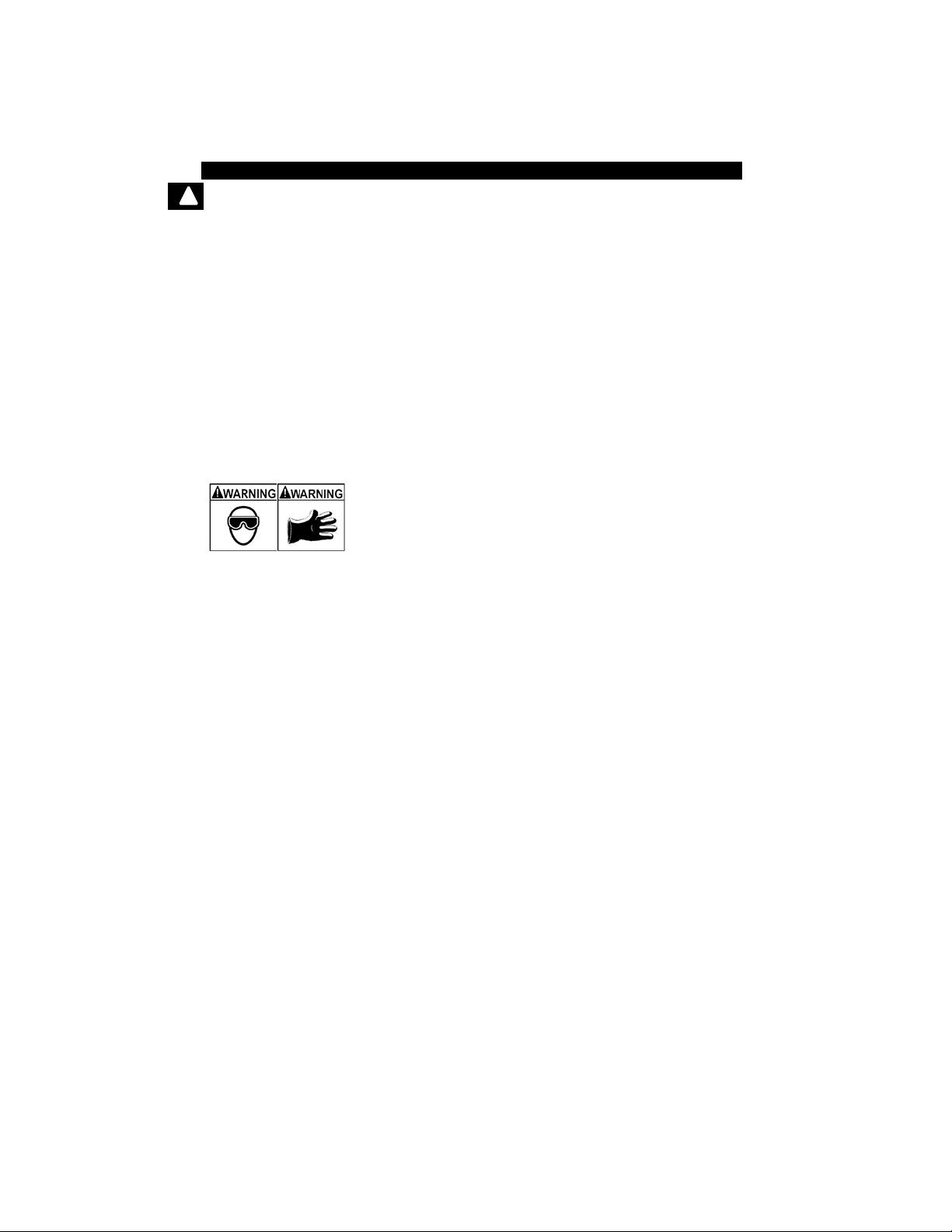
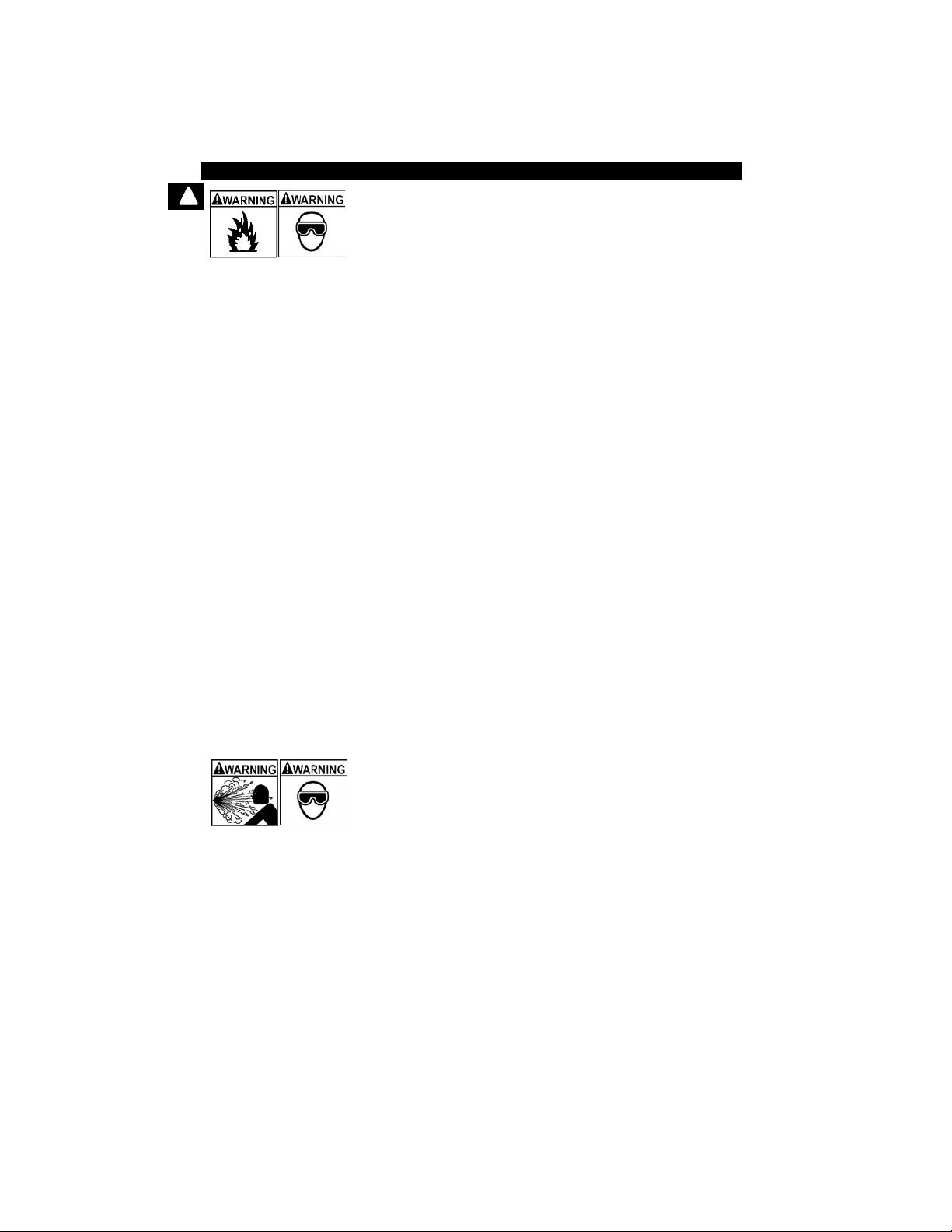
Engine systems can malfunction expelling fuel, oil
vapors, hot steam, hot toxic exhaust gases, acid,
refrigerant and other debris.
Safety goggles and protective gloves must be worn
by the operator and any byst anders. Even if everyday
eyeglasses have impact resistant lenses, they are
NOT safety glasses.
Engine systems that malfunction can cause injury.
• • • • • • • • • • • • • • • • • • • • • • • • • • • • • • • • • • • • • • • • • • • • • • • • • • • • • Safety – iii
Safety Precautions
!
Important Safety Messages
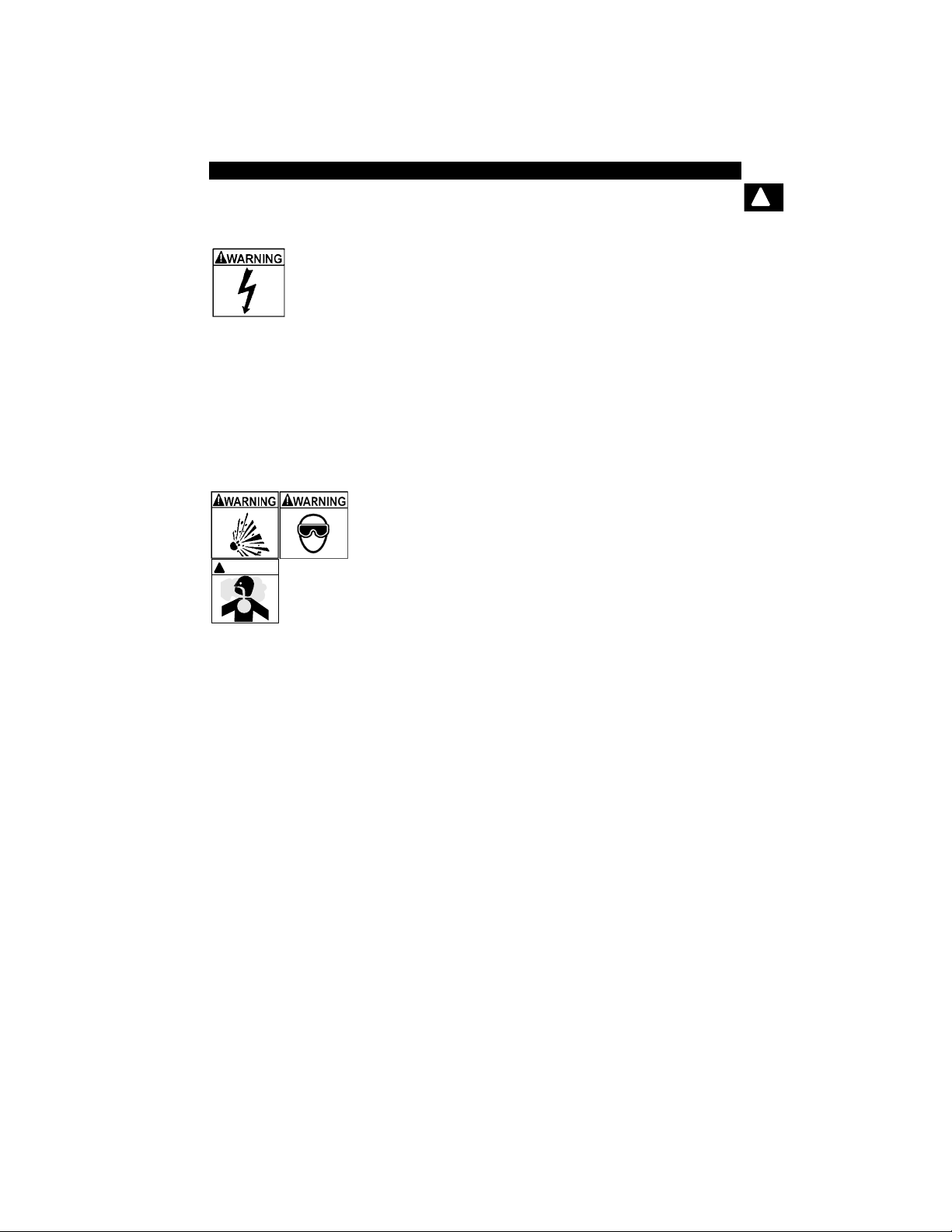
Risk of electric shock.
•Do not exceed voltage limits between inputs
indicated in the Specifications.
•Use extreme caution when working with circuits tha t
have voltage greater than 60 volts DC or 24 volts
AC.
Electric shock can cause injury.
Risk of explosion.
•Safety goggles and protective clothing must be
worn by the operator and any bystanders.
- Even if everyday glasses have impact resistant
lenses, they are NOT safety glasses, and may not
provide adequate protection.
•Do not use this scan tool in environments wher e
explosive vapors may collect. These areas include:
- below-ground pits.
- confined areas.
- areas that are less than 18 inches above floor.
•Use this Scan Tool in locations with mechanical
ventilation providing at least 4 air changes per hour .
•Flammable fuel and vapors can ignite.
•Do not smoke, strike a match, or cause a spark in
the vicinity of the battery. Battery gases can ignite.
!
WARNING

Safety Precautions
Safety – iv • • • • • • • • • • • • • • • • • • • • • • • • • • • • • • • • • • • • • • • • • • • • • • • • • • • •
!
•Avoid making an ac cidental connection between the
battery terminals. Do not place uninsulated metal
tools on the battery.
•When removing battery cables, remove the ground
cable first.
•Avoid sparks when connecting or disconnecting
power leads to the battery.
•Make sure ignition is off, headlights and other
accessories are off and vehicle doors are closed
before disconnecting the battery cables.
-
This also helps prevent damage to on-board computer sys-
tems.
•Always disconnect the battery ground connections
before servicing electrical system components.
Explosion can cause injury.
Risk of poisoning.
•Use this Scan Tool in locations with mechanical
ventilation providing at least 4 air changes per hour .
Engine exhaust contains odorless gas which can be
lethal.
•Route the exhaust outside wh ile testing with the
engine running.
Poisoning can result in death or serious injury.
!
WARNING

• • • • • • • • • • • • • • • • • • • • • • • • • • • • • • • • • • • • • • • • • • • • • • • • • • • • • Safety – v
Safety Precautions
!
Battery acid is a highly corrosive sulfuric acid.
•Safety goggles and protective gloves must be worn
by the operator and any bystanders.
- Even if your everyday glasses have impact resistant
lenses, they are NOT safety glasses, and may not
provide adequate protection.
•Make sure someone can hear you or is c lose enough
to provide aid when working near a battery.
•Have plenty of fresh water and soap nearby.
- If battery acid contacts skin, clothing, or eyes, flush
exposed area with soap and water for 10 minutes.
Seek medical help.
•Do not touch eyes while working near battery.
Battery acid can burn eyes and skin.
!
WARNING
Safety Precautions
Safety – vi • • • • • • • • • • • • • • • • • • • • • • • • • • • • • • • • • • • • • • • • • • • • • • • • • • • •
!
Risk of fire.
•Safety goggles and protective clothing must be
worn by the operator and any bystanders.
- Even if your everyday glasses have impact resistant
lenses, they are NOT safety glasses, and may not
provide adequate protection.
•Do not position your head directly in front of or over
the throttle body.
•Do not pour gasoline down the throttle body when
cranking or running the engine, when working with
fuel delivery systems or any open fuel line.
- Engine backfire can occur when the air cleaner is out
of position.
•Do not use fuel injector cleaning solvents when
performing diagnostic testing.
•Keep cigarettes, sparks , open flame and other
sources of ignition away from vehicle.
•Keep a dry chemical (Class B) fire extinguisher rated
for gasoline, chemical and electrical fires in work
area.
Fire can cause death or serious injury.
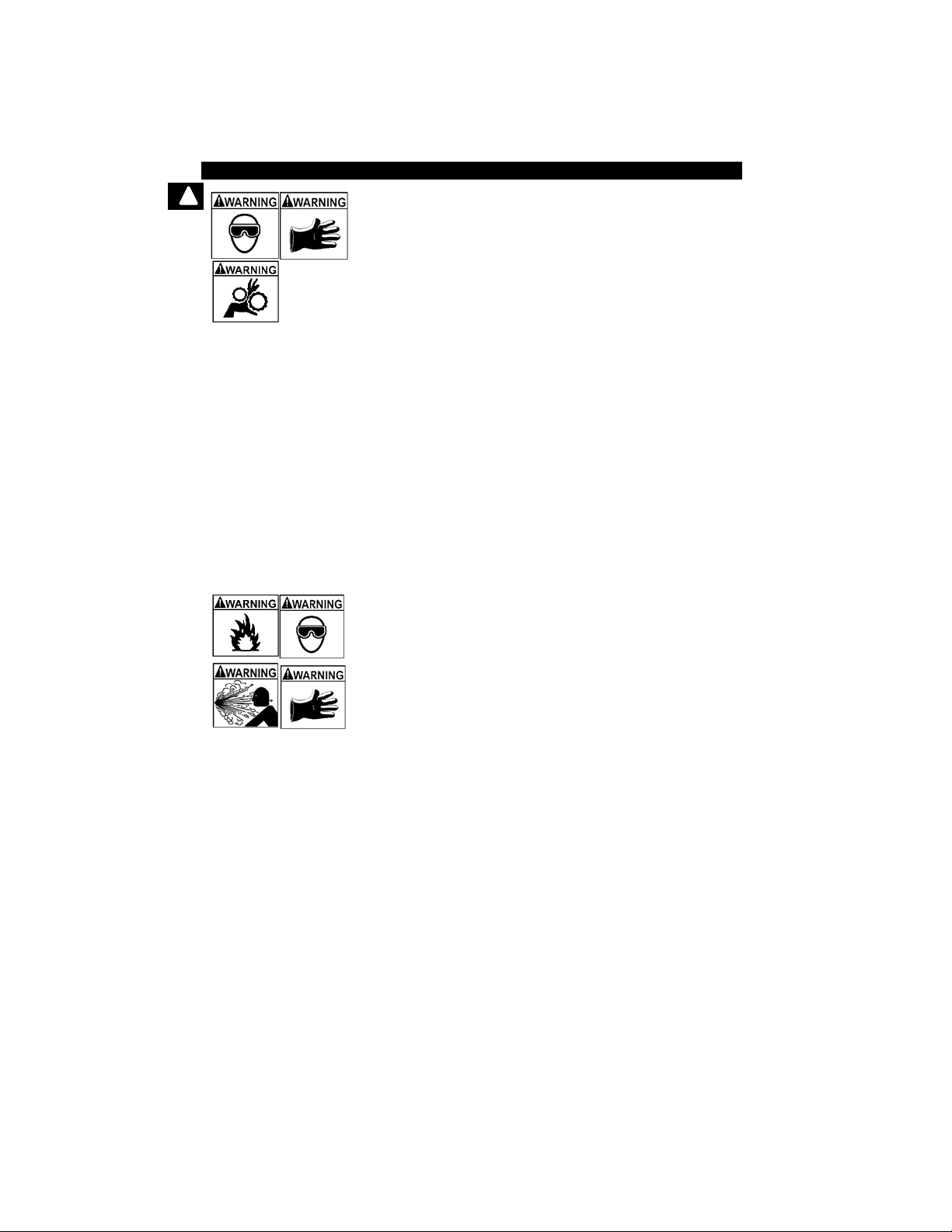
Risk of flying particles.
•Safety goggles and protective gloves must be worn
by the operator and any bystanders while using
electrical equipment.
- Electrical equipment or rotating engine parts can
cause flying particles.
- Even if your everyday glasses have impact resistant
lenses, they are NOT safety glasses, and may not
provide adequate protection.
Flying particles can cause eye injury.
• • • • • • • • • • • • • • • • • • • • • • • • • • • • • • • • • • • • • • • • • • • • • • • • • • • • Safety – vii
Safety Precautions
!
Risk of burns.
• Batteries can produce a short-circuit current high
enough to weld jewelry to metal.
- Remove jewelry such as rings, bracelets and
watches before working near batteries.
Short circuits can cause injury.
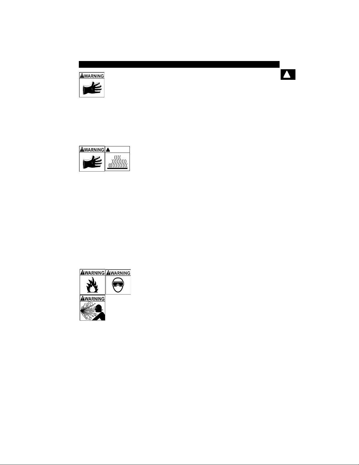
Risk of burns.
•Do not remove radiator cap unless engine is cold.
- Pressu rized engine coolant may be hot.
•Do not touch hot exhaust systems, manifolds,
engines, radiators, sample probe.
•Wear insulated gloves when handling hot engine
components.
•T ester leads can bec ome hot af ter extended tes ting
in close proximity to manifolds.
Hot components can cause injury.
Risk of expelling fuel, oil vapors, hot steam, hot toxic
exhaust gases, acid, refrigerant and other debris.
•Safety goggles and protective clothing must be
worn by the operator and any bystanders.
- Even if your everyday glasses have impact resistant
lenses, they are NOT safety glasses, and may not
provide adequate protection.
•Engine systems can malfunction, expelling fuel, oil
vapors, hot steam, hot toxic exhaust gases, acid,
refrigerant and other debris.
Fuel, oil vapors, hot steam, hot toxic exhaust gases,
acid, refrigerant and other debris can cause serious
injury.
!
WARNING
Safety Precautions
Safety – viii• • • • • • • • • • • • • • • • • • • • • • • • • • • • • • • • • • • • • • • • • • • • • • • • • • • •
!
Engine compartment contains ele ctrical connections and
hot or moving parts.
•Keep yourself, test leads, clothing and other object s
clear of electrical connections and hot or moving
engine parts.
•Do not wear watches, rings, or loose fitting clothing
when working in an engine compartment.
•Do not place tools or test equipment on fenders or
other places in engine compartment.
•Barriers are recommended to help identify danger
zones in test area.
•Prevent personnel from walking through test area.
Contacting electrical connections and hot or moving
parts can cause injury.
Risk of injury.
•The Scan Tool should be operated by qualified
personnel only.
•Use the scan tool only as described in the user’s
manual.
•Use only manufacturer’s recommended
attachments.
•Do not operate the Scan Tool with damaged cables.
•Do not operate the Scan T ool if it has been dropped
or damaged, until examined by a qualified service
representative.
Operation of the Scan Tool by anyone other than
qualified personnel may result in injury.
• • • • • • • • • • • • • • • • • • • • • • • • • • • • • • • • • • • • • • • • • • • • • • • • • • • • • Safety – ix
Safety Precautions
!
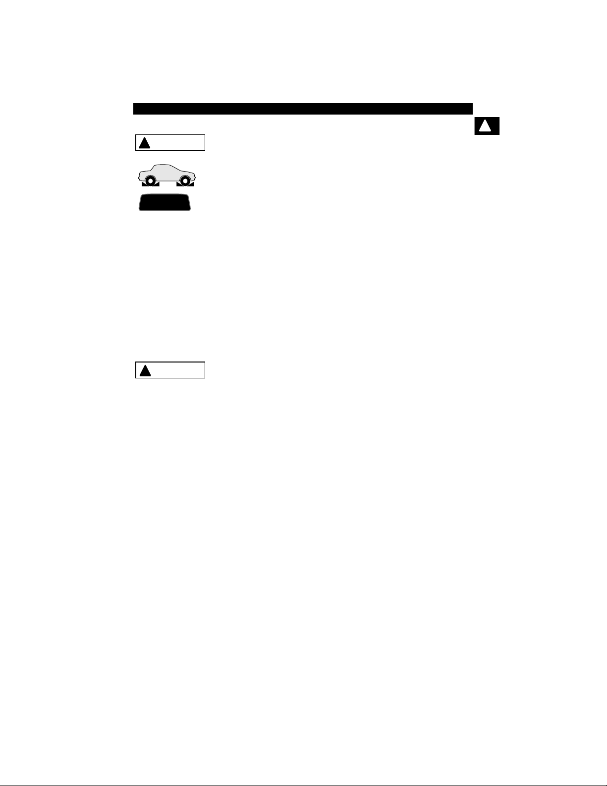
Risk of unexpected vehicle movement.
•Block drive wheels before performing a test with
engine running.
•Unless instructed otherwise:
- set parking brake
- put gear selector in neutral for manual transmissions
- put gear selector in park for automatic transmissions
- disconnect release mechanism on the automatic
parking brake release for testing and reconnect when
testing is completed.
• Do not leave a running engine unattended.
A moving vehicle can cause injury.
Risk of equipment or circuit damage.
•Unless specifically directed by manufacturer, make
sure ignition is off before connecting or
disconnecting connectors or any vehicle electrical
terminals.
•Do not create a short between batter y terminals with
a jumper wire or tools.
Improper equipment use can cause equipme nt or circu it
damage.
PR N DL2
!
WARNING
!
CAUTION

Safety Precautions
Safety – x • • • • • • • • • • • • • • • • • • • • • • • • • • • • • • • • • • • • • • • • • • • • • • • • • • • • •
!
Misdiagnosis may lead to incorrect or improper repair
and/or adjustment.
•Do not rely on erratic, questionable, or obviously
erroneous test information or results.
- If test information or results are erratic, questionable,
or obviously erroneous, make sure all connections
and data entry information are correct and test
procedures were performed correctly.
- If test information or results are still suspicious, do
not use them for diagnosis.
Improper repair and/or adjustment may cause vehicle o r
equipment damage or unsafe operation.
Some vehicles are equipped with air bags.
•Follow service manual warnings when working
around air bag components or wiring.
- If service manual instructions are not followed, an air
bag may deploy unexpectedly, resulting in injury.
- Note an air bag can still deploy several minutes after
ignition key is off (or even if vehicle battery is
disconnected) because of a special energy reserve
module.
An air bag opening can cause injury.
!
CAUTION
!
DANGER

• • • • • • • • • • • • • • • • • • • • • • • • • • • • • • • • • • • • • • • • • • • • • • • • • • • • • • • • • 1 – 1
1
Section 1 – Using This Manual
This manual contains instructions for the use and setup of your Scan T ool. A
table of contents and glossary are provided to make this manual easy to use.
Some of the information shown in text or illustrations is obtained using optional
equipment. A Sales Representative can determine option availability.
This section contains a list of conventions used.
Safety Messages
Refer to Safety Precautions on page Safety - i.
Check Note
A check note provides additional information about the subject in the preceding
paragraph.
Example:
✓ English is the default measurement unit.
Equipment Tips and Lists
Equipment tips and lists provide information that applies to specific equipment.
Each tip is introduced by this icon
❒ for easy identification.
Example:
❒ Observe all vehicle and/or equipment manufacturer’s cautions and
warnings when testing with the Sca n Tool.
Equipment Damage
Situations arise during testing that could damage the vehicle or the test
equipment. The word IMPORTANT signals these situations.
Example:
Failure to follow these instructions could damage the Scan Tool.
IMPORTANT

Using This Manual
1 – 2 • • • • • • • • • • • • • • • • • • • • • • • • • • • • • • • • • • • • • • • • • • • • • • • • • • • • • • • •
1
Functions and Selections
Diagnostic and tool functions performed by the Scan Tool are highlighted in
bold.
Example:
The View Data function allows you to view the vehicle’s parameter identification
(PID) data in real time.
Menus
The menus on the Scan T ool display are referenced in the procedures and are
highlighted in bold-italic text.
Example:
When the OBDII Function List menu displays, the Scan Tool is ready for use.
Questions and Responses
Messages and user responses are CAPITALIZED.
Example:
The Scan Tool displays the pending DTCs or a message stating SYSTEM
PASS: NO FAULT DETECTED.
Manual References
Used to reference other sections of the manual. References include the Title
and page number (section-page).
Example:
For more information on DTCs, refer to “OBD II Diagnostic Trouble Codes
(DTCs)” on page 2-15
Screens
Certain help messages, information, and data that are displayed on the scan
tool are also shown in graphical text boxes. The screens are presented as
examples and may change as the software is updated.
Example:
Global OBD II
Domestic Vehicles
European Vehicles
Asian Vehicles
Review Data
Print Data
System Setup
Main Menu

• • • • • • • • • • • • • • • • • • • • • • • • • • • • • • • • • • • • • • • • • • • • • • • • • • • • • • • • • 2 – 1
2
Section 2 – Getting Started
Introduction
The Scan Tool was developed by experts in the automotive service
industry to help diagnose vehicles and assist in troubleshooting
procedures.
The Scan Tool monitors vehicle events and retrieves codes from the
vehicle’s control modules to help pinpoint problem areas.
All information, illustrations and specifications contained in this manual
are based on the latest information available from industr y so urces a t
the time of publication.
No warranty (expressed or implied) can be made for its accuracy or
completeness, nor is any responsibility assumed by the manufacturer
or anyone connected with it for loss or damages suffered through
reliance on any information contained in this manual or misuse of
accompanying product. The manufacturer reserves the right to make
changes at any time to this manual or accompanying product without
obligation to notify any person or organization of such changes.

Getting Started
2 – 2 • • • • • • • • • • • • • • • • • • • • • • • • • • • • • • • • • • • • • • • • • • • • • • • • • • • • • • • •
2
Using the CD
✓ The included CD is NOT required to operate the Scan Tool
✓ Install the CD application prior to connecting the Scan Tool to the
PC.
✓ Some of the items included on the CD are:
❒ Manuals included with Scan Tool
❒ DTC lookup software
❒ Scan Tool update software
❒ Adobe Acrobat Reader Installer
❒ Print Capture
❒ Other product information
✓ T o be able to use the included CD the PC must meet the following
minimum requirements:
❒ 486 PC
❒ 4 MB of RAM
❒ Microsoft Windows 98 SE, ME, 2000, and XP
❒ CD ROM Drive
❒ Adobe Acrobat Reader
❒ Internet Explorer 4.0 or newer
❒ Screen Resolution of 800 x 600
– If screen resolution is 800 x 600, in Display Properties, Settings
Tab, set Font Size to Small Fonts.

• • • • • • • • • • • • • • • • • • • • • • • • • • • • • • • • • • • • • • • • • • • • • • • • • • • • • • • • • 2 – 3
Getting Started
2
Installing Applications On Included CD
1. Close all programs on the computer.
2. Place the CD in CD-Drive.
✓ If CD does not start automatically;
❒ Select the Start button.
❒ Select Run...
❒ Enter “X:\Setup.htm” in Open Box on
Computer and select OK.
❒ “X” is the CD-ROM drive
letter on the computer.
3. Follow screen prompts on the computer to install the
applications.
Run
Start
Enter

Getting Started
2 – 4 • • • • • • • • • • • • • • • • • • • • • • • • • • • • • • • • • • • • • • • • • • • • • • • • • • • • • • • •
2
Vehicle Service Information
The following is a list of web sites and phone numbers where electronic
engine control (EEC) diagnostic information is available.
✓ Some manuals may be available at your local dealer, auto parts
stores or local public libraries.
Domestic Vehicles Web Site Phone Number
General Motors
Chevrolet www.chevrolet.com 1-800-551-4123
Pontiac www.pontiac.com 1-800-551-4123
Oldsmobile www.oldsmobile.com 1-800-551-4123
Buick www.buick.com 1-800-551-4123
Cadillac www.cadillac.com 1-800-333-4CAD
Saturn www.saturn.com 1-800-553-6000
Ford
Ford www.ford.com 1-800-392-3673
Lincoln www.lincoln.com 1-800-392-3673
Mercury www.mercury.com 1-800-392-3673
Chrysler
Chrysler www.chrysler.com 1-800-348-4696
Dodge www.dodge.com 1-800-348-4696
Plymouth Not Available 1-800-348-4696
Eagle Not Available 1-800-348-4696
European Vehicles
Audi www.audi.com 1-800-544-8021
Volkswagon www.vw.com 1-800-544-8021
BMW www.bmw.com 1-201-307-4000
MINI www.mini.com 1-201-307-4000
Jaguar www.jaguar.com 1-800-4-JAGUAR
Volvo www.volvo.com 1-800-458-1552
Mercedes-Benz www.mercedes-benz.com 1-800-367-6372
Land Rover www.landrover.com 1-800-637-6837
Porsche www.porsche.com 1-800-PORSCHE
Saab www.saab.com 1-800-955-9007
Asian Vehicles Web Site Phone Number
Acura www.acura.com 1-800-999-1009
Honda www.honda.com 1-800-999-1009
Lexus www.lexus.com 1-800-255-3987
Scion www.scion.com 1.866.70.SCION
Toyota www.toyota.com 1-800-GO-TOYOTA

• • • • • • • • • • • • • • • • • • • • • • • • • • • • • • • • • • • • • • • • • • • • • • • • • • • • • • • • • 2 – 5
Getting Started
2
Hyundai www.hyundai.com 1-800-633-5151
Infiniti www.infiniti.com 1-800-662-6200
Nissan www.nissanusa.com 1-800-nissan1
Kia www.kia.com 1-800-333-4542
Mazda www.mazda.com 1-800-222-5500
Daewoo www.daewoo.com 1-822-759-2114
Subaru www.subaru.com 1-800-SUBARU3
Isuzu www.isuzu.com 1-800-255-6727
Geo Not Available Not Available
Mitsubishi www.mitsubishi.com 1-888-MITSU2004
Suzuki www.suzukiauto.com 1-800-934-0934
Other Manuals
Chilton Book Company www.chiltonsonline.com 1-800-347-7707
Haynes Publications www.haynes.com 1-800-242-4637
Bentley Publishers ‘ www.bentleypublishers.com 1-800-423-4595
Repair Information Programs
Mitchell www.mitchell1.com 1-888-724-6742
ALLDATA www.alldata.com 1-800-697-2533
Suitable Manual Titles
Diagnostic Service Manuals
PowerTrain Codes and Oxygen Sensors
Automotive Emission Control Manual
Fuel Injection
Automotive Electrical Manual
Automotive Electrics and Electronics
Automotive Sensors
Electronic Transmission Control
Emission Control Technology
Engine Management
or similar titles...

Getting Started
2 – 6 • • • • • • • • • • • • • • • • • • • • • • • • • • • • • • • • • • • • • • • • • • • • • • • • • • • • • • • •
2
Introduction to On-Board Diagnostics
OBD I
The original on-board diagnostics (OBD I) lacked consistency in
communication and interface while allowing different interpretations
among vehicle manufacturers. Ford and Chrysler used different types
of engine control computers and data link connectors ( DLCs), and GM
varied the trouble codes and communication protocols from
year-to-year.
OBD II
On-board diagnostics version II (OBD II) is a system that the Society of
Automotive Engineers (SAE) developed to standardize automotive
electronic diagnosis.
Beginning in 1996, most new vehicles sold in the United States were
fully OBD II compliant.
✓ Technicians can now use the same tool to test any OBD II
compliant vehicle without special adapters. SAE established
guidelines that provide:
❒ A universal connector, called the DLC, with dedicated pin
assignments.
❒ A standard location for the DLC, visible under the dash on driver’s
side.
❒ A standard list of diagnostic trouble codes (DTCs) used by all
manufacturers.
❒ A standard list of parameter identification (PID) data used by all
manufacturers.
❒ Ability for vehicle systems to record operating conditions when a
fault occurs.
❒ Expanded diagnostic capabilities that records a code whenever a
condition occurs that affects vehicle emissions.
❒ Ability to clear stored codes from the vehicle’s memory with a
Scan Tool.

• • • • • • • • • • • • • • • • • • • • • • • • • • • • • • • • • • • • • • • • • • • • • • • • • • • • • • • • • 2 – 7
Getting Started
2
SAE Publications
SAE has published hundreds of pages of text defining a standard
communication protocol that establishes hardware, software, and
circuit parameters of OBD II systems. Unfortunately, vehicle
manufacturers have different interpret ations of this standard
communications protocol. As a result, the generic OBD II
communications scheme varies, depending on the vehicle. SAE
publishes recommendations, not laws, but the Environmental
Protection Agency (EP A) a nd California Air Resources Bo ard (CARB)
made many of SAE’s recommendations legal requirements that vehicle
manufacturers were required to phase in over a three-year period.
Beginning in 1994, vehicles with a new engine management comp uter
( about 10% of each manufacturers fleet ) were supposed to comply
with OBD II standards. For 1995, OBD II systems were to appear on
about 40% of the new vehicles sold in the United S tates. Some of the
1994-1995 OBD II systems were not fully compliant, so th e Government
granted waivers to give manufacturers time to fine-tune their systems.
Beginning in 1996, most of the new vehicles sold in the United States
were fully OBD II compliant.
The tables below highlight changes for GM, Ford , and Chrysler. If this
seems confusing, don’t worry . The Scan Tool makes it easy . Ba sed on
the vehicle identification (VIN) information selected during Scan Tool
setup, the vehicle is automatically recognized. All you have to do is
choose the correct adapter cable and jumper wires (if necessary).
Details on adapter cables and jumper wires may be found in Data LInk
Connector on page 2-9
.
GM On-Board Diagnostics
System Years Description
OBD I Control Module
1981–1995
Most vehicles used the 12-pin ALDL (A ssembly Line Data Link)
located under the dash on the driver side. Some 94-95 vehicles
used the 16-pin OBD II (J196 2) da ta link co nnector (DLC) , but
use the Historical application software. Refer to the vehicle’s
Vehicle Emission Control Information label.
OBD II Control Module
1994*-Present Complies with OBD II regulations and uses the J1962 DLC.
*
OBD II system is used on certain 1994 -1995 vehicles equ ipped w ith a 2.2L, 2.3L, 3 .8L, 4.3L or 5.7L
engines.

Getting Started
2 – 8 • • • • • • • • • • • • • • • • • • • • • • • • • • • • • • • • • • • • • • • • • • • • • • • • • • • • • • • •
2
Ford On-Board Diagnostics
System Long Name Years Description
MCU
Microprocessor Control Unit 1980 –1991
Used in police vehicles, containing carbureted
engines. Uses the MCU DLC.
EEC-IV
Electronic Engine Control,
Fourth generation
1984 –1995
Most Ford vehicles equipped with North
American engines. Uses the EEC-IV DLC.
MECS
Mazda Electronic Control
System
1988 –1995
Vehicles equipped with Mazda-sourced engines.
Uses MECS 6-pin and 17-pin DLCs.
EEC-V
Electronic Engine Control,
Fifth generation
1994* – present
Complies with OBD II regulations and uses the
OBD II J1962 DLC.
PTEC
Powertrain Electronic
Controller
2000 – present
Complies with OBD II regulations and uses the
OBD II J1962 DLC.
* EEC-V OBD II system used in 1994-1995 vehicles equipped with a 3.8L or 4.6L engine.
Chrysler On-Board Diagnostics
System Long Name Years Description
SMEC
Single Module Engine
Controller
1989–1990
Used a 6-pin Serial Communication Interface (SCI)
DLC and has bidirectional capability.
SBEC
Single Board Engine
Controller
1989*–1995
Used two types of DLCs: a 6-pin SCI and a 6-pin LH
series.
The first to allow a tool to reset the EMR light on trucks.
OBD II
PCM
OBD II Powertrain
Control Module
1995**– present
Complies with OBD II regulations and uses the OBD II
J1962 DLC.
JTEC
Jeep/Truck Engine
Controller
1996– present
Complies with OBD II regulations and uses the OBD II
J1962 DLC.
The JTEC system is used on light-duty trucks and
Jeeps
* In 1989, the SBEC system was installed in selected vehicles with 3.0L V6 engines .
** Some vehicles in 1995 were equipped with the OBD II PCM.
• • • • • • • • • • • • • • • • • • • • • • • • • • • • • • • • • • • • • • • • • • • • • • • • • • • • • • • • • 2 – 9
Getting Started
2
Data Link Connector (DLC)
The data link connector (DLC) allows the Scan Tool to communicate
with the vehicle’s computer(s). Before OBD II, manufacturers used
different DLC’s to communicate with the vehicle. use the proper DLC
adapter cable to connect the Scan T ool to the vehicle. Also, the vehicle’s
DLC may be found in several different places and have many dif ferent
configurations. The following describes the DLCs used by Ford, GM
and Chrysler . The DLC location and types for domestic vehicles can be
looked up in the charts in Appendix B - Data Link Connectors.
OBD II (J1962)
Beginning in 1996, vehicles sold in the United States use the J1962
(OBD II) DLC, a term taken from a physical and electrical specification
number assigned by the SAE (J1962). The DLC should be located
under the dashboard on the driver’s side of the vehicle. If the DLC is not
located under the dashboard as state d, a decal de scribing it s locatio n
should be attached to the dashboard in the ar ea the DLC should have
been located.
Because the OBD II J1962 connector has power and ground, you only
need a single cable connection to the tool for both power and tool
communications. Attach the OBD II adapter cable to the extender cable,
(both supplied with the tool) to connect the tool. Certain pins in the
connector are reserved.
.

Getting Started
2 – 10 • • • • • • • • • • • • • • • • • • • • • • • • • • • • • • • • • • • • • • • • • • • • • • • • • • • • • • •
2
Data Link Connector (DLC) Pins
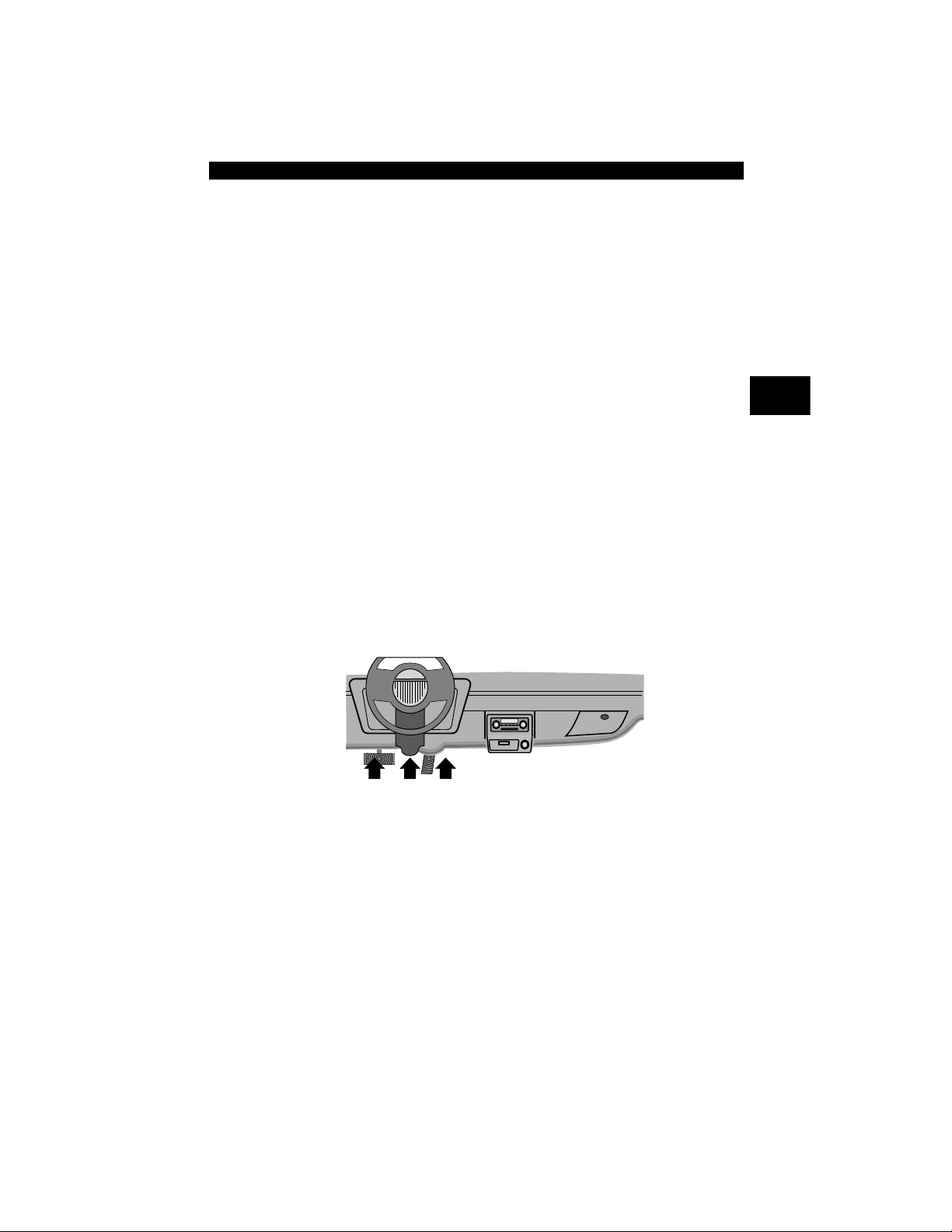
Ford Historic
Ford used three types of DLCs with their OBD I systems. Refer to
Appendix B - Data Lin k Connectors for the adapter cable needed for
your vehicle.
Use the cigarette lighter cable to provide power to the
Scan Tool for all systems.
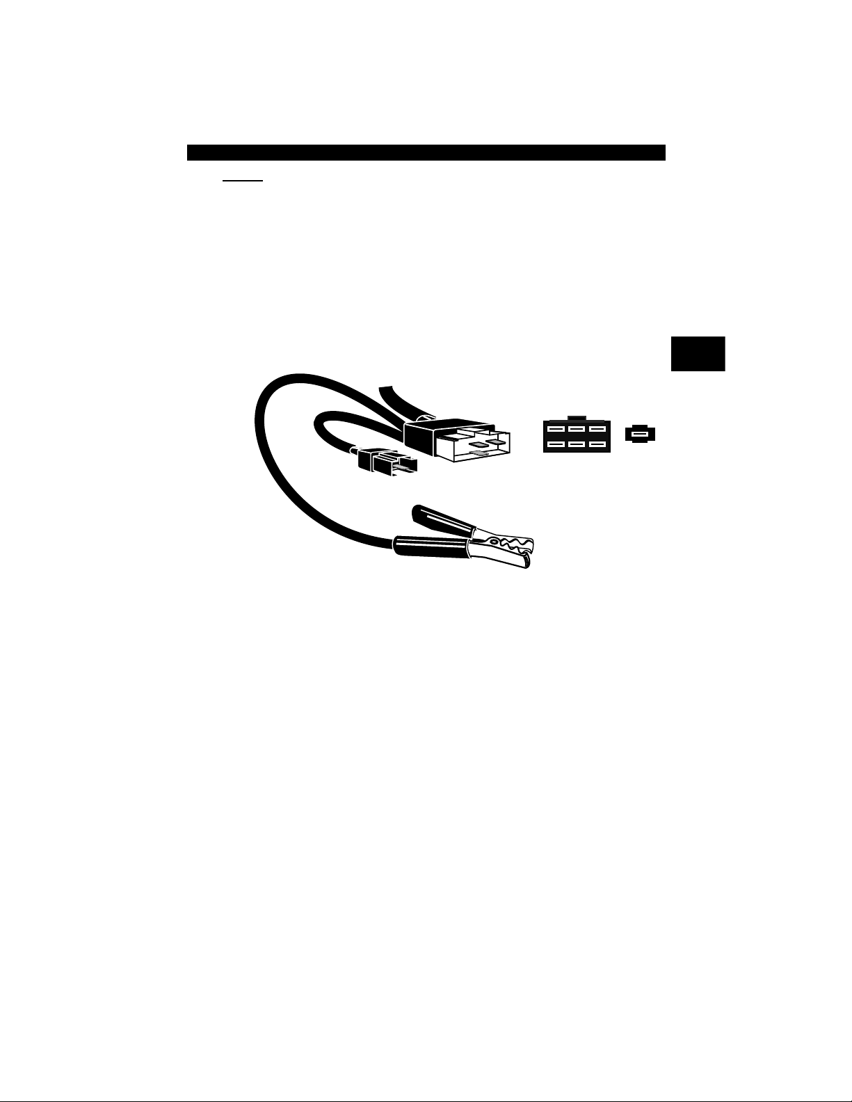
EEC-IV/MCU
The EEC-IV/MCU DLC is a large six-sided connector with a pigtail
connector . The pigt ail conne ctor is not used on MCU vehicles – leave
the pigtail unattached. The EEC-IV/MCU cable adapter is included with
the Scan Tool.
1 - Manufacturer Reserved
2 - J1850 Bus+
3 - Manufacturer Reserved
4 - Chassis Ground
5 - Signal Ground
6 - CAN High, J-2284
7 - K Line, ISO 9141-2 & ISO/DIS 14230-4
8 - Manufacturer Reserved
9 - Manufacturer Reserved
10 - J1850 Bus-
11 - Manufacturer Reserved
12 - Manufacturer Reserved
13 - Manufacturer Reserved
14 - CAN Low, J-2284
15 - L Line, ISO 9141-2 & ISO/DIS 14230-4
16 - Battery Power
1
9
8
16
IMPORTANT
Vehicle DLC
EEC-IV/MCU
Cable Adapter
EEC-IV/MCU
STI Pigtail
EEC-IV
only
To Scan
Tool
• • • • • • • • • • • • • • • • • • • • • • • • • • • • • • • • • • • • • • • • • • • • • • • • • • • • • • • • 2 – 11
Getting Started
2
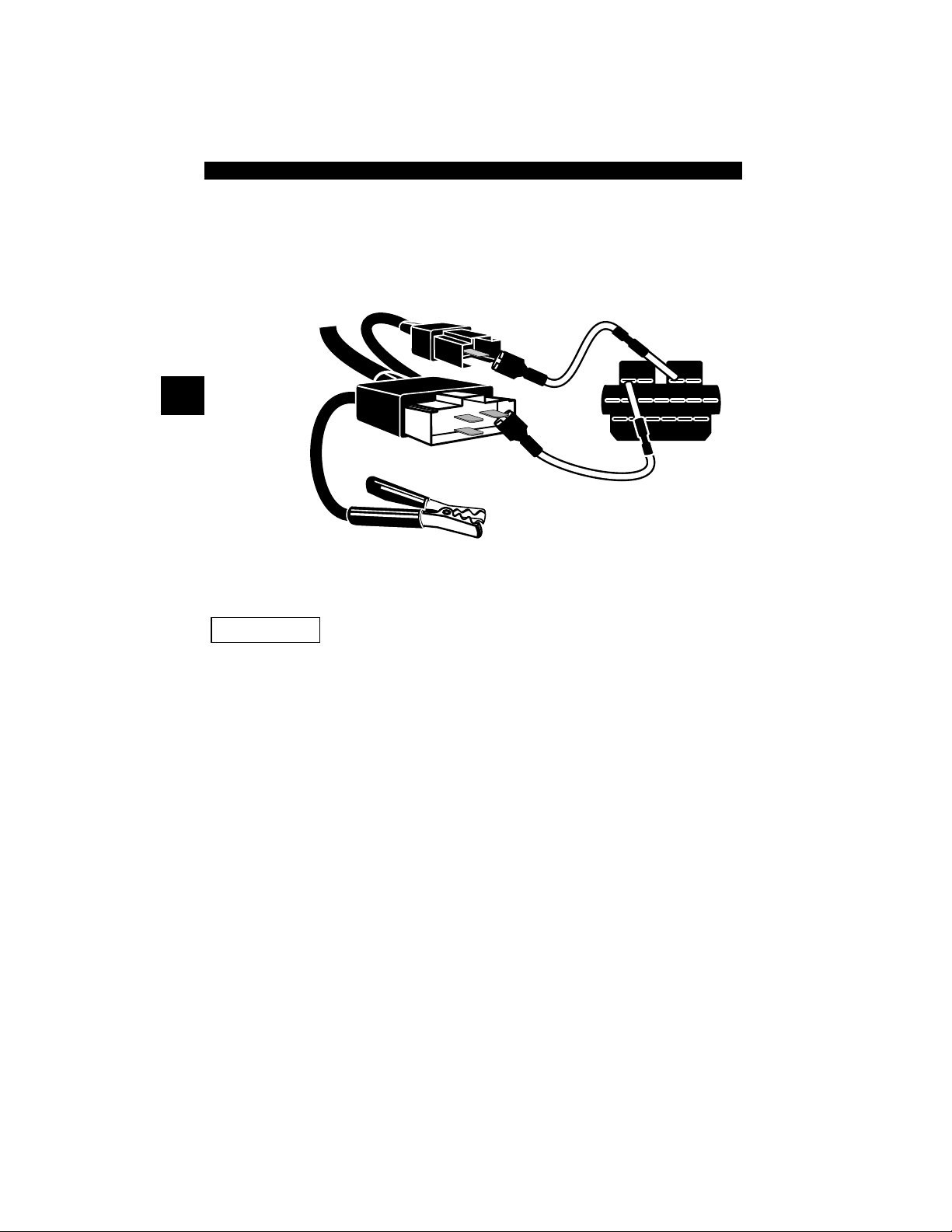
MECS
MECS vehicles (1988 –1995) use either a 6-pin (with pigtail) or a 17-pin
DLC. Use the MECS 6-pin adapter cable kit (CP9131) for both
configurations. The MECS adapter cable kit includes jumper wires to
connect to the MECS 17-pin DLC. The MECS adapter cable kit is
optional and must be purchased separate ly. Use the following diagrams
to connect the adapter cable.
6-Pin MECS
STI Pigtail
4
5
6
1
2
3
To Scan
Tool
6-Pin MECS
Clip to good
vehicle ground
Cable Adapter
Vehicle DLC
6-Pin MECS
Pigtail
P/N CP9131
Getting Started
2 – 12 • • • • • • • • • • • • • • • • • • • • • • • • • • • • • • • • • • • • • • • • • • • • • • • • • • • • • • •
2
17-Pin MECS
MECS Ford Probe
Certain Ford Probes have a WHITE TACH
CONNECTOR located very close to the 6-pin
self-test connector and bundled in the same wiring
harness. This is not the self-test input (STI) pigtail.
Connect the pigtail to the BLACK STI connector located fa rther back on
the wire harness. If the tool is connected to the WHITE tach connector ,
serious damage may result and may void warranty. Refer to the
illustration.
STI Pigtail
6-Pin MECS
STO
4
5
6
1
2
3
Clip to good
vehicle ground
Adapter Cable
Vehicle DLC
17-Pin MECS
To
Scan Tool
P/N CP9131
IMPORTANT
 Loading...