


CP9175
Table of contents
 Loading...
Next Generation
Do it Yourself AutoScanner
®
Performs diagnostics on
OBD II compliant vehicles
Instructions in English, Spanish, and French
Instrucciones en Inglés, Español, y Francés
Instructions en Anglais, Espagnol, et les Français
15825 Industrial Parkway
Cleveland Ohio 44135 USA (EUA)

Copyright Information
Copyright © 2005-2008 SPX Corporation
All rights reserved.
The information, specifications and illustrations in this
guide are based on the latest information available at the
time of printing. SPX Corporation reserves the right to
make changes at any time without notice.
Tool Information
Complete the following list.
Provide this information when
contacting customer support.
Serial No:
SW ID:
Refer to section 4.7 to get the Serial Number
(Serial No) and Software Identification (SW
ID.)
If you have questions or concerns Contact
Technical Support:
• Phone: 1-800-228-7667
• Web Site: www.actron.com

TOC
Table of Contents
Safety Precautions SF1
Safety Messages . . . . . . . . . . . . . . . . . . . . . . . . . . . . . . . . .SF-1
Signal Words Used: . . . . . . . . . . . . . . . . . . . . . . . . . . . SF-1
Type Styles Used: . . . . . . . . . . . . . . . . . . . . . . . . . . . . SF-2
Icons used: . . . . . . . . . . . . . . . . . . . . . . . . . . . . . . . . . . SF-2
Important Safety Messages . . . . . . . . . . . . . . . . . . . . . . . .SF-2
Getting Started 1
Vehicle Service Information . . . . . . . . . . . . . . . . . . . . . . . . . 1-1
Introduction to On-Board Diagnostics . . . . . . . . . . . . . . . . 1-3
SAE Publications . . . . . . . . . . . . . . . . . . . . . . . . . . . . . . .1-3
Data Link Connector (DLC) . . . . . . . . . . . . . . . . . . . . . . . . . 1-4
Diagnostic Trouble Codes (DTCs) . . . . . . . . . . . . . . . . . . . . 1-5
Using AutoScanner
®
2
The AutoScanner
®
Keypad Configuration . . . . . . . . . . . . . . 2-1
Specifications . . . . . . . . . . . . . . . . . . . . . . . . . . . . . . . . .2-2
Display . . . . . . . . . . . . . . . . . . . . . . . . . . . . . . . . . . . . . .2-3
Keypad . . . . . . . . . . . . . . . . . . . . . . . . . . . . . . . . . . . . . .2-3
Power . . . . . . . . . . . . . . . . . . . . . . . . . . . . . . . . . . . . . . . . . . . 2-4
Internal Battery 2-4
Vehicle Power 2-5
Diagnostic Trouble Codes and Data 3
Read Codes . . . . . . . . . . . . . . . . . . . . . . . . . . . . . . . . . . . . . . 3-1
Erase Codes . . . . . . . . . . . . . . . . . . . . . . . . . . . . . . . . . . . . . 3-3
MIL (Malfunction Indicator Lamp) Status . . . . . . . . . . . . . . 3-6
I/M Monitors (Emissions Systems) . . . . . . . . . . . . . . . . . . . 3-7
View Freeze Data . . . . . . . . . . . . . . . . . . . . . . . . . . . . . . . . . . 3-9
Review . . . . . . . . . . . . . . . . . . . . . . . . . . . . . . . . . . . . . . . . . 3-11
Code Lookup . . . . . . . . . . . . . . . . . . . . . . . . . . . . . . . . . . . . 3-12

TOC
System Setup / Test 4
System Setup . . . . . . . . . . . . . . . . . . . . . . . . . . . . . . . . . . . . 4-1
Adjusting Display Contrast . . . . . . . . . . . . . . . . . . . . . . 4-2
Language Setup . . . . . . . . . . . . . . . . . . . . . . . . . . . . . . . 4-3
Display Test . . . . . . . . . . . . . . . . . . . . . . . . . . . . . . . . . . 4-4
Keypad Test . . . . . . . . . . . . . . . . . . . . . . . . . . . . . . . . . . 4-5
Memory Test . . . . . . . . . . . . . . . . . . . . . . . . . . . . . . . . . 4-6
Tool Information . . . . . . . . . . . . . . . . . . . . . . . . . . . . . . 4-7
Program Mode . . . . . . . . . . . . . . . . . . . . . . . . . . . . . . . . 4-8
Troubleshooting 5
Error Messages . . . . . . . . . . . . . . . . . . . . . . . . . . . . . . . . . . 5-1
Tool Does Not Power Up . . . . . . . . . . . . . . . . . . . . . . . . . . . 5-1
Operating Error or Erroneous Data . . . . . . . . . . . . . . . . . . 5-2
Glossary . . . . . . . . . . . . . . . . . . . . . . . . . . . . . . . . . . . .A1
Global PID’s . . . . . . . . . . . . . . . . . . . . . . . . . . . . . . . . .B1
Warranty & Repair. . . . . . . . . . . . . . . . . . . . . . . . . . . . .B4

SF-1
Safety Precautions
For safety, read, understand and follow all safety messages and
instructions in manual and on test equipment before operating tool.
Always refer to and follow safety messages and test procedures
provided by manufacturer of vehicle and tools.
Safety messages below and throughout this manual are reminders to
use caution when using tool.
Safety Messages
Safety messages are provided to help prevent personal injury and
equipment damage.
Safety messages in this section of the manual have a signal word with
a 3 part message and, in some cases, an icon. The signal word
indicates the level of the hazard.
Signal Words Used:
Indicates a possible hazardous sit uation which, if
not avoided, will result in death or serious injury to
operator or bystanders.
Indicates a possible hazardous sit uation which, if
not avoided, could result in death or serious injury
to operator or bystanders.
Indicates a possible hazardous sit uation which, if
not avoided, may result in moderate or minor
injury to operator or bystanders.
Indicates a condition which, if not avoided, may
result in damage to test equipment or vehicle.
!
DANGER
!
WARNING
!
CAUTION
IMPORTANT
SF-2
Type Styles Used:
Normal type states hazard.
Bold type states how to avoid hazard.
Italic type states possible results of not avoiding hazard.
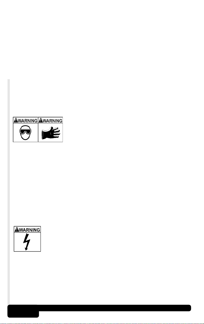
Icons used:
An icon, when present, gives a graphical description of possible
hazard.
Example:
Engine systems can malfunction spilling fuel,
oil vapors, hot steam, hot toxic exhaust
gases, acid, refrigerant and other debris.
• Wear safety goggles and protective gloves
- User and bystander
- Even if your everyday glasses have impact
resistant lenses, they may NOT be safety
glasses, and may not provide adequate
protection.
Engine systems that malfunction can cause injury.
Important Safety Messages
Risk of electric shock.
• Do not exceed voltage limits between inputs
indicated in “Specifications.”
• Use extreme caution when working with circuits
that have greater than 60 volts DC or 24 volts
AC.
Electric shock can cause injury.

SF-3
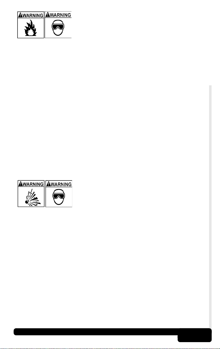
Risk of explosion.
• Wear safety goggles and protective clothing.
- User and bystander
- Even if your everyday glasses have impact
resistant lenses, they may NOT be safety
glasses, and may not provide adequate
protection.
• Do not use Tool in environments where
explosive vapors may collect.
- As in below-ground pits, confined areas, or
areas that are less than 18 inches above
floor.
• Use Tool in locations with mechanical
ventilation providing at least 4 air changes per
hour.
• Flammable fuel and vapors can ignite.
• Do not smoke, strike a match, or cause a spark in
vicinity of battery.
Battery gases can ignite.
• Avoid making accidental connection between
battery terminals.
- Do not place uninsulated metal tools on
battery.
• When removing battery cables, remove ground
cable first.
• Avoid sparks when connecting or disconnecting
power leads to battery.
• Make sure ignition is OFF , headlights and other
accessories are OFF and vehicle doors are
closed before disconnecting battery cables.
- This also helps prevent damage to on-board
computer systems.
• Always disconnect battery ground connections
before servicing electrical system components.
Explosion can cause injury.
!
WARNING

SF-4
Risk of poisoning.
• Use Tool in locations with mechanical
ventilation providing at least 4 air changes per
hour. Engine exhaust contains odorless lethal
gas.
• Route exhaust outside while testing with engine
running.
Poisoning can result in death or serious injury.
Battery acid is a highly corrosive sulfuric acid.
• Wear safety goggles and protective gloves.
- User and bystander
- Even if your everyday glasses have impact
resistant lenses, they may NOT be safety
glasses, and may not provide adequate
protection.
• Make sure someone can hear or is close enough
to provide aid when working near a battery.
• Have plenty of fresh water and soap nearby .
- If battery acid contacts skin, clothing, or
eyes, flush exposed area with soap and
water for 10 minutes.
- Seek medical help.
• Do not touch eyes while working near battery.
Battery acid can burn eyes and skin.
!
WAR NI N G
!
WARNING
SF-5
Risk of fire.
• Wear safety goggles and protective clothing.
- User and bystander
- Even if your everyday glasses have impact
resistant lenses, they may NOT be safety
glasses, and may not provide adequate
protection.
• Do not position head directly over or in front of
throttle body .
• Do not pour gasoline down throttle body when
cranking or running engine, when working with
fuel delivery systems or any open fuel line.
- Engine backfire can occur when air cleaner
is out of position.
• Do not use fuel injector cleaning solvents when
performing diagnostic testing.
• Keep cigarettes, sparks, open flame and other
sources of ignition away from vehicle.
• Keep a dry chemical (Class B) fire extinguisher
rated for gasoline, chemical and electrical fires
in work area.
Fire can cause death or serious injury.
Risk of flying particles.
• Wear safety goggles while using electrical
equipment.
- Electrical equipment or rotating engine parts
can cause flying particles.
- Even if your everyday glasses have impact
resistant lenses, they may NOT be safety
glasses, and may not provide adequate
protection.
Flying particles can cause eye injury.
SF-6
Risk of burns.
• Batteries can produce a short-circuit
current high enough to weld jewelry to
metal.
- Remove jewelry such as rings, bracelets
and watches before working near batteries.
Short circuits can cause injury.
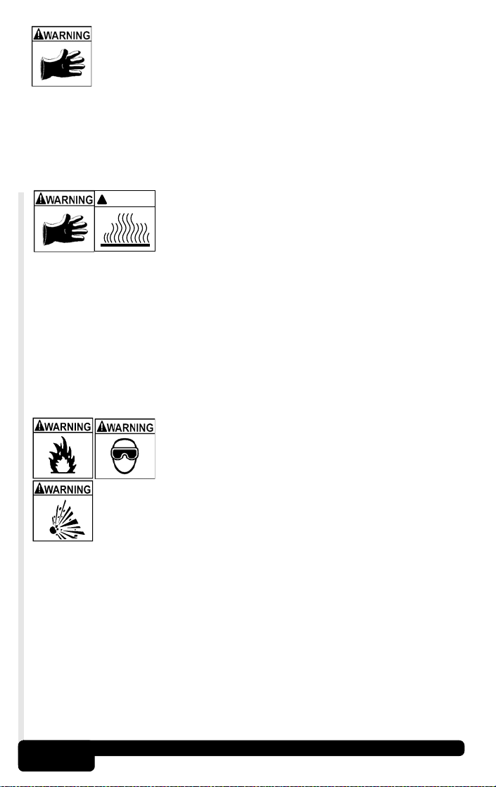
Risk of burns.
• Do not remove radiator cap unless engine is
cold.
- Pressurized engine coolant may be hot.
• Do not touch hot exhaust systems, manifolds,
engines, radiators, sample probe, etc.
• Wear insulated gloves when handling hot engine
components.
• Tester leads can become hot after extended
testing in close proximity to manifolds etc.
Hot components can cause injury.
Risk of spilling fuel, oil vapors, hot steam, hot
toxic exhaust gases, acid, refrigerant and
other debris.
• Wear safety goggles and protective clothing
- User and bystander
- Even if your everyday glasses have impact
resistant lenses, they may NOT be safety
glasses, and may not provide adequate
protection.
• E ngine systems can malfunction
- Expelling fuel, oil vapors, hot steam, hot
toxic exhaust gases, acid, refrigerant and
other debris.
Fuel, oil vapors, hot steam, hot toxic exhaust gases,
acid, refrigerant and other debris can cause serious
injury.
!
WARNING

SF-7
Engine compartment contains electrical
connections and hot or moving parts.
• Keep personnel, test leads, clothing and other
objects clear of electrical connections and hot or
moving engine parts.
• Do not wear watches, rings, or loose fitting
clothing when working in an engine
compartment.
• Do not place tools on fenders or other places in
engine compartment.
• To help identify danger zones in test areas us e
barriers.
• Prevent personnel from walking through test
area.
Contacting electrical connections and hot or moving
parts can cause injury.
Risk of injury.
• Only qualified personnel should operate tool.
• Use tool only as described in guide.
• Do not operate tool with damaged cords.
• Do not operate tool if dropped or damaged, until
examined by a qualified service representative.
Operation of tool by anyone other than qualified
personnel may result in injury.
Risk of unexpected vehicle movement.
• Block drive wheels before performing a test with
engine running.
• Unless instructed otherwise:
- set parking brake
- put gear selector in neutral for standard
transmissions
- put gear selector in park for automatic
transmissions
- disconnect release mechanism on
automatic parking brake release, for testing
and reconnect when testing is completed.
• Do not leave engine running unattended.
A moving vehicle can cause injury.
PRN D L 2
!
WARNING
SF-8
Risk of equipment or circuit damage.
• Unless specifically directed by manufacturer,
make sure ignition is OFF before conn ecti ng or
disconnecting connectors or any vehicle
electrical terminals.
• Do not create a short between battery terminals
with a jumper wire or tools.
Improper equipment use can cause equipment or
circuit damage.
Misdiagnosis may lead to incorrect or
improper repair and/or adjustment.
• Do not rely on erratic, questionable, or obviously
erroneous test information or results.
- Make sure all connections and data entry
information are correct and test procedures
performed right, if test information or results
are erratic, questionable, or obviously
erroneous.
- If test information or results are still
suspicious, do not use them for diagnosis.
Improper repair and/or adjustment may cause
vehicle or equipment damage or unsafe operation.
Some vehicles are equipped with air bags.
• Follow vehicle service manual’s warnings when
working around air bag components or wiring.
- If service manual instructions are not
followed, air bag may open unexpectedly,
resulting in injury.
- Note air bag can still open up several
minutes after ignition key is off (or if vehicle
battery is disconnected) because of a
special energy reserve module.
An air bag opening can cause injury.
!
CAUTION
!
CAUTION
!
DANGER

Getting Started
1-1
Section 1 – Getting Started
The Global OBD II AutoScanner
®
was developed by experts in
the automotive service industry to help dia gn o se ve hic les an d
assist in troubleshooting procedures.
AutoScanner
®
monitors vehicle events and retrieves codes fro m
vehicle’s control module to help pinpoint problem area s.
All information, illustrations and specifications contained in this
manual are based on the latest information available from
industry sources at the time of publication.
No warranty (expressed or implied) can be made for it s accuracy
or completeness, nor is any responsibility assumed by the
manufacturer or anyone connected with it for loss or dam ages
suffered through reliance on any informa tion contained in this
guide or misuse of accompanying product. The manufacturer
reserves the right to make changes at any time to this guide or
accompanying product without obligation to notify any person or
organization of such changes.
Vehicle Service Information
The following is a list of web sites and phone numbers where
electronic engine control diagnostic information is available.
✓ Some manuals may be available at your local deale r , auto
parts stores or local public libraries

1-2
Getting Started
Web Site Phone Number
Chevrolet www.chevrolet.com 1-800-551-4123
Pontiac www.pontiac.com 1-800-551-4123
Oldsmobile www.oldsmobile.com 1-800-551-4123
Buick www.buick.com 1-800-551-4123
Cadillac www.cadillac.com 1-800-333-4CAD
Saturn www.saturn.com 1-800-553-6000
Ford www.ford.com 1-800-392-3673
Lincoln www.lincoln.com 1-800-392-3673
Mercury www.mercury.com 1-800-392-3673
Chrysler www.chrysler.com 1-800-348-4696
Dodge www.dodge.com 1-800-348-4696
Plymouth Not Available 1-800-348-4696
Eagle Not Available 1-800-348-4696
Audi www.audi.com 1-800-544-8021
Volkswagon www.vw.com 1-800-544-8021
BMW www.bmw.com 1-201-307-4000
MINI www.mini.com 1-201-307-4000
Jaguar www.jaguar.com 1-800-4-JAGUAR
Volvo www.volvo.com 1-800-458-1552
Mercedes www.mercedes-benz.com 1-800-367-6372
Land Rover www.landrover.com 1-800-637-6837
Porsche www.porsche.com 1-800-PORSCHE
Saab www.saab.com 1-800-955-9007
Acura www.acura.com 1-800-999-1009
Honda www.honda.com 1-800-999-1009
Lexus www.lexus.com 1-800-255-3987
Scion www.scion.com 1.866.70.SCION
Toyota www.toyota.com 1-800-GO-TOYOTA
Hyundai www.hyundai.com 1-800-633-5151
Infiniti www.infiniti.com 1-800-662-6200
Nissian www.nissianusa.com 1-800-nissian1
Kia www.kia.com 1-800-333-4542
Mazda www.mazda.com 1-800-222-5500
Daewoo www.daewoo.com 1-822-759-2114
Subaru www.subaru.com 1-800-SUBARU3
Isuzu www.isuzu.com 1-800-255-6727
Geo Not Available Not Available
Mitsubishi www.mitsubishi.com 1-888-MITSU2004
Suzuki www.suzukiauto.com 1-800-934-0934
Chilton Book Company www.chiltonsonline.com 1-800-347-7707
Haynes Publications www.haynes.com 1-800-242-4637
Bentley Publishers www.bentleypublishers.com 1-800-423-4595
Mitchell www.mitchell1.com 1-888-724-6742
ALLDATA www.alldata.com 1-800-697-2533
European Vehicles
Asian Vehicles
Other Manuals
Suitable Manual
Titles
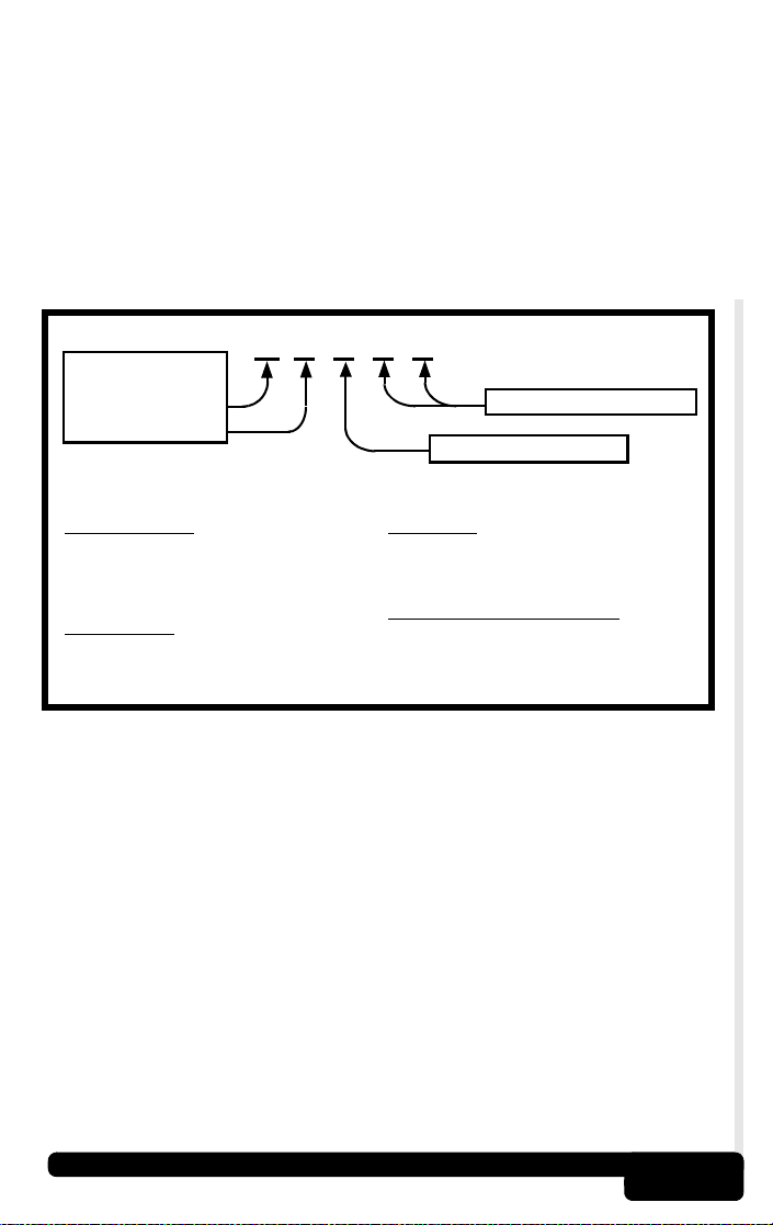
Repair Information
Programs
General
Motors
Ford
Chrysler
Domestic
Vehicles
or similar titles...
“Automotive Electrics and Electronics”
“Automotive Sensors”
“Electronic Transmission Control”
“Emission Control Technology
“Fuel Injection”
“Automotive Electrical Manual”
“Diagnostic Service Manuals”
“Engine Management”
“PowerTrain Codes and Oxygen Sensors”
“Automotive Emission Control Manual”

Getting Started
1-3
Introduction to On-Board Diagnostics
OBD II (On-Board Diagnostics version II) is a system that the
Society of Automotive Engineers (SAE) developed to
standardize automotive electronic diagnosis.
Beginning in 1996, most new vehicles sold in the USA were
OBD II compliant.
✓ T echn icians now can use the same tool to test any OBD
II compliant vehicle without special adapters. SAE
established guidelines that provide:
❒ A universal connector, called the Data Link Connector
(DLC), with dedicated pin assignments.
❒ A standard location for the Data Link Connector (DLC),
visible under the dash on driver’s side.
❒ A standard list of diagnostic trouble codes (DTCs) used
by all manufacturers.
❒ A standard list of parameter identification (PID) data
used by all manufacturers.
❒ Ability for vehicle systems to record operating conditions
when fault occurs.
❒ Expanded diagnostic capabilities that records a code
whenever a condition occurs that affects vehicle
emissions.
❒ Ability to clear stored codes from vehicles memory with
Tool.
SAE Publications
SAE has published hundreds of pages of text defining a
standard communication protocol that est ablishes hardware,
software, and circuit parameters of OBD II systems.
• SAE publishes recommendations, not laws, but the
Environmental Protection Agency (EPA) and California Air
Resources Board (CARB) made many of SAE’s
recommendations legal requirements.
1-4
Getting Started
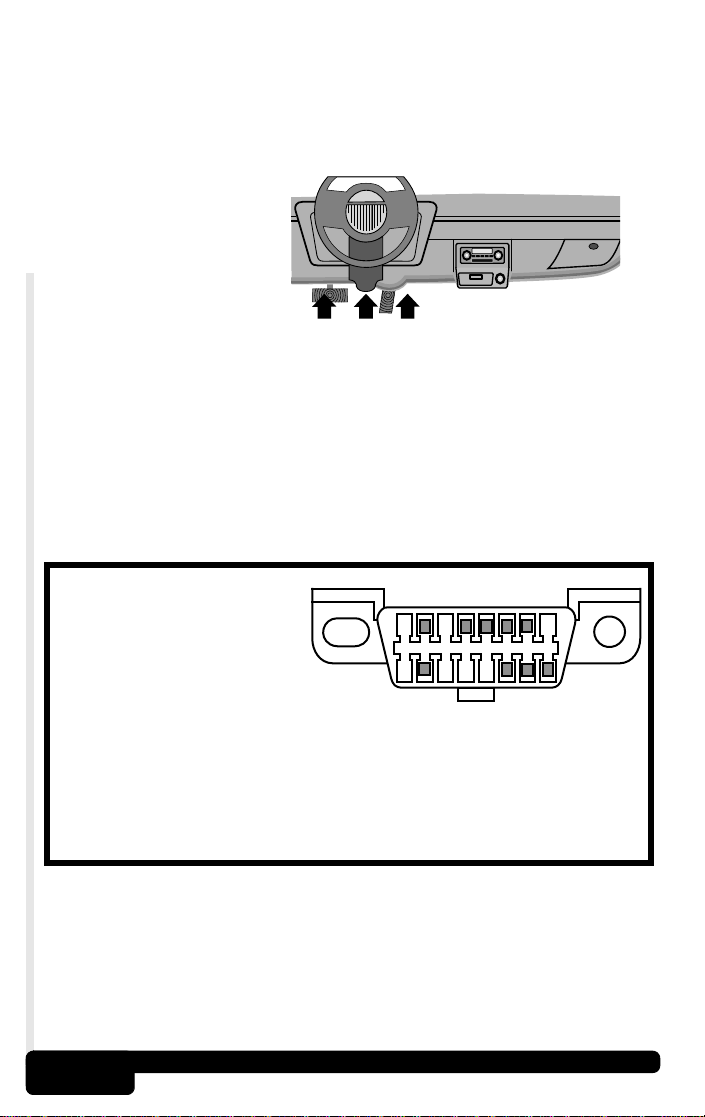
Data Link Connector (DLC)
The AutoScanner
®
uses a Data Link Connector (DLC) to
communicate with the vehicle’s control module.
✓ Data Link
Connector
Location.
❒ Under
dashboard on
driver side of
vehicle.
❒ If Data Link
Connector is
not located
under dashboard, a label should be there telling where
the connector can be found.
Data Link Connector (DLC) Pins
1 - Manufacturer Reserved
2 - J1850 Bus+
3 - Manufacturer Reserved
4 - Chassis Ground
5 - Signal Ground
6 - CAN High, J-2284
7 - K Line, ISO 9141-2 & ISO/DIS 14230-4
8 - Manufacturer Reserved
9 - Manufacturer Reserved
10 - J1850 Bus-
11 - Manufacturer Reserved
12 - Manufacturer Reserved
13 - Manufacturer Reserved
14 - CAN Low, J-2284
15 - L Line, ISO 9141-2 & ISO/DIS
14230-4
1
9
8
16
Getting Started
1-5
Diagnostic Trouble Codes (DTCs)
✓ Diagnostic Trouble Codes help determin e the cause of a
problem or problems with a vehicle.
❒ Diagnostic Trouble Codes (DTCs) consist of a five-digit
alphanumeric code.
❒ The Diagnostic Trouble Codes format and general code
types are shown below.
Example:
P0101 - Mass or Volume Air Flow Circuit Range/Performance Problem
P 0 1 0 1
Vehicle Specific System
Powertrain Codes
P0xxx - Generic (SAE)
P1xxx - Manufacturer Specific
P2xxx - Generic (SAE)
P30xx-P33xx - Manufacturer Specific
P34xx-P39xx - Generic (SAE)
Chassis Codes
C0xxx - Generic (SAE)
C1xxx - Manufacturer Specific
C2xxx - Manufacturer Specific
C3xxx - Generic (SAE)
Body Codes
B0xxx - Generic (SAE)
B1xxx - Manufacturer Specific
B2xxx - Manufacturer Specific
B3xxx - Generic (SAE)
Network Communication Codes
U0xxx - Generic (SAE)
U1xxx - Manufacturer Specific
U2xxx - Manufacturer Specific
U3xxx - Generic (SAE)
Specific Fault Designation
Bx - Body
Cx - Chassis
Px - Powertrain
Ux - Network Comm.
x = 0, 1, 2 or 3

1-6
Getting Started
Within each category (Powertrain, Chassis, Body and
Network) of Diagnostic Trouble Codes there are assigned
ranges for different vehicle systems.
✓ J2012 and ISO 15031-6 are standards for all Diagnostic
Trouble Codes, establishe d by the SAE, International
Organization for Standardization (ISO) and other
governing bodies.
❒ Codes and de fin itio ns assig ned by these specifications
are known as Generic OBD II codes.
❒ OBD II requires compliance to these standards, for all
cars, light trucks, APVs, MPVs, and SUVs sold in the
U.S.
❒ Codes not reserved by SAE are manufacturer reserved
and referred to as Manufacturer Specific Codes.
Lower Upper Assigned DTC System
P0000 P00FF Fuel Air Metering Auxiliary Emission Controls
P0100 P02FF Fuel Air Metering
P0300 P03FF Ignition System or Misfire
P0400 P04FF Auxiliary Emission Controls
P0500 P05FF Vehicle Speed Idle Control Auxiliary Inputs
P0600 P06FF Computer and Auxiliary Outputs
P0700 P09FF Transmission
P0A00 P0AFF Hybrid Propulsion
P1000 P10FF Manufacturer Control Fuel & Air Metering, Auxiliary Emission Controls
P1100 P12FF Manufacturer Control Fuel & Air Metering
P1300 P13FF Manufacturer Control Ignition System or Misfire
P1400 P14FF Manufacturer Control Auxiliary emission Controls
P1500 P15FF Manufacturer Cntrl Veh.Spd. Idle Speed Control Auxiliary Inputs
P1600 P16FF Manufacturer Control Auxiliary Inputs Auxiliary Outputs
P1700 P19FF Manufacturer Control Transmission
P2000 P22FF Fuel Air Metering Auxiliary emission Controls
P2300 P23FF Ignition System or Misfire
P2400 P24FF Auxiliary Emission Controls
P2500 P25FF Auxiliary Inputs
P2600 P26FF Computer and Auxiliary Outputs
P2700 P27FF Transmission
P2900 P32FF Fuel Air Metering Auxiliary Emission Controls
P3300 P33FF Ignition System
P3400 P34FF Cylinder Deactivation
U0000 U00FF Network Electrical
U0100 U02FF Network Communication
U0300 U03FF Network Software
U0400 U04FF Network Data

AutoScanner® Specifications & Power Information
2-1
Section 2 – AutoScanner
®
Specifications & Power
Information
The AutoScanner
®
Keypad Configu-
ration
1 LCD Display – 128 x 64 graphic
display with contrast adjust.
2
UP
arrow key – moves UP
through functions and picks YES
on questions requiring a yes or no
answer.
3
ENTER
key – selects displayed
items.
4 DOWN arrow key – moves
DOWN through functions and
picks NO on questions requiring a
yes or no answer.
5
BACK
key – usually returns to
previous screen or DIAGNOSTIC
MENU and cancels the prior
selection.
6 ERASE hot key – used to run
the Erase function.
7
POWER
key – turns power ON
or OFF when disconnected from
vehicle.
8 OBD II Cable – provides
connection for vehicle interface.
9 Serial Port – gives a way to get
upgrades for the AutoScanner
®
.
10 Serial Number Plate – (On Back)
shows serial number.
11 Battery Compartment –
provides power to AutoScanner
®
for upgrading or reviewing codes
off-vehicle.
1
2
3
4
5
6
7
8
9
on top
11
10

2-2
AutoScanner® Specifications & Power Information
Specifications
Display: 128 x 64 pixel display with contrast adjust.
Operating Temperature: 0 to 50°C (32 to 122°F)
Storage Temperature: -20 to 70°C (-4 to 158°F)
External Power: 7 to 16 Volts
✓ A minimum of 8.0 V is required for most control modules
to operate properly in a vehicle.
Power Dissipation: 5 Watts maximum
Dimensions: Thickness
Width Length
1.125" 3.25" 7.75"
28.6 mm 82.6 mm 196.9 mm
✓ Replacement Part may be available from the
manufacturer by contacting customer service.
• Phone: 1-800-228-7667 (8:00 - 6:00 EST Monday - Friday)
Loading...