

ABB ACS 160 Engineering Guide

ACS 160 Engineering Guide
Positioning Macro
(sw –version: V1.4.0.3.)
ABB Oy, Drives
3AFE 64693263 REV A EN 27.03.2003
Written by David Verbrugghen
Approved by Esa Saunamäki

TABLE OF CONTENTS
1 INTRODUCTION TO POSITIONING MACRO ......................................................................... 4
1.1 BASIC POSITIONING MODES.................................................................................................5
1.1.1 RELATIVE POSITIONING..................................................................................................5
1.1.2 ABSOLUTE POSITIONING.................................................................................................5
2 HOMING.................................................................................................................................. 6
2.1 MANUAL HOMING (JOGGING) ...............................................................................................8
2.2 AUTOMATIC HOMING ...........................................................................................................9
3 START UP PROCEDURES .................................................................................................. 10
3.1 ENCODER INSTALLATION...................................................................................................10
3.2 ENCODER CONNECTION .....................................................................................................10
3.2.1 ENCODER....................................................................................................................10
3.2.2 CHOOSING ENCODER CONNECTION MODE.....................................................................11
4 POSITIONING MODES ......................................................................................................... 14
4.1 RELATIVE MOVE WITH POSITION CORRECTION ....................................................................14
4.2 ABSOLUTE MOVE ..............................................................................................................15
4.3 ABSOLUTE MOVE WITH CYCLIC CORRECTION 1................................................................... 16
4.4 ABSOLUTE MOVE WITH CYCLIC CORRECTION 2................................................................... 17
4.5 RELATIVE MOVE WITHOUT POSITION CORRECTION ..............................................................17
4.6 CONTINUOUS MOVE...........................................................................................................18
5 POSITIONING RELATED PARAMETERS ............................................................................ 19
5.1 GROUP 99: START UP DATA ..............................................................................................19
5.2 GROUP 10: COMMAND INPUTS ..........................................................................................19
5.3 GROUP 11: REFERENCE SELECT .......................................................................................19
5.4 GROUP 12: CONSTANT SPEEDS.........................................................................................20
5.5 GROUP 14: RELAY OUTPUT...............................................................................................20
5.6 GROUP 20: LIMITS............................................................................................................21
5.7 GROUP 21: START/STOP ..................................................................................................21
5.8 GROUP 22: ACCEL/DECEL.................................................................................................21
5.9 GROUP 54: BRAKING........................................................................................................22
5.10 GROUP 82: POSITIONING.................................................................................................23
2 3AFE 64693263 REV A EN 27.03.2003

6 POSITIONING APPLICATION EXAMPLES .......................................................................... 32
6.1 DIFFERENCES OF ACS 160 SW 1.0.0.E. COMPARED TO LATER VERSIONS..........................32
6.2 EXAMPLE 1: HOMING MODE = 4 AND POSITIONING MODE = 8.............................................33
6.3 EXAMPLE 2: HOMING MODE = 4 AND POSITIONING MODE = 5.............................................34
6.4 EXAMPLE 3: DETAILED DESCRIPTION OF LOAD MOVEMENT BETWEEN TWO TARGETS............35
6.4.1 DESCRIPTION..............................................................................................................35
6.4.2 PARAMETER SETTING ..................................................................................................35
6.4.3 HOMING......................................................................................................................36
6.4.4 POSITIONING MOVE FROM TARGET 1 (HOME POSITION) TO TARGET 2............................37
6.4.5 POSITIONING MOVE FROM TARGET 2 TO TARGET 1 (HOME POSITION)............................38
6.4.6 EXCEPTIONAL OCCASIONS ...........................................................................................38
6.5 EXAMPLE 4: RELATIVE CONTINUOUS MOVE OF LOAD..........................................................39
6.5.1 DESCRIPTION..............................................................................................................39
6.5.2 PARAMETER SETTING ..................................................................................................40
6.5.3 FEATURES..................................................................................................................41
6.6 EXAMPLE 5: JOGGING WITH DIRECTION SETTING VIA DIGITAL INPUT ....................................42
6.6.1 DESCRIPTION..............................................................................................................42
6.6.2 PARAMETER SETTINGS.................................................................................................42
6.6.3 NEW FUNCTIONS .........................................................................................................42
6.7 EXAMPLE 6: CONTINUOUS MOVE OF THE LOAD BETWEEN TWO TARGETS.............................43
6.7.1 DESCRIPTION..............................................................................................................43
6.7.2 PARAMETER SETTINGS.................................................................................................43
6.8 EXAMPLE 7: OPERATION WHEN GEAR IS USED ...................................................................44
6.8.1 ENCODER IS ON THE SIDE OF THE LOAD ........................................................................ 44
6.8.2 ENCODER ON THE MOTOR SHAFT ..................................................................................45
7 APPENDIX A: COMPLETE PARAMETER SETTINGS TABLE ............................................ 46
3 3AFE 64693263 REV A EN 27.03.2003
1 INTRODUCTION TO POSITIONING MACRO
The advantage of the Positioning Macro is the possibility to achieve very fast and accurate movement
from one certain point to the other without any external logic devices. Typical applications are for example
conveyors with fixed interval feeding, and packaging machines etc.
An encoder is required to give feedback to the drive, so that the exact location (rotational angle) of the
shaft is known. Hereby it is possible to adjust the amount of rotations (and also the angle of the shaft).
Positioning can be done for maximum two different positions at a constant or variable speed. Constant
speeds are mostly used. An external reference point can be inserted (Home position), but it can NOT be
used as a third selectable target. When the distance, which needs to be moved, and the momentary
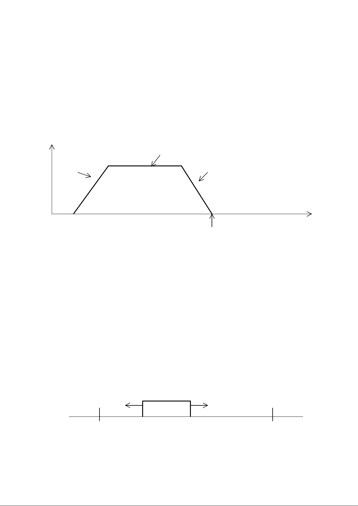
location is known, fast movement can be achieved. A motion profile in Figure 1 represents the velocity of
the motor during a period of time in which the motor moves an object to certain positions.
Motor speed
Target speed
Acceleration Deceleration
Position
Point 1
Point 2
Figure 1. Motion profile
With the ACS 160, two target positions and two motion profiles can be selected. Target speed is selected
with parameter group 12 (Constant Speeds) parameters. Acceleration and deceleration times are selected
with parameter group 22 (Accel/Decel) parameters. Target is selected with group 82 (Positioning)
parameters. The acceleration/deceleration rate must be limited to account for the inertia of the load plus
friction, to allow operation within the torque limits of the motor and ACS160.
When positioning is started, the target speed is used as frequency reference. The motor accelerates with
the selected acceleration time to the target speed. ACS 160 counts the position where deceleration starts,
from the target speed and deceleration time parameter values. Linear ramp is assumed during
deceleration. If S-curve is used, SLOPE GAIN 1 (parameter 8218) needs to be adjusted to compensate
the longer actual deceleration time.
Position is given as motor shaft revolutions. Normally the encoder should be mounted on the motor shaft.
If not so, then the target reference and the encoder pulse number scaling must be changed as explained
later in this engineering guide. Figure 2 shows the load and ACS160 related directions.
Negative direction Positive direction
ACS 160 Direction: REVERSE ACS 160 Direction: FORWARD
Target 1 Target 2
Figure 2. Load and ACS 160 directions
Load
4 3AFE 64693263 REV A EN 27.03.2003
1.1 Basic positioning modes
The ACS 160 has two basic positioning modes, relative and absolute positioning. Relative moves allow to
position the motor in relation to the motor’s previous stopped position. With absolute positioning, moves
are referenced to a predefined zero (Home) position, established by homing operation. Homing means
that a load is driven at a moderate speed to a known position (Home position or “zero position”). The
Positioning mode is selected with parameter 8215 (POS MODE).
1.1.1 Relative positioning
Relative move is used in systems, where items are repetitively moved over a certain distance. The
principle of the operation is shown in Figure 3. When start command is given, the load moves from the
current position to the next position. The distance between the positions is defined with a target
parameter. The position counter starts counting from a defined initial value (usually zero). When the
target distance is counted, ACS 160 output frequency is set to zero. The position counter is reset, when
the next start command is given.
Start/Stop
t
Position counter
t
Figure 3. Relative positioning
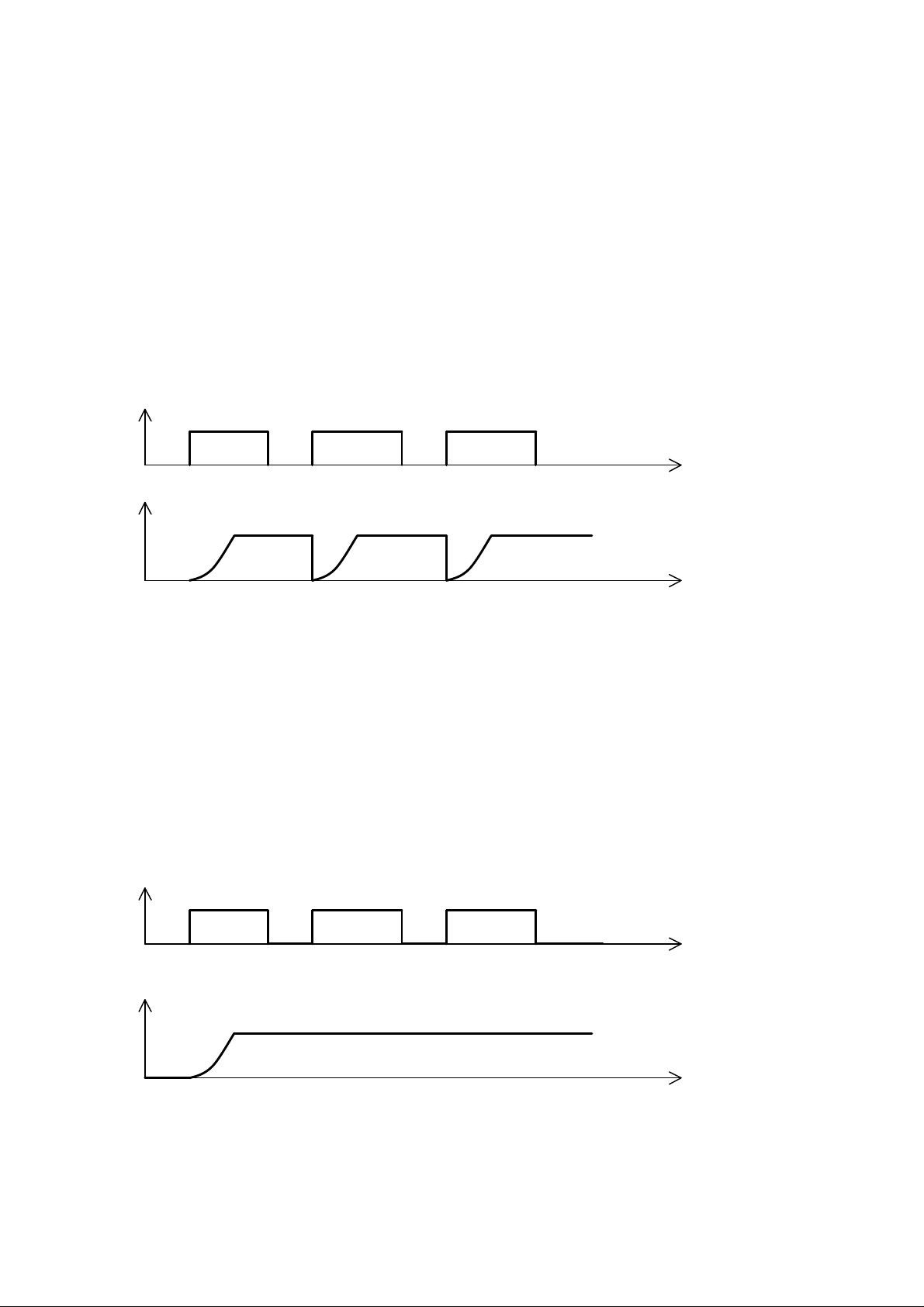
1.1.2 Absolute positioning
Absolute move is used typically in systems, where a load is moved between two positions, which are
defined in relation to zero (Home) position. The principle of the operation is shown in Figure 4. The
position counter is not reset with start/stop-commands. Resetting is done only if a new target is selected.
As start command is given, the load moves to the selected position. The position counter starts counting
from the value of the current position. When the selected target position is reached, ACS 160 output
frequency is set to zero. The new move is possible only when the other target is selected.
Start/Stop
t
Position counter
Figure 4. Absolute positioning
t
5 3AFE 64693263 REV A EN 27.03.2003

2 HOMING
Homing means that a load is driven at a slow speed to a known position (Home position). There are two
homing possibilities available, Jogging and Automatic homing. A manually made homing is called
Jogging. Automatic homing mode is selected with parameter 8216 (HOMING MODE).
Homing Operation
Starting point Target 1 Target 2
(Home position)
Figure 5a. Homing operation
Homing happens only once, and that is when the drive’s power is switched on. The load is driven to Home
position, which can be Target 1, Target 2 or a third position. The use of just one target position selection is
also possible. When the load reaches Home position, the position counter is reset to zero, and the drive is
ready for operation (positioning). The homing operation is illustrated in Figure 5a.
The direction for the homing is set with parameter 1003 DIRECTION. In general this parameter should be
set to 3 (REQUEST). If jogging is used, the load is driven to only one direction, but with a joystick or
fieldbus it is possible to change the direction.
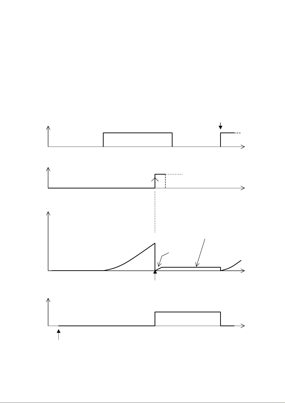
An example of homing with parameter 8216 = 5 (HOMING 2) is given in Figure 5b.
The load is moved between two targets. Proximity switch is used for homing and it is connected to digital
input DI3. The homing switch is placed in Target 1 position. When ACS 160 is powered up, and start
command is given, the homing direction is always the same.
Parameter settings:
P8215 (POS MODE) = 5 (ABS MOVE 1)
P8216 (HOMING MODE) = 5 (HOMING 2)
The homing direction is always reverse (DI3 input is inactive). When Home position is reached, the
proximity switch is activated (DI3 activates) and the ACS 160 output frequency changes to 0 Hz.
6 3AFE 64693263 REV A EN 27.03.2003
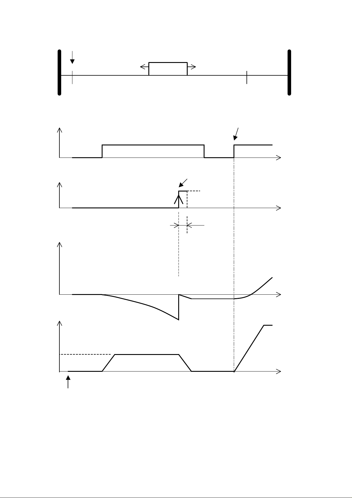
Example of homing
Mechanical Mechanical
limit limit
Proximity switch (DI3)
Load
Target 1 Target 2
Home position
DI1 Start/Stop Positioning mode starts
t
DI3 Proximity switch Home position reached
Position counter
ACS 160 output frequency
P1207 CONST SPEED 6
0
t
min. 10 ms
t
t
Power on
Figure 5b. Example of homing operation when homing mode = 5 (HOMING 2)
7 3AFE 64693263 REV A EN 27.03.2003
2.1 Manual homing (jogging)
Jogging is possible when the external control place EXT1 has been selected. Control place selection is
made with parameter 1102 (EXT1/EXT2 SEL). As default EXT1/EXT2 selection is made with digital input
DI2. Jogging speed is set with analogue input AI1. Jogging direction is defined with the direction lock
parameter 1003 (DIRECTION).
Special cases
If the frequency reference and commands are given with a keypad, through a serial communication, or
with a joystick to AI1 or AI2, the motor rotation can be set to both directions. In this case parameter 1003
must be set to 3 (=REQUEST).
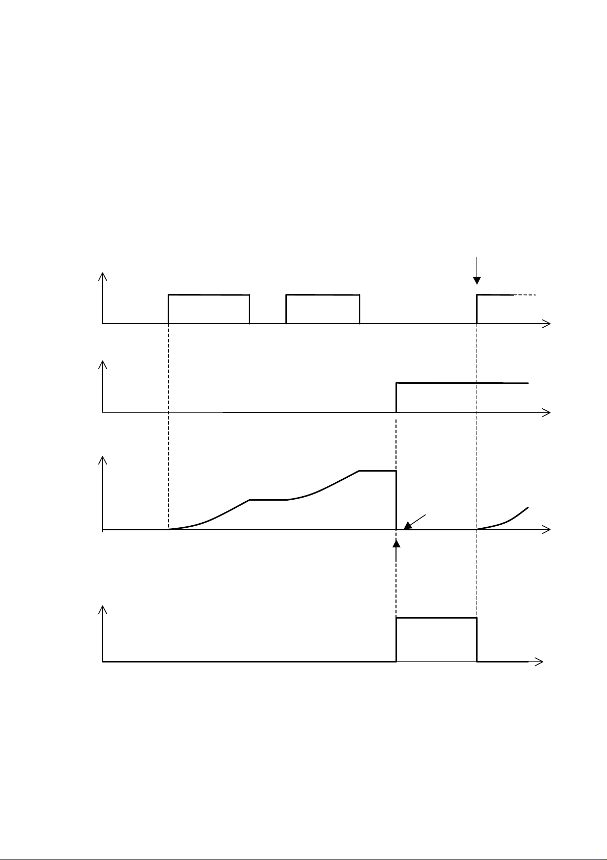
When a load has moved to Home position, stop command must be given. After that the control place is
changed from EXT1 to EXT2 with DI2. This change from EXT1 to EXT2 sets the P8225 and P8226
(HOME POS LO, HI) values to the position counter. The relay (AT TARGET) is activated. The operation
is illustrated in Figure 5c.
Positioning starts
DI1 Start/Stop
start
stop
t
DI2 (EXT2/EXT1)
Position counter
Relay 2 output
(AT TARGET)
EXT2
EXT1
t
P8225,P8226
t
Homing
Relay activated
Relay not activated
Figure 5c. Manual homing / jogging
t
8 3AFE 64693263 REV A EN 27.03.2003
2.2 Automatic homing
This homing (with a limit switch) is possible only when the external control place EXT2 has been selected.
In this mode a load is moved at moderate speed into a limit switch. The limit switch must be connected to
digital input DI3. Homing can be made only once after the supply voltage has been switched on to
ACS 160.
Homing starts when start command is given. The homing speed is defined with constant speed parameter
1207 (CONST SPEED 6). The homing direction is defined with parameter 8216 (HOMING MODE) and
the input value of digital input DI3. Home position is reached when the limit switch is activated and DI3
input changes state.
In Home position, the ACS 160 frequency reference is internally set to zero and the relay (AT TARGET) is
activated. Output frequency goes to zero with the selected ramp time. Homing is finished when stop
command is given. The next start command activates the positioning mode. An example of operation is
given in Figure 6.
Start Positioning starts
DI1 Start/Stop
Stop
t
DI3 Limit switch
Position counter
Relay 2 output
(AT TARGET)
t
During deceleration from homing speed
to zero position counter value has increased
P8225, P8226
t
Homing
Power On
Figure 6. Automatic homing
t
9 3AFE 64693263 REV A EN 27.03.2003

3 START UP PROCEDURES
An ACS 160 drive with an incremental encoder connection can be used for simple positioning
applications. The encoder connection is enabled by choosing Application macro 14, Positioning. The
analogue output
does not function after this selection. It is assumed by positioning logic that the encoder is installed to the
motor shaft.
3.1 Encoder installation
Connect encoder to ACS 160
§ Connect encoder output pulses (phase shift between pulse channels: 90 electrical degrees) to digital
inputs DI4 and DI5.
§ Connect 24 V supply voltage to encoder. Supply voltage can be taken from ACS 160 or from an
external power supply.
Activate encoder pulse counting
§ Set parameter 9902 value to 14 (POSITIONING), turn ACS 160 power off and then on again.
(Necessary for activating the pulse counting.) Set all other group 99 (APPLIC MACRO) parameters.
Check that the encoder pulses are connected to digital inputs DI4 and DI5
§ Rotate the motor shaft slowly and observe that DI4 and DI5 status is changing between 1 and 0 in
parameters 0117 (DI1-DI4 STATUS) and 0121 (DI5 & RELAYS)
Check that encoder direction matches to ACS 160 direction
§ Rotate the motor and encoder at slow speed and observe that the position counter is counting up (to
more positive direction) when ACS 160 direction is forward, and down when ACS 160 direction is
reverse. If the directions do not match, switch over the DI4/DI5 connections. The pulse counter value
can be read from parameters 8227 and 8228 (POS ACT LO, HI). ACS 160 direction can be read from
the control panel display. If the pulse counter is not counting up or down, check that the encoder
pulses have a 90-degree phase shift.
Set positioning related parameters
§ Positioning mode parameters are in parameter group 82.
§ Positioning and homing frequency references are set with group 12, the Constant Speeds parameters.
It is recommended to use low frequency references at the beginning of commissioning, and set them
to optimal values later, when proper operation of positioning has been ensured.
Use a brake chopper if short deceleration times and/or high inertia load is used
§ Usage without a brake chopper overvoltage controller can effect to actual deceleration times and
cause momentary overshoot when reaching the target. Brake chopper operation is enabled with
parameter 2005 (OVERVOLT CTRL).
3.2 Encoder connection
3.2.1 Encoder
A two-channel single ended incremental encoder must be used. Encoder outputs are connected to digital
inputs DI4 and DI5. Phase shift between encoder channel A and channel B signals must be 90 degrees.
Encoder pulses/rev: 1 – 8192 (1024 recommended).
Max. pulse frequency: 200 kHz.
Encoder supply voltage: 24Vdc
Encoder cable length: 3 m max. is recommended. See the encoder’s datasheet.
Minimum input voltage to digital inputs DI4 and DI5: 12 V.
The pulse counter is programmed to up/down –counter, calculating both rising and falling edges of
channel A and B encoder pulses. The pulse count is read from this 16 bit counter at 4 ms time level.
10 3AFE 64693263 REV A EN 27.03.2003

Example
1 1 0 1
X 1 0 1
If the encoder pulse count is 1024 pulses/rev => the pulse counter counts 4*1024 =4096 pulses/rev.
See Figure 7.
90º
DI4:
(CHA or B)
Counting down:
DI5:
(CHB or A)
DI4:
Counting up: DI5:
Figure 7. Encoder pulses
3.2.2 Choosing encoder connection mode
(Application macro Positioning)
- Set parameter 9902 (APPLIC MACRO) value to 14 (POSITIONING)
- Turn the ACS 160 supply voltage off and then on again. (Necessary for activating the pulse counting.)
- Set the other group 99 parameters.
Checking encoder connection to ACS 160 I/O –terminal
The wiring between encoder and ACS 160 can be checked from parameters 0117 (DI1-DI4 STATUS) and
0121 (DI5 & RELAYS):
Rotate encoder shaft slowly and check that DI4 and DI5 status change between 0 and 1.
DI4 status: fourth digit from right in parameter 0117.
DI5 status: third digit from right in parameter 0121.
Parameter 0117: Parameter 0121:
Panel display: Panel display:
DI4 DI5
Matching the encoder direction of rotation and the ACS 160 direction
The pulse counter must count up (to more positive direction), when the ACS 160 direction of rotation is
forward, and down, when the ACS 160 direction is reverse. If the directions do not match, the encoder
output channels must be changed. The pulse counter value can be read from parameters 8227 and 8228
(POS ACT LO, HI).
The safest way to check this is in the Jogging mode. External control place EXT1 is used. If the
application macro 14 default settings are used, the digital input DI2 must be inactive and the frequency
reference is given with analogue input AI1. The direction is given with parameter 1003 (DIRECTION).
External control place EXT1 can also be selected when setting the parameter 1102 (EXT1/EXT2 SEL)
value to 6 (EXT1). The frequency reference can also be given with the control panel, setting the
parameter 1103 value to 0 (KEYPAD). Start/stop and direction commands can be given with the panel,
setting the parameter 1001 (EXT1 COMMANDS) value to 8 (KEYPAD). Local control mode can be used
with panel also to give start/stop and direction commands.
11 3AFE 64693263 REV A EN 27.03.2003
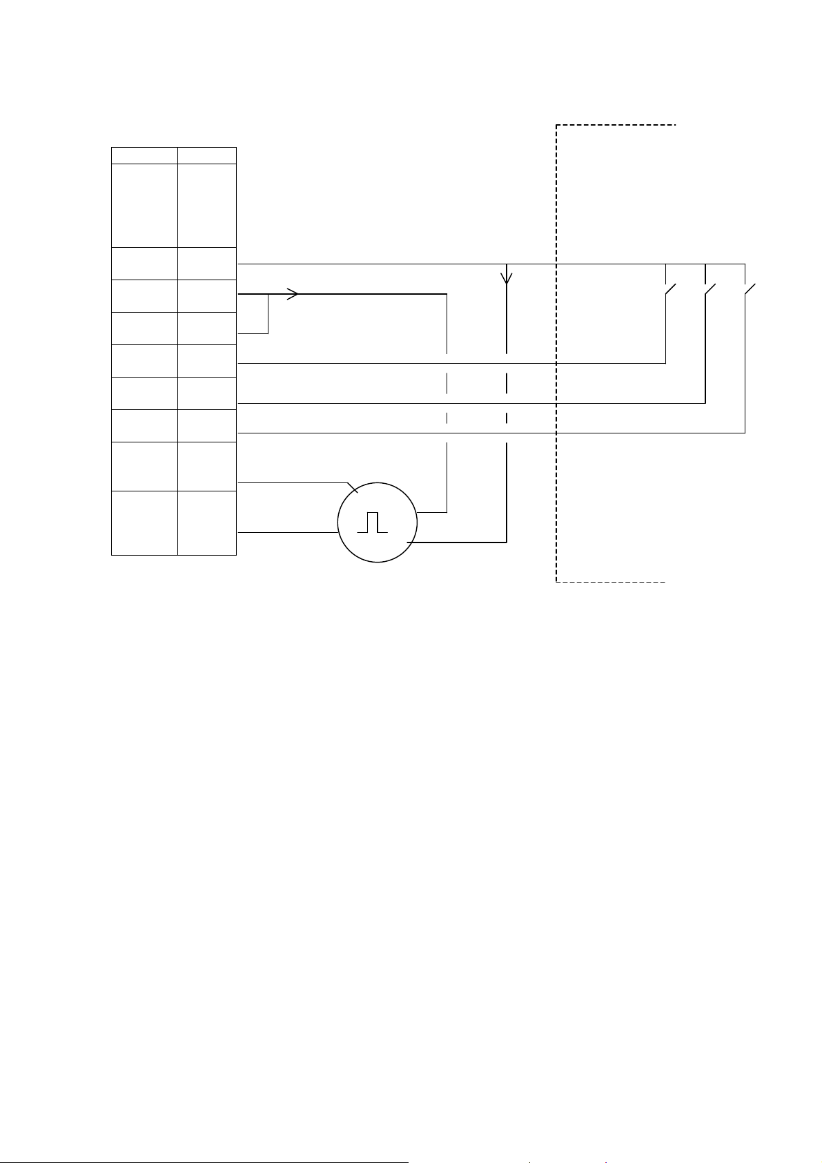
Encoder connection example 1
ACS 160 PLC
SCR 1
AGND 8 GND
24V 9 +24 V S1 S2 S3
DCOM 10
DI1 11 Start/Stop
DI2 12 Target1/2 selection
DI3 13 Homing
DI4 14
CH A (npn )
DI5 15
CH B (npn ) +24V
GND
ENCODER
Figure 8. Encoder connection example 1
In Figure 8, the ACS 160 digital inputs are configured as NPN-connected. The encoder supply voltage is
taken from the ACS 160 24 V auxiliary voltage output. A shielded cable is recommended.
12 3AFE 64693263 REV A EN 27.03.2003
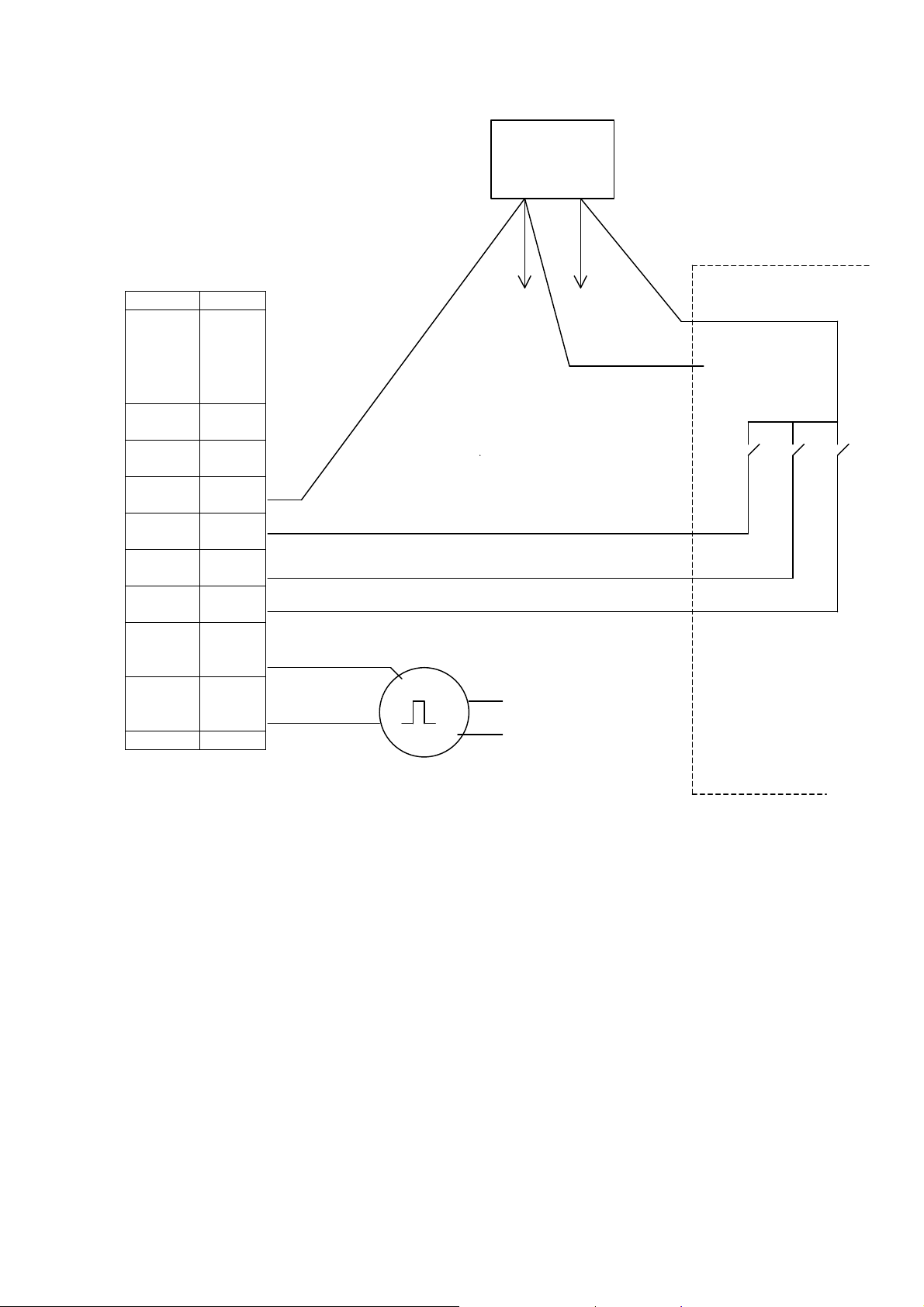
Encoder connection example 2
External 24 V power supply
0 V +24 V
ACS 160 PLC
SCR 1 0 V + 24 V +24 V
(to encoder) (to encoder)
GND
AGND 8
24V 9 S1 S2 S3
DCOM 10
DI1 11 Start/Stop
DI2 12 Target 1/2 selection
DI3 13 Homing
DI4 14
CH A (pnp)
DI5 15 +24 V
CH B (pnp)
0 V
ENCODER
Figure 9. Encoder connection example 2
In Figure 9, the ACS 160 digital inputs are configured as PNP-connected. An external power supply is
used for the digital inputs and encoder.
13 3AFE 64693263 REV A EN 27.03.2003

4 POSITIONING MODES
With the parameter 8215 (POS MODE), it is possible to select the positioning mode. The Positioning
mode defines the way in which the positioning is done. Depending on the application the selection
between relative and absolute positioning is done with this parameter.
Six different positioning modes can be selected: Relative move with position correction, Absolute move,
Absolute move with cyclic correction, Absolute move with cyclic correction 2, Relative move without
position correction and Continuous move 1.
A detailed description of each of the different positioning modes is given on the following pages.
The table below presents the positioning modes used for certain type of application characteristics.
Mode Application characteristic
Relative move with
position correction
Absolute move
Absolute move with
cyclic correction 1
Absolute move with
cyclic correction 2
Relative move without
position correction
Continuous move
Repetitive move in one direction. Conveyor moves to one direction, with
position correction properties.
Load needs to be moved between two positions.
Load needs to be moved between two positions, but taking drift error in
account.
Load is moved between two positions, but considering drift error. (Other
configuration as Absolute move cc1)
Repetitive move in one direction. Conveyor moves in one direction, without
position correction properties.
Continuous movement between two positions, with possibility for delay time
at turning points.
4.1 Relative move with position correction
(4 = RELAT MOVE 1)
Selected target position is relative to previous target position. When start command is given, the
position counter is first reset to zero and then corrected with the distance between the actual and
desired stopping position. The purpose of this is to prevent the axis to “creep” from its original
zero position. Correction is made only in cases, when the previous move has reached the target
window area.
Without this corrective action, in applications where the same incremental move should be done
time after time, the position counter would be zeroed at the actual (stopping) positions, not at the
desired (stopping) positions. Because of this, the actual stopping position becomes the new zero
position. Without a corrective action the zero position would “creep” either forward or reverse the
direction from the desired position. See Figure 10.
If there is a need to do a positioning application, where a load must be moved to the opposite
direction, a negative value can be set as the target position. By doing so the rotation of the shaft
will be reversed when this particular target is selected.
14 3AFE 64693263 REV A EN 27.03.2003
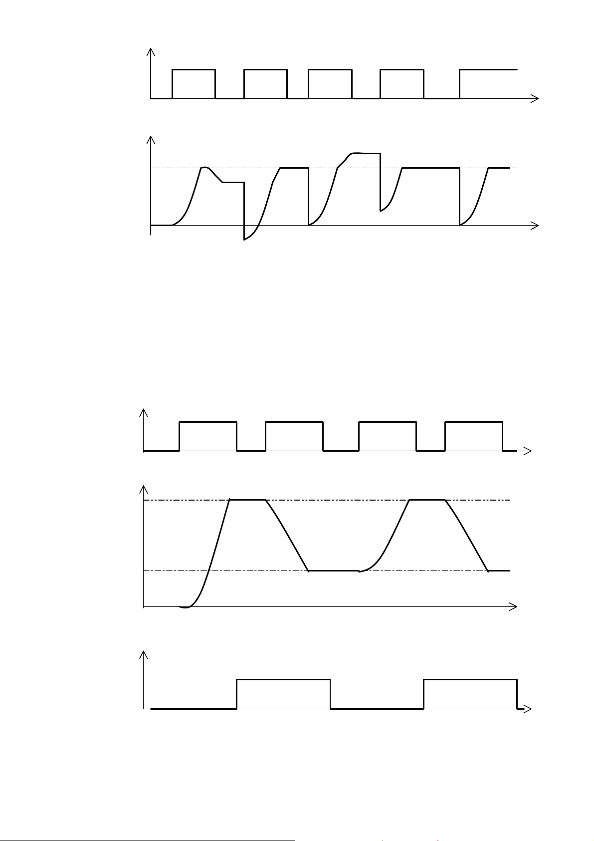
DI1 Start/Stop
Position counter
Target
0 t
Figure 10. Relative move 1 mode with corrective action.
4.2 Absolute move
(5 = ABS MOVE 1)
t
The selected target position is absolute. The position counter is not reset, when start command is
given. This mode is used especially, when the load is moved between two positions as shown in
Figure 11.
DI1 Start/Stop
Position counter
t
Target 1
Target 2
t
Target selection
Target 2
Target 1
Figure 11. Absolute move 1 mode with two targets
15 3AFE 64693263 REV A EN 27.03.2003
t
 Loading...