


ABB A40, A50, A63, A75, A95 Technical Data
...
|
|
line |
|
|
|
the |
|
|
Contactors |
||
1 |
|||
Across |
|
||
IEC Technical data
A/E/L40, A/E/F50...A/F110, 3-pole Utilization characteristics
Main pole - Utilization characteristics according to IEC
Contactor types |
|
AC operated |
A40 |
|
A50 |
A63 |
A75 |
A95 |
A110 |
|||||||
|
|
|
|
|
DC operated |
AL40 |
|
AE50 |
AE63 |
AE75 |
– |
– |
||||
|
|
|
|
|
|
TAL40 |
|
TAE50 |
– |
|
TAE75 |
– |
– |
|||
|
|
|
|
|
AC / DC operated |
– |
|
|
AF50 |
AF63 |
AF75 |
AF95 |
AF110 |
|||
Standards |
|
|
IEC 60947-1 / 60947-4-1 and EN 60947-1 / 60947-4-1 |
|
|
|
||||||||||
Rated operational voltage Ue max. |
|
690 V |
|
1000 V (690 V for AF.. contactors) |
|
|
1000 V |
|
||||||||
|
|
|
|
|
||||||||||||
Rated frequency (without derating) |
|
50/60 Hz |
|
|
|
|
|
|
|
|
|
|||||
Conventional free-air thermal current Ith |
|
|
|
|
|
|
|
|
|
|
|
|
||||
acc. to IEC 60947-4-1, open contactors, θ ≤ 40 °C |
|
65 |
A |
|
100 A |
125 A |
125 A |
145 A |
160 A |
|||||||
With conductor cross-sectional area |
|
16 mm² |
|
35 mm² |
50 mm² |
50 mm² |
50 mm² |
70 mm² |
||||||||
AC-1 Utilization category |
|
|
|
|
|
|
|
|
|
|
|
|
||||
For air temperature close to contactor |
|
|
|
|
|
|
|
|
|
|
|
|
||||
Ie / Rated operational current AC-1 |
θ ≤ 40 °C |
60 |
A |
|
100 A |
115 A |
125 A |
145 A |
160 A |
|||||||
Ue max. ≤ 690 V, 50/60 Hz |
θ ≤ 55 °C |
60 |
A |
|
85 |
A |
95 |
A |
105 A |
135 A |
145 A |
|||||
|
|
|
|
|
θ ≤ 70 °C (3) |
42 |
A |
|
70 |
A |
80 |
A |
85 |
A |
115 A |
130 A |
With conductor cross-sectional area |
|
16 mm² |
|
35 mm² |
50 mm² |
50 mm² |
50 mm² |
70 mm² |
||||||||
AC-3 Utilization category |
|
|
|
|
|
|
|
|
|
|
|
|
||||
For air temperature close to contactor θ ≤ 55 °C |
|
|
|
|
|
|
|
|
|
|
|
|||||
Ie / Max. rated operational current AC-3 (1) |
|
|
|
|
|
|
|
|
|
|
|
|
||||
|
|
|
|
|
220-230-240 V |
40 |
A |
53 |
A |
65 |
A |
75 |
A |
96 A |
110 A |
|
|
|
|
|
|
380-400 V |
37 |
A |
50 |
A |
65 |
A |
75 |
A |
96 A |
110 A |
|
|
|
|
|
|
415 V |
37 |
A |
50 |
A |
65 |
A |
75 |
A |
96 A |
110 A |
|
|
|
|
|
|
||||||||||||
|
M |
|
||||||||||||||
|
3-phase motors |
440 V |
37 |
A |
45 |
A |
65 |
A |
70 |
A |
93 A |
100 A |
||||
3 |
|
|
||||||||||||||
|
|
|
500 V |
33 |
A |
45 |
A |
55 A |
65 |
A |
80 A |
100 A |
||||
|
|
|
|
|
690 V |
25 |
A (4) |
35 |
A |
43 |
A |
46 |
A |
65 A |
82 A |
|
|
|
|
|
|
1000 V |
– |
|
23 |
A (6) |
25 |
A (6) |
28 |
A (6) |
30 A |
30 A |
|
Rated operational power AC-3 (1)
|
|
|
|
|
220-230-240 V |
11 kW |
15 kW |
18.5 kW |
22 kW |
25 kW |
30 kW |
|
|
|
|
|
|
380-400 V |
18.5 kW |
22 kW |
30 kW |
37 kW |
45 kW |
55 kW |
|
|
|
|
|
1500 r.p.m. 50 Hz |
415 V |
18.5 kW |
25 kW |
37 kW |
40 kW |
55 kW |
59 kW |
|
|
|
|
|
|||||||||
|
M |
|||||||||||
|
1800 r.p.m. 60 Hz |
440 V |
22 kW |
25 kW |
37 kW |
40 kW |
55 kW |
59 kW |
||||
3 |
|
|
||||||||||
|
|
3-phase motors |
500 V |
22 kW |
30 kW |
37 kW |
45 kW |
55 kW |
59 kW |
|||
|
|
|
|
|
690 V |
22 kW (4) |
30 kW |
37 kW |
40 kW |
55 kW |
75 kW |
|
|
|
|
|
|
1000 V |
– |
30 kW (6) |
33 kW (6) |
37 kW (6) |
40 kW |
40 kW |
|
Rated making capacity AC-3 |
|
10 x Ie AC-3 acc. to IEC 60947-4-1 |
|
|
|
|
||||||
Rated breaking capacity AC-3 |
|
8 x Ie AC-3 acc. to IEC 60947-4-1 |
|
|
|
|
||||||
AC-8a Utilization category (without thermal overload relay - Ue 400 V 50/60 Hz - θ ≤ 40 °C) |
|
|
|
|
|
|
||||||
Ie / Rated operational current AC-8a |
|
50 A |
63 A |
|
85 A |
95 A |
120 A |
140 A |
||||
Rated operational power AC-8a |
|
22 kW |
30 kW |
|
45 kW |
45 kW |
55 kW |
75 kW |
||||
Short-circuit protection device for contactors |
|
|
|
|
|
|
|
|
||||
without thermal overload relay - Motor protection excluded (2) |
|
|
|
|
|
|
|
|||||
|
|
|
|
|
|
|
|
|
|
|
||
Ue ≤ 500 V AC - gG type fuse |
|
63 A |
100 A |
|
125 A |
160 A |
160 A |
200 A |
||||
Rated short-time withstand current Icw |
1 s |
600 A |
1000 A |
|
|
1320 A |
|
|||||
at 40 °C ambient temperature, |
10 s |
400 A |
650 A |
|
|
800 A |
|
|||||
in free air from a cold state |
30 s |
225 A |
370 A |
|
|
500 A |
|
|||||
|
|
|
|
|
|
|
|
|||||
|
|
|
|
|
1 min |
150 A |
250 A |
|
|
350 A |
|
|
|
|
|
|
|
15 min |
65 A |
110 A |
|
135 A |
135 A |
160 A |
175 A |
Maximum breaking capacity |
|
|
|
|
|
|
|
|
||||
cos φ = 0.45 |
|
at 440 V |
820 A (5) |
1300 A |
|
|
1160 A |
|
||||
(cos φ = 0.35 for Ie > 100 A) |
at 690 V |
340 A (5) |
630 A |
|
|
800 A |
|
|||||
Power dissipation per pole |
Ie / AC-1 |
3 W |
5 W |
|
6.5 W |
7 W |
6.5 W |
7.5 W |
||||
|
|
|
|
|
Ie / AC-3 |
1.3 W |
1.3 W |
|
1.5 W |
2 W |
2.7 W |
3.6 W |
Max. electrical switching frequency |
AC-1 |
600 cycles/h |
600 cycles/h (300 for AF.., AE.., TAE..) |
300 cycles/h |
|
|||||||
|
|
|
|
|
AC-3 |
1200 cycles/h |
600 cycles/h (300 for AF.., AE.., TAE..) |
300 cycles/h |
|
|||
|
|
|
|
|
AC-2, AC-4 |
300 cycles/h |
150 cycles/h |
|
|
|
|
|
|
|
|
|
|
|
|
|
|
|
|
|
|
(1)For the corresponding kW/A or hp/A values of 1500 r.p.m, 50 Hz or 1800 r.p.m, 60 Hz, 3-phase motors, see "Motor rated operational powers and currents".
(2)For the protection of motor starters against short circuits, see "Coordination with short-circuit protection devices".
(3)Unauthorized for TAL.., TAE.. contactors.
(4)AC-3, 690 V values for AL40 and TAL40 contactors: 18.5 kW, Ie = 21 A.
(5)Max. breaking capacity for AL40 and TAL40 contactors: 470 A at 440 V, 175 A at 690 V.
(6)AF contactors excluded.
1.84 |
Low Voltage Products & Systems |
1SXU000023C0202 Rev. A |
ABB Inc. • 888-385-1221 • www.abb.us/lowvoltage |

|
|
line |
|
|
|
the |
|
|
Contactors |
||
1 |
|||
Across |
|
||
UL/NEMA/CSA Technical data
A/E/L40; A/E/F50...A/F110, A/E/F50N2...A/E/F75N3, 3-pole Utilization characteristics
Main pole - Utilization characteristics according to UL / NEMA / CSA
Contactor types |
AC operated |
A40 |
A50 |
A63 |
|
A75 |
A95 |
A110 |
|
DC operated |
AL40, TAL40 |
AE50, TAE50 |
AE63 |
|
AE75, TAE75 |
– |
– |
|
AC / DC operated |
– |
AF50 |
AF63 |
|
AF75 |
AF95 |
AF110 |
Standards |
|
UL 508, CSA C |
22.2 N°14 |
|
|
|
|
|
Max. operational voltage |
|
600 V |
|
|
|
|
|
|
NEMA size |
|
– |
2 |
– |
|
3 |
– |
– |
NEMA continuous amp rating |
Thermal current |
– |
45 A |
– |
|
90 A |
– |
– |
NEMA maximum horse power ratings 1-phase, 60 Hz |
|
|
|
|
|
|
|
|
|
115 V AC |
– |
3 hp |
– |
|
– |
– |
– |
|
230 V AC |
– |
7-1/2 |
– |
|
– |
– |
– |
NEMA maximum horse power ratings 3-phase, 60 Hz |
|
|
|
|
|
|
|
|
|
200 V AC |
– |
10 hp |
– |
|
25 hp |
– |
– |
|
230 V AC |
– |
15 hp |
– |
|
30 hp |
– |
– |
|
460 V AC |
– |
25 hp |
– |
|
50 hp |
– |
– |
|
575 V AC |
– |
25 hp |
– |
|
50 hp |
– |
– |
UL / CSA general use rating |
|
|
|
|
|
|
|
|
600 V AC |
|
60 A |
80 A |
90 A |
|
105 A |
125 A |
150 A |
With conductor cross-sectional area |
|
AWG 6 |
AWG 4 |
AWG 3 |
|
AWG 2 |
AWG 1 |
AWG 1/0 |
UL / CSA maximum 1-phase motor rating |
|
|
|
|
|
|
|
|
Full load current |
120 V AC |
34 A |
34 A |
56 A |
|
80 A |
80 A |
100 A |
|
240 V AC |
40 A |
40 A |
50 A |
|
68 A |
88 A |
110 A |
Horse power rating |
120 V AC |
3 hp |
3 hp |
5 hp |
|
7.5 hp |
7.5 hp |
10 hp |
|
240 V AC |
7.5 hp |
7.5 hp |
10 hp |
|
15 hp |
20 hp |
25 hp |
UL / CSA maximum 3-phase motor rating |
|
|
|
|
|
|
|
|
Full load current (1) |
200-208 V AC |
32.2 A |
48.3 A |
62.1 A |
|
78.2 A |
92 A |
92 A |
|
220-240 V AC |
42 A |
54 A |
68 A |
|
80 A |
80 A |
104 A |
|
440-480 V AC |
40 A |
52 A |
77 A |
|
77 A |
77 A |
96 A |
|
550-600 V AC |
41 A |
52 A |
77 A |
|
77 A |
77 A |
99 A |
Horse power rating (1) |
200-208 V AC |
10 hp |
15 hp |
20 hp |
|
25 hp |
30 hp |
30 hp |
|
220-240 V AC |
15 hp |
20 hp |
25 hp |
|
30 hp |
30 hp |
40 hp |
|
440-480 V AC |
30 hp |
40 hp |
60 hp |
|
60 hp |
60 hp |
75 hp |
|
550-600 V AC |
40 hp |
50 hp |
75 hp |
|
75 hp |
75 hp |
100 hp |
Max. electrical switching frequency |
|
|
|
|
|
|
|
|
For general use |
|
600 cycles/h |
600 cycles/h (300 for AF.., AE..) |
|
300 cycles/h |
|
||
For motor use |
|
1200 cycles/h |
600 cycles/h (300 for AF.., AE..) |
|
300 cycles/h |
|
||
(1) For the corresponding kW/A or hp/A values of 1500 r.p.m, 50 Hz or 1800 r.p.m, 60 Hz, 3-phase motors, see “Motor rated operational powers and currents”.
General technical data
Contactor types |
|
AC operated |
A40 |
A50 |
A63 |
A75 |
A95 |
A110 |
|
|
|
|
DC operated |
AL40, TAL40 |
AE50, TAE50 |
AE63 |
AE75, TAE75 |
– |
– |
|
|
|
AC / DC operated |
– |
AF50 |
AF63 |
AF75 |
AF95 |
AF110 |
Rated insulation voltage Ui |
|
|
|
|
|
|
|
||
|
acc. to IEC 60947-4-1 |
|
1000 V |
|
|
|
|
|
|
|
acc. to UL |
|
|
600 V |
|
|
|
|
|
Rated impulse withstand voltage Uimp. |
|
8 kV |
|
|
|
|
|
||
Electromagnetic compatibility |
|
AF contactors complying with IEC 60947-1 / EN 60947-1 - Environment A |
|
||||||
Ambient air temperature close to contactor |
|
|
|
|
|
|
|
||
|
Operation |
Fitted with thermal overload relay |
-25...+55 °C |
|
|
|
|
|
|
|
|
Without thermal overload relay |
|
-40…+70 °C (55 °C max. for TAL.., and TAE.. contactor) |
|
|
|||
|
Storage |
|
|
-60...+80 °C |
|
|
|
-40...+70 °C |
|
Climatic withstand |
|
|
acc. to IEC 60068-2-30 and 60068-2-11 |
|
acc. to IEC 60068-2-30 |
||||
|
|
|
|
UTE C 63-100 specification II |
|
|
|
|
|
Maximum operating altitude (without derating) |
|
3000 m |
|
|
|
|
|
||
Mechanical durability |
|
|
|
|
|
|
|
|
|
|
Number of operating cycles |
|
10 millions operating cycles (5 millions for AE.. and TAE..) |
|
|
||||
|
Max. switching frequency |
|
3600 cycles/h (300 for AF contactors) |
|
|
|
|||
Shock withstand acc. to IEC 60068-2-27 and EN 60068-2-27 |
|
|
|
|
|
|
|
||
Mounting position 1 |
|
|
|
|
|
|
|
|
|
|
|
C1 |
Shock direction |
1/2 sinusoidal shock for 11 ms: no change in contact position, closed or open position (2) |
|||||
|
|
|
A |
20 g |
|
|
For AL40, TAL40 |
|
|
A |
A B1 |
B2 |
B1 |
10 g closed position / 5 g open position |
A : 20 g closed position / 10 g open position |
||||
|
|
|
B2 |
15 g |
|
|
B1 : 15 g closed position / 5 g open position |
||
|
|
|
|
|
B2 : 10 g closed position / 10 g open position |
||||
|
|
|
C1 |
20 g |
|
|
|||
|
|
|
|
|
C1 : 20 g closed position / 8 g open position |
||||
|
|
C2 |
C2 |
20 g |
|
|
C2 : 14 g closed position / 8 g open position |
||
(2) These values are not valid for rail mounting with contactors A95 ... A110 and AF95 ... AF110.
1.88 |
Low Voltage Products & Systems |
1SXU000023C0202 Rev. A |
ABB Inc. • 888-385-1221 • www.abb.us/lowvoltage |
|
|
line |
|
|
|
the |
|
|
Contactors |
||
1 |
|||
Across |
|
||
General technical data
AF50...AF110, 3-pole
Coil & mounting characteristics
Magnet system characteristics
Contactor types |
|
AC / DC operated |
AF50 |
AF63 |
AF75 |
AF95 |
AF110 |
Coil operating limits |
|
AC or DC supply |
At θ ≤ 70 °C 0.85 x Uc min...1.1 x Uc max. |
|
|
||
acc. to IEC 60947-4-1 |
|
|
Please also refer to "Mounting characteristics and conditions for use" |
|
|||
AC control voltage |
Rated control circuit voltage Uc |
48…250 V 50/60 Hz |
|
|
|
||
50/60 Hz |
Coil consumption |
Average pull-in value |
210 VA |
|
|
350 VA |
|
|
|
|
|||||
|
|
Average holding value |
7 VA / 2.8 W |
|
|
7 VA / 3.5 W |
|
DC control voltage |
Rated control circuit voltage Uc |
20…250 V DC |
|
|
|
|
|
|
Coil consumption |
Average pull-in value |
190 W |
|
|
400 W |
|
|
|
Average holding value |
2.8 W |
|
|
2 W |
|
Drop-out voltage |
|
|
55 % of Uc min. |
|
|
|
|
Voltage sag immunity |
|
|
Conditions of use on request |
|
|
|
|
acc. to SEMI F47 |
|
|
|
|
|
|
|
Dips withstand |
|
|
≥ 20 ms |
|
|
|
|
Operating time |
|
|
|
|
|
|
|
Between coil energization and: |
N.O. contact closing |
30…100 ms |
|
|
30…80 ms |
|
|
|
|
N.C. contact opening |
27…95 ms |
|
|
27…77 ms |
|
Between coil de-energization and: |
N.O. contact opening |
30…110 ms |
|
|
55…125 ms |
|
|
|
|
N.C. contact closing |
35…115 ms |
|
|
60…130 ms |
|
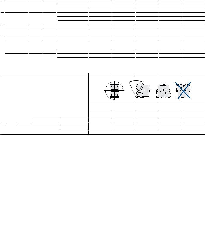
Mounting characteristics and conditions for use
Contactor types |
|
AC / DC operated |
AF50 |
AF63 |
AF75 |
AF95 |
AF110 |
|
Mounting positions |
|
|
|
Pos. 2 |
+30° -30° |
|
|
|
|
|
|
|
Pos. 4 |
|
|
|
|
|
|
|
|
|
Pos. 3 |
|
|
|
|
|
|
|
|
Pos. 1 |
Pos. 1 ± 30° |
Pos. 5 |
Pos. 6 |
|
|
|
|
Max. built-in and add-on N.O. or N.C. auxiliary contacts: |
|
|
||
|
|
|
|
see accessory fitting details for 3-pole contactor AF50 ... AF110 |
|
|||
Control voltage / Ambient temperature |
|
|
|
|
|
|
||
Mounting |
|
1, 1±30°, 2, 3, 4, 5 |
at θ ≤ 70 °C |
0.85 x Uc min…1.1 x Uc max. |
|
|
|
|
positions |
|
6 |
|
Unauthorized |
|
|
|
|
Mounting distances |
|
|
The contactors can be assembled side by side |
|
|
|||
Fixing |
On rail according to IEC 60715, EN 60715 |
35 x 15 mm or 75 x 25 mm |
|
– |
|
|||
|
By screws (not supplied) |
|
2 x M6 screws placed diagonally |
|
|
|
||
1.94 |
Low Voltage Products & Systems |
1SXU000023C0202 Rev. A |
ABB Inc. • 888-385-1221 • www.abb.us/lowvoltage |
 Loading...