


KN2600(ENGLISH)-SX KN2400-SX
Matsushita Electric Industrial Co., Ltd.
Web Site: http://www.panasonic.co.jp/global/
ENGLISH
 KN2600-SX KN2400-SX KEYBOARD
KEYBOARD
SX-KN2400 SX-KN2600
Operating Instructions
Before connecting, operating or adjusting this product, please read these instructions completely. Please keep this manual for future reference.
QQTG0692 |
|
|
Se0203S0 |
ENGLISH |
QQTG0692 |
01_Caution for AC Mains Lead.fm 2
Caution for AC Mains Lead
(For United Kingdom)
(For the type as shown in figures A and B)
For your safety, please read the following text carefully.
This appliance is supplied with a moulded three pin mains plug for your safety and convenience. A 5-ampere fuse is fitted in this plug. Should the fuse need to be replaced please ensure that the replacement fuse has a rating of 5-ampere and that it is approved by ASTA or BSI to BS1362.
Check for the ASTA mark  or the BSI mark
  on the body of the fuse.
If the plug contains a removable fuse cover you must ensure that it is refitted when the fuse is replaced. If you lose the fuse cover the plug must not be used until a replacement cover is obtained. A replacement fuse cover can be purchased from your local dealer.
CAUTION!
IF THE FITTED MOULDED PLUG IS UNSUITABLE FOR THE SOCKET OUTLET IN YOUR HOME THEN THE FUSE SHOULD BE REMOVED AND THE PLUG CUT OFF AND DISPOSED OF SAFELY. THERE IS A DANGER OF SEVERE ELECTRICAL SHOCK IF THE CUT OFF PLUG IS INSERTED INTO ANY 13-AMPERE SOCKET.
If a new plug is to be fitted please observe the wiring code as stated below. If in any doubt please consult a qualified electrician.
IMPORTANT
The wires in this mains lead are coloured in accordance with the following code:
Blue: Neutral, Brown: Live.
As these colours may not correspond with the coloured markings identifying the terminals in your plug, proceed as follows:
The wire which is coloured Blue must be connected to the terminal which is marked with the letter N or coloured Black or Blue.
The wire which is coloured Brown must be connected to the terminal which is marked with the letter L or coloured Brown or Red.
2
WARNING: DO NOT CONNECT EITHER WIRE TO THE EARTH TERMINAL WHICH IS MARKED WITH THE LETTER E, BY THE EARTH
SYMBOL  OR COLOURED GREEN OR GREEN/ YELLOW.
THIS PLUG IS NOT WATERPROOF —KEEP DRY.
Before use
Remove the connector cover.
How to replace the fuse
The location of the fuse differ according to the type of AC mains plug (figures A and B). Confirm the AC mains plug fitted and follow the instructions below. Illustrations may differ from actual AC mains plug.
1. Open the fuse cover with a screwdriver.
Figure A |
Figure B |
|
Fuse cover |
2. Replace the fuse and close or attach the fuse cover.
Figure A |
|
Figure B |
|
Fuse |
Fuse |
|
(5 ampere) |
|
|
(5 ampere) |
|
|
|
For United Kingdom and Republic of Ireland
www.panasonic.co.uk (for UK customers only)
•Order accessory and consumable items for your product with ease and confidence by telephoning our Customer Care Centre Mon–Friday 9:00am–5:30pm. (Excluding public holidays.)
•Or go on line through our Internet Accessory ordering application.
•Most major credit and debit cards accepted.
•All enquiries transactions and distribution facilities are provided directly by Panasonic UK Ltd.
•It couldn’t be simpler!
Customer Care Centre
For UK customers: 08705 357357 For Republic of
Ireland customers: 01 289 8333
Technical Support
For UK customers: 0870 1 505610
This Technical Support Hot Line number is for
Panasonic PC software related products only.
For Republic of Ireland, please use the Customer Care Centre number listed above for all enquiries.
For all other product related enquiries, please use the Customer Care Centre numbers listed above.
QQTG0692
 07_Part II.fm 48
Playing the rhythm
Part II Playing the rhythm
Overview of rhythm performance
An explanation follows of the terms related to this instrument’s rhythm performance.
Rhythm and accompaniment pattern
Each rhythm is comprised of not only a DRUMS pattern, but also of accompaniment patterns called BASS and ACCOMP. The combination of all of these is the rhythm.
•The accompaniment pattern sounds when you perform using the AUTO PLAY CHORD (APC). (Refer to page 52.).
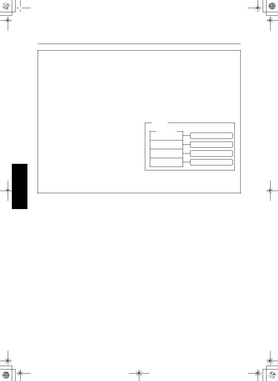
Rhythm and Style
One rhythm of this instrument is comprised of four VARIATION patterns, and for each one the optimum sounds and effects are set.
All of these together comprise one STYLE.
STYLE |
|
|
|
|
|
|
|
||
|
RHYTHM |
|
PANEL setting |
|
VARIATION 1 |
||||
VARIATION 2 |
PANEL setting |
|||
VARIATION 3 |
PANEL setting |
|||
VARIATION 4 |
PANEL setting |
|||
• In the MUSIC STYLIST (page 60) and
MUSIC STYLE ARRANGER (page 62) etc. this STYLE is summoned.
48
QQTG0692
10_Part V.fm 104
Part V Composer
Outline of the Composer
The COMPOSER enables you to create your own accompaniment patterns. A pattern is comprised of 8 parts: DRUMS 1, 2, BASS and ACCOMP1–5 parts. These parts would form the backing of a song.
Rhythm components which can be stored
Different INTRO 1, 2, VARIATION 1 to 4, FILL IN 1, 2 patterns can be created for each MEMORY (A, B, C).
•Each VARIATION is made of a PATTERN, FILL 1 and FILL 2.
•A Maj (major) and Min (minor) pattern is available for each of the INTRO and ENDING 1 and 2.
INTRO |
VARI 1 |
VARI 2 |
VARI 3 |
VARI 4 |
ENDING |
|
|
|
|
|
|
1 Maj |
PATTERN |
PATTERN |
PATTERN |
PATTERN |
1 Maj |
1 Min |
FILL IN 1 |
FILL IN 1 |
FILL IN 1 |
FILL IN 1 |
1 Min |
2 Maj |
FILL IN 2 |
FILL IN 2 |
FILL IN 2 |
FILL IN 2 |
2 Maj |
2 Min |
|
|
|
|
2 Min |
|
|
|
|
|
|
Memory capacity
Expressed in terms of notes, the total number of notes which can be stored in all the COMPOSER memories is about 13,000. The remaining memory available for recording is shown on the recording display as a percentage (%).
•When “Memory full!” appears on the display no more data can be stored in the COMPOSER.
MEMORY
Because the contents of the MEMORY are erased after the power is turned off, you should save the data on disks/SD cards if you wish to keep it. (Refer to pages 125, 140.)
Composer
104
QQTG0692
 14_Part IX.fm 155
Part IX Reverb & Effect
Outline of the
Reverb & Effect
In the REVERB & EFFECT mode, you can make detailed settings related to this instrument’s effects.
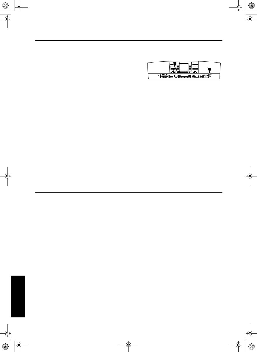
1.Press the PROGRAM MENUS button to turn it on.
PROGRAM
MENUS
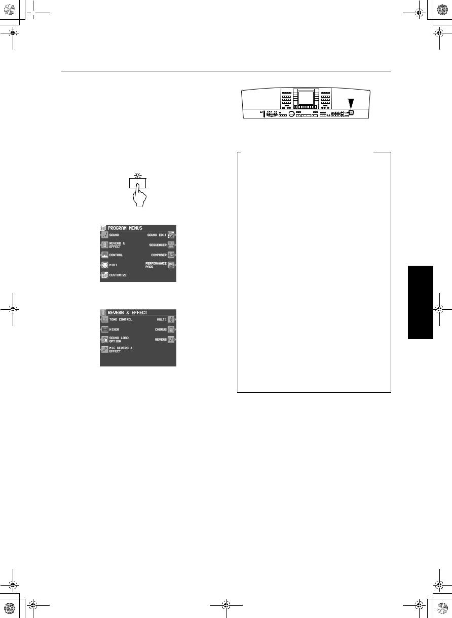
• The display looks similar to the following.
2. Select REVERB & EFFECT.
• The display looks similar to the following.
3.Select the desired menu.
4.Follow the procedures on the corresponding
menu display.
•When the TEMPO/PROGRAM indicator is lit, it indicates that the TEMPO/PROGRAM is available for setting the current function.
5.When you have finished setting the functions, press the PROGRAM MENUS button to turn it off.
Summary of the REVERB & EFFECT menu items
TONE CONTROL (page 156)
Settings for the entire instrument’s final output sound quality.
REVERB:
REVERB type and detailed settings (page 43)
CHORUS:
CHORUS type and detailed settings (page 43)
MULTI:
MULTI EFFECT type and detailed settings (page 42)
MIC REVERB & EFFECT:
Settings for the effects that are applied to MIC. (page 44)
SOUND LOAD OPTION:
Specify whether the various data accompanying a sound, such as effects, are used when the sound is recalled. (page 153)
MIXER:
Use the MIXER display to visually adjust the major settings of each part. (page 150)
Reverb & Effect
155
QQTG0692
 14_Part IX.fm 156
Part IX |
Reverb & Effect |
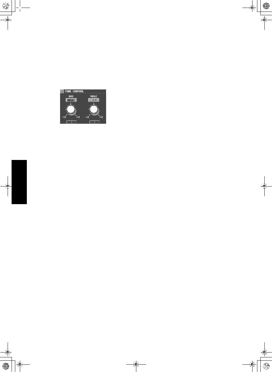
Tone Control
Settings for the entire instrument’s final output sound quality.
1. On the REVERB & EFFECT display, select TONE CONTROL.
• The display looks similar to the following.
2.Use the BASS and buttons to adjust the low range and the TREBLE and buttons
for the high range.
•Raising the settings excessively may cause distorted sounds. Lower the setting or the MAIN VOLUME.
Reverb & Effect
156
QQTG0692

 15_Part X.fm 157
Part X Sound Edit
Outline of the Sound Edit
SOUND EDIT enables you to create your own new sound by altering one of the this instrument’s preset sounds. Your new sound can be stored in one of the sound memory locations. SOUND EDIT has two methods of use. You can edit in detail using functions more commonly associated with a synthesizer, or you can use EASY EDIT which allows you to change some basic parameters on one page.
1.Select a sound to edit.
2.Turn on the PROGRAM MENUS button.
PROGRAM
MENUS
• The display looks similar to the following.
3. Select SOUND EDIT.
• The display looks similar to the following.
4. Select the desired menu and follow the procedures on the corresponding setting display.
•To check the sound of a single tone, press the SOLO button to highlight the SOLO indication. Only the currently selected tone sounds when a key is played.
•When the TEMPO/PROGRAM indicator is lit, it indicates that the TEMPO/PROGRAM is available for setting the current function.
5.When the sound is just the way you like it, on the SOUND EDIT MENU display press the WRITE button to store your new sound.
•Press the EDITED (or ORIGINAL) button to switch between the modified sound (EDITED) and the original sound (ORIGINAL). This allows you to compare the edited sound to the original sound as you are modifying it.
Summary of the SOUND EDIT menu items
EASY EDIT (page 158)
The most often used edit functions—such as brightness and attack speed—are assembled on one display for easy sound modification.
TONE (page 159)
Modify the tones which make up the sound.
PITCH (page 162)
Adjust the settings related to the pitch.
FILTER (page 163)
Adjust the amount of frequency cut in specific frequency ranges.
AMPLITUDE (page 165)
Volume settings.
LFO (page 167)
Cyclic modulation settings.
EFFECT (page 168)
Settings related to the various effects applied to the sound.
CONTROLLER (page 169)
Specify how wheel operation etc. affects the sound.
157
Sound Edit
QQTG0692
 15_Part X.fm 158
Sound Edit
Part X |
Sound Edit |
•When DRUM KIT sounds are selected and the SOUND EDIT is activated, the setting display looks different from that for other sounds, but the basic operation is the same. (To specify
the percussion instrument you wish to edit, use the and buttons to select the sound name, or alternatively, while pressing the keyboard key for the corresponding sound, press the NOTE SELECT button.)
•To record the DIGITAL DRAWBAR settings, first adjust the settings, then enter the SOUND EDIT mode, press the WRITE button and follow the procedure on the display.
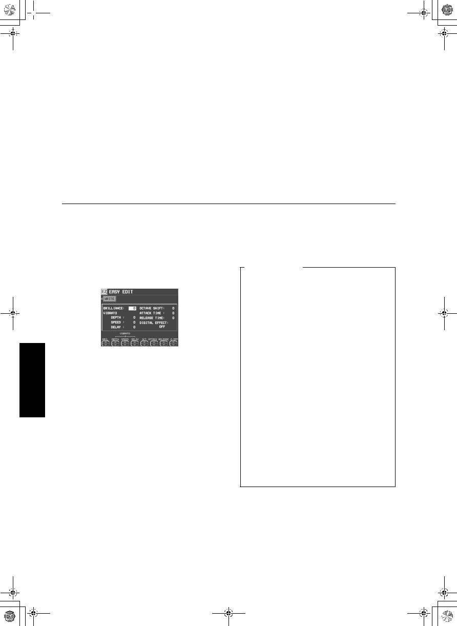
Easy Edit
The most commonly used edit functions are consolidated on one display, providing convenient and quick editing operation.
1. On the SOUND EDIT menu display, select EASY EDIT.
• The display changes to the following.
2. Use the buttons below the display to specify the value of the attribute.
•An effect may remain unchanged when EASY EDIT is used to set the value, if another EDIT function was first used to set the value to its upper or lower limit.
3. Press the WRITE button to store your new sound.
•Storing your new sound is explained on page 169.
•If a sound is stored in the EASY EDIT mode, and is later selected in the EASY EDIT mode, the displayed value of an attribute may be different from the value when it was stored. The sound itself, however, is exactly as it was stored.
Easy Edit items
BRILLIANCE:
Adjust the brightness of the sound.
VIBRATO DEPTH:
Set vibrato depth.
VIBRATO SPEED:
Set vibrato speed.
VIBRATO DELAY:
Set time delay between key played and vibrato start.
OCT SHIFT:
Shift the octave range.
ATTACK:
Adjust attack time.
RELEASE:
Adjust time of sound fade-out after key is released.
D. EFF:
Select type of effect. (Refer to page 168)
158
QQTG0692
 15_Part X.fm 159
Part X |
Sound Edit |
Tone Edit
Modify the separate tones which comprise the sound.
About tones
A sound may be made up of at most four tones.
1st tone
2nd tone
SOUND
3rd tone
•A special process is used to produce realsounding piano type tones. For this reason, some edit procedures for piano sounds, FILTER or AMPLITUDE for example, may differ from those for other sounds.
4th tone
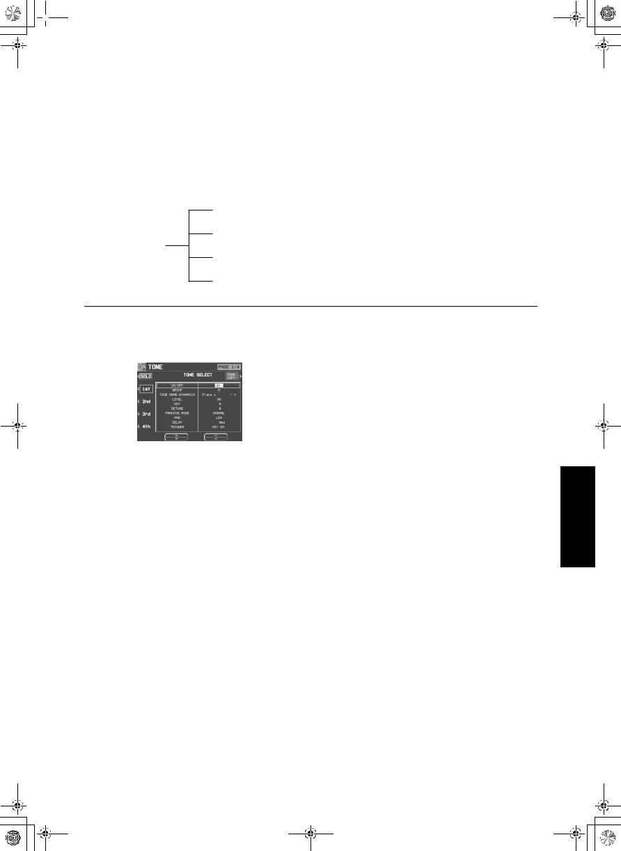
TONE SELECT
1. On the SOUND EDIT menu, select TONE.
• The display looks similar to the following.
2. Use the buttons to the left of the display to select the tone you wish to edit (1st, 2nd, 3rd, 4th).
•Use the ▲ and ▼ buttons to select a setting item and then the and buttons to specify a selection.
•Use the ON/OFF buttons to select ON or OFF.
3. Select a sound for the tone.
•Use the GROUP and buttons to select the group, and the TONE NAME and buttons to select the sound.
•A “ ” mark in the DYNAMICS column indicates that a TONE DYNAMICS change was made to the sound.
4.Use the LEVEL and buttons to adjust the volume.
5.Use the KEY and buttons to set the pitch of the output sound.
6.Use the DETUNE and buttons for fine adjustment of the pitch deviation.
7. Use the PANNING MODE and buttons to select mode. (NORMAL, RANDOM, STEREO R, STEREO L)
•If STEREO R or STEREO L is selected for the MODE, the balance is fixed (cannot be moved).
8. Use the PAN and buttons to adjust the stereo balance.
•CTR is the center point. At L64, the sound is all the way to the left, at R63 all the way to the right.
9. Use the DELAY and buttons to adjust the delay time of the sound.
•The higher the number, the longer the delay before sound output.
10.Use the TRIGGER and buttons to select a trigger mode.
KEY ON:
The normal mode, in which sound is emitted when the key is played.
KEY OFF:
Sound is emitted when the key is released (like muted strings, for example).
LEGATO:
Sound is emitted only when the key is played legato.
NON LEG:
Sound is not emitted when the key is played legato.
159
Sound Edit
QQTG0692
 15_Part X.fm 160
Sound Edit
Part X |
Sound Edit |
PEDAL:
The sound is produced only while the SUSTAIN button is on.
CHORD:
The sound is emphasized when chords are played (like the cutting sound of a guitar, for example).
TONE COPY
You can copy the tone of a particular sound to a specified tone in the sound you are editing.
1.On the 1/4 display, press the TONE COPY button.
2.Use the FROM and buttons to select the tone to copy from.
•Use the OPTION and buttons to select the item you wish to copy.
3.Use the TO and buttons to select the tone you wish to copy to.
4.Press the OK button.
• Tone copy is executed.
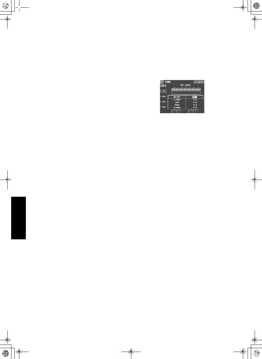
KEY LAYER
Adjust the relation of tone output to keyboard location.
1. Use the PAGE buttons to view the 2/4 display.
• The display looks similar to the following.
2. Use the buttons to the left of the display to select a tone (1st, 2nd, 3rd or 4th).
•Use the ▲ and ▼ buttons to select a setting item and then the and buttons to specify a selection.
3.Use the L-FADE and buttons and the LOW and buttons to define the area of the
lower range of tone output.
•By entering different values for the L-FADE and LOW settings, you can define a sloping volume increase to the peak output volume which corresponds to the note pitch.
4.Use the HIGH and buttons and the H- FADE and buttons to define the area of
the higher range of tone output.
•By entering different values for the H-FADE and HIGH settings, you can define a sloping volume decrease from the peak output which corresponds to the note pitch.
•By overlapping the L-FADE and H-FADE curves of each different tone, you can achieve a cross-fade effect, where the sound gradually changes in relation to pitch.
5.Repeat steps 2 to 4 for the other tones, as desired.
160
QQTG0692
 15_Part X.fm 161
Part X |
Sound Edit |
VELOCITY LAYER
Adjust these settings to regulate the tone output relative to the velocity.
1. Use the PAGE buttons to view the 3/4 display.
• The display looks similar to the following.
2. Use the buttons to the left of the display to select a tone (1st, 2nd, 3rd or 4th).
•Use the ▲ and ▼ buttons to select a setting item and then the and buttons to specify a selection.
3.Use the L-FADE and buttons and the LOW and buttons to define the pp sound output area for the lower range.
4.Use the HIGH and buttons and the H- FADE and buttons to define the ff sound
output area for the higher range.
•By overlapping the L-FADE and H-FADE curves of each different tone, you can change the way the tone sounds relative to how hard or softly the keyboard is played.
5.Repeat steps 2 to 4 for the other tones, as desired.
TONE DYNAMICS
You can adjust the settings so that a different sound (tone) is output for each tone depending on the velocity (how hard the keys are played).
1. Use the PAGE buttons to view the 4/4 display.
• The display looks similar to the following.
2.Use the buttons to the left of the display to select a tone.
3.Use the ▲ and ▼ buttons to select the column for the function you wish to adjust.
4.Select the tone waveform.
•Use the GR and buttons to select the sound group. Use the TONE WAVEFORM and buttons to select the waveform.
5.Use the LEV and buttons to adjust the volume. Use the FLT and buttons to set the sound.
6.Use the VELOCITY and buttons to specify
the velocity range.
•When the upper limit of a waveform is set to 127, no more waveforms can be added.
7.Repeat steps 3 to 6 to edit the other waveforms, as desired.
8.Repeat steps 2 to 7 for the other tones, as desired.
Sound Edit
161
QQTG0692
 15_Part X.fm 162
Sound Edit
Part X |
Sound Edit |
Pitch Edit
Adjust the settings related to the pitch of the sound.
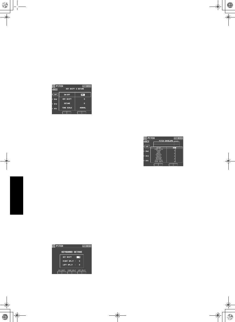
KEY SHIFT & DETUNE
1. On the SOUND EDIT menu display, select PITCH.
• The display looks similar to the following.
2. Use the buttons to the left of the display to select a tone (1st, 2nd, 3rd or 4th).
•Use the ▲ and ▼ buttons to select a setting item and then the and buttons to specify a selection.
3. Use the KEY SHIFT and buttons to specify the output pitch.
• Units are in semitones.
4. Use the DETUNE and buttons to fineadjust the pitch.
•Slight differences in the DETUNE values between the tones add fullness to the sound.
5. Use the TONE SCALE and buttons to select the type of scale (NORMAL, 1/2, 1/4, 1/8, 1/16, 1/32, 1/64, FIX).
•NORMAL is the normal scale type. For example, when 1/2 is selected, a difference in pitch between one key and the adjacent key becomes half the normal pitch difference. When FIX is selected, the pitch is the same regardless of which key is played.
KEYBOARD OCTAVE
1. Use the PAGE buttons to view the 2/4 display.
• The display looks similar to the following.
3.Use the RIGHT SPLIT and buttons to set the octave of the right part when the keyboard is split.
4.Use the LEFT SPLIT and buttons to set the octave of the left part when the keyboard is split.
PITCH ENVELOPE
Specify how the pitch changes over time, from the time the key is played to the time the sound dies out.
1. Use the PAGE buttons to view the 3/4 display.
• The display looks similar to the following.
2. Use the buttons to the left of the display to select a tone.
•Use the ▲ and ▼ buttons to select a setting item and then the and buttons to specify a selection.
3. Adjust the settings for the pitch change envelope.
•Use the buttons below the display to set the corresponding values. The envelope is created on the display as you input the settings.
•Use the TOTAL DEPTH and buttons to specify the maximum level.
•Use the START PITCH and buttons to set the start point. Use the STOP PITCH and buttons to set the stop point.
4.Repeat steps 2 and 3 for the other tones, as desired.
2.Use the OCT SHIFT and buttons to set the octave of the sound.
162
QQTG0692
 15_Part X.fm 163
Part X |
Sound Edit |
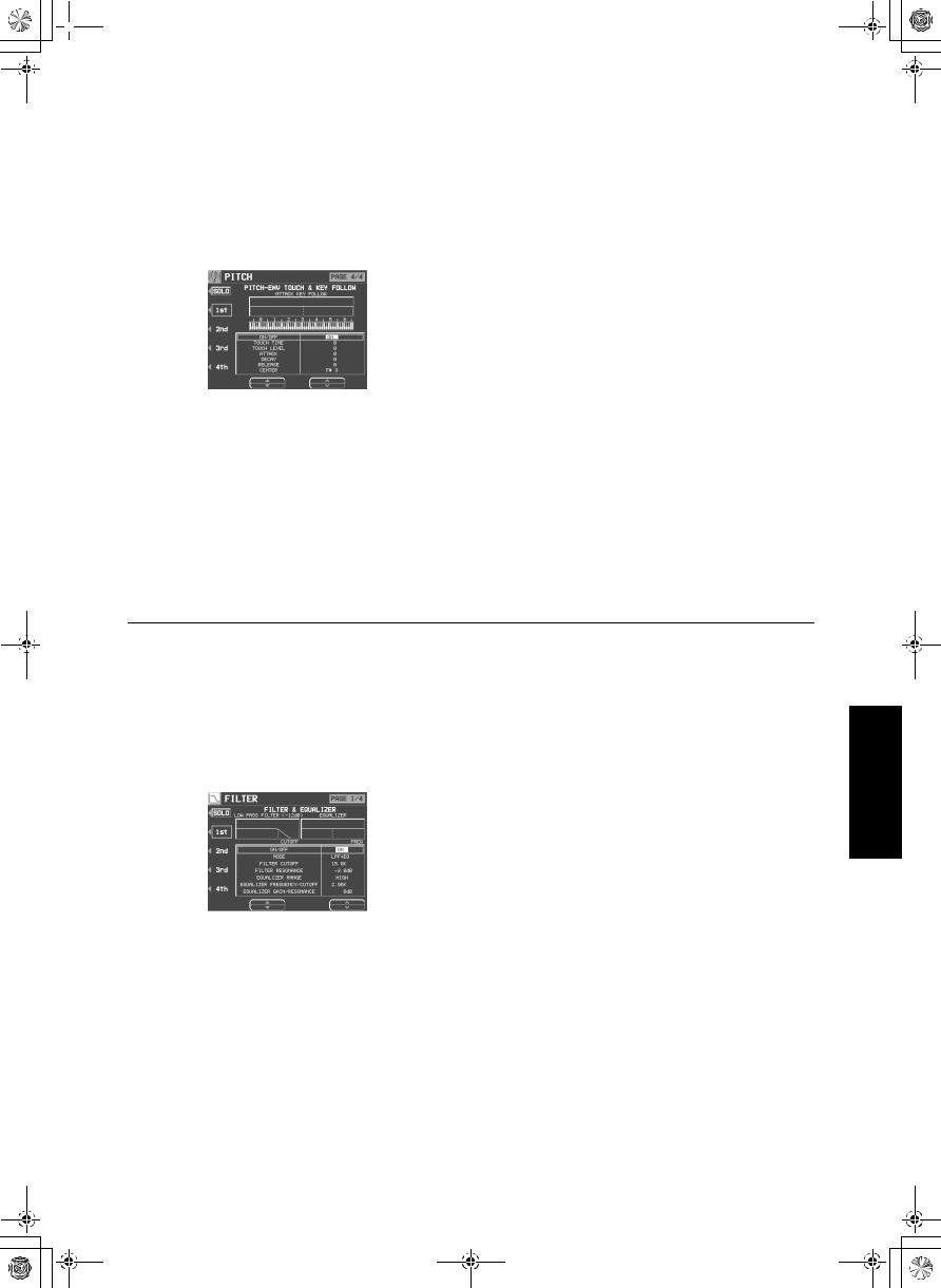
PITCH ENVELOPE TOUCH & KEY FOLLOW
Specify how the pitch envelope changes in relation to note pitch.
1. Use the PAGE buttons to view the 4/4 display.
2. Use the buttons to left of the display to select a tone.
•Use the ▲ and ▼ buttons to select a setting item and then the and buttons to specify a selection.
3.Use the TOUCH and buttons to change the respective touch settings.
•Use the TIME and buttons to specify the
time change depending on touch. Use the LEVEL and buttons to specify the pitch change level depending on touch.
•At a − setting, the softer the keys are pressed, the greater the change. At a + setting, the harder the keys are pressed, the greater the change.
4.Change the key follow settings for the ATTACK, DECAY and RELEASE.
•Use the and buttons corresponding to the
ENVELOPE KEY FOLLOW attributes to adjust the settings. Use the CENTER and buttons to select the center of the bend direction.
Filter Edit
Make major changes to the sound by eliminating specific frequency ranges.
FILTER & EQUALIZER
1. On the SOUND EDIT menu, select FILTER.
• The display looks similar to the following.
2. Use the buttons to the left of the display to select a tone.
•Use the ▲ and ▼ buttons to select a setting item and then the and buttons to specify a selection.
3. Use the MODE button to select the filter mode.
LPF(6)+EQ (low-pass filter + equalizer)
Signals higher than the cut-off frequency are cut. Normal sounds are softened.
HPF(6)+EQ (high-pass filter + equalizer)
Signals lower than the cut-off frequency are cut. Normal sounds are sharpened.
LPF24 (low-pass filter 24)
A stronger low-pass filter than LPF+EQ.
HPF24 (high-pass filter 24)
A stronger high-pass filter than HPF+EQ.
BPF (band-pass filter)
Cuts off signals that are not within in the area between the two specified CUTOFF frequencies.
•For this mode, adjust the settings on the EQUALIZER/FILTER side as well.
THRU
No filter effect is applied.
163
Sound Edit
QQTG0692
 15_Part X.fm 164
Sound Edit
Part X |
Sound Edit |
4.Use the CUTOFF and buttons to set the frequency range which is cut by the filter.
5.Use the RESONANCE and buttons to
specify the resonance value (dB).
•Resonance is effect which adds character to the sound by emphasizing the harmonic components of frequencies close to the cut-off frequency.
<Equalizer>
For LPF(6)+EQ/HPF(6)+EQ filters, the sound quality can be modified by the EQUALIZER.
RANGE
Select the setting range (HIGH or LOW).
FREQUENCY
Set the standard frequency.
GAIN
Set the level increase or decrease from the value set for FREQ (dB).
6. Repeat steps 2 to 5 for each tone, as desired.
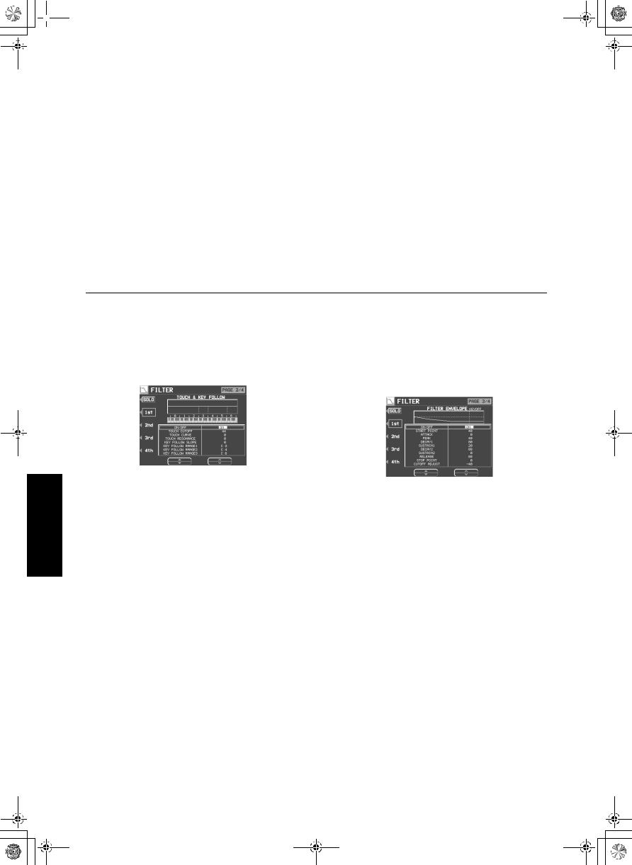
TOUCH & KEY FOLLOW
Adjust how the filter is applied relative to touch and pitch.
1. Use the PAGE buttons to view the 2/4 display.
• The display looks similar to the following.
2. Use the buttons to the left of the display to select a tone.
•Use the ▲ and ▼ buttons to select a setting item and then the and buttons to specify a selection.
3.Modify how the respective filters are applied relative to key touch.
•Use the TOUCH CUT OFF and buttons to
specify the amount of change in the cut-off frequency. Use the TOUCH CURVE and
buttons to specify the curve of change. Use the TOUCH RESONANCE and buttons to specify the degree of change in the resonance value.
4.Modify how the respective filters are applied relative to note pitch.
•Use the KEY FOLLOW SLOPE and but-
tons to adjust the bend slope. Use the KEY FOLLOW RANGE and buttons to specify the pitch range.
5.Repeat steps 2 to 4 for the other tones, as desired.
164
FILTER ENVELOPE
Specify how the filter changes over time, from the time the key is played to the time the sound dies out.
1. Use the PAGE buttons view the 3/4 display.
• The display looks similar to the following.
2. Use the buttons to the left of the display to select a tone.
•Use the ▲ and ▼ buttons to select a setting item and then the and buttons to specify a selection.
3. Use the and buttons to modify the respective filter envelopes.
•Use the buttons below the display to adjust the respective settings.
•You can use the CUTOFF ADJUST buttons to set the total upper and lower settings, the START POINT buttons to set the start point, and the STOP POINT buttons to set the stop point.
4.Repeat steps 2 and 3 for the other tones, as desired.
QQTG0692
 15_Part X.fm 165
Part X |
Sound Edit |
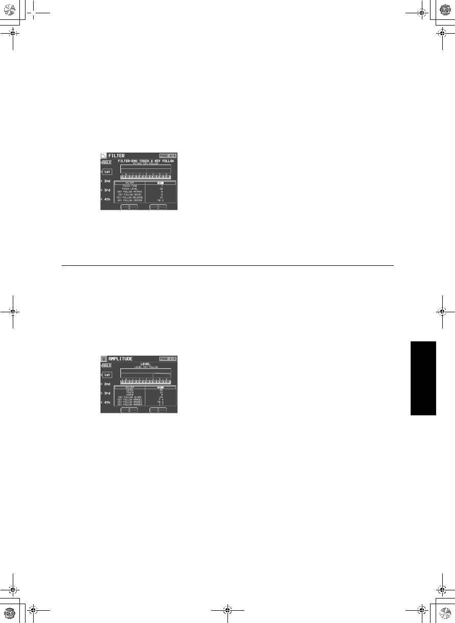
FILTER ENVELOPE TOUCH & KEY FOLLOW
Specify how the filter envelope (curve) changes relative to touch or note pitch.
1. Use the PAGE buttons to view the 4/4 display.
• The display looks similar to the following.
2. Use the buttons to the left of the display to select a tone.
•Use the ▲ and ▼ buttons to select a setting item and then the and buttons to specify a selection.
3.Modify how the respective filter envelopes change relative to touch.
•Use the TOUCH TIME and buttons to
specify the time change, and the TOUCH LEVEL and buttons to specify the level, relative to touch.
•At a − setting, the softer the keys are played, the greater the change. At a + setting, the harder the keys are played, the greater the change.
4. Use the KEY FOLLOW and buttons to modify how the respective filter envelopes change relative to note pitch.
•Adjust the respective slopes for attack, decay and release. Use the CENTER and buttons to specify the center of the bend slope by note name.
Amplitude Edit
Adjust the settings related to the volume of the sound.
LEVEL
1. On the SOUND EDIT menu, select AMPLITUDE.
• The display looks similar to the following.
2. Use the buttons to the left of the display to select a tone.
•Use the ▲ and ▼ buttons to select a setting item and then the and buttons to specify a selection.
3.Use the LEVEL and buttons to select the volume.
4.Use the TOUCH and buttons to set the amount of volume change in relation to how
hard the keyboard is played.
•At a − value, the softer the keyboard is played, the louder the sound. At a + value, the harder the keyboard is played, the louder the sound.
5.Use the CURVE and buttons to select the type of volume curve depending on touch.
6.Change the respective key follow settings.
•Use the KEY FOLLOW SLOPE and but-
tons to adjust the bend slope. Use the KEY FOLLOW RANGE (1–3) and buttons to specify the pitch range by note name.
7.Repeat steps 2 to 6 for the other tones, as desired.
165
Sound Edit
QQTG0692
 15_Part X.fm 166
Sound Edit
Part X |
Sound Edit |
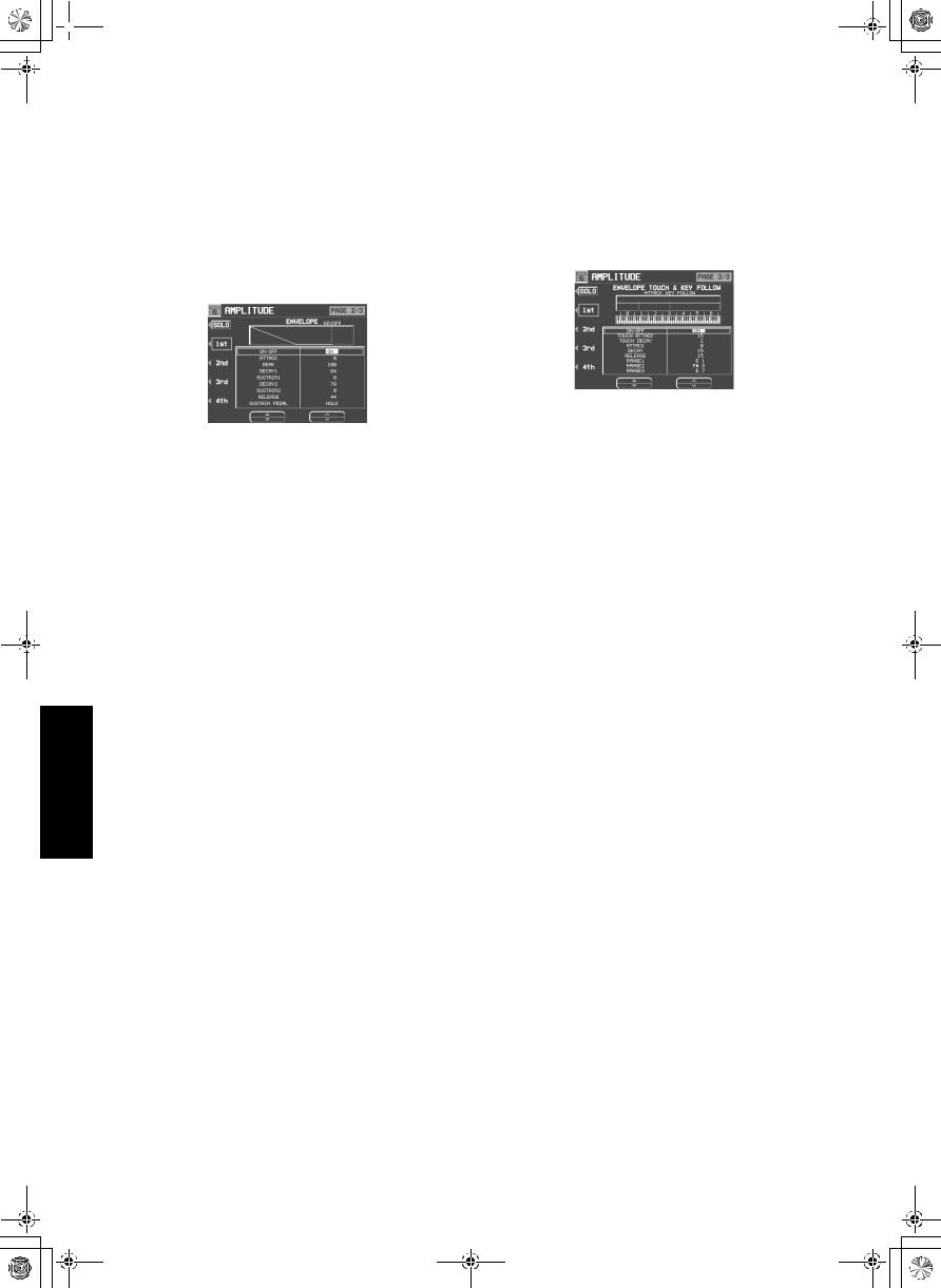
ENVELOPE
Specify how the volume changes over time, from the time the key is played to the time the sound dies out.
1. Use the PAGE buttons to view the 2/3 display.
• The display looks similar to the following.
2. Use the buttons to the left of the display to select a tone.
•Use the ▲ and ▼ buttons to select a setting item and then the and buttons to specify a selection.
3. Adjust the settings for the volume envelope.
•Use the buttons below the display to set the corresponding values. The envelope is created on the display as you input the settings.
•Use the SUSTAIN PEDAL and buttons to select the type of sustain.
LONG:
Extend the release time of the sound. HOLD:
Maintain the key-pressed condition.
4.Repeat steps 2 and 3 for the other tones, as desired.
ENVELOPE TOUCH & KEY FOLLOW
Specify how the volume changes relative to touch or note pitch over time.
1. Use the PAGE buttons to view the 3/3 display.
2. Use the buttons to the left of the display to select a tone.
•Use the ▲ and ▼ buttons to select a setting item and then the and buttons to specify a selection.
3. Change the touch settings.
•Use the TOUCH ATTACK and buttons to
specify the ATTACK time change depending on touch. Use the TOUCH DECAY and buttons to specify the DECAY time change depending on touch.
•At a − setting, the softer the keys are pressed, the greater the change. At a + setting, the harder the keys are pressed, the greater the change.
4. Change the key follow settings for the ATTACK, DECAY and RELEASE.
•Use the RANGE buttons to specify the keyboard range.
166
QQTG0692
 15_Part X.fm 167
Part X |
Sound Edit |
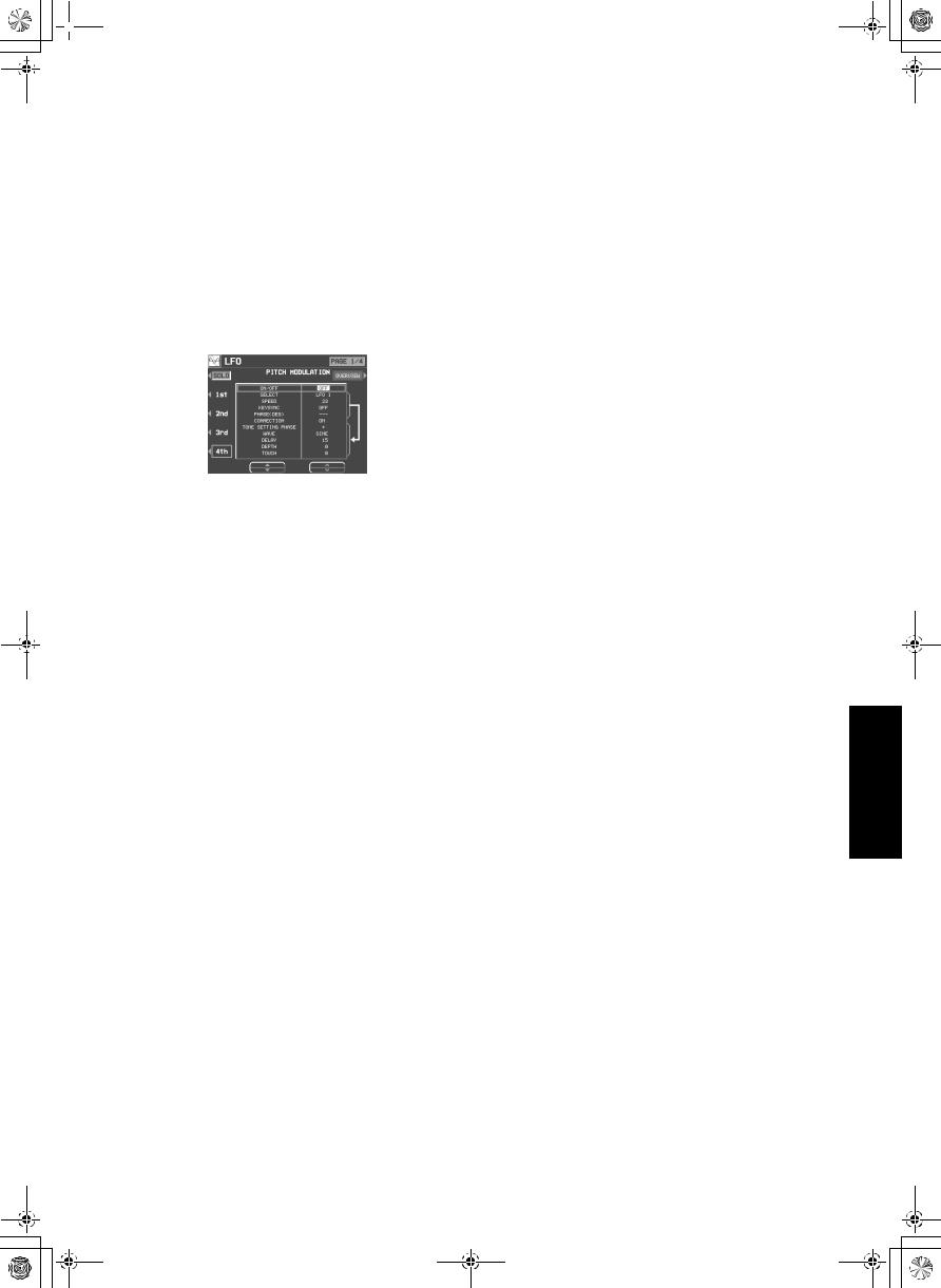
LFO Edit
LFO can be applied to the pitch, amplitude, filter and/or pan to produce a cyclic modulation of the sound.
• Twelve LFO groups can be used.
LFO
1. On the SOUND EDIT MENU display, select LFO.
• The display looks similar to the following.
2.Use the PAGE buttons to select the respective characteristics.
PAGE 1/4: PITCH (vibrato effect) PAGE 2/4: AMPLITUDE (tremolo effect) PAGE 3/4: FILTER (wah-wah effect) PAGE 4/4: PANNING (auto pan effect)
3.Use the buttons to the left of the display to select a tone.
4.Adjust the respective assigned LFO’s.
•LFO which share the same number on other displays are also changed with this adjustment.
SELECT
Select the assigned LFO number (1 to 12)
SPEED
Adjust the modulation speed.
KEYSYNC
When playing more than one note, specify whether the LFO starts or not each time a key is pressed (ON/OFF).
•When KEYSYNC is set to ON: if, while playing one note, you play a second note, the LFO is applied to the second note as well.
PHASE
Degree of phase change.
5. Use the CONNECTION buttons to specify whether or not the LFO is applied to the tone.
•An arrow mark indicates that the LFO is applied.
6.Use the TONE SETTINGS and buttons to adjust the respective parameters.
PHASE
Phase
•A + indicates normal phase, and a − indicates an inverted phase.
WAVE
Modulate the waveform.
SINE: Sine wave
TRIANGLE: Triangle wave
SQUARE: Square wave
SAW TOOTH: Saw tooth wave
RANDOM: Irregular pattern
DELAY
Delay time is the time elapsed from when the keyboard key is pressed until the modulation begins.
DEPTH
Modulation depth
TOUCH
Degree of modulation change in relation to touch
7. Repeat steps 2 to 6 for the other tones, as desired.
•You can press the OVERVIEW button to confirm the status of each LFO setting.
167
Sound Edit
QQTG0692
 15_Part X.fm 168
Part X |
Sound Edit |
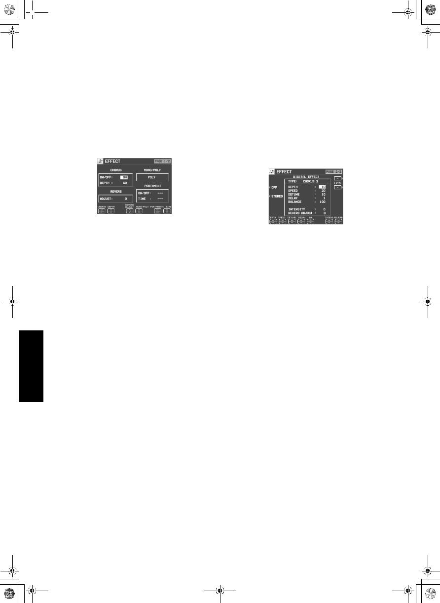
Effect Edit
These are settings related to the various effects applied to your edited sound.
EFFECT
1. On the SOUND EDIT menu display, select EFFECT.
• The display looks similar to the following.
DIGITAL EFFECT
1. Use the PAGE buttons to view the 2/2 display.
•The display looks similar to the following.
•The display for the effect type which is bestsuited for the sound currently being edited is selected.
2.Use the CHORUS ON/OFF buttons set CHORUS to on or off. Use the respective DEPTH and buttons to specify how the CHORUS is applied.
3.Use the REVERB ADJUST and buttons to specify how the REVERB is applied.
4.Use the MONO/POLY and buttons to select the sound output mode.
5.Use the PORTAMENTO ON/OFF buttons set portamento to on or off. Use the TIME and buttons to set the portamento time.
Sound Edit
168
2.Use the TYPE and buttons to select the type of effect.
<ON/OFF button>
Specify whether the DIGITAL EFFECT button turns on or off when the sound is selected. When set to ON, the DIGITAL EFFECT button turns on automatically when the sound is selected.
<STEREO/MONO button>
Select stereo (STEREO) or monaural (MONO) output of the effect.
3.Use the buttons along the bottom of the display to select the attribute you wish to adjust.
•When the type is changed, the parameters revert to the factory defaults.
QQTG0692
 15_Part X.fm 169
Part X |
Sound Edit |
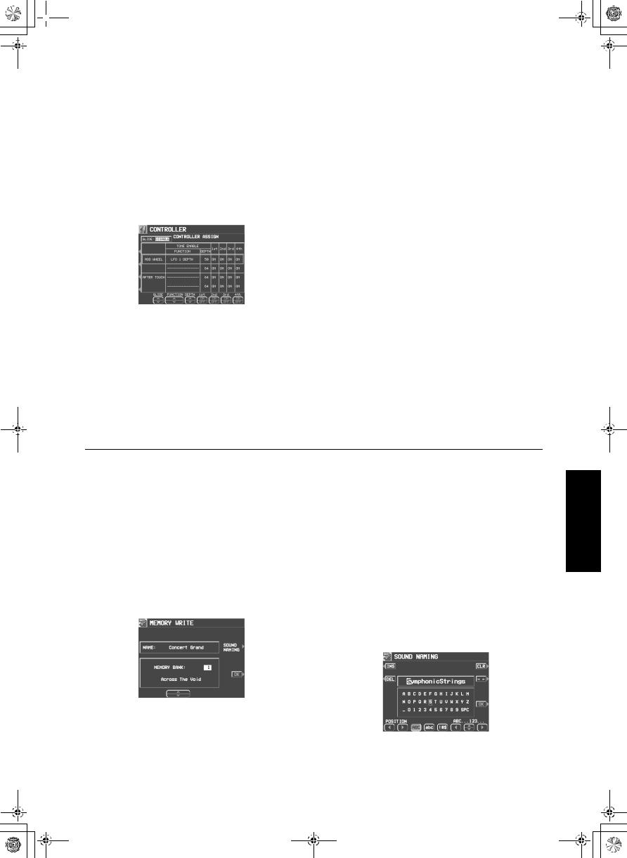
Controller Edit
Specify how operation of the controllers, such as the wheels, etc., affects the sound.
CONTROLLER
1. On the SOUND EDIT menu display, select CONTROLLER.
• The display looks similar to the following.
2. Use the buttons to the left of the display to select a controller.
•Two functions can be assigned to each controller.
3.Use the FUNCTION and buttons to select a function for the controller.
4.Use the DEPTH and buttons to set the depth of the function applied by the controller.
5. Use the ON/OFF and buttons to set the controller to on or off for each tone.
•When set to INV, the effect is applied inversely.
6.Repeat steps 2 to 5 for the other controllers, as desired.
7.Use the GLIDE and buttons to select whether or not the glide effect is active.
ENABLE:
The glide effect is enabled.
DISABLE:
The glide effect is disabled.
•To assigning a function to the foot switch, refer to page 172.
Store the new sound
The MEMORY button in the SOUND GROUP section accesses memory banks reserved for the sounds you create with the SOUND EDIT. You can store up to 40 original sounds then select the sounds just like the other sounds in the SOUND GROUP.
Procedure
1. When you have edited the sound to just the way you like it, on the SOUND EDIT menu display press the WRITE button.
•The display changes to the MEMORY WRITE display.
2. To assign a name to your new sound, press the SOUND NAMING button.
•If you do not assign a name to your sound, the name becomes the same as the original sound from which you started. In this case, skip to step 5.
•The display changes to the SOUND NAMING display.
169
Sound Edit
QQTG0692
 15_Part X.fm 170
Part X |
Sound Edit |
3. Use the buttons below the display to assign a name.
•Set the character input position with the POSITION buttons, select the characters with the alphanumeric buttons and repeat name assignment.
•Switch from upper to lower case letters with the ABC, abc button.
•Press the INS button to enter a space at the cursor position.
•Press the DEL button to erase the character at the cursor position.
•Press the CLR button to erase the entire name.
•Press the →← button to center the name.
4. When you have finished typing the name, press the OK button.
•The display returns to the MEMORY WRITE display.
5.Use the and buttons to select the MEMORY number in which to store the new sound (1–40).
6.Press the OK button.
•The new sound is stored, and “COMPLETED!” is shown on the display.
•The SOUND EDIT mode is turned off.
•The stored sound memories can be saved on a disk/an SD card for recall at a later time. (Refer to pages 125, 140.)
Sound Edit
Select a new sound
You can select your original sound just like the other sounds in the SOUND GROUP.
1.In the SOUND GROUP section, press the MEMORY button.
MEMORY
• The list of sounds is shown on the display.
2.Select the desired sound from the list on the display.
170
QQTG0692
 16_Part XI.fm 171
Part XI Control
Outline of Control functions
Various settings related to the operation of this instrument are adjusted with the CONTROL functions.
1.Press the PROGRAM MENUS button to turn it on.
PROGRAM
MENUS
• The display looks similar to the following.
2. Select CONTROL.
• The display looks similar to the following.
3. Select a function.
INITIAL
Return the settings and memories to the factory-preset status. (Refer to page 186.)
OVERALL TOUCH SENSITIVITY (page 172) Adjust the amount of keyboard touch response.
FOOT CONTROLLERS (page 172)
Assign functions to the separately sold Foot Switch and Foot Controller, etc.
PANEL MEMORY MODE
Define which panel settings are stored when the PANEL MEMORY is used. (Refer to page 66.)
MUSIC STYLE ARRANGER MODE
Define which panel settings change by pressing a FILL IN button when the MUSIC STYLE ARRANGER is used. (Refer to page 63.)
FADE IN/OUT SETTING
Settings related to the FADE IN/FADE OUT. (Refer to page 58.)
4. Follow the procedure to adjust the settings.
•While you are adjusting the settings, when the TEMPO/PROGRAM indicator is lit, it indicates that the TEMPO/PROGRAM is available for setting the current function.
5.When you have finished setting the functions, press the PROGRAM MENUS button to turn it off.
171
Control
QQTG0692

 16_Part XI.fm 172
Control
Part XI |
Control |
Overall Touch Sensitivity
This instrument features INITIAL TOUCH (the volume, for example, changes depending on how hard the keyboard is played).
1. On the CONTROL MENU display, select OVERALL TOUCH SENSITIVITY.
• The display looks similar to the following.
2. Use the and buttons to adjust the amount of keyboard touch response (0 to 9).
•When set to 0, initial touch sensitivity is turned off.
Foot Controllers
If an optional Foot Switch and/or Expression Pedal (sold separately) is connected, you can assign it one of several functions, allowing convenient and fast control during your performance.
1. On the CONTROL MENU display, select FOOT CONTROLLERS.
• The display looks similar to the following.
2.Use the CONTROLLER ▲ and ▼ buttons to select a switch name, and the FUNCTION and buttons to select its function.
FOOT SWITCH
OFF:
No function is assigned.
SOFT PEDAL:
Soft on/off
SOSTENUTO PEDAL:
Sostenuto on/off
P.MEM INCREMENT:
Increment the PANEL MEMORY number selection by 1.
P.MEM DECREMENT:
Decrement the PANEL MEMORY number selection by 1.
P. MEM BANK INC.:
Change to the next PANEL MEMORY bank in order.
P. MEM BANK DEC.:
Change to the previous PANEL MEMORY bank in order.
172
QQTG0692
 16_Part XI.fm 173
Part XI |
Control |
PANEL MEMORY 1 to 8:
The specified PANEL MEMORY number is turned on.
P.MEM INC.+DEC.:
Press the switch to increment the PANEL MEMORY number selection by one; release the switch to return to the previous number.
START/STOP:
START/STOP button on/off
FILL IN 1:
FILL IN 1 button on
FILL IN 2:
FILL IN 2 button on
INTRO & ENDING 1:
INTRO & ENDING 1 button on
INTRO & ENDING 2:
INTRO & ENDING 2 button on
SUSTAIN:
SUSTAIN button on/off
GLIDE:
Glide on/off (The glide effect “bends” the pitch down by about one semitone.)
TECHNI-CHORD:
TECHNI-CHORD button on/off
DIGITAL EFFECT:
DIGITAL EFFECT button on/off
MULTI EFFECT:
MULTI EFFECT button on/off
ROTARY SLOW/FAST:
TREMOLO SLOW/FAST of the DIGITAL
DRAWBAR
MIC REVERB:
MIC REVERB button on
MIC EFFECT:
MIC EFFECT button on
PUNCH RECORD:
Punch in/punch out
APC HOLD:
Memorize the chord specified for the automatic accompaniment.
FADE IN:
FADE IN button on/off
FADE OUT:
FADE OUT button on/off
PAD 1 to 6:
Specified PERFORMANCE PADS on
TAP TEMPO:
TAP TEMPO button on.
EXPRESS. PEDAL
TOTAL EXPRESSION:
The volume for all parts changes when the expression pedal is operated.
PART EXPRESSION:
The volume changes only for parts for which PART EXP PEDAL was turned ON on the PART SETTING display for SOUND. (Refer to page 148.)
• |
The initialized settings are as follows: |
|
|
FOOT SWITCH |
SUSTAIN |
|
|
|
|
EXPRESS. PEDAL |
TOTAL EXPRESSION |
|
|
|
• |
For connection of a Foot Switch, etc., refer to |
|
|
page 188. |
|
173
Control
QQTG0692
 17_Part XII.fm 174
Part XII Customize
Outline of Customize functions
Customize
Many of this instrument’s settings can be customized for maximum playing convenience and ease.
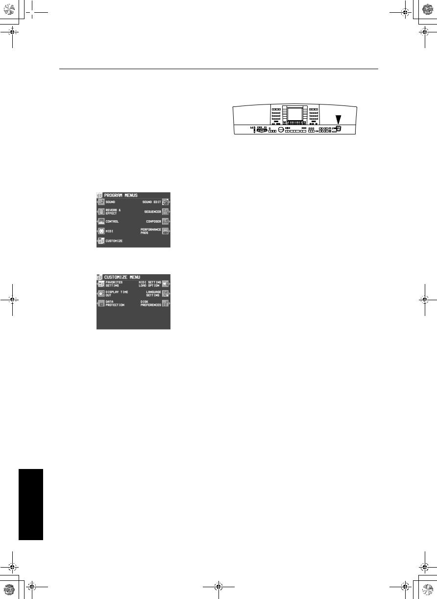
1. Press the PROGRAM MENUS button to turn it on.
• The display looks similar to the following.
2. Select CUSTOMIZE.
• The display looks similar to the following.
DISK PREFERENCES (KN2400)
Automatic display when a floppy disk is inserted (page 130).
SD PREFERENCES (KN2600)
Specify the desired priority of displays when the LOAD button is pressed on the control panel (page 145).
4. Follow the procedure to adjust the settings.
•While you are adjusting the settings, when the TEMPO/PROGRAM indicator is lit, it indicates that the TEMPO/PROGRAM is available for setting the current function.
5.When you have finished setting the functions, press the PROGRAM MENUS button to turn it off.
(KN2400)
3. Select a function.
FAVORITES SETTING
FAVORITES display settings (page 33)
DISPLAY TIME OUT (page 175)
Adjust settings related to the screen display.
DATA PROTECTION (page 176)
Specify when you don’t want the data to change in cases where it normally does, for instance during disk load and when automatic settings are made, etc.
MIDI SETTING LOAD OPTION (page 176) Specify how MIDI data is handled when data is loaded from a disk.
LANGUAGE SETTING
Select your preferred language for the displayed messages.
•The display is different, but the operation is the same as for HELP (page 33).
174
QQTG0692
 17_Part XII.fm 175
Part XII |
Customize |
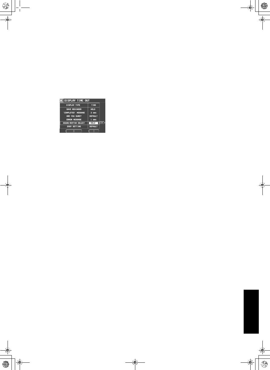
Display Time Out
Numerous message displays and setting displays conveniently guide you through the operation steps of this instrument. Once you become familiar with the operation of your instrument, however, you may wish to shorten or even suspend the display time of the message displays.
1. On the CUSTOMIZE display, select DISPLAY |
4. Press the OK button. |
TIME OUT. |
|
• The display looks similar to the following. |
• Some messages may be displayed even if |
|
they are set to OFF. |
2.Use the DISPLAY TYPE and buttons to select the function.
SAVE REMINDER:
Reminder display (OFF, DEFAULT, HOLD, 1 to 10 sec)
‘COMPLETED’ MESSAGE:
Operation successfully completed (OFF, DEFAULT, HOLD, 1 to 10 sec)
ARE YOU SURE?:
Display requires user action for confirmation (OFF, DEFAULT, HOLD)
ERROR MESSAGE:
Error notification display (DEFAULT, HOLD, 1 to 10 sec)
SOUND/RHYTHM SELECT:
Sound/rhythm and PERFORMANCE PADS BANK selection display (DEFAULT, HOLD, 1 to 10 sec)
EASY SETTING:
Display time when the setting display was accessed pressing and holding a panel button (DEFAULT, HOLD, 1 to 10 sec)
•When set the OFF, the display will not appear.
•When set to DEFAULT, the display time returns to the initialized setting.
•You can specify 1 to 10 seconds for the display time.
•When set to HOLD, the DISPLAY HOLD automatically turns on.
3.Use the TIME and buttons to change the setting.
175
Customize
QQTG0692
 17_Part XII.fm 176
Customize
Part XII |
Customize |
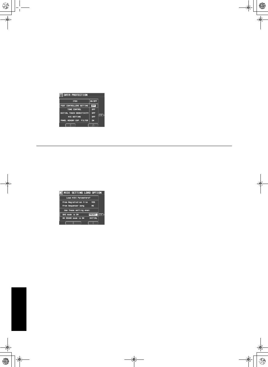
Data Protection
Data which you don’t want to change but which is normally overwritten during disk load, song change, or the automatic setting functions, etc. can be protected from accidental overwriting.
1. In the CUSTOMIZE MENU display, select DATA PROTECTION.
• The display looks similar to the following.
2.Use the ITEM and buttons to select an item.
3.Use the ON/OFF button to select ON or OFF.
ON:
The data is protected and will not be changed.
OFF:
The data is not retained.
4.Repeat steps 2 and 3 for each item.
5.Press the OK button.
MIDI Setting Load Option
Specify how MIDI data is handled when data is loaded from a disk.
1. On the CUSTOMIZE MENU display, select MIDI SETTING LOAD OPTION.
• The display looks similar to the following.
2. Use the ▲ and ▼ buttons to select an item.
Load MIDI Parameters?
From Registration file:
Specify whether MIDI data is also loaded when panel data is loaded (NO/YES).
From Sequencer Song:
Specify whether MIDI data is loaded or changed when SEQUENCER data is loaded or when the SONG is changed by the SEQUENCER SONG SELECT, SONG COPY or TRACK ASSIGN (NO/YES).
•The MIDI settings are always stored at the start of each recorded SEQUENCER SONG and when PANEL WRITE is executed. In the initialized state, the MIDI settings are not loaded even when the SONG is changed. However, changing this setting to YES will cause the stored MIDI settings to also load in these cases.
Use these settings when:
GM2 mode ON:
Specify how the MIDI settings of this instrument are affected when GM2 is on.
•Select from INITIAL, (initialized settings), PRESET (MIDI PRESETS), and KEEP (the settings do not change).
NX SOUND mode ON:
Specify how the MIDI settings of this instrument are affected when NX SOUND is ON.
•Select from INITIAL, (initialized settings), PRESET (MIDI PRESETS), and KEEP (the settings do not change).
3.Use the and buttons to change the setting.
4.Press the OK button.
176
QQTG0692
 18_Part XIII.fm 177
Part XIII MIDI
What is MIDI?
MIDI (Musical Instrument Digital Interface) is the international standard for digital communication of electronic musical instrument data. This means that any equipment which has a MIDI terminal—such as electronic musical instruments and personal computers—can easily exchange digital data with other MIDI equipment without resorting to complicated conversions or connections.
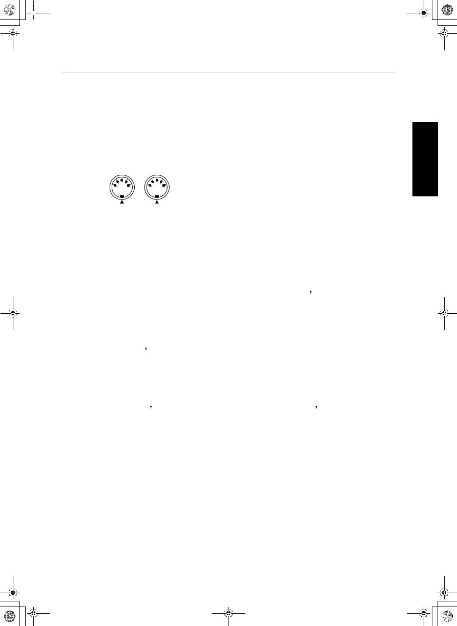
MIDI terminals
(On the rear panel) |
|
|
IN: |
|
|
|
|
|
The terminal by which this instrument receives |
|
|
|
|
data from other equipment. |
|
|
|
|
OUT: |
|
|
|
|
The terminal that transmits data from this |
|
|
|
|
instrument to other equipment. |
|
OUT |
MIDI |
IN |
|
|
|
|
• For these connections, use a commercially |
|
|
|
|
||
|
|
|
|
|
|
|
|
|
available MIDI cable. |
Connection examples
To generate sound from a connected instrument by playing this instrument
|
|
|
OUT |
MIDI cable |
|
|
IN |
||
|
|
|
|
|
|
||||
|
|
|
|
|
|
|
|
|
|
|
This instrument |
|
Another MIDI instrument |
||||||
|
|
|
|
|
|
|
|
|
|
To generate sound from this instrument by operating a connected instrument |
|||||||||
|
|
|
|
|
|
|
|
|
|
|
|
|
IN |
MIDI cable |
|
|
OUT |
||
|
|
|
|
|
|
||||
|
|
|
|
|
|
|
|
|
|
|
This instrument |
|
Another MIDI instrument |
||||||
|
|
|
|
|
|
|
|
|
|
To connect with a MIDI sequencer |
|
|
|
|
|
||||
|
|
|
|
|
|
|
|
|
|
|
|
|
|
|
|
|
|
|
|
|
OUT |
|
|
IN |
MIDI cable |
OUT |
|
|
IN |
|
|
|
|
|
|
|
|
|
|
|
This instrument |
|
Another MIDI instrument |
||||||
|
|
|
|
|
|
|
|
|
|
177
MIDI
QQTG0692
 18_Part XIII.fm 178
MIDI
Part XIII |
MIDI |
MIDI channels
Many different kinds of performance data are sent using just one MIDI cable. This is possible because MIDI signals are sent and received through 16 different “basic channels” (numbered 1 to 16). In order for the exchange of data to take place, the channels on the transmission side must match the channels on the receiving side. This characteristic also makes it possible to link multiple sound generators and to control each by matching specific channels.
The following kinds of data can be transmitted/received.
NOTE data
This is the most basic kind of MIDI data which is exchanged, and is used to specify which keys are played and how hard they are played.
NOTE NUMBER: Number specifying which key is played.
NOTE ON: Specifies that a key is played. NOTE OFF: Specifies that a key is released. VELOCITY: Specifies how hard a key is struck.
•MIDI notes are assigned numbers from 0 to 127, with middle C (C3) as 60. Note pitches are in semitone increments, with the higher numbers assigned to the higher pitches.
PROGRAM CHANGE
This is sound change data. When a different sound is selected on the transmitting instrument, the sound on the receiving instrument also changes.
CONTROL CHANGE
These are volume, sustain, effect, etc. data used to enhance performance expression. Each function is distinguished by its control number, and the function which can be changed by the control differs depending on the instrument.
EXCLUSIVE data
This is data that is specific to this instrument, and data for the GENERAL MIDI LEVEL 2 mode setting.
178
QQTG0692
18_Part XIII.fm 179
Part XIII |
MIDI |
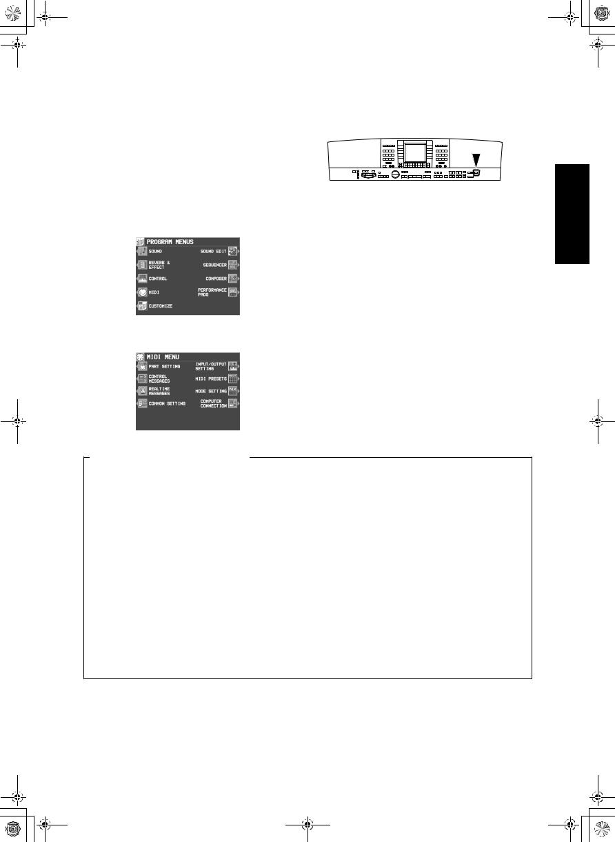
Outline of MIDI functions
1.Press the PROGRAM MENUS button to turn it on.
• The display looks similar to the following.
2. Select MIDI.
• The display looks similar to the following.
Summary of the MIDI menu items
3.Select a function.
4.Follow the procedure to adjust the settings.
•While you are adjusting the settings, when the TEMPO/PROGRAM indicator is lit, it indicates that the TEMPO/PROGRAM is available for setting the current function.
5.When you have finished setting the functions, press the PROGRAM MENUS button to turn it off.
PART SETTING (page 180)
Set the MIDI CHANNEL, OCTAVE and LOCAL CONTROL settings for each part.
CONTROL MESSAGES (page 181)
Enable or disable the exchange of various CONTROL data.
REALTIME MESSAGES (page 181)
Enable or disable the exchange of REALTIME COMMANDS, and select the CLOCK mode.
COMMON SETTING (page 182)
Set the functions which are common to all parts.
INPUT/OUTPUT SETTING (page 183) Settings which determine how various performance data is treated during data transmission and reception.
MIDI PRESETS (page 184)
Establish the optimum settings depending on how this instrument is connected to other equipment.
•You can save the settings you specify yourself.
MODE SETTING (page 183)
NX SOUND and GM LEVEL 2 ON setting
COMPUTER CONNECTION (page 185) Mode settings related to the flow of MIDI signals when this instrument is connected to a personal computer.
MIDI
179
QQTG0692
 18_Part XIII.fm 180
MIDI
Part XIII |
MIDI |
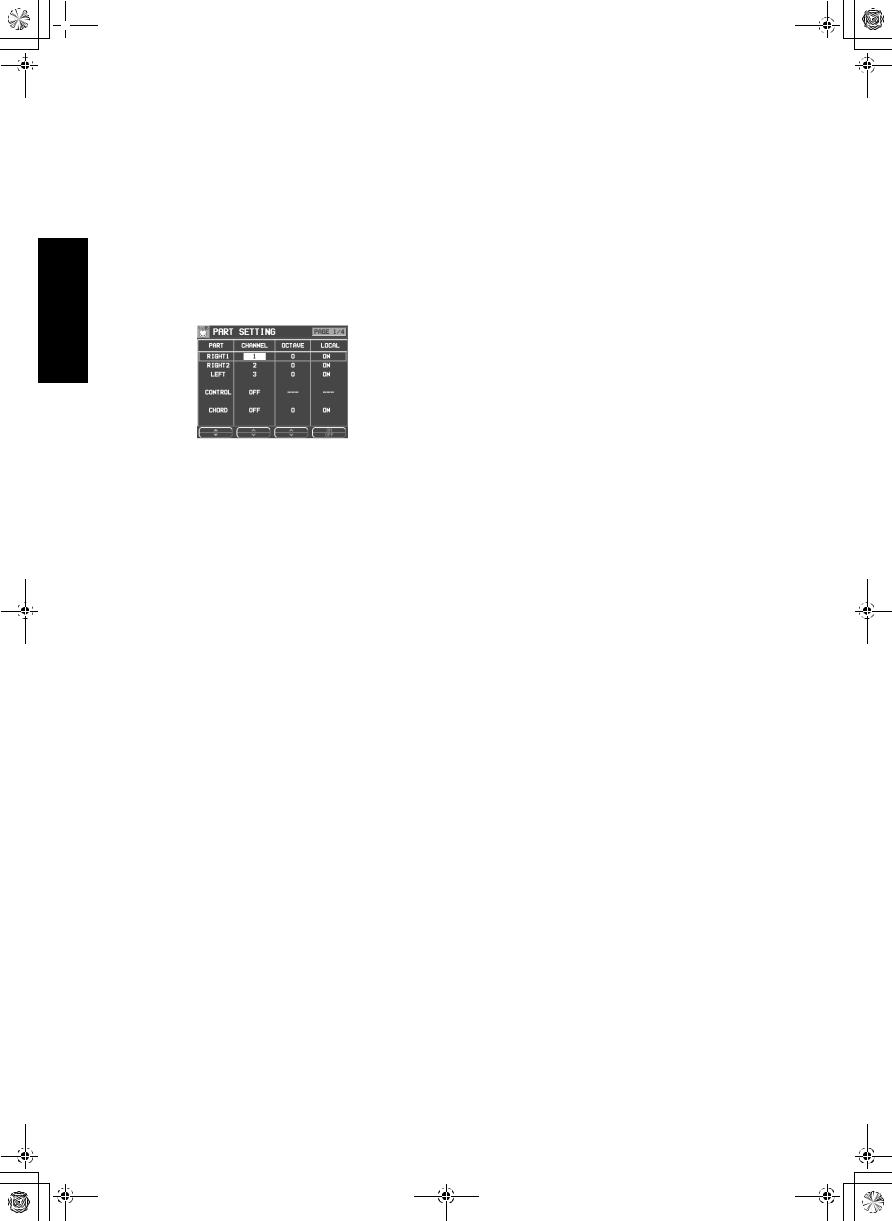
Part Setting
Follow this procedure to set the functions which can be set for each part: MIDI CHANNELs, the OCTAVE data to NOTE data during transmission, and LOCAL CONTROL (whether or not the sound generator of this instrument is active during transmission).
1. On the MIDI MENU display, select PART SETTING.
• The display looks similar to the following.
2. Use the PART ▲ and ▼ buttons to select a part.
•The list of parts covers 4 pages. Use the
OTHER PARTS/TR button or PAGE button to view different parts.
3. Use the CHANNEL and buttons to select a MIDI CHANNEL for the part (OFF, 1 to 16).
•A part which has been set to OFF cannot be used to transmit or receive MIDI data.
•The initialized settings are as follows:
RIGHT 1 |
1 |
RIGHT 2 |
2 |
LEFT |
3 |
PART 1 |
OFF |
PART 2 |
OFF |
PART 3 |
OFF |
PART 4 |
4 |
PART 5 |
5 |
PART 6 |
6 |
PART 7 |
7 |
PART 8 |
8 |
PART 9 |
9 |
PART 10 |
10 |
PART 11 |
11 |
PART 12 |
12 |
PART 13 |
13 |
PART 14 |
14 |
PART 15 |
15 |
PART 16 |
16 |
CONTROL |
OFF |
ACCOMP 1 – 5 |
OFF |
BASS |
OFF |
DRUMS 1 – 2 |
OFF |
CHORD |
OFF |
4. Use the OCTAVE and buttons to set the octave shift value (−3 to 3).
•Octave shift is set for transmitted data only; however the transmitted and received octave shifts are linked. For example, if the transmit-
ted octave shift is set to 1, the received octave shift is automatically set to −1.
5. Use the LOCAL and buttons to enable or disable this instrument’s sound generator.
•When set to ON, the performance from this instrument is transmitted as MIDI data and also sounds from this instrument. When set to OFF, the performance from this instrument is transmitted as MIDI data but does not sound from this instrument.
6. Repeat steps 2 to 5 for each part as desired.
180
QQTG0692
 Loading...