


 Loading...
Dell™ PowerConnect™ 6024/6024F Systems
User’s Guide
w w w . d e l l . c o m | s u p p o r t . d e l l . c o m

Notes, Notices, and Cautions
NOTE: A NOTE indicates important information that helps you make better use of your computer.
NOTICE: A NOTICE indicates either potential damage to hardware or loss of data and tells you how to avoid the problem.
 CAUTION: A CAUTION indicates a potential for property damage, personal injury, or death.
____________________
Information in this document is subject to change without notice. © 2005 Dell Inc. All rights reserved.
Reproduction in any manner whatsoever without the written permission of Dell Inc. is strictly forbidden.
Trademarks used in this text: Dell, Dell OpenManage, the DELL logo, Inspiron, Dell Precision, Dimension, OptiPlex, PowerConnect, PowerApp, PowerVault, Axim, DellNet, and Latitude are trademarks of Dell Inc. Microsoft and Windows are registered trademarks of Microsoft Corporation.
Other trademarks and trade names may be used in this document to refer to either the entities claiming the marks and names or their products. Dell Inc. disclaims any proprietary interest in trademarks and trade names other than its own.
April 2005 Rev A04

Contents
1 Introduction |
|
PowerConnect 6024 . . . . . . . . . . . . . . . . . . . . . . . . . . . . |
23 |
PowerConnect 6024F. . . . . . . . . . . . . . . . . . . . . . . . . . . . |
24 |
CLI Documentation. . . . . . . . . . . . . . . . . . . . . . . . . . . . . |
24 |
Features. . . . . . . . . . . . . . . . . . . . . . . . . . . . . . . . . . |
24 |
Port Based Features. . . . . . . . . . . . . . . . . . . . . . . . . . |
24 |
MAC Address Supported Features . . . . . . . . . . . . . . . . . . . |
26 |
Layer 2 Features . . . . . . . . . . . . . . . . . . . . . . . . . . . |
26 |
VLAN Supported Features . . . . . . . . . . . . . . . . . . . . . . . |
27 |
Spanning Tree Protocol Features. . . . . . . . . . . . . . . . . . . . |
28 |
Link Aggregation . . . . . . . . . . . . . . . . . . . . . . . . . . . |
29 |
Routing Features . . . . . . . . . . . . . . . . . . . . . . . . . . . |
29 |
Layer 3 Features . . . . . . . . . . . . . . . . . . . . . . . . . . . |
31 |
Quality of Service Features . . . . . . . . . . . . . . . . . . . . . . |
31 |
Device Management Features . . . . . . . . . . . . . . . . . . . . . |
32 |
Security Features . . . . . . . . . . . . . . . . . . . . . . . . . . . |
34 |
2 Hardware Description
Ports Description . . . . . . . . . . . . . . . . . . . . . . . . . . . . . |
37 |
PowerConnect 6024 . . . . . . . . . . . . . . . . . . . . . . . . . . |
37 |
PowerConnect 6024F . . . . . . . . . . . . . . . . . . . . . . . . . |
38 |
Out-of-Band Management Port . . . . . . . . . . . . . . . . . . . . |
38 |
Console (RS-232) Port . . . . . . . . . . . . . . . . . . . . . . . . . |
38 |
Hardware Components. . . . . . . . . . . . . . . . . . . . . . . . . . . |
39 |
Physical Dimensions . . . . . . . . . . . . . . . . . . . . . . . . . |
39 |
Power Supplies . . . . . . . . . . . . . . . . . . . . . . . . . . . . |
39 |
Reset Button . . . . . . . . . . . . . . . . . . . . . . . . . . . . . |
40 |
Ventilation System. . . . . . . . . . . . . . . . . . . . . . . . . . . |
40 |
LED Definitions . . . . . . . . . . . . . . . . . . . . . . . . . . . . . . |
40 |
SFP Port LEDs. . . . . . . . . . . . . . . . . . . . . . . . . . . . . |
41 |
System LEDs . . . . . . . . . . . . . . . . . . . . . . . . . . . . . |
42 |
Contents 3

3 Cable, Port, and Pinout Information
Pin Connections for the 10/100/1000 Ethernet Interface . . . . . . . . . . . |
45 |
Pin Connections for SFP Interfaces . . . . . . . . . . . . . . . . . . . . . |
46 |
Serial Cable Connection . . . . . . . . . . . . . . . . . . . . . . . . . . |
47 |
Connecting the Switch to a Terminal . . . . . . . . . . . . . . . . . . |
48 |
AC Power Connection . . . . . . . . . . . . . . . . . . . . . . . . . . . |
49 |
4 Using Dell OpenManage Switch Administrator
Starting the Application . . . . . . . . . . . . . . . . . . . . . . . . . . |
51 |
Understanding the Interface . . . . . . . . . . . . . . . . . . . . . . . . |
51 |
Using the Switch Administrator Buttons . . . . . . . . . . . . . . . . . . |
53 |
Information Buttons . . . . . . . . . . . . . . . . . . . . . . . . . . |
53 |
Device Management Buttons . . . . . . . . . . . . . . . . . . . . . |
54 |
Defining Fields . . . . . . . . . . . . . . . . . . . . . . . . . . . . . . |
54 |
Accessing the Switch Through the CLI . . . . . . . . . . . . . . . . . . . |
55 |
Console Connection . . . . . . . . . . . . . . . . . . . . . . . . . . |
55 |
Telnet Connection . . . . . . . . . . . . . . . . . . . . . . . . . . . |
55 |
Using the CLI . . . . . . . . . . . . . . . . . . . . . . . . . . . . . . . |
56 |
Command Mode Overview. . . . . . . . . . . . . . . . . . . . . . . |
56 |
User EXEC Mode . . . . . . . . . . . . . . . . . . . . . . . . . . . |
56 |
Privileged EXEC Mode. . . . . . . . . . . . . . . . . . . . . . . . . |
56 |
Global Configuration Mode . . . . . . . . . . . . . . . . . . . . . . |
57 |
Interface Configuration Mode . . . . . . . . . . . . . . . . . . . . . |
58 |
CLI Examples . . . . . . . . . . . . . . . . . . . . . . . . . . . . . |
58 |
5 |
Configuring the Switch |
|
|
General Configuration Information . . . . . . . . . . . . . . . . . . . . . |
61 |
|
Auto-Negotiation . . . . . . . . . . . . . . . . . . . . . . . . . . . |
61 |
|
Switching Port Default Settings . . . . . . . . . . . . . . . . . . . . |
61 |
|
Terminal Connection Configuration . . . . . . . . . . . . . . . . . . . |
62 |
|
Baud Rate . . . . . . . . . . . . . . . . . . . . . . . . . . . . . . |
62 |
|
Other Configuration Requirements . . . . . . . . . . . . . . . . . . . . . |
63 |
4 Contents

Booting the Switch . . . . . . . . . . . . . . . . . . . . . . . . . . . . |
63 |
Configuration Overview . . . . . . . . . . . . . . . . . . . . . . . . . . |
66 |
Initial Configuration . . . . . . . . . . . . . . . . . . . . . . . . . . . . |
66 |
Advanced Configuration . . . . . . . . . . . . . . . . . . . . . . . . . . |
70 |
Retrieving an IP Address From a DHCP Server . . . . . . . . . . . . . |
70 |
Receiving an IP Address From a BOOTP Server . . . . . . . . . . . . . |
71 |
Security Management and Password Configuration. . . . . . . . . . . |
72 |
Configuring Security Passwords . . . . . . . . . . . . . . . . . . . . |
72 |
Software Download and Reboot . . . . . . . . . . . . . . . . . . . . . . |
74 |
Software Download Through XModem . . . . . . . . . . . . . . . . . |
74 |
Software Download Through TFTP Server . . . . . . . . . . . . . . . |
75 |
Boot Image Download. . . . . . . . . . . . . . . . . . . . . . . . . |
77 |
Sample Configuration Process . . . . . . . . . . . . . . . . . . . . . . . |
77 |
Device Setup Requirements . . . . . . . . . . . . . . . . . . . . . . |
78 |
Initial Connection . . . . . . . . . . . . . . . . . . . . . . . . . . . |
78 |
Device Default Settings. . . . . . . . . . . . . . . . . . . |
82 |
Enabling Remote Management. . . . . . . . . . . . . . . . . . . . . |
82 |
Setting the Management Station IP Address . . . . . . . . . . . . . . |
85 |
Enabling Telnet Access . . . . . . . . . . . . . . . . . . . . . . . . |
87 |
Enabling Web Access (HTTP Server) . . . . . . . . . . . . . . . . . . |
89 |
Configuring Secure Management Access (HTTPS) . . . . . . . . . . . |
91 |
Startup Menu Functions . . . . . . . . . . . . . . . . . . . . . . . . . . |
92 |
Download Software . . . . . . . . . . . . . . . . . . . . . . . . . . |
93 |
Erase FLASH File . . . . . . . . . . . . . . . . . . . . . . . . . . . |
93 |
Erase FLASH Sectors . . . . . . . . . . . . . . . . . . . . . . . . . |
94 |
Password Recovery . . . . . . . . . . . . . . . . . . . . . . . . . . |
95 |
Out-of-Band Management Port . . . . . . . . . . . . . . . . . . . . . . . |
95 |
Assigning Dynamic IP Addresses (on an Out-of-Band Port) . . . . . . . |
95 |
Assigning Static IP Addresses (on an Out-of-Band Port). . . . . . . . . |
96 |
Assigning IP Default Gateway . . . . . . . . . . . . . . . . . . . . . |
96 |
Ping via Out-of-Band . . . . . . . . . . . . . . . . . . . . . . . . . |
96 |
Copy Image/Boot . . . . . . . . . . . . . . . . . . . . . . . . . . . |
96 |
IP Default Gateway to Out-of-Band. . . . . . . . . . . . . . . . . . . |
96 |
Additional Information. . . . . . . . . . . . . . . . . . . . . . . . . |
97 |
Contents 5

6 Configuring System Information
Opening the System Page . . . . . . . . . . . . . . . . . . . . . . . . . |
99 |
Defining General Device Information . . . . . . . . . . . . . . . . . . . . |
99 |
Configuring Device Information . . . . . . . . . . . . . . . . . . . . |
99 |
Defining System Time Settings . . . . . . . . . . . . . . . . . . . . |
102 |
The following is an example of CLI commands: . . . . . . . . . . . . |
105 |
Configuring System Health Information . . . . . . . . . . . . . . . . |
105 |
The following is an example of the CLI commands: . . . . . . . . . . |
107 |
Version Information . . . . . . . . . . . . . . . . . . . . . . . . . |
108 |
Resetting the Device . . . . . . . . . . . . . . . . . . . . . . . . |
109 |
Configuring SNTP Settings . . . . . . . . . . . . . . . . . . . . . . . . |
110 |
Defining SNTP Global Parameters . . . . . . . . . . . . . . . . . . |
111 |
Defining SNTP Authentication Methods . . . . . . . . . . . . . . . |
114 |
Defining SNTP Servers . . . . . . . . . . . . . . . . . . . . . . . |
116 |
Defining SNTP Interfaces . . . . . . . . . . . . . . . . . . . . . . |
120 |
Configuring Out-of-Band (OOB) Management Ports . . . . . . . . . . . . |
122 |
Configuring Out-of-Band Remote Log Servers . . . . . . . . . . . . |
122 |
Defining Out-of-Band Default Gateways . . . . . . . . . . . . . . . |
124 |
Defining Out-of-Band IP Interface Parameters . . . . . . . . . . . . |
125 |
Configuring Out-of-Band TACACS+ Servers. . . . . . . . . . . . . . |
127 |
Configuring Out-of-Band RADIUS Servers . . . . . . . . . . . . . . |
132 |
Managing Logs . . . . . . . . . . . . . . . . . . . . . . . . . . . . . |
135 |
Global Log Parameters . . . . . . . . . . . . . . . . . . . . . . . |
135 |
RAM Log Table . . . . . . . . . . . . . . . . . . . . . . . . . . . |
138 |
Log File Table . . . . . . . . . . . . . . . . . . . . . . . . . . . . |
139 |
Remote Log Server . . . . . . . . . . . . . . . . . . . . . . . . . |
141 |
Defining IP Addressing. . . . . . . . . . . . . . . . . . . . . . . . . . |
143 |
Defining IP Interfaces . . . . . . . . . . . . . . . . . . . . . . . . |
144 |
Defining DHCP IP Interface Parameters . . . . . . . . . . . . . . . |
147 |
Configuring Domain Name Systems . . . . . . . . . . . . . . . . . |
148 |
Defining Default Domains . . . . . . . . . . . . . . . . . . . . . . |
151 |
Mapping the Domain Host . . . . . . . . . . . . . . . . . . . . . . |
153 |
Enabling ARP Proxy . . . . . . . . . . . . . . . . . . . . . . . . . |
156 |
Defining ARP Settings . . . . . . . . . . . . . . . . . . . . . . . . |
157 |
Defining DHCP Relay Parameters . . . . . . . . . . . . . . . . . . |
160 |
Configuring UDP Relay . . . . . . . . . . . . . . . . . . . . . . . |
163 |
6 Contents

Running Cable Diagnostics. . . . . . . . . . . . . . . . . . . . . . . . |
166 |
Viewing Copper Cable Diagnostics . . . . . . . . . . . . . . . . . . |
166 |
Viewing Optical Transceiver Diagnostics . . . . . . . . . . . . . . . |
168 |
Managing Device Security . . . . . . . . . . . . . . . . . . . . . . . . |
170 |
Defining Access Profiles . . . . . . . . . . . . . . . . . . . . . . |
170 |
Defining Authentication Profiles . . . . . . . . . . . . . . . . . . . |
175 |
Selecting Authentication Profiles . . . . . . . . . . . . . . . . . . |
177 |
Managing Passwords . . . . . . . . . . . . . . . . . . . . . . . . |
182 |
Defining the Local User Databases. . . . . . . . . . . . . . . . . . |
184 |
Defining Line Passwords . . . . . . . . . . . . . . . . . . . . . . |
186 |
Defining Enable Password . . . . . . . . . . . . . . . . . . . . . . |
188 |
Configuring TACACS+ Settings . . . . . . . . . . . . . . . . . . . . |
189 |
Configuring RADIUS Settings . . . . . . . . . . . . . . . . . . . . |
194 |
Defining SNMP Parameters . . . . . . . . . . . . . . . . . . . . . . . |
197 |
SNMP v1 and v2 . . . . . . . . . . . . . . . . . . . . . . . . . . |
197 |
SNMP v3 . . . . . . . . . . . . . . . . . . . . . . . . . . . . . . |
197 |
Defining SNMP Global Parameters. . . . . . . . . . . . . . . . . . |
198 |
Defining SNMP Views . . . . . . . . . . . . . . . . . . . . . . . . |
201 |
Defining SNMP Access Control . . . . . . . . . . . . . . . . . . . |
204 |
Assigning SNMP User Security . . . . . . . . . . . . . . . . . . . |
207 |
Defining Communities . . . . . . . . . . . . . . . . . . . . . . . . |
211 |
Defining SNMP Notification Filters . . . . . . . . . . . . . . . . . . |
214 |
Defining SNMP Notification Recipients. . . . . . . . . . . . . . . . |
217 |
Managing Files . . . . . . . . . . . . . . . . . . . . . . . . . . . . . |
223 |
Management File Overview . . . . . . . . . . . . . . . . . . . . . |
223 |
Downloading Files. . . . . . . . . . . . . . . . . . . . . . . . . . |
224 |
Copying Files . . . . . . . . . . . . . . . . . . . . . . . . . . . . |
228 |
Defining Advanced Settings . . . . . . . . . . . . . . . . . . . . . . . |
230 |
Configuring General Settings . . . . . . . . . . . . . . . . . . . . |
230 |
7 Configuring Switch Information
Configuring Network Security . . . . . . . . . . . . . . . . . . . . . . |
233 |
Port Based Authentication (802.1x) . . . . . . . . . . . . . . . . . . |
233 |
Configuring Port Based Authentication . . . . . . . . . . . . . . . . |
234 |
Configuring Advanced Port Based Authentication. . . . . . . . . . . |
239 |
Authenticating Users . . . . . . . . . . . . . . . . . . . . . . . . |
241 |
Contents 7

Configuring Port Security . . . . . . . . . . . . . . . . . . . . . . |
242 |
Defining IP based ACLs . . . . . . . . . . . . . . . . . . . . . . . |
245 |
Defining MAC based ACLs . . . . . . . . . . . . . . . . . . . . . . |
250 |
Configuring ACL Binding. . . . . . . . . . . . . . . . . . . . . . . |
253 |
Configuring Ports . . . . . . . . . . . . . . . . . . . . . . . . . . . . |
256 |
Defining Port Configuration . . . . . . . . . . . . . . . . . . . . . |
256 |
Defining LAG Configuration . . . . . . . . . . . . . . . . . . . . . |
262 |
Enabling Storm Control . . . . . . . . . . . . . . . . . . . . . . . |
265 |
Defining Port Mirroring Sessions. . . . . . . . . . . . . . . . . . . |
267 |
Configuring Address Tables . . . . . . . . . . . . . . . . . . . . . . . |
269 |
Defining Static Addresses . . . . . . . . . . . . . . . . . . . . . . |
270 |
Viewing Dynamic Addresses. . . . . . . . . . . . . . . . . . . . . |
272 |
Configuring GARP . . . . . . . . . . . . . . . . . . . . . . . . . . . . |
275 |
Defining GARP Timers . . . . . . . . . . . . . . . . . . . . . . . . |
275 |
Configuring the Spanning Tree Protocol . . . . . . . . . . . . . . . . . |
277 |
Defining STP Global Settings. . . . . . . . . . . . . . . . . . . . . |
277 |
Defining STP Port Settings. . . . . . . . . . . . . . . . . . . . . . |
281 |
Defining STP LAG Settings. . . . . . . . . . . . . . . . . . . . . . |
285 |
Defining the Rapid Spanning Tree . . . . . . . . . . . . . . . . . . |
288 |
Defining the Multiple Spanning Tree . . . . . . . . . . . . . . . . . |
289 |
Defining MSTP Interface Settings . . . . . . . . . . . . . . . . . . |
293 |
Configuring VLANs. . . . . . . . . . . . . . . . . . . . . . . . . . . . |
296 |
Defining VLAN Membership . . . . . . . . . . . . . . . . . . . . . |
296 |
Defining VLAN Port Settings . . . . . . . . . . . . . . . . . . . . . |
300 |
Defining VLAN LAG Settings . . . . . . . . . . . . . . . . . . . . . |
303 |
Defining VLAN Protocol Groups . . . . . . . . . . . . . . . . . . . |
305 |
Adding Protocol Ports . . . . . . . . . . . . . . . . . . . . . . . . |
306 |
Configuring GVRP . . . . . . . . . . . . . . . . . . . . . . . . . . |
308 |
Aggregating Ports . . . . . . . . . . . . . . . . . . . . . . . . . . . . |
312 |
Defining LACP Parameters. . . . . . . . . . . . . . . . . . . . . . |
313 |
Defining LAG Membership . . . . . . . . . . . . . . . . . . . . . . |
315 |
Multicast Forwarding Support . . . . . . . . . . . . . . . . . . . . . . |
317 |
Defining Multicast Global Parameters . . . . . . . . . . . . . . . . |
317 |
Adding Bridge Multicast Address Members . . . . . . . . . . . . . |
319 |
Assigning Multicast Forward All Parameters . . . . . . . . . . . . . |
323 |
IGMP Snooping . . . . . . . . . . . . . . . . . . . . . . . . . . . |
326 |
8 Contents

8 Configuring Routing |
|
Routing Overview . . . . . . . . . . . . . . . . . . . . . . . . . . . . |
331 |
Configuring Global IP Routing . . . . . . . . . . . . . . . . . . . . . . |
331 |
Configuring the IP Forwarding Table . . . . . . . . . . . . . . . . . |
331 |
Configuring IP Static Routes . . . . . . . . . . . . . . . . . . . . . |
334 |
Configuring VRRP . . . . . . . . . . . . . . . . . . . . . . . . . . |
336 |
Configuring MD5 Routing Authentication . . . . . . . . . . . . . . . |
340 |
Configuring MD5 Key Chain Settings . . . . . . . . . . . . . . . . . |
343 |
Configuring RIP . . . . . . . . . . . . . . . . . . . . . . . . . . . . . |
346 |
Defining RIP Global Parameters . . . . . . . . . . . . . . . . . . . |
346 |
Defining RIP Interface Parameters . . . . . . . . . . . . . . . . . . |
348 |
Configuring OSPF Parameters and Filters . . . . . . . . . . . . . . . . . |
352 |
Configuring OSPF Parameters . . . . . . . . . . . . . . . . . . . . |
352 |
Configuring OSPF Areas . . . . . . . . . . . . . . . . . . . . . . . |
354 |
Configuring the OSPF Virtual Links . . . . . . . . . . . . . . . . . . |
357 |
Configuring OSPF Interface Parameters . . . . . . . . . . . . . . . |
360 |
Viewing the Link State Table . . . . . . . . . . . . . . . . . . . . . |
365 |
Viewing the External Link State Table. . . . . . . . . . . . . . . . . |
366 |
Viewing the OSPF Neighbor Table . . . . . . . . . . . . . . . . . . |
368 |
Configuring IP Multicast Routing . . . . . . . . . . . . . . . . . . . . . |
370 |
Defining IPM Global Parameters . . . . . . . . . . . . . . . . . . . |
370 |
Defining IGMP Interface Parameters . . . . . . . . . . . . . . . . . |
371 |
Defining IGMP Static Interface Groups . . . . . . . . . . . . . . . . |
374 |
Viewing the IGMP Dynamic Group Table . . . . . . . . . . . . . . . |
375 |
Configuring DVMRP Interfaces . . . . . . . . . . . . . . . . . . . |
377 |
DVMRP Prune Table. . . . . . . . . . . . . . . . . . . . . . . . . |
380 |
DVMRP Route Table . . . . . . . . . . . . . . . . . . . . . . . . . |
381 |
DVMRP Next Hop Table . . . . . . . . . . . . . . . . . . . . . . . |
382 |
DVMRP Neighbor Table . . . . . . . . . . . . . . . . . . . . . . . |
384 |
Viewing the IP Multicast Routing Table . . . . . . . . . . . . . . . . |
385 |
Viewing the IP Multicast Next Hop Table . . . . . . . . . . . . . . . |
387 |
9 Viewing Statistics
Viewing Tables . . . . . . . . . . . . . . . . . . . . . . . . . . . . . |
389 |
Viewing Utilization Summary. . . . . . . . . . . . . . . . . . . . . |
389 |
Viewing Counter Summary. . . . . . . . . . . . . . . . . . . . . . |
390 |
Contents 9

Viewing Interface Statistics . . . . . . . . . . . . . . . . . . . . . |
391 |
Viewing Etherlike Statistics . . . . . . . . . . . . . . . . . . . . . |
395 |
Viewing GVRP Statistics . . . . . . . . . . . . . . . . . . . . . . . |
397 |
Viewing EAP Statistics . . . . . . . . . . . . . . . . . . . . . . . |
400 |
Viewing RMON Statistics . . . . . . . . . . . . . . . . . . . . . . . . |
402 |
Viewing RMON Statistics Group . . . . . . . . . . . . . . . . . . . |
402 |
Viewing RMON History Control Statistics . . . . . . . . . . . . . . . |
405 |
Viewing the RMON History Table. . . . . . . . . . . . . . . . . . . |
407 |
Defining Device RMON Events . . . . . . . . . . . . . . . . . . . . |
409 |
Viewing the RMON Events Log . . . . . . . . . . . . . . . . . . . . |
412 |
Defining RMON Device Alarms. . . . . . . . . . . . . . . . . . . . |
413 |
Viewing Charts . . . . . . . . . . . . . . . . . . . . . . . . . . . . . |
416 |
Viewing Port Statistics . . . . . . . . . . . . . . . . . . . . . . . |
416 |
Viewing LAG Statistics . . . . . . . . . . . . . . . . . . . . . . . |
419 |
10 Configuring Quality of Service
Quality of Service Overview . . . . . . . . . . . . . . . . . . . . . . . |
421 |
QoS Modes . . . . . . . . . . . . . . . . . . . . . . . . . . . . . |
424 |
Configuring QoS Global Parameters . . . . . . . . . . . . . . . . . . . |
426 |
Defining QoS Settings . . . . . . . . . . . . . . . . . . . . . . . . |
426 |
Defining Bandwidth Settings. . . . . . . . . . . . . . . . . . . . . |
430 |
Defining Global Queue Settings . . . . . . . . . . . . . . . . . . . |
435 |
Defining CoS to Queue Mapping . . . . . . . . . . . . . . . . . . . |
437 |
Defining DSCP to Queue Mapping . . . . . . . . . . . . . . . . . . |
440 |
Defining QoS TCP to Queue Mapping. . . . . . . . . . . . . . . . . |
441 |
Defining QoS UDP to Queue Mapping . . . . . . . . . . . . . . . . |
443 |
Configuring Basic QoS Mode. . . . . . . . . . . . . . . . . . . . . . . |
445 |
Defining Basic QoS Settings . . . . . . . . . . . . . . . . . . . . . |
446 |
Defining QoS DSCP Rewriting Settings . . . . . . . . . . . . . . . . |
448 |
Configuring Advanced QoS Mode. . . . . . . . . . . . . . . . . . . . . |
449 |
Defining QoS DSCP Mapping Settings . . . . . . . . . . . . . . . . |
449 |
Defining QoS Tail Drop Settings . . . . . . . . . . . . . . . . . . . |
451 |
Defining QoS Class Maps . . . . . . . . . . . . . . . . . . . . . . |
452 |
Defining QoS Aggregate Policers . . . . . . . . . . . . . . . . . . |
455 |
Defining Policies . . . . . . . . . . . . . . . . . . . . . . . . . . |
457 |
Applying Policies to Interfaces. . . . . . . . . . . . . . . . . . . . |
461 |
10 Contents
11 Getting Help
Technical Assistance . . . . . . . . . . . . . . . . . . . . . . . . . . |
465 |
Online Services . . . . . . . . . . . . . . . . . . . . . . . . . . . |
465 |
AutoTech Service . . . . . . . . . . . . . . . . . . . . . . . . . . |
466 |
Automated Order-Status Service. . . . . . . . . . . . . . . . . . . |
466 |
Technical Support Service. . . . . . . . . . . . . . . . . . . . . . |
466 |
Dell Enterprise Training and Certification . . . . . . . . . . . . . . . . . |
467 |
Problems With Your Order . . . . . . . . . . . . . . . . . . . . . . . . |
467 |
Product Information . . . . . . . . . . . . . . . . . . . . . . . . . . . |
467 |
Returning Items for Warranty Repair or Credit. . . . . . . . . . . . . . . |
467 |
Before You Call . . . . . . . . . . . . . . . . . . . . . . . . . . . . . |
468 |
Contacting Dell . . . . . . . . . . . . . . . . . . . . . . . . . . . . . |
468 |
Contents 11

12 Contents

Introduction
NOTICE: Before proceeding, read the release notes for this product. You can download the release notes from support.dell.com.
The Dell™ PowerConnect™ 6024/6024F is a standalone Layer 3 switch that extends the Dell PowerConnect LAN switching product range. The switch includes the following features:
•1U form factor, rack-mountable chassis design
•Out-of-band management port for RJ-45 and RS-232 connections.
•Support for all data-communication requirements for a multi-layer switch, including a full suite of Layer 2, Layer 3+, security, and management features.
•High availability with hot swappable power supplies and cooling fans
PowerConnect 6024
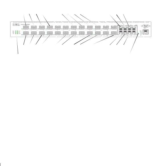
The PowerConnect 6024 provides 24 10/100/1000 Base-T RJ-45 ports with eight SFP combo ports that have an auto-sensing mode for speed, flow control, and duplex mode. SFP transceivers are sold separately.
Figure 1-1. PowerConnect 6024
|
|
|
|
|
|
|
|
|
|
|
|
|
|
|
Console |
|
|
|
|
|
|
|
|
|
|
|
|
|
|
|
(RS-232) |
|
|
|
|
|
Base-TPorts |
|
|
|
|
|
SFP Ports |
|
|||
1 |
3 |
5 |
7 |
9 |
11 |
13 |
15 |
17 |
19 |
21 |
23 |
17 |
19 |
21 |
23 |
2 |
4 |
6 |
8 |
10 |
12 |
14 |
16 |
18 |
20 |
22 |
24 |
18 |
20 |
22 |
24 |
|
|
|
|
|
Base-TPorts |
|
|
|
|
|
SFP Ports |
|
|||
System |
|
|
|
|
|
|
|
|
|
|
|
|
Reset Button |
||
LEDS |
|
|
|
|
|
|
|
|
|
|
|
|
|||
|
|
|
|
|
|
|
|
|
|
|
|
|
Out of Band |
||
|
|
|
|
|
|
|
|
|
|
|
|
|
|
|
|
Introduction 23
w w w . d e l l . c o m | s u p p o r t . d e l l . c o m
PowerConnect 6024F
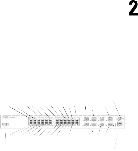
PowerConnect 6024F provides 24 SFP ports with 8 10/100/1000 Base-T RJ-45 combo ports that have an auto-sensing mode for speed, flow control, and duplex mode. SFP transceivers are sold separately.
Figure 1-2. PowerConnect 6024F
CLI Documentation
|
|
|
|
|
|
|
|
|
|
|
|
|
|
|
Console |
|
|
|
|
|
|
|
|
|
|
|
|
|
|
|
(RS-232) |
|
|
|
|
|
SFP Ports |
|
|
|
|
Base-T Ports |
|||||
1 |
3 |
5 |
7 |
9 |
11 |
13 |
15 |
17 |
19 |
21 |
23 |
17 |
19 |
21 |
23 |
2 |
4 |
6 |
8 |
10 |
12 |
14 |
16 |
18 |
20 |
22 |
24 |
18 |
20 |
22 |
24 |
|
|
|
|
|
SFP Ports |
|
|
|
|
Base-T Ports |
|||||
System LEDs |
|
|
|
|
|
|
|
|
|
|
Reset Button |
||||
Out of Band
The CLI Reference Guide provides information about the CLI commands used to configure the switch. The document provides CLI descriptions, syntax, and default values.
Features
This section describes the switch’s user-configurable features. For a list of all features, refer to the software version release notes.
Port Based Features
Virtual Cable Testing (VCT)
VCT detects and reports potential copper link cabling issues, such as cable opens or cable shorts.
Jumbo Frames Support
Jumbo frames enables transporting identical data in fewer frames to ensure less overhead, lower processing time, and fewer interrupts.
MDI/MDIX Support
Your switch supports auto-detection between crossed and straight-through cables.
24 Introduction

Standard wiring for end stations is Media-Dependent Interface (MDI) and the standard wiring for hubs and switches is known as Media-Dependent Interface with Crossover (MDIX).
For information about configuring MDI/MDI for ports or LAGs, see "Defining Port Configuration" or "Defining LAG Configuration."
Hardware Watchdog Support
The switch uses Hardware Watchdog to detect issues and take corrective action when the software stops responding.
Auto Negotiation
Auto negotiation allows the device to advertise modes of operation. The auto negotiation function provides the means to exchange information between two devices that share a point-to-point link segment, and to automatically configure both devices to take maximum advantage of their transmission capabilities.
The PowerConnect 6024/6024F enhances auto negotiation by providing port advertisement. Port advertisement allows the system administrator to configure the port speeds advertised.
For information about auto negotiation, see "Defining Port Configuration" or "Defining LAG Configuration."
Flow Control Support (IEEE 802.3X)
Flow control enables lower speed devices to communicate with higher speed devices by requesting that the higher speed device refrains from sending packets. Transmissions are temporarily halted to prevent buffer overflows.
For information about configuring flow control for ports or LAGs, see "Defining Port Configuration" or "Defining LAG Configuration."
Head of Line Blocking Prevention
Head of Line (HOL) blocking prevents traffic delays and frame loss caused by traffic competing for the same egress port resources. HOL blocking queues packets, and the packets at the head of the queue are forwarded before packets at the end of the queue.
Back Pressure Support
On half-duplex links, a receiver may prevent buffer overflows by occupying the link so that it is unavailable for additional traffic.
For information about configuring Back Pressure for ports or LAGs, see "Defining Port Configuration" or "Defining LAG Configuration."
Introduction 25

w w w . d e l l . c o m | s u p p o r t . d e l l . c o m
MAC Address Supported Features
MAC Address Support
The switch supports up to 16K MAC addresses and reserves specific MAC addresses for system use.
Self-Learning MAC Addresses
The switch enables MAC addresses to be automatically learned from incoming packets.
Automatic Aging for MAC Addresses
MAC addresses that have not seen any traffic for a given period are aged out, which prevents the Bridging Table from overflowing.
For information about configuring the MAC Address age-out period, see "Viewing Dynamic Addresses."
Static MAC Entries
User-defined MAC entries are stored in the Bridging Table with the self-learned addresses.
For information about configuring the static MAC addresses, see "Defining Static Addresses."
VLAN-Aware MAC-based Switching
Packets arriving from an unknown source address are sent to the CPU and added to the Hardware Table. Future Packets addressed to or from this address are more efficiently forwarded.
MAC Multicast Support
Multicast service is a limited broadcast service that allows one-to-many and many-to-many connections. In Layer 2 multicast services, a single frame addressed to a specific multicast address is received, and copies of the frame to be transmitted on each relevant port are created.
For information about configuring MAC Multicast Support, see "Multicast Forwarding Support."
Layer 2 Features
IGMP Snooping
IGMP Snooping examines the contents of IGMP frames when they are forwarded by the switch from stations to an upstream multicast router. Snooping enables the switch to identify stations interested in multicast sessions and which multicast routers are sending multicast frames.
For information about configuring IGMP Snooping, see "IGMP Snooping."
Port Mirroring
Port mirroring monitors and mirrors network traffic by forwarding copies of incoming and outgoing packets from one port to a monitoring port.
26 Introduction

For information about configuring port mirroring, see "Defining Port Mirroring Sessions."
Broadcast Storm Control
When Layer 2 frames are forwarded, broadcast and multicast frames are flooded to all ports on the relevant VLAN. The flooding occupies bandwidth, and loads all nodes connected on all ports. Storm control limits the amount of multicast and broadcast frames accepted and forwarded by the switch.
For information about configuring storm control, see "Enabling Storm Control."
VLAN Supported Features
VLAN Support
VLANs are collections of switching ports that comprise a single broadcast domain. Packets are classified as belonging to a VLAN based on either the VLAN tag or a combination of the ingress port and packet contents. Packets sharing common attributes can be groups in the same VLAN.
For information about configuring VLANs, see "Configuring VLANs."
Port-Based VLANs
Port-based VLANs classify incoming packets to VLANs based on their ingress port.
For information about configuring VLANs, see "Configuring VLANs."
IEEE802.1V Protocol Based VLANs
VLAN classification rules are defined on data-link layer (Layer 2) protocol identification. Protocolbased VLANs are used for isolating Layer 2 traffic for differing Layer 3 protocols.
For information about defining Protocol Based VLANs, see "Defining VLAN Protocol Groups."
Full 802.1Q VLAN Tagging Compliance
IEEE 802.1Q defines an architecture for virtual bridged LANs, the services provided in VLANs, and the protocols and algorithms involved in the provision of these services.
This standard requires an ability to mark frames with a desired Class of Service (CoS) tag value (0-7).
GVRP Support
GARP VLAN Registration Protocol (GVRP) provides IEEE 802.1Q-compliant VLAN pruning and dynamic VLAN creation on 802.1Q trunk ports. When GVRP is enabled, the switch registers and propagates VLAN membership on all ports that are part of the active underlying Spanning Tree protocol topology.
For information about configuring GVRP, see "Configuring GVRP. "
Introduction 27

w w w . d e l l . c o m | s u p p o r t . d e l l . c o m
Private VLAN Edge
Private VLAN Edge (PVE) ports are a Layer 2 security feature that provides port-based security between adjacent ports within a VLAN. It is an extension of the common VLAN. Traffic from protected ports is sent only to the uplink ports and cannot be sent to other ports within the VLAN.
For information about configuring PVE ports, see "Configuring Ports".
Spanning Tree Protocol Features
Spanning Tree Protocol (STP) per Device
802.1d STP is a standard requirement of Layer 2 switches that allows bridges to automatically prevent and resolve L2 forwarding loops. Switches exchange configuration messages, using specifically formatted frames, and selectively enable and disable forwarding on ports.
For information about configuring STP, see "Configuring the Spanning Tree Protocol."
Fast Link
STP can take as long as 30-60 seconds to converge as it detects possible loops and allows time for status changes to propagate and for relevant devices to respond. This duration is considered too long for many applications. Fast Link bypasses this delay without requiring multiple data paths for network resiliency.
For information about enabling Fast Link for ports and LAGs, see "Defining Port Configuration" or "Defining LAG Configuration."
IEEE 802.1W Rapid Spanning Tree
Rapid Spanning Tree Protocol (RSTP) detects uses network topologies to enable faster convergence, without creating forwarding loops.
For information about enabling RSTP, see "Defining the Rapid Spanning Tree."
Multiple Spanning Tree
Multiple Spanning Tree (MSTP) operation maps VLANs into ST instances. MSTP provides a differing load balancing scenario. Packets assigned to various VLANs are transmitted along different paths within MSTP Regions (MST Regions). Regions are one or more interconnected MSTP bridges with identical MSTP settings. The standard lets administrators assign VLAN traffic to unique paths.
For more information about MSTP, see "Defining the Multiple Spanning Tree".
28 Introduction

Link Aggregation
Link Aggregation
Up to seven ports can combine to form a single Link Aggregated Group (LAG). This enables fault tolerance protection from physical link disruption, higher bandwidth connections and improved bandwidth granularity.
A LAG is composed of ports of the same speed, set to full-duplex operation.
For information about configuring LAGs, see "Defining LAG Configuration."
Link Aggregation and LACP
LACP uses peer exchanges across links to determine, on an ongoing basis, the aggregation capability of various links, and continuously provides the maximum level of aggregation capability achievable between a given pair of systems. LACP automatically determines, configures, binds, and monitors the binding of ports to aggregators within the system.
For information about LACP, see "Defining LACP Parameters."
Routing Features
IP Routing
IP routing forwards to a next-hop device any packets that are addressed to the system MAC addresses but not to a system IP address.
For information about configuring IP routing, see "Configuring Global IP Routing."
RIP Versions 1 and 2
Routing Information Protocol (RIP) is a distance-vector routing protocol. RIP selects routes based on the hop count to the destination. RIP 2 enhances the efficiency, usability, and authentication methods of the RIP protocol.
For information about configuring RIP, see "Configuring RIP."
OSPF Version 2
Open Shortest Path First (OSPF) is an internal gateway routing protocol. In networks with a large number of inter-connected routers, OSPF is more efficient than RIP because OSPF uses less link bandwidth and converges more quickly.
For information about configuring OSPF, see "Configuring OSPF Parameters and Filters."
Introduction 29

w w w . d e l l . c o m | s u p p o r t . d e l l . c o m
Address Resolution Protocol (ARP)
In IP routing, routers and Layer 3 switches use various routing protocols to discover network topology and define routing tables. ARP automatically determines Device Next-Hop MAC addresses of systems, including directly attached end systems. Users can override and supplement this by defining additional ARP table entries.
For information about configuring ARP, see "Defining ARP Settings."
ICMP Messages
Internet Control Message Protocol (ICMP) messages are used for out-of-band messages related to network operation or malfunction.
IGMPv2
IGMP enables the router to send IGMP queries in the form of L2 broadcasts over each interface. When a multicast packet is sent, and it has a multicast destination MAC address, all hosts on that router interface receive a copy. Hosts listen to all IGMP reports. If interested multicast groups have already been requested by any station on the same interface, the remaining stations do not send duplicate requests.
For information about configuring IGMP, see "Defining IGMP Interface Parameters."
Longest Prefix Match Support
Longest prefix matches are used primarily to determine the best next-hop route for a packet based solely on the destination address contained in the packet header. Because IP addresses are generally assigned in a manner that reflects the topology of the network, the result of a longest prefix match usually reflects the shortest route to the destination.
DVMRP
Distance Vector Multicast Routing Protocol (DVMRP) advertises the shortest-path routes to multicasting source networks with hosts that can transmit multicast IP traffic.
For information about configuring DVMRP, see "Configuring DVMRP Interfaces."
VRRP
Virtual Router Redundancy Protocol (VRRP) eliminates single points of failure in the routing environment. VRRP uses an election protocol that dynamically assigns responsibility for the virtual router to one of the VRRP routers in the LAN.
The election process provides dynamic failover in the forwarding responsibility, if the master is unavailable. Any virtual router IP address can be used as a default first-hop router by end-hosts.
For information about configuring VRRP, see "Configuring VRRP."
30 Introduction
Layer 3 Features
TCP
Transport Control Protocol (TCP) connections are defined between 2 ports by an initial synchronization exchange. TCP ports are identified by an IP address and a 16-bit port number. Octets streams are divided into TCP packets, each carrying a sequence number.
UDP Relay
UDP Relay enables the device to forward specific UDP broadcasts from one interface to another. IP broadcast packets from one interface are not generally forwarded to another interface. However, some applications use UDP broadcast to detect the availability of a service. Other services require UDP broadcast packets to be routed to provide services to clients on another subnet.
BootP and DHCP Clients
DHCP enables additional setup parameters to be received from a network server upon system startup. DHCP service is an on-going process. DHCP is an extension to BootP.
For information about DHCP, see "Defining DHCP IP Interface Parameters."
BootP Relay
BootP enables a device to solicit and receive configuration data from servers. If the intended BootP server is not directly attached to a client’s broadcast domain, a BootP relay service enables the client to reach the server.
DHCP Relay
DHCP enables a device to solicit and receive configuration data from servers. If the intended DHCP server is not directly attached to a client’s broadcast domain, a DHCP relay service enables the client to reach the server.
For information about configuring DHCP Relay parameters, see "Defining DHCP Relay Parameters."
Quality of Service Features
Quality of Service (QoS) Support
To overcome unpredictable network traffic and optimize performance, you can apply Quality of Service (QoS) throughout the network to ensure that network traffic is prioritized according to specific criteria. Your switch supports two modes of QoS: basic and advanced.
Introduction 31

w w w . d e l l . c o m | s u p p o r t . d e l l . c o m
Class Of Service 802.1p Support
The IEEE 802.1p signaling technique is an OSI Layer 2 standard for tagging and prioritizing network traffic at the data link/MAC sub-layer. The 802.1p traffic is classified and sent to the destination; no bandwidth reservations or limits are established or enforced. The 802.1p standard establishes eight levels of priority, similar to the IP Precedence IP Header bit-field.
Quality of Service Basic Mode
In basic QoS mode, it is possible to activate a trust mode (to trust VPT, DSCP, TCP/UDP or none). In addition, a single access control list can be attached to an interface.
For information about enabling QoS Basic Mode, see "Configuring Basic QoS Mode."
Quality of Service Advanced Mode
Advanced Quality of Service mode specifies flow classification and assigns rule actions that relate to bandwidth management. These rules can be grouped into a policy, which can be applied to an interface.
For information about enabling QoS Advanced Mode, see "Configuring Advanced QoS Mode."
Device Management Features
SNMP Alarms and Trap Logs
The system logs events with severity codes and timestamps. The events are sent as SNMP traps to a trap recipient list.
For information about SNMP Alarms and Traps, see "Defining SNMP Parameters."
Web Based Management
You can manage the system from any web browser. The switch contains an embedded web server that serves HTML pages that you can use to monitor and configure the system.
Configuration File Download
The switch’s configuration file includes both system-wide and port-specific device configuration data. You can display configuration files through CLI commands.
For information about downloading configuration files, see "Downloading Files."
Software Download
Software download enables storage of backup firmware images. For information about downloading the software, see "Software Download and Reboot."
32 Introduction

Trivial File Transfer Protocol (TFTP)
PowerConnect 6024/6024F supports boot image, firmware and configuration upload/download via TFTP.
Remote Monitoring
Remote monitoring (RMON) is an extension to the SNMP that provides comprehensive network traffic monitoring capabilities (as opposed to SNMP, which allows network device management and monitoring). RMON is a standard MIB that defines current and historical MAC-layer statistics and control objects, allowing real-time information to be captured across the entire network.
For information about RMON, see "Viewing RMON Statistics."
Simple Network Management Protocol (SNMP) Versions 1, 2 and 3
To control access to the system, a list of community entries is defined, each of which consists of a community string and its access privileges. There are three levels of SNMP security — read-only, read-write, and super. Only a super-user can access the community table itself.
Command Line Interface
Command Line Interface (CLI) syntax and semantics conform as much as possible to common industry practice. CLI is composed of mandatory and optional elements. Context-sensitive help provides format and value ranges allowed for current commands, and the CLI interpreter provides command and keyword completion.
Syslog
Syslog is a protocol that allows event notifications to be sent to a set of desired remote servers where they can be stored, examined, and acted upon.
For information about Syslog, see "Managing Logs."
SNTP
The Simple Network Time Protocol (SNTP) assures accurate network switch clock time synchronization up to the millisecond. Time synchronization is performed by a network SNTP server.
For more information about SNTP, see "Configuring SNTP Settings."
Traceroute
Traceroute enables discovering IP routes that packets were forwarded along during the forwarding process. The CLI Traceroute utility can be executed from either User EXEC or Privileged EXEC modes.
Introduction 33

w w w . d e l l . c o m | s u p p o r t . d e l l . c o m
Out-of-Band Management Port Support
An out-of-band management port is an external Ethernet port that carries only traffic between the system-administrator and the management applications. The out-of-band management port provides a physically secure link and also offers fault tolerance.
Security Features
Access Control Lists (ACL)
ACL provides rules for forwarding or blocking network traffic. You can define ACLs to enforce security enhancements by defining classification rules and assigning an action per rule. You can assign an ACL to an ingress interface (port or VLAN).
For information about defining ACLs, see "Defining IP based ACLs" and "Defining MAC based ACLs."
Port Based Authentication (802.1x)
Port based authentication enables authenticating system users on a per port basis via an external server. Only authenticated and approved system users can transmit and receive data. Ports are authenticated via the Remote Authentication Dial In User Service (RADIUS) server using the Extensible Authentication Protocol (EAP).
For more information, see "Configuring Port Based Authentication."
Locked Port Support
Locked port limits access on a port only to users with specific MAC addresses. These addresses are manually defined or learned on that port. When a frame is seen on a locked port, and the frame source MAC address is not tied to that port, the protection mechanism is invoked.
For information about enabling locked port security, see "Configuring Port Security."
Password Management Security
Password management provides increased network security and improved password control. Passwords for SSH, Telnet, HTTP, HTTPS and SNMP access are assigned security features.
For more information about password management, see "Managing Passwords".
TACACS+
TACACS+ provides centralized security for validation of users accessing the switch. TACACS+ provides a centralized user management system, while still retaining consistency with RADIUS and other authentication processes.
For information about defining TACACS+ settings, see "Configuring Out-of-Band TACACS+ Servers" and "Configuring TACACS+ Settings."
34 Introduction

RADIUS Client
RADIUS is a client/server-based protocol in which the server maintains a user database, that contains per-user authentication information, such as user name, password and accounting information.
For information about defining RADIUS settings, see "Configuring RADIUS Settings."
SSH
Secure Shell (SSH) is a protocol that provides a secure, remote connection to a device. This connection provides functionality that is similar to an inbound telnet connection.
Introduction 35

w w w . d e l l . c o m | s u p p o r t . d e l l . c o m
Introduction 36
Hardware Description
This section contains information about device characteristics and module hardware configurations.
Ports Description
PowerConnect 6024
Ports 1-16 are designated as 10/100/1000 ports, and ports 17-24 are designated as combo ports. The port numbers are shown in the figure below.
A combo port is a single logical port with two physical connections — an RJ-45 connection and a SFP connection. When a connector is inserted in the SFP port, the SFP port is active, unless a Base-T port copper connector of the of the same number is inserted and has a link.
Figure 2-1. PowerConnect 6024 with 24 10/100/1000 Base-T Ports
|
|
|
|
|
|
|
|
|
|
|
|
|
|
|
Console |
|
|
|
|
|
|
|
|
|
|
|
|
|
|
|
(RS-232) |
|
|
|
|
|
Base-TPorts |
|
|
|
|
|
SFP Ports |
|
|||
1 |
3 |
5 |
7 |
9 |
11 |
13 |
15 |
17 |
19 |
21 |
23 |
17 |
19 |
21 |
23 |
2 |
4 |
6 |
8 |
10 |
12 |
14 |
16 |
18 |
20 |
22 |
24 |
18 |
20 |
22 |
24 |
|
|
|
|
|
Base-TPorts |
|
|
|
|
|
SFP Ports |
|
|||
System |
|
|
|
|
|
|
|
|
|
|
|
|
Reset Button |
||
LEDS |
|
|
|
|
|
|
|
|
|
|
|
|
|||
|
|
|
|
|
|
|
|
|
|
|
|
|
Out of Band |
||
|
|
|
|
|
|
|
|
|
|
|
|
|
|
|
|
The switch automatically detects the difference between crossed and straight through cables on RJ-45 ports. SFP ports support both SX and LX modules.
RJ-45 ports support halfand full-duplex mode 10/100/1000 Mbps.
Hardware Description |
37 |
w w w . d e l l . c o m | s u p p o r t . d e l l . c o m
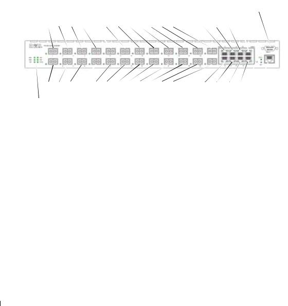
PowerConnect 6024F
The PowerConnect 6024F ports differ from the PowerConnect 6024 only in port designation: Ports 1-16 are designated as SFP ports, and ports 17-24 are designated as combo ports. The port numbers are shown in the figure below.
For information about how the ports function, see the port description for the PowerConnect 6024.
Figure 2-2. PowerConnect 6024F with 24 SFP Ports
|
|
|
|
|
|
|
|
|
|
|
|
|
|
|
Console |
|
|
|
|
|
|
|
|
|
|
|
|
|
|
|
(RS-232) |
|
|
|
|
|
SFP Ports |
|
|
|
|
Base-T Ports |
|||||
1 |
3 |
5 |
7 |
9 |
11 |
13 |
15 |
17 |
19 |
21 |
23 |
17 |
19 |
21 |
23 |
2 |
4 |
6 |
8 |
10 |
12 |
14 |
16 |
18 |
20 |
22 |
24 |
18 |
20 |
22 |
24 |
|
|
|
|
|
SFP Ports |
|
|
|
|
Base-T Ports |
|||||
System LEDs |
|
|
|
|
|
|
|
|
|
|
Reset Button |
||||
Out of Band
Out-of-Band Management Port
The Out-of-Band (OOB) management port is a 10/100 Mbps Ethernet port that you can use to connect directly to the switch to perform system administrator management applications. The Out-of-Band port is regarded as a regular IP interface to the system, and all management interfaces are available over this port.
For more information about configuring Out-of-Band, see "Out-of-Band Management Port."
Console (RS-232) Port
The console (RS-232) port is used only for management via a serial interface. This port is a direct connection to the switch, used to access CLI from a console terminal connected to an EIA/TIA-232 port.
The console port supports synchronous data of eight data bits, one stop bit, and no parity bit. The default baud rate is 115,200 bps.
38 Hardware Description
Hardware Components
Physical Dimensions
The switch has the following physical dimensions:
•440 x 460 x 44 mm (W x D x H).
•17.32 x 18.11 x 1.73 inch (W x D x H).
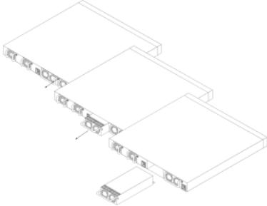
Power Supplies
Your switch is shipped with two internal power supplies. You can verify operation by observing the LEDs. See "System LEDs" for information.
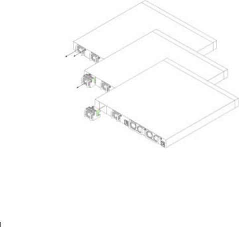
To replace a power supply:
1Remove the faulty power supply unit by removing its screw in the back panel and pulling it out.
2Insert a new power supply into the slot, ensuring that the power supply is inserted fully into the switch.
Figure 2-3. Power Supply Insertion
1
2
3Insert and tighten the screw to the power supply.
4Connect each power supply to a different external power source.
Hardware Description |
39 |
w w w . d e l l . c o m | s u p p o r t . d e l l . c o m
When you connect to a different power source, the probability of the switch failing in the event of a power outage decreases.
Reset Button
The reset button, located on the front panel, manually resets the switch.
Ventilation System
There are two fans in the system. You can verify operation by observing the LEDs. See "System LEDs" for information.
To replace a fan:
1Remove the two screws, and gently pull out the faulty fan.
2Carefully insert the new fan into the slot.
Figure 2-4. Fan Installment/Replacement
1
2
3 Insert and tighten the screw to the fan.
LED Definitions
The front panel contains light emitting diodes (LED) that indicate the status of links, power supplies, fans, and system diagnostics.
40 Hardware Description
Loading...